Embed Size (px)
Citation preview

8/12/2019 Adaptive Vehicle Structure to Optimize Crash Pulses
http://slidepdf.com/reader/full/adaptive-vehicle-structure-to-optimize-crash-pulses 1/10
Witteman, 1
THE NECESSITY OF AN ADAPTIVE VEHICLE STRUCTURE TO OPTIMIZE
DECELERATION PULSES FOR DIFFERENT CRASH VELOCITIES
Dr.ir. W.J. Witteman
Prof.dr.ir. R.F.C. KriensTechnische Universiteit Eindhoven
Automotive Engineering & Product Design Technology
The NetherlandsPaper Number 320
ABSTRACT
To minimize injury to the occupants, the frontal
vehicle structure must absorb much more energy inthe first deformation phase in case of a high-speed
collision. Depending on the crash situation an
intelligent system must regulate the structure stiffness
yielding additional energy absorption by means of
friction. Concept ideas are mentioned to achieve
different crash pulses at different crash velocities
within the available deformation length.
An independent search for optimal deceleration
pulses at several crash velocities is necessary, because
the usually found structure-based pulses are not
obviously the optimal pulses for minimal injury to the
occupants. Therefore, in this paper the more
interesting case of the reverse question is answered:
which crash pulse gives the lowest injury levels with
an already optimized restraint system, instead offinding the optimized restraint system for a given
crash pulse. For this research, a method is described
in which a numeric model of an interior and a FEM
dummy has been used to find the levels of the injurycriteria. To compare the results of different crash
pulses, an overall severity index has been used. From
a described research an optimal pulse has been foundafter several considered pulse variations at a crashspeed of 56 km/h. This pulse, used as example, gives
as it seems much lower injuries. During the first 18
cm deformation length the deceleration level must be
high, then a low deceleration interval is required, and
at the end (dummy is restrained by belt and airbag)
the deceleration must be high again. Also for othercrash velocities, pulses are mentioned with adapted
pulse characteristics for optimal results.
The only way to generate an optimal crash pulse at
different collision speeds is variable structure
stiffness. After detection of the crash velocity, theoptimal stiffness of the front structure should be
realized. Solutions are presented based on
controllable energy absorption by additional friction
or based on controllable hydraulic flow restriction.
With this new design, an optimal vehicle decelerationcurve is possible for each velocity over the entire
frontal collision spectrum, yielding the lowest levels
of the occupant injury criteria, also in case ofcompatibility problems.
INTRODUCTION
The improved frontal crashworthiness of cars
necessitates totally new design concepts, which take
into account that the majority of collisions occur with
partial frontal overlap and under off-axis load
directions. Realistic crash tests with partial overlaphave shown that conventional longitudinal structuresare not capable of absorbing all the energy in the car
front without deforming the passenger compartment.
For improved frontal car safety it is necessary to
design a structure that absorbs enough energy in each
realistic crash situation. To protect the occupants, the
passenger compartment should not be deformed and
intrusion must be avoided too. To prevent excessivedeceleration levels, the available deformation distance
in front of the passenger compartment must be used
completely for a predetermined crash velocity. This
implies that in a given vehicle concept the structuremust have a specific stiffness. Normally, the two
main longitudinal members will absorb most of the
crash energy with a progressive folding deformation
of a steel column. The main problem is that in real carcollisions these two longitudinal members often are
not loaded in a synchronous fashion. The majority of
collisions occur with partial frontal overlap, in which
only one longitudinal is loaded. A design conflict is
that the same amount of energy must be absorbed
either with a single or with both longitudinals. These
problem can not be solved by just increasing thestiffness of the longitudinals in such a way that each
longitudinal is capable of absorbing all of the energy,see the following reasons. To absorb enough energy,
a stiff longitudinal is needed for the offset crash in
which normally only one longitudinal is loaded. The
same longitudinal must be more supple in case of afull overlap crash, since both longitudinals must not
exceed the desired deceleration level (Witteman
1993). Another issue is the crash velocity. To absorb
all the kinetic energy, which is proportional with thesquare of the velocity, the deformable structure length

8/12/2019 Adaptive Vehicle Structure to Optimize Crash Pulses
http://slidepdf.com/reader/full/adaptive-vehicle-structure-to-optimize-crash-pulses 2/10
Witteman, 2
must have a specific stiffness. This stiffness results inan average mean force, which multiplied with the
deformation shortening gives the absorbed energy.
For an acceptable injury level of the occupants, thetotal deceleration level must be as low as possible,
using the maximum available deformation length
without deforming the passenger compartment. This
means that for example in a 64 km/h crash comparedwith a 32 km/h crash, a four times longer deformation
distance is needed for the same deceleration level.
Although the stiffness normally increases during the
crash and at higher crash speeds there is made use ofthe stiff engine; the only way to generate an optimal
crash pulse at different collision speeds is variablestructure stiffness. After detection of the crash
velocity, the optimal stiffness of the longitudinal
member should be realized.
The objective of the research project presented here,
was to design a concept structure that substitutes the
conventional energy absorbing longitudinal membersin a frontal vehicle structure and yields optimized
deceleration pulses for different crash velocities and
overlap percentages. To this aim the structure must
have a stiffness that can be varied in accordance to
the specific crash situations.
The novel design presented in this paper can cope
with the following three crashworthiness problems:
1. In the case of a full overlap crash (both
longitudinals and engine involved) as in the case
of an offset crash (at 40 per cent overlap only one
longitudinal directly involved) a similar amountof energy must be absorbed by the front
structure.
2. With a not much longer deformation length,much more energy must be absorbed at highcrash velocities (resulting in less fatal injuries)
and a lower injury level must be obtained at
lower crash velocities.
3. A deceleration pulse must be obtained which is
optimal (lowest injury level) for the concerning
collision speed and the chosen dummy restraintparameters.
METHOD FOR OPTIMIZING THE
DECELERATION PULSE
The aim of this research is to minimize the injurylevel of the occupant in several frontal collisions.
Therefore, it must be clear which parameters
influence the injury level. If an undeformable
passenger compartment and no intrusion of vehicle
parts like steering wheel, dashboard and pedals areassumed, the injury level is only influenced by means
of g forces of the deceleration pulse generated by the
vehicle front. To be sure that the injury level is the
lowest possible, a numerical model is necessary tocalculate the expected injury level by variation of thedeceleration pulse. If the optimal deceleration pulse
for a specific crash velocity is known, the structure
must be designed to generate such a desired crash
behavior.
With an ideal not deforming passenger compartment,
it is acceptable to use an uncoupled model of the
dummy and the frontal deforming structure. Acommon method is, to predefine a deceleration pulse
as input on the passenger cage. A full frontal coupled
model has a longer calculation time, also because the
dummy movement has a longer crash duration timewhile the frontal structure is already fully deformed.
The usual real time interactions between the occupant
and the vehicle structure during a crash (Khalil 1995),
which influence the vehicle deceleration a little
(Seiffert 1992) by means of the restrained dummymass, can be compensated in the input pulse. Ofcourse for exactly determining the deceleration pulse
of a vehicle structure (not for determining the pulse
that causes the lowest injury level) the dummy masses
must be added to the vehicle model with restraint
characteristics. Of course in case of a side impact an
uncoupled method is not allowed, the dummy mass
and its close position to the door have a not negligible
influence on the deformation behavior of therelatively low mass of the side structure (Landheer
1996).
With the aid of an interior model, variations of thedeceleration pulse can be compared on basis of a
calculated injury level and an optimal pulse can be
obtained for several crash velocities. Structural design
specifications are presented to realize such an optimalpulse and conceptual design ideas will be proposed
which fulfil these desired deceleration levels for
different crash velocities.
To compare the injury severity for different vehicle
collisions, some sort of index or formula is needed.
The regulations for vehicle crashes only prescribe amaximum value not to be exceeded for several
different injury criteria. Because the proposed vehiclemodel has no intrusion, only the injury criteria as
mentioned in Table 1 with their limiting values
(Levine 1994, Mertz 1993, Seiffert 1997) are useful.
An overall severity index can be a specific weighted
combination of these injury criteria, and which takesalso into account the relative importance of individual
changes of these injury criteria (Bakker 1997). The
relative importance to an overall severity index can beexpressed by a weight factor (Viano 1990). For an

8/12/2019 Adaptive Vehicle Structure to Optimize Crash Pulses
http://slidepdf.com/reader/full/adaptive-vehicle-structure-to-optimize-crash-pulses 3/10
Witteman, 3
extended description of an overall severity index see aseparate research of Witteman (1999b).
Table 1.
Relevant injury criteria with their by legislation
limited values
Injury
Criterion
HIC CHEST-
G
CHEST-
D
FEMUR-
F
NECK-
M
Limitvalue
1000 60 g 50 mm 10000 N 189 Nm
Weight
factor
8 2 2 1 2
The Head Injury Criterion (HIC) is calculated on a
specific time interval around a deceleration peak of
the dummy head to reach a maximum value as shown
in next formula, where t1 and t2 are the start and endtime of the considered deceleration interval in
seconds and a(t) is the head deceleration in g as
function of time:
HICt t
a t dt t tt
t
=−
⋅
⋅ −∫ max
( )( ) ( )
.
1
2 1
2 5
2 1
1
2
CHEST-G is the peak deceleration in g of the dummy
chest.
CHEST-D is the peak compression of the dummy
chest, mostly a result of the belt force.
FEMUR-F is the maximal longitudinal force in theupper leg caused by the dashboard.
NECK-M is the flexion bending moment of the
dummy neck by forward head rotation.
To simulate the movement behavior of an occupant
and to measure the forces working on the body, usecan be made of a modern deformable frontal finite
element dummy Hybrid III (ESI 1996). This dummy
consists of rigid body elements and a full deformablethorax and pelvis and is developed by the safety
group of ESI SA (Rungis, France) in collaboration
with the Biomechanics Department of Wayne StateUniversity (Detroit, USA). This numerical dummysimulates the crash dummy of a full-scale frontal
crash. In literature a good correlation is reported
between computed accelerations of the basic rigid
body dummy and measured accelerations in a sledtest (Ni 1991). Also the new dummy with deformable
chest and pelvis, shows good correlation’s with lowand high speed pendulum impact tests and with a sled
test (ESI 1996, Schlosser 1995).
The dummy model must be positioned inside a
realistic vehicle interior model (Bosch 1993, Relou1995, Seiffert 1989, Wijntuin 1995). To this aim, a
seat, a dashboard with steering wheel, a floor planeand a restraint system must be modeled, see Figure 1.
The restraint system consists of a belt with automatic
lock and a retractor, and a folded (as far as necessary)
airbag (Hoffman 1989). The folding FEM airbag has
a good interaction with a dummy and shows a goodagreement with experimental data (Hoffmann 1990,
Lasry 1991). The seat has a so-called anti
submarining plate, which prevents forward moving ofthe dummy pelvis under the lap belt.
Figure 1. Dummy positioning within the interior
with restraint systems.
A speed of 56 km/h against a rigid barrier is a realistic
test speed because it gives a balance between
acceptable injuries at lower speeds and minor
fatalities at higher speeds.
RESULTS
Research has been carried out (Witteman 1999b) to
find a deceleration pulse (the resulting deceleration-
time signature on the vehicle passenger compartment
generated when a collision occurs) with a minimal
injury risk, based on the lowest value of the overall
severity index, at a 56 km/h crash during 90 ms. This
pulse determines the occupant loading and hence the
injury risk for a passenger in a vehicle involved in anaccident. In this research the reverse approach is usedby answering the question which crash pulse gives the
lowest injury levels with an already optimized
restraint system, instead of finding the optimized
restraint system for a given crash pulse. In Figure 2
the optimal pulse for 56 km/h is given with thecorresponding velocity and deformation length curve
against time, in which three deceleration levels can be

8/12/2019 Adaptive Vehicle Structure to Optimize Crash Pulses
http://slidepdf.com/reader/full/adaptive-vehicle-structure-to-optimize-crash-pulses 4/10
Witteman, 4
distinguished. These three phases can correspondsuccessively with the crash initiation phase (sensor
triggering), the airbag deployment phase and finally
the occupant contact phase (Brantman 1991).
Figure 2. Optimal deceleration pulse and the
velocity and deformation curve.
In Figure 3 the specific injury time plots of this new
optimal pulse are given as an example. The injuryvalues are plotted with a SAE180_5 filter with the
times until 150 ms on the x-axis and on the y-axis for
the HIC the deceleration in mm/ms2, for the CHEST-
G also the deceleration in mm/ms2, for the CHEST-D
the negative elongation (deflection) in mm of 7 bar
elements perpendicular to the chest (where the
CHEST-D is calculated as the average of this 7distances), for the FEMUR-F the force in kN, and forthe NECK-M the flexion moment in kNmm. Note the
balanced course of the curves yielding the lowest
injury values. For this optimal pulse the calculated
injury values are given as indication in Table 2. The
values are far below the limit values of Table 1.
Table 2.
Simulation results for the injury types of an
optimized pulse at 56 km/h
Injury
Criterion
HIC CHEST-
G
CHEST-
D
FEMUR-
F
NECK-
MSimulati-on value
251 31 g 21 mm 5066 N 29 Nm
0 5 0 1 0 0 1 5 00
0 . 1
0 . 2
0 . 3
0 . 4
0 . 5
0 . 6
0 . 7
m m / m s 2
T i m e [ m s ]
M a g n i t u d e ( S a e 1 8 0 _ 5 ( A c c e le r a t i o n [ 8 5 0 1 0 1 ] ) H IC ) )H I C = 2 5 1 . 2
P u ls e - V 5 6 - 1 5
HIC
0 5 0 1 0 0 1 5 00
0 . 1
0 . 2
0 . 3
0 . 4
0 . 5
m m / m s 2
T i m e [ m s ]
M a g n i t u d e ( S a e 1 8 0 _ 5 ( A c c e le r a t i o n [ 8 5 0 3 0 1 ] ) M S ) )
C H E S T G = 3 1 . 0 2
P u ls e - V 5 6 - 1 5
CHEST-G
0 5 0 1 0 0 1 5 0- 6 0
- 5 0
- 4 0
- 3 0
- 2 0
- 1 0
0
m m
T i m e [ m s ]
B a r A x i a l E l o n g a t i o n [ 5 3 0 0 0 0 t / m 5 3 0 0 0 6 ]
C H E S T D = 2 0 . 8 5
P u ls e - V 5 6 - 1 5
CHEST-D
0 5 0 1 0 0 1 5 00
1
2
3
4
5
6
7
k N
T i m e [ m s ]
S a e 1 8 0 _ 5 ( S P R I N G L o c a l F o r c e - M a g n i t u d e [ 9 1 4 1 0 0 ] = - .
S a e 1 8 0 _ 5 ( S P R I N G L o c a l F o r c e - M a g n i t u d e [ 9 1 8 1 0 0 ] = -
F E M U R F = 5 0 6 6
P u ls e - V 5 6 - 1 5
FEMUR-F
0 5 0 1 0 0 1 5 0- 1 0
0
1 0
2 0
3 0
4 0
5 0
6 0
7 0
8 0
9 0
k N m m
T i m e [ m s ]
S a e 1 8 0 _ 5 ( S p h e r e J o i n t M o m e n t a b o u t [ 9 0 2 1 0 0 ]
N E C K M = 2 8 . 9 2
P u ls e - V 5 6 - 1 5
NECK-M
Figure 3. Injury values of an optimal pulse for 56
km/h.
Structural Design Specifications for Different
Crash Velocities
Since more than 90 per cent of all frontal collisions
occurs at a velocity lower than the prescribed crashvelocity of 56 km/h (Witteman 1999a), also an
optimal pulse for lower collision velocities is
necessary to minimize the occupant injury level at
that lower velocity. Although only 2 to 10 per cent
(dependent of the overlap percentage) of all crashestakes place at a velocity higher than 56 km/h, also a
pulse optimized at such a velocity is interesting
because of the higher energy level yielding larger
vehicle deformations and higher injury levels. If the
0 5 10 15 20 25 30 35 40 45 50 55 60 65 70 75 80 85 90
time [ms]
05
1015202530354045505560657075
deceleration[g],deformation[cm],velocity[km / h]
Decelerati on Deformati on Veloc ity
time [ms]
d e c e l e r a t i o n [ g ] , d e f o r m a t i o n [ c m ] , v e l o c i t y [ k m / h
]

8/12/2019 Adaptive Vehicle Structure to Optimize Crash Pulses
http://slidepdf.com/reader/full/adaptive-vehicle-structure-to-optimize-crash-pulses 5/10
Witteman, 5
initial crash velocity is decreased to 32 km/h, thisresults in a decrease of crash energy of 67 per cent
with respect to a crash speed of 56 km/h, so the
vehicle might just be too stiff. An increase of theinitial crash velocity to 64 km/h results in an increase
of energy of 31 per cent, so the structure might be too
supple. An optimal pulse for a speed of 64 km/h (total
deformation length of 762 mm) is plotted in Figure 4together with the already mentioned optimal pulse for
56 km/h (total deformation length of 724 mm) and
with an optimal pulse for a collision with 32 km/h
(total deformation length of 448 mm). Theseadditional pulses are obtained with the same
numerical research.
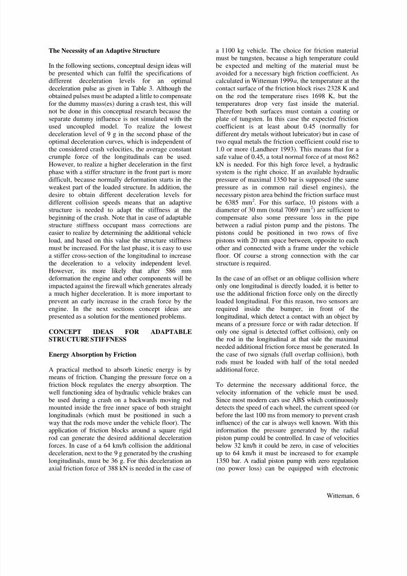
Before designing structural solutions to realize the
desired deceleration pulses (see next sections), first
the specifications for this design will be mentioned.
For these specifications the optimal curves that were
obtained for three different crash velocities as shown
in Figure 4 will be used. In this figure the velocitydecrease is plotted against deformation length instead
of time, because it is more interesting to know on
which length position in the car structural measures
are necessary to realize a change in stiffness
corresponding with the desired change in deceleration
level. In Table 3 the time duration and deformation
length of each deceleration interval are presented. As
can be seen the difference in deformation length in
the first interval of the 56 km/h and the 64 km/hcollision is small. So for simplification the lengths of
170 mm and 188 mm could be joined together on 179
mm. At the end of the second interval the deformation
length is already identical for both velocities, vz. 586mm. These interval borders are visualized in Figure 4
as two vertical lines. For the 32 km/h collision there
is no difference in deceleration between the first twointervals.
0 4 8 1 2 1 6 2 0 2 4 2 8 3 2 3 6 4 0 4 4 4 8 5 2 5 6 6 0 6 4 6 8 7 2 7 6 8 0
deformation length [cm]
0
4
8
1 2
1 6
2 0
2 42 8
3 2
3 6
4 0
4 4
4 8
5 2
5 6
6 0
6 4
velocity[km / h]
56 km/h 64 km/h 32 km/h
45g
32g
9g
9g
9g
9g
23g
23g
Figure 4. Three optimal decelerations curves in
three phases (Witteman 1999 b).
The optimal pulse obtained for higher velocities has ahigher deceleration level in the first interval and the
levels of the middle and the third interval remain
unchanged in comparison with an optimized pulse for56 km/h.
The obtained optimal pulse for a collision with 32
km/h has a constant deceleration level of 9 g, thesame level as the higher velocity pulses have during
their middle interval.
From these observations it can be concluded with theconsidered numerical model, that for minimal injury
for crash velocities starting at 32 km/h the vehiclestructure needs a constant stiffness to decelerate 9 g
during the first 586 mm. For higher velocities as 32
km/h the stiffness of the first 179 mm must be
directly increased to decelerate up to 45 g for the
highest velocity of 64 km/h. After 586 mm
deformation has been reached the stiffness must be
increased to decelerate to 23 g for all relevantvelocities.
Table 3.
Deceleration parameters of 3 crash velocities
(Witteman 1999 b)
Crash
velocity
32 km/h 56 km/h 64 km/h
Phase 1
Deceleration 9 g 32 g 45 g
Deformation
length
170 mm 188 mm
Time
duration
12.5 ms 12.5 ms
Phase 2
Deceleration 9 g 9 g 9 g
Deformation
length
total 448
mm
416 mm,
total 586 mm
398 mm,
total 586 mm
Time
duration
100.7 ms 42.5 ms,
total 55 ms
37.5 ms,
total 50 ms
Phase 3
Deceleration 23 g 23 g
Deformation
length
138 mm,
total 724 mm
176 mm,
total 762 mm
Time
duration
35 ms,
total 90 ms
39.4 ms,
total 89.4 ms
v e l o c i t y [ k m / h ]
deformation length [cm]
56 km/h 64 km/h 32 km/h
8/12/2019 Adaptive Vehicle Structure to Optimize Crash Pulses
http://slidepdf.com/reader/full/adaptive-vehicle-structure-to-optimize-crash-pulses 6/10
Witteman, 6
The Necessity of an Adaptive Structure
In the following sections, conceptual design ideas will
be presented which can fulfil the specifications ofdifferent deceleration levels for an optimal
deceleration pulse as given in Table 3. Although the
obtained pulses must be adapted a little to compensate
for the dummy mass(es) during a crash test, this willnot be done in this conceptual research because the
separate dummy influence is not simulated with the
used uncoupled model. To realize the lowest
deceleration level of 9 g in the second phase of theoptimal deceleration curves, which is independent of
the considered crash velocities, the average constantcrumple force of the longitudinals can be used.
However, to realize a higher deceleration in the first
phase with a stiffer structure in the front part is more
difficult, because normally deformation starts in the
weakest part of the loaded structure. In addition, the
desire to obtain different deceleration levels for
different collision speeds means that an adaptivestructure is needed to adapt the stiffness at the
beginning of the crash. Note that in case of adaptable
structure stiffness occupant mass corrections are
easier to realize by determining the additional vehicle
load, and based on this value the structure stiffness
must be increased. For the last phase, it is easy to use
a stiffer cross-section of the longitudinal to increase
the deceleration to a velocity independent level.
However, its more likely that after 586 mmdeformation the engine and other components will be
impacted against the firewall which generates already
a much higher deceleration. It is more important to
prevent an early increase in the crash force by theengine. In the next sections concept ideas are
presented as a solution for the mentioned problems.
CONCEPT IDEAS FOR ADAPTABLESTRUCTURE STIFFNESS
Energy Absorption by Friction
A practical method to absorb kinetic energy is bymeans of friction. Changing the pressure force on a
friction block regulates the energy absorption. The
well functioning idea of hydraulic vehicle brakes can
be used during a crash on a backwards moving rodmounted inside the free inner space of both straight
longitudinals (which must be positioned in such a
way that the rods move under the vehicle floor). Theapplication of friction blocks around a square rigid
rod can generate the desired additional deceleration
forces. In case of a 64 km/h collision the additional
deceleration, next to the 9 g generated by the crushing
longitudinals, must be 36 g. For this deceleration anaxial friction force of 388 kN is needed in the case of
a 1100 kg vehicle. The choice for friction material
must be tungsten, because a high temperature could
be expected and melting of the material must beavoided for a necessary high friction coefficient. Ascalculated in Witteman 1999a, the temperature at the
contact surface of the friction block rises 2328 K and
on the rod the temperature rises 1698 K, but the
temperatures drop very fast inside the material.
Therefore both surfaces must contain a coating orplate of tungsten. In this case the expected friction
coefficient is at least about 0.45 (normally for
different dry metals without lubricator) but in case oftwo equal metals the friction coefficient could rise to
1.0 or more (Landheer 1993). This means that for a
safe value of 0.45, a total normal force of at most 862
kN is needed. For this high force level, a hydraulicsystem is the right choice. If an available hydraulic
pressure of maximal 1350 bar is supposed (the same
pressure as in common rail diesel engines), the
necessary piston area behind the friction surface must
be 6385 mm2. For this surface, 10 pistons with adiameter of 30 mm (total 7069 mm
2) are sufficient to
compensate also some pressure loss in the pipe
between a radial piston pump and the pistons. The
pistons could be positioned in two rows of five
pistons with 20 mm space between, opposite to each
other and connected with a frame under the vehicle
floor. Of course a strong connection with the car
structure is required.
In the case of an offset or an oblique collision where
only one longitudinal is directly loaded, it is better to
use the additional friction force only on the directly
loaded longitudinal. For this reason, two sensors arerequired inside the bumper, in front of the
longitudinal, which detect a contact with an object by
means of a pressure force or with radar detection. Ifonly one signal is detected (offset collision), only onthe rod in the longitudinal at that side the maximal
needed additional friction force must be generated. In
the case of two signals (full overlap collision), both
rods must be loaded with half of the total needed
additional force.
To determine the necessary additional force, the
velocity information of the vehicle must be used.
Since most modern cars use ABS which continuouslydetects the speed of each wheel, the current speed (or
before the last 100 ms from memory to prevent crash
influence) of the car is always well known. With thisinformation the pressure generated by the radial
piston pump could be controlled. In case of velocities
below 32 km/h it could be zero, in case of velocities
up to 64 km/h it must be increased to for example
1350 bar. A radial piston pump with zero regulation(no power loss) can be equipped with electronic

8/12/2019 Adaptive Vehicle Structure to Optimize Crash Pulses
http://slidepdf.com/reader/full/adaptive-vehicle-structure-to-optimize-crash-pulses 7/10
Witteman, 7
pressure control. Another possibility is to keep thehighest pressure always available and control the
magnetic valves on each piston (comparable with
common rail diesel engines). Probably this is forfaster adjustments in the very short time preferable. In
Table 4, the required number of opened valves is
mentioned. In case of a symmetric collision the
number is valid for each longitudinal, in case of anasymmetric collision the number is only valid for the
directly loaded longitudinal, the valves of the other
longitudinal must be closed. Of course for other
collision speeds between 32 km/h and 64 km/h anumber between the mentioned numbers could be
chosen.
Table 4.
Example of number of opened valves to reach
enough pressure for additional friction force
Crash velocity 32 km/h 56 km/h 64 km/h
Symmetric collision 0 valves 3 valves 5 valves
Asymmetric collision 0 valves 6 valves 10 valves
After 179 mm deformation, the additional frictionforce must be removed. This can be done by moving
rapidly the zero regulation rod, which controls the
eccentricity of the radial piston pump axle, so the oil
flows in the opposite direction back and lifts the
pistons from the rod. The movement of the zero
regulation rod can be done electronically by the
pressure control module or it can be donemechanically by a mechanism connected with the
zero regulation rod and activated at the right moment
by the crossing rod. Another possibility is the use of a
large electronic valve in the common pressure pipe,
which releases the pressure rapidly.
The third phase of the deceleration curve starts
always at 586 mm deformation length. From this
point, the deceleration must be increased from 9 to 23g as long as the crash lasts. If the engine is involved
before this point, which is plausible in smaller cars, a
solution could be flexible engine mounting points. In
addition, the connection of the engine with the drive
line must be movable to prevent high translationforces on the engine too early. All the aggregates
must be positioned in such a way that only after 586mm deformation has been reached, high contactforces start to press the aggregates together. In
addition, the front wheels have to deform the wheel
bay and the sill. Finally, the engine hits the stiff
firewall, which could deform at high collision speeds.
The final deformation forces are very dependent on
the positioning and the dimensions of the aggregates
and the free space under the bonnet. If the necessaryforce level is not reached, assistance of the friction
force as used in the first phase of the collision isalways possible. Signals must be send to the pressure
regulation module and the valves to control the
correct friction force.
Future Possibilities
An optimal regulation for the whole deformation
length is of course with a computer controlled system,which measures continuously the actual deceleration
level and adjusts at the same time the pressure to
reach the programmed optimal deceleration pulse.Maybe when very fast sensors, high-pressure valves
and control modules are available this is a realizable
idea. In this way, it is also possible to compensate for
the stiffness, velocity or weight of the colliding
obstacle. This would be an ideal solution for the
compatibility problem between small and largevehicles. If this system is fast enough and veryreliable, it is possible to think about a structure which
has only two very stiff beams, which can fully slide
backwards without deformation. A heavy computer
controlled break system regulates the desired
deceleration. Sensors already send signals to increase
the friction of one loaded beam to reach the same
energy absorption in case of an offset collision. The
new beams have not to crumple to absorb energy sothey can be made very stiff with a high bending
resistance yielding no risk for a premature bending
collapse in case of an oblique crash direction. Of
course the control system with the breaks must bereliable in all crash situations because there is no
alternative to moderate the energy absorption, which
means that large force level differences must be taken
care of. Only problem could be the space behind thefirewall or under the vehicle floor. Vehicles with
structural space under the passenger compartment
have very good possibilities for safety increasing
features, also for side impact crashworthiness. A very
nice vehicle concept for this application is the
Mercedes-Benz A-class vehicle. Because of thedouble floor with a higher placed passenger
compartment, the longitudinals stay fully horizontally
in a stiff ladder chassis. In the floor structure there isenough space for rearward sliding beams and for the
positioning of the energy absorbing brake system.
Furthermore, the engine does not shorten the
available deformation length or penetrate the firewallsince it moves to the road surface. Maybe with the
popularity of space wagons or mini multi purpose
vehicles nowadays, this is an interesting design
aspect. Occupants are not longer sitting in theextension of the crumple zone but above, especially at

8/12/2019 Adaptive Vehicle Structure to Optimize Crash Pulses
http://slidepdf.com/reader/full/adaptive-vehicle-structure-to-optimize-crash-pulses 8/10
Witteman, 8
side impact crashes. In the case of structural spacebehind the firewall, the hydraulic piston solution
presented in next section is another possibility.
Design of a Hydraulically Controlled Frontal Car
Structure
To load the missed longitudinal member during anasymmetric collision, it is possible to use a hydraulic
system. In Figure 5, a principle sketch of the system
is shown with besides the longitudinals two cylinders
with pistons.
Figure 5. A hydraulically controlled frontal carstructure.
The cylinder rods are fixed to the cross member, just
like the front ends of the longitudinals. If one of the
longitudinals is loaded during an offset crash, it starts
to deform and because of the connection to the
cylinder, the rod slides into the cylinder. The oil
inside the cylinder is pressed via a tube or pipe to therod side of the cylinder of the unloaded longitudinal.
Under the influence of this oil pressure, the piston of
this cylinder is also pushed backwards. Because this
piston is connected to the unloaded longitudinal
member, it is forced to collapse in an axial folding
mode. The pressure that arises in the cylinder of theunloaded longitudinal is led back to the rod side of
the cylinder of the loaded longitudinal, where it helps
to further move the piston inside the cylinder. Hence,the hydraulic cylinders form a closed-loop system.
Note that in the case of a full overlap collision where
both longitudinals are loaded, the system is in
equilibrium and does not influence the crashbehavior.
One problem is however, that the oil volume in thecylinder does not fit in the other cylinder at the rodside, because of the volume of the rod itself. Because
the rods move inwards, the total available volumedecreases. Solution is a piston with at each side a rod,
where the second rod has not a force function but
causes identical volumes exchanges. For this solution
there must be space behind the firewall where the
additional rods can move backwards. Advantage is
the same area at each piston side, which gives a 1:1
force transmission.
A second problem is the available deformation length,because a cylinder with piston can be shortened less
as half of the original length. For this reason it is also
necessary that there is much horizontal space under
the passenger floor, because then the cylinders could
be mounted at the rear of the firewall. For theconnection pipes, enough space is also important
because they must have a large diameter and a short
length to minimize the pressure loss at high streamvelocities. With a cylinder diameter of 90 mm, the
pressure at a crash load of 150 kN is 236 bar. At an
initial flow rate of 15 m/s (56 km/h crash), thepressure loss in the connection pipe with a diameter
of 30 mm and with oil ISO VG2 is 12 bar/m and 1
bar/m for a pipe diameter of 60 mm (Slaats 1996b).
Although the guaranteed maximal velocity for the
cylinder’s sealing is much lower, the high velocity
works a very short time and the system has to workonly one movement.
The final structure can be built together, the rod of the
cylinder can be positioned inside the crushing
longitudinals, and gives additional bending resistance.
The stiff cylinder behind the longitudinal can be used
as support structure for the axial crushing forces.
This hydraulic supported structure generates aconstant deceleration force, independent of the
overlap percentage. However, to reach the optimal
crash pulse, control of the oil flow is necessary. In
this case, a valve with a controllable flow restriction(Janssen 1994) or several valves must be used in the
outlet of the backside of the cylinders. Reducing the
outlet area increases the pressure and therefore the
stiffness of the system. After the first decelerationinterval, the valve can be fully opened and for the
third interval, if necessary the total outlet area can be
reduced again.
CONCLUSIONS
A method has been described how a deceleration
pulse can be optimized. As an example three pulses
are mentioned for three different velocities to use asspecification for conceptual design ideas. To fulfil the
requirements for different velocities an intelligent
structure is desirable. With the use of an additional
friction force on rearwards moving rods mountedinside the free inner space of the longitudinals, it must
be possible with a hydraulic system to control the
deceleration pulse to the optimal level dependent on
the crash velocity. In case of a multi purpose vehicleconcept (component space under the passenger floor)
Before the crash After the crash

8/12/2019 Adaptive Vehicle Structure to Optimize Crash Pulses
http://slidepdf.com/reader/full/adaptive-vehicle-structure-to-optimize-crash-pulses 9/10
Witteman, 9
a new hydraulic brake or flow system for controlledenergy absorption is a promising idea. This intelligent
structure with adaptable stiffness is also a solution for
the compatibility problem between different vehiclesor for compensating the additional occupant and
luggage masses.
REFERENCES
Bakker, S.O., Optimising Deceleration Pulses -
Lowering injury levels for different collision velocities,
Master’s thesis, Internal report WOC/VT/R/97.04,Eindhoven University of Technology, Automotive
Engineering & Product Design Technology, Eindhoven,The Netherlands, 1997.
Bosch, Automotive Handbook 3rd edition, pp. 649,
1993.
Brantman, R., Achievable Optimum Crash Pulses for
Compartment Sensing and Airbag Performance,
Thirteenth International Technical Conference on
Experimental Safety Vehicles (ESV), Paper S9-O-22,
pp. 1134-1138, Paris, France, 1991.
ESI Group Software Product company, OccupantDatabase, PAM-SAFE™ Version 1996, PAM SystemInternational, 1996.
Hoffman, R., Pickett, A.K., Ulrich, D., Haug, E.,
Lasry, D., Clinkemaillie, J., A Finite Element
Approach to Occupant Simulation: The PAM-
CRASH Airbag Model, SAE paper no. 890754, 1989.
Hoffmann, R., Ulrich, D., Protard, J.-B., Wester, H.,Jaehn, N., Scharnhorst, T., Finite Element Analysis of
Occupant Restraint System Interaction with PAM-
CRASH, 34th Stapp Car Crash Conference, Orlando,
Florida, 1990.
Janssen, R.A.M., Alternatieven voor energiedissipatie
bij frontale botsingen (Alternatives for Energy
absorption in Frontal Collisions), in Dutch, Master’s
thesis, Internal report WOC/VT/R/94.48, EindhovenUniversity of Technology, Automotive Engineering &
Product Design Technology, Eindhoven, The
Netherlands, 1994.
Khalil, T.B., Sheh, M.Y., Chalons, P., Dubois, P.A.,
Integrated Vehicle-Dummy-Airbag Model for Frontal
Crash Simulation by FE Analysis, AMD-Vol.
210/BED-Vol. 30, Crashworthiness and OccupantProtection in Transportation Systems, ASME, pp. 355-
382, 1995.
Landheer, D., Gee, A.W.J. de, Dynamische
Contactverschijnselen (Dynamic Contact Phenomena),
in Dutch, Lecture notes college 4B500, EindhovenUniversity of Technology, Eindhoven, TheNetherlands, 1993.
Landheer jr., D., Witteman, W.J., Kriens, R.F.C.,
Crashworthiness in the Concept Stage: A Parametric
Body Design Method, Proceedings of the 26th FISITACongress, Paper B16.54, 16p, Prague, Czech Republic,
1996.
Lasry, D., Hoffmann, R., Protard, J.-B., Numerical
Simulation of Fully Folded Airbags and Their
Interaction with Occupants with Pam-Safe, SAE Paper
no. 910150, 1991.
Levine, R.S., Head and Neck Injury, Chapter 5, USA,
SAE P-276, ISBN 1560914998, 1994.
Mertz, H., Patrick, L., Strength and response of thehuman neck, pp. 821-846, From: Biomechanics ofimpact injury and injury tolerances of the head-neck
complex, USA, SAE PT-43, ISBN 1560913630,
1993.
Ni, X., Lasry, D., Haug, E., Hoffmann, R., Advances in
Problem-Adaptive Occupant Modelling with PAM-
SAFE, Proceedings of the Thirteenth International
Technical Conference on Experimental Safety Vehicles(ESV), Paper 91-S9-O-20, Paris, France, 1991.
Relou, J.J.M.G., Integrated Crash Simulation of a
Frontal Crash Structure and a Dummy, Master’s thesis,Internal report WOC/VT/R/95.66, Eindhoven
University of Technology, Automotive Engineering &
Product Design Technology, Eindhoven, The
Netherlands, 1995.
Schlosser, J., Ullrich, P., Industrial Applications of
PAM-SAFE in Occupant Simulation at Audi,
PAM’95 Fifth European Workshop on Advanced
Finite Element Simulation Techniques, Bad Soden,
Germany, 1995.
Seiffert, U., Scharnhorst T., Die Bedeutung von
Berechnungen und Simulationen f ür denAutomobilbau - Teil 1, Automobiltechnische
Zeitschrift 91, pp. 241-246, 1989.
Seiffert, U., Fahrzeugsicherheit, VDI-Verlag, ISBN3-18-401264-6, Düsseldorf, 1992.
Seiffert, U., Möglichkeiten und Grenzen der neuen
Frontal- und Seitenaufprall-Gesetzgebung, ATZ 9, pp.494-504, 1997.

8/12/2019 Adaptive Vehicle Structure to Optimize Crash Pulses
http://slidepdf.com/reader/full/adaptive-vehicle-structure-to-optimize-crash-pulses 10/10
Witteman, 10
Slaats, P.M., Design of a Frontal Car Structure forOffset Collisions, Interim Assignment, Internal report
WOC/VT/R/96.61, Eindhoven University of
Technology, Automotive Engineering & ProductDesign Technology, Eindhoven, The Netherlands,
1996b.
Viano, D.C., Arepally , S., Assessing the SafetyPerformance of Occupant Restraint Systems, SAE
paper no. 902328, 1990.
Wijntuin, A.L.M., Evaluation of vehicle interiordimensions and numerical modeling of interior foam
padding, Practical assignment, Internal reportWOC/VT/R/95.56, Eindhoven University of
Technology, Automotive Engineering & Product
Design Technology, Eindhoven, The Netherlands,
1995.
Witteman, W.J., Insufficiency of a Single Frontal
Impact test for Vehicle Crashworthiness Assessment,Proceedings of the 26
th ISATA Conference, Paper
93SF069, pp. 307-314, Aachen, Germany, 1993.
Witteman, W.J., Improved Vehicle Crashworthiness
Design by Control of the Energy Absorption for
Different Collision Situations, Ph.D. thesis, Eindhoven
University of Technology, Automotive Engineering &
Product Design Technology, Eindhoven, The
Netherlands, ISBN 90-386-0880-2, 1999a.
Witteman, W.J., Kriens, R.F.C., Numerical
Optimization of Crash Pulses, Proceedings PAM’99,
Ninth European Seminar on Advanced Finite ElementSimulation Techniques, 52p., Darmstadt, Germany,
1999b.