Embed Size (px)
Citation preview

ADAPTIVE SIMPLIFIED FUZZY LOGIC CONTROLLER FOR DEPTH CONTROL
OF UNDERWATER REMOTELY OPERATED VEHICLE
MOHD SHAHRIEEL BIN MOHD ARAS
A thesis submitted in fulfilment of the
requirements for the award of the degree of
Doctor of Philosophy (Electrical Engineering)
Faculty of Electrical Engineering
Universiti Teknologi Malaysia
APRIL 2015
iii
DEDICATION
This project is dedicated to my mom, Mariam binti Mahat, my lovely wife Norzaima
binti Zainal Badri and my sons Ammar Zulqarnain, Adam Zahirulhaq and Annas
Zulqairy and not forgets to my friends who have always sincerely pray for my success
and glory.
iv
ACKNOWLEDGEMENTS
Alhamdullillah, I am being grateful to ALLAH SWT on His blessing in
completing this research. I would like to express my deepest gratitude and thanks to Dr.
Shahrum Shah bin Abdullah, my honorable supervisor, for his continuous guidance,
committed support, critics, and invaluable advice throughout my study.
I wish to express my gratitude to Ministry of Higher Education and the
honorable University (Universiti Teknikal Malaysia Melaka) especially higher
management for giving a support and budget. And also would like to thank UTM
(Universiti Teknologi Malaysia) especially Faculty of Electrical Engineering because
their tolerance for complete this research successfully.
I would also wish to extend my gratitude to my mother, my wife and family for
their support and their understanding. And of course to all my friends that help me in
this research.
Thank you very much…
v
ABSTRACT
A Remotely Operated Vehicle (ROV) is one class of the unmanned underwater vehicles
that is tethered, unoccupied, highly manoeuvrable, and operated by a person on a
platform on water surface. For depth control of ROV, an occurrence of overshoot in the
system response is highly dangerous. Clearly an overshoot in the ROV vertical
trajectory may cause damages to both the ROV and the inspected structure.
Maintaining the position of a small scale ROV within its working area is difficult even
for experienced ROV pilots, especially in the presence of underwater currents and
waves. This project, focuses on controlling the ROV vertical trajectory as the ROV tries
to remain stationary on the desired depth and having its overshoot, rise time and settling
time minimized. This project begins with a mathematical and empirical modelling to
capture the dynamics of a newly fabricated ROV, followed by an intelligent controller
design for depth control of ROV based on the Single Input Fuzzy Logic Controller
(SIFLC). Factors affecting the SIFLC were investigated including changing the number
of rules, using a linear equation instead of a lookup table and adding a reference model.
The parameters of the SIFLC were tuned by an improved Particle Swarm Optimization
(PSO) algorithm. A novel adaptive technique called the Adaptive Single Input Fuzzy
Logic Controller (ASIFLC) was introduced that has the ability to adapt its parameters
depending on the depth set point used. The algorithm was verified in MATLAB®
Simulink platform. Then, verified algorithms were tested on an actual prototype ROV
in a water tank. Results show it was found that the technique can effectively control the
depth of ROV with no overshoot and having its settling time minimized. Since the
algorithm can be represented using simple mathematical equations, it can easily be
realized using low cost microcontrollers.
vi
ABSTRAK
Kenderaan Operasi Kawalan Jauh (ROV), adalah salah satu daripada kenderaan dalam
air tanpa manusia, mempunyai kabel dan mudah dikendalikan oleh jurumudi daripada
platform di permukaan air. Bagi kawalan kedalaman ROV, sekiranya ia terlajak
daripada had ketetapan kedalaman yang dikehendaki, maka risikonya adalah sangat
berbahaya. Jelas sekali, sekiranya ia melebihi had kedalaman yang ditetapkan,
kerosakan pada ROV atau pada struktur yang hendak diperiksa boleh berlaku.
Penstabilan posisi ROV skala kecil di kawasan kerjanya adalah satu tugas yang sukar,
terutamanya apabila ada arus dalam air dan ombak, walaupun dikendalikan oleh
jurumudi ROV yang berpengalaman. Projek ini memberi fokus kepada reka bentuk
pengawal ROV bagi memastikan ianya stabil dan mengikut kedalaman yang telah
ditetapkan tanpa wujudnya lajakan, dengan memiliki masa naik dan masa pengenapan
yang pantas. Projek ini bermula dengan permodelan matematik dan empirikal bagi
mewakilkan keadaan dinamik sebuah ROV baru dengan diikuti oleh reka bentuk
pengawal pintar bagi kawalan kedalaman ROV. Pengawal pintar yang digunakan adalah
berdasarkan Pengawal Logik Kabur Satu Masukkan (SIFLC) dimana faktor-faktor yang
mempengaruhinya seperti jumlah aturan, penggunaan persamaan linear dan
penambahan model rujukan telah dikaji. Parameter yang optima bagi SIFLC telah
ditentukan menggunakan algoritma Pengoptimuman Kumpulan Zarah (PSO). Satu
kaedah pengawal mudah suai baru telah diperkenalkan iaitu Mudah Suai Pengawal
Logik Kabur Satu Masukkan (ASIFLC) yang mempunyai kebolehan menyesuaikan
parameternya bergantung kepada nilai kedalaman yang ditetapkan. Pelaksanaan
pengawal baru ini telah disahkan menggunakan perisian MATLAB® Simulink.
Algoritma ini kemudiannya diuji pada prototaip sebenar ROV di dalam tangki air.
Keputusan membuktikan bahawa teknik ini berjaya mengawal ROV dengan berkesan
dengan tiada lajakan dan dengan masa pengenapan yang singkat. Oleh kerana algoritma
pengawal ini dapat diwakilkan menggunakan persamaan matematik yang mudah, ianya
boleh direalisasikan dengan menggunakan pengawal mikro kos rendah.
vii
TABLE OF CONTENTS
CHAPTER TITLE PAGE
DECLARATION ii
DEDICATION iii
ACKOWLEDGEMENT iv
ABSTRACT v
ABSTRAK vi
TABLE OF CONTENTS vii
LIST OF TABLES xii
LIST OF FIGURES xiii
LIST OF SYMBOLS xx
LIST OF ABBREVIATIONS xxii
LIST OF APPENDICES xxv
1 INTRODUCTION 1
1.1 Introduction 1
1.2 Research Background 4
1.3 Problem Statement and Significant of the Research 7
1.4 Objectives of the Research 9
1.5 Research Scopes 9
1.6 Contribution of the Research Work 11
1.7 Organization of the Thesis 12
1.8 Summary 14
viii
2 LITERATURE REVIEW 15
2.1 Introduction 15
2.2 Control System of the ROV 16
2.3 Depth Control of the ROV 19
2.4 Critical Review of the ROV Depth Control from
Existing Works 22
2.5 System Identification 23
2.6 Fuzzy Logic Controller 24
2.7 Single Input Fuzzy Logic Controller 25
2.8 Particle Swarm Optimization (PSO) 26
2.9 Hardware comparison 28
2.9.1 UTeRG ROV 28
2.10 Summary 29
3 RESEARCH METHODOLOGY 30
3.1 Introduction 30
3.2 ROV Coordinate System 32
3.3 Modelling of the ROV 34
3.4 Assertions on Dynamics Equation of the ROV 36
3.4.1 Low Speed 36
3.4.2 Roll and Pitch 36
3.4.3 Symmetry 37
3.4.4 Environmental Disturbances 38
3.4.5 Decoupling 39
3.5 Simplified Equations of the ROV Modelling 39
3.5.1 Mass and Inertia Matrix 40
3.5.2 Hydrodynamic Damping Matrix 41
3.5.3 Gravitational and Buoyancy Vector 41
3.5.4 Forces and Torque Vector 43
3.6 Factors Affecting the ROV Design 45
3.7 Mathematical Modelling of Thrusters 46
3.8 Hardware Implementation 48
3.8.1 System Identification Approach 49
3.8.2 Microbox 2000/2000C 50
ix
3.9 Modelling of Thrusters using Microbox 2000/2000C 51
3.9.1 Depth Sensor using Pressure Sensor 52
3.9.2 Fabrication of Depth Sensor 54
3.9.3 Depth Sensor Testing using Microbox 2000/
2000C 55
3.9.4 Pressure for Depth using Mini Compressor 56
3.9.5 Input Ramp 58
3.9.6 Encoder signal 60
3.9.8 Thruster Modelling using System Identification
Toolbox 62
3.9.9 Implementation on Real Time System 65
3.10 ROV Design and Modelling 65
3.10.1 Solidworks design 65
3.10.2 ROV Testing 68
3.10.3 Data Acquisition 71
3.10.4 ROV Modelling using System Identification
Toolbox 73
3.10.5 Conventional PID Controller Design 73
3.11 Intelligent Controller Design 74
3.12 Conventional Fuzzy Logic Controller (CFLC) 76
3.13 Single Input Fuzzy Logic Controller (SIFLC) 80
3.13.1 Piecewise Linear Control Surface for
SIFLC 82
3.14 An Improved Single Input Fuzzy Logic Controller 84
3.14.1 Number of Rules 84
3.14.2 Linear Equation 87
3.14.3 Reference Model 89
3.15 Comparison an Improved SIFLC with Other
Controller 90
3.15.1 Conventional PID Controller 90
3.15.2 Observer based Output Feedback 90
3.15.3 Neural Network Predictive Control (NNPC) 92
3.16 An Improved SIFLC Tuning using Particle
Swarm Optimization (PSO) 94
x
3.16.1 An Improved PSO 94
3.17 Observer based Feedback Control Output based
on Linear Quadratic Regulator 98
3.18 Adaptive Single Input Fuzzy Logic Controller
(ASIFLC) 99
3.19 Hardware Implementations 104
3.19.1 Electronics Design and Components 106
3.19.2 PIC 16F877A Microcontroller 106
3.19.3 Circuit for Pressure sensor 107
3.20 Implementation of ASIFLC to Other ROV 111
3.20.1 Mako ROV 111
3.20.2 Nonlinear RRC ROV- Unperturbed (6DOF) 113
3.20.3 Gaymarine Pluto–Gigas ROV 114
3.20.4 Deep Submergence Rescue Vehicle (DSRV) 115
3.21 Summary 116
4 RESULTS AND DISCUSSION 118
4.1 Introduction 118
4.2 Modelling of Thrusters and the ROV 119
4.2.1 Pressure Sensor Testing 119
4.2.2 Thrusters Modelling using System
Identification 121
4.2.3 Real-Time System using Microbox
2000/2000C 123
4.2.4 ROV Modelling using System Identification 126
4.2.5 ROV Modelling based on Mathematical
Modelling 131
4.2.5.1 Mass and Inertia Matrix 131
4.2.5.2 Hydrodynamic Damping Matrix 132
4.2.5.3 Gravitational and Buoyancy Vector 133
4.2.5.4 Forces and Torque Vector 133
4.2.6 The Conventional PID Controller for
Control the ROV System 134
4.3 An improved Single Input Fuzzy Logic Controller 138

xi
4.3.1 Number of Rules 138
4.3.2 Linear Equation 140
4.3.3 Reference Model 146
4.3.4 Comparison with other Control Method 148
4.4 SIFLC Tuning using Particle Swarm Optimization
(PSO) 154
4.4.1 Intersection in y-axis and The Average Value 156
4.4.2 Hypothesis Testing 163
4.4.3 Time Execution 166
4.4.4 Observer based Output Feedback Control 167
4.5 Adaptive Single Input Fuzzy Logic Controller
(ASIFLC) 170
4.5.1 ASIFLC Implemented on Others ROV 183
4.6 Summary 189
5 CONCLUSION 191
5.1 Conclusion 191
5.2 Future Work 193
REFERENCES 195
Appendices A - F 204-230
xii
LIST OF TABLES
TABLE NO. TITLE PAGE
1.1 Categories of ROV 3
2.1 Control method with limitations 17
2.2 Specification of the ROV 29
3.1 The coordinate system for 6 DOF of the ROV 34
3.2 DC Motor parameters 48
3.3 Operating characteristics 53
3.4 Specification of compressor 56
3.5 5x5 Matrix rules of CFLC 79
3.6 One-dimension rule table for an improved SIFLC 85
3.7 The proposed reduced SISO rule table 1 86
3.8 The proposed reduced SISO rule table 2 86
3.9 Look-up table parameter 87
3.10 Example of optimal K1 and K2 parameters using BPFPSO 97
4.1 The result of testing pressure sensor in lab tank 119
4.2 The result of pressure sensor experiment in pool 120
4.3 PID parameter 135
4.4 The parameter for an improved SIFLC response 148
4.5 PID and PI controller parameter 148
4.6 Comparison System Performances of depth control for
ROV 154
4.7 Computation run-time 154
4.8 Three parameter for SIFLC tuning using PSO 155
4.9 Comparison between PFPSO AND BPFPSO for K1 and K2 156
xiii
4.10 Optimum parameter using a linear equation and average 160
4.11 Time execution testing for PFPSO and BPFPSO 167
4.12 Comparing system performances of depth control for the
ROV 169
4.13 The parameter obtained from Set point 3 175
4.14 The results for different set point 175
4.15 Comparing system performances of depth control using
ASIFLC for the other ROV 188
xiv
LIST OF FIGURES
FIGURE NO. TITLE PAGE
1.1 Classification of Underwater Vehicles 2
1.2 Unmanned Underwater Vehicle Control system 6
2.1 A basic picture of an ARX system 24
2.2 Example of initialize particle swarm optimization
algorithm 27
2.3 The prototype of the ROV 29
3.1 The flow chart of research methodology 31
3.2 The coordinate system of the ROV 33
3.3 Symmetrical view using Solidworks software 37
3.4 View for every axis 38
3.5 The gravitational and buoyant forces of the ROV 43
3.6 The mapping matrix, L Thrust position 43
3.7 Example of UTeRG Thruster design 47
3.8 Stage 2 (Modelling Design) of thrusters and ROV modelling 49
3.9 System identification approach 50
3.10 MicroBox 2000/2000C 51
3.11 MPX4250AP CASE 867B-04 with pin configurations 52
3.12 Fully integrated pressure sensor schematic 52
3.13 Recommended power supply decoupling and output
filtering 53
3.14 Output voltage vs depth 54
3.15 Depth sensor complete circuit 54
3.16 Pressure sensor setting 56
xv
3.17 Mini compressor used as pressure supplied 57
3.18 Pressure applied to sensor 57
3.19 Converter configuration 58
3.20 Input Ramp 58
3.21 Ramp parameters set up 59
3.22 Comparison between ramp input and data sheet 59
3.23 Encoder signal 60
3.24 Completed open loop for thrusters 61
3.25 Open loop system 61
3.26 System identification toolbox window 62
3.27 Time domain signal 63
3.28 Select state space model 63
3.29 Model order selection 64
3.30 Mechanical design 66
3.31 Centre of gravity of the ROV 67
3.32 ROV free body diagram 67
3.33 ROV’s system for depth control 69
3.34 Component of the ROV and integrated sensor 69
3.35 ROV will be tested on swimming pool and lab tank test 70
3.36 NI-DAQ card and its block diagram 72
3.37 LabVIEW SignalExpress 72
3.38 The both ROV models tested using PID controller on
MATLAB®
Simulink 74
3.39 Stage 3 (Controller Design) of the ROV 75
3.40 The structure of fuzzy logic 77
3.41 Fuzzy Inference System (FIS) for CFLC 77
3.42 Input and output variable for CFLC 78
3.43 Surface view 79
3.44 Diagonal line 81
3.45 SIFLC structure 82
3.46 Control surfaces for input and output membership functions 83
3.47 Simulink for an improved SIFLC for the ROV system 86
3.48 SIFLC block diagram 86
3.49 Plotted graph using Look-Up Table for a control surface 87
xvi
3.50 Linear equation in MATLAB Simulink 88
3.51 Example of (a) positives linear equation (b) negative
linear equation 89
3.52 Reference Model 89
3.53 The ROV model control system using PID controller 90
3.54 Block diagram for observer based output feedback control 91
3.55 System configuration for observer based output feedback
for the ROV. 91
3.56 Block diagram for observer 92
3.57 Block diagram neural network predictive control for the
ROV 92
3.58 Neural network predictive block 93
3.59 An improved PSO approach 95
3.60 PSO block diagram 97
3.61 Implementation of an improved PSO algorithm to
tune SIFLC parameters 98
3.62 A reference model based on output feedback observer tuning
using an improved SIFLC 99
3.63 ASIFLC is applied to control the ROV 101
3.64 SIFLC for ROV simulation using MATLAB 102
3.65 Adaptive Single Input Fuzzy Logic Controller 102
3.66 ASIFLC controller Simulink Block diagram for depth
control with present of environmental disturbances 103
3.67 Environmental disturbances 104
3.68 Interfacing for Microbox 2000/2000C 105
3.69 Simulink block for Microbox interfacing with MATLAB 105
3.70 Electronic circuit for ROV depth Control 107
3.71 Pressure sensor act as depth sensor 108
3.72 Auto- depth control with the PIC microcontroller using
Proteus software 108
3.73 ROV tested for ASIFLC algorithm 110
3.74 ROV Mako 111
3.75 Modelling of Mako ROV 112
3.76 Simulink for Mako ROV using ASIFLC 112
xvii
3.77 Nonlinear RRC ROV- unperturbed (6DOF) 113
3.78 Adaptive SIFLC applied on six DOF RRC ROV II 113
3.79 Gaymarine Pluto-Gigas ROV 114
3.80 Gaymarine Pluto-Gigas ROV using ASIFLC controller 114
3.81 Configuration of Gaymarine Pluto-Gigas ROV 115
3.82 Simulink of DSRV model by using ASIFLC controller 115
4.1 Output signal for three readings of experiments in the pool 121
4.2 Closed loop system 122
4.3 System response of thrust control based on system
identification model 123
4.4 Closed loop system using proportional controller 124
4.5 Closed loop system with model of thrusters 124
4.6 Initial operation 125
4.7 System response for full operation 126
4.8 Experiment results testing open loop system for the ROV 127
4.9 Model singular values vs. order 128
4.10 Measured and simulated model output 128
4.11 Residual analysis 129
4.12 Poles and zeros 129
4.13 Frequency response 129
4.14 Power spectrum 130
4.15 ROV model based on mathematical modelling 135
4.16 The both ROV models tested using PID controller 135
4.17 System response of ROV for depth control 136
4.18 Comparison between mathematical models with system
identification model 137
4.19 SIFLC system response’s different numbers of rules 140
4.20 The system response of ROV system based on linear
equation 141
4.21 The different slope of linear equation 144
4.22 The system response of ROV system 145
4.23 System response without reference model 146
4.24 Closed up for system response without adding references
model 147
xviii
4.25 System response with reference model 147
4.26 All the system responses for PID controller 150
4.27 PID parameter tuning 151
4.28 Conventional PI controller system response 151
4.29 Observer-based output feedback control with linear
quadratic system response 152
4.30 Neural network predictive controller system response 152
4.31 Comparison for all control method applied for ROV depth
control 153
4.32 The optimized value for K3 155
4.33 Optimum parameter for K1 between BPFPSO and PFPSO 157
4.34 Optimum parameter for K2 between BPFPSO and PFPSO 157
4.35 (a) K1 for BPFSPO (b) K2 BPFPSO 158
4.36 (a) K1 for PFPSO (b) K2 for PFPSO 159
4.37 System response for the average value of optimum
value tuning by PFPSO 160
4.38 System response for intersection value of optimum
value tuning by PFPSO 161
4.39 System response for the average value of optimum
value tuning by BPFPSO 161
4.40 System response for intersection value of optimum
value tuning by BPFPSO 162
4.41 System response of optimum value tuning by an improved
PFPSO for average value and intersection value 163
4.42 Graph exhibit random pattern for absolute error
(a) K1 BPFPSO (b) K1 PFPSO 165
4.43 Graph exhibit random pattern for absolute error
(a) K2 BPFPSO (b) K2 PFPSO 166
4.44 Observer based output feedback control for ROV
based on linear quadratic performance 168
4.45 PSO tuning SIFLC based on reference model and the
output feedback observer 168
4.46 System response for feedforward based observer
feedback output control and SIFLC-LQR 169
xix
4.47 The system response for set point 1 170
4.48 The system response for set point 2 171
4.49 The system response for set point 3 173
4.50 System response on different set point with parameter
obtained by PSO algorithm 175
4.51 Parameter K1 and K2 plotted in a linear equation 176
4.52 System response for depth control of ROV using ASIFLC 178
4.53 System response of ASIFLC with presence of environmental
disturbances 179
4.54 The simulation of system response of ASIFLC using
MATLAB®
180
4.55 Experiment for depth control for 0.5m 181
4.56 Experiment for depth control for 1 m. 181
4.57 Comparison between Simulation and real time of
ASIFLC 182
4.58 System response of depth control for MAKO ROV 185
4.59 System response of depth control for RRC ROV II 186
4.60 System response of depth control for Gaymarine Pluto-
Gigas ROV 187
4.61 System response of depth control for Deep
Submergence Rescue Vehicle 188

xx
LIST OF SYMBOLS
B – Vehicle’s buoyancy
C – Matrix of the Coriolis and centripetal forces
D – Vector of forces on vehicle due to drag
g – Vector of forces on vehicle due to gravitational effects
Ix, Iy, Iz – Moments of inertia around the vehicle’s x-,y-, and z- axes
respectively
J – Euler angle transformation matrix
K, M, N – Moment about the vehicle’s x-,y-, and z- axis respectively
KD – Derivative gain, a tuning parameter
KI – Integral gain, a tuning parameter
KP – Proportional gain, a tuning parameter
LNS – Diagonal line of Negative Small membership function
LNL – Diagonal line of Negative Large membership function
LPS – Diagonal line of Positive Small membership function
LPL – Diagonal line of Positive Large membership function
LZ – Diagonal line of Zero membership function
L – Vehicle length
m – Vehicle’s mass
N1 – The minimum costing horizon
N2 – The maximum costing horizon
Nu – The control horizon
p – Roll rate [rad/s]
q – Pitch rate [rad/s]
r – Yaw rate [rad/s]
S(t) – Set point trajectory
xxi
Tref – Speed response
Ts – Sampling interval
U – Surge speed [m/s]
V – Sway speed [m/s]
w – Heave speed [m/s]
X, Y, Z – Forces parallel to the vehicle’s x-,y-, and z- axes respectively
xB, yB, zB – Position of vehicle’s centre of buoyancy
x, y – Horizontal position of vehicle with regard to earth-fixed
coordinates
y(k) – Plant output
xG, yG, zG – Position of vehicle’s centre of mass
ym – Predicted output of the neural network
yr – Reference trajectory
z – Depth [m]
η – Vector of global vehicle coordinate
Φ – Vehicle global roll angle [rad]
Θ – Vehicle global pitch angle [rad]
Ψ – Vehicle global yaw angle [rad]
λ – Main diagonal line slope
μ – Degree of membership
ρ – The control input weighting factor
xxii
LIST OF ABBREVIATIONS
AUV – Autonomous Underwater Vehicle
ARX – Autoregressive with Exogenous Input
ARMAX – Auto-Regressive Moving Average with Exogenous Input
ASFLC – Adaptive Simplified Fuzzy Logic Controller
BPFPSO – Binary Priority-based Fitness Particle Swarm Optimization
CFLC – Conventional Fuzzy Logic Controller
CI – Confident Interval
D – Derivative
DOF – Degree of Freedom
DSRV – Deep Submergence Rescue Vehicle
FLC – Fuzzy Logic Controller
HUV – Hybrid Underwater Vehicle
I – Integral
MUV – Manned Underwater Vehicle
MIMO – Multiple Input Multiple Output
MPC – Model Predictive Controller
NL – Negative Large
NM – Negative Medium
NNPC – Neural Network Predictive Control
NS – Negative Small
P – Proportional
PL – Positive Large
PM – Positive Medium
PS – Positive Small
PD – Proportional-Derivative
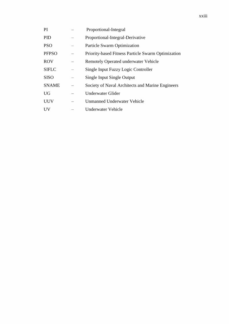
xxiii
PI – Proportional-Integral
PID – Proportional-Integral-Derivative
PSO – Particle Swarm Optimization
PFPSO – Priority-based Fitness Particle Swarm Optimization
ROV – Remotely Operated underwater Vehicle
SIFLC – Single Input Fuzzy Logic Controller
SISO – Single Input Single Output
SNAME – Society of Naval Architects and Marine Engineers
UG – Underwater Glider
UUV – Unmanned Underwater Vehicle
UV – Underwater Vehicle
xxiv
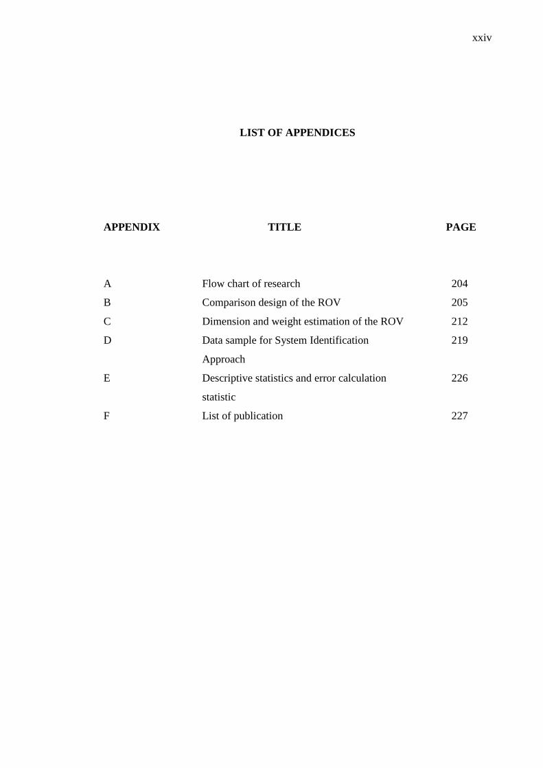
LIST OF APPENDICES
APPENDIX TITLE PAGE
A Flow chart of research 204
B Comparison design of the ROV 205
C Dimension and weight estimation of the ROV 212
D Data sample for System Identification 219
Approach
E Descriptive statistics and error calculation 226
statistic
F List of publication 227
CHAPTER 1
INTRODUCTION
1.1 Introduction
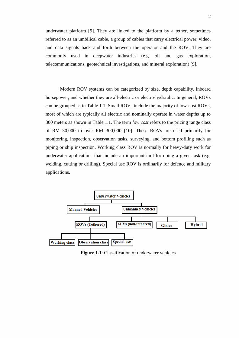
Underwater vehicles (UV) can be classified into two basic categories:
manned underwater vehicles (MUV) and unmanned underwater vehicles (UUV).
UUV is the term referring to unmanned vehicles for underwater application (e.g.
remotely operated vehicles (ROV), autonomous underwater vehicles (AUV),
underwater glider (UG), and hybrid underwater vehicles (HUV). The classification
of UUV is shown in Figure 1.1. These types of UUVs normally have complex
vehicle control systems [1- 4]. These UUVs have existed for over 100 years and have
been known as an interesting area for researchers and industries, especially for
underwater tasks and works [5]. UUVs can bring an important tool in pilot-free
underwater operations due to the increased operating range and depth [6]. Typical
applications of UUVs today include surveying, monitoring, searching, surveillance,
reconnaissance, inspection, recovery, repair maintenance, and construction [7].
Predominantly, in the offshore industry, UUVs have become very important for
underwater works [8].
The ROV is tethered and sometimes called as unmanned underwater robot
and sometimes can be called a remotely operated underwater vehicle to distinguish it
from remote control vehicles operating on an underwater platform. ROVs are
unoccupied, highly manoeuvrable and operated by a person aboard ship or on an
2
underwater platform [9]. They are linked to the platform by a tether, sometimes
referred to as an umbilical cable, a group of cables that carry electrical power, video,
and data signals back and forth between the operator and the ROV. They are
commonly used in deepwater industries (e.g. oil and gas exploration,
telecommunications, geotechnical investigations, and mineral exploration) [9].
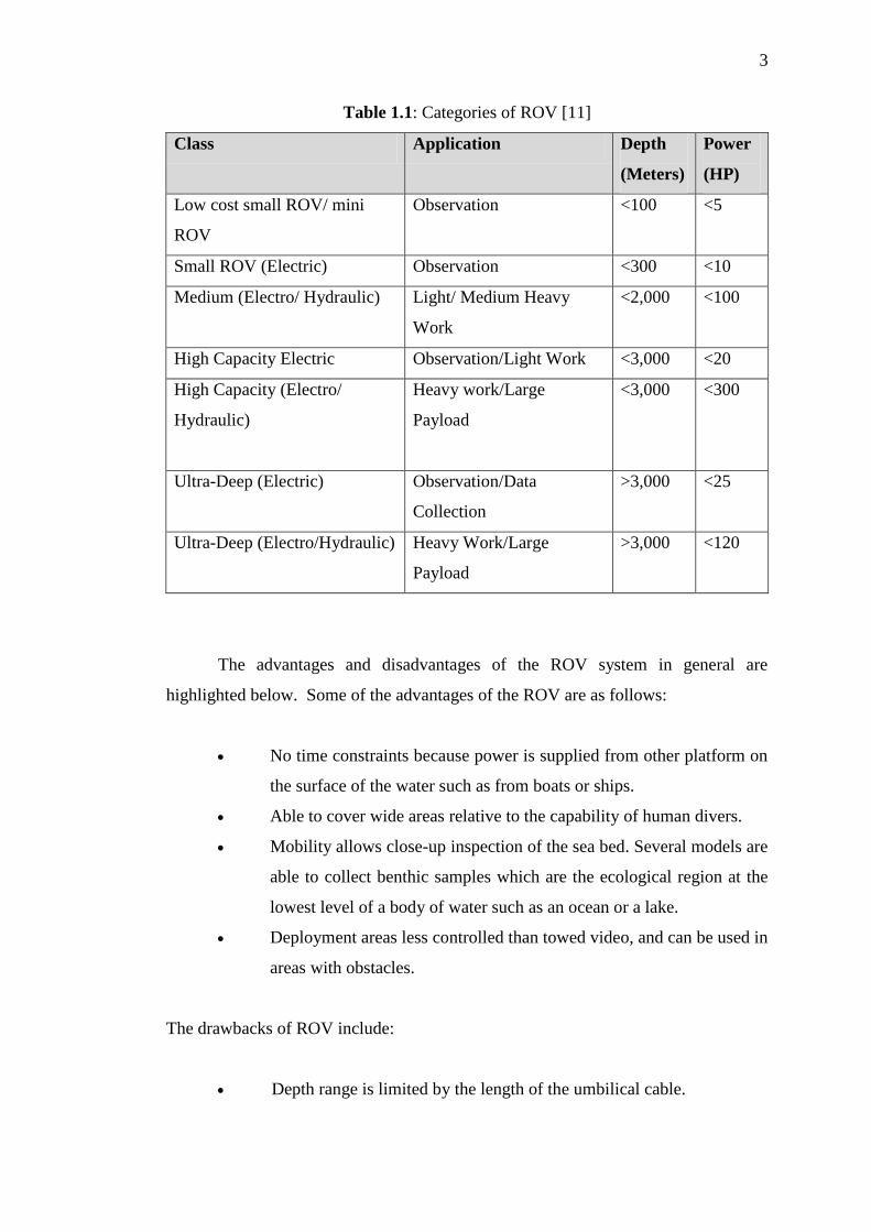
Modern ROV systems can be categorized by size, depth capability, inboard
horsepower, and whether they are all-electric or electro-hydraulic. In general, ROVs
can be grouped as in Table 1.1. Small ROVs include the majority of low-cost ROVs,
most of which are typically all electric and nominally operate in water depths up to
300 meters as shown in Table 1.1. The term low cost refers to the pricing range class
of RM 30,000 to over RM 300,000 [10]. These ROVs are used primarily for
monitoring, inspection, observation tasks, surveying, and bottom profiling such as
piping or ship inspection. Working class ROV is normally for heavy-duty work for
underwater applications that include an important tool for doing a given task (e.g.
welding, cutting or drilling). Special use ROV is ordinarily for defence and military
applications.
Figure 1.1: Classification of underwater vehicles
3
Table 1.1: Categories of ROV [11]
Class Application Depth
(Meters)
Power
(HP)
Low cost small ROV/ mini
ROV
Observation <100 <5
Small ROV (Electric) Observation <300 <10
Medium (Electro/ Hydraulic) Light/ Medium Heavy
Work
<2,000 <100
High Capacity Electric Observation/Light Work <3,000 <20
High Capacity (Electro/
Hydraulic)
Heavy work/Large
Payload
<3,000 <300
Ultra-Deep (Electric) Observation/Data
Collection
>3,000 <25
Ultra-Deep (Electro/Hydraulic) Heavy Work/Large
Payload
>3,000 <120
The advantages and disadvantages of the ROV system in general are
highlighted below. Some of the advantages of the ROV are as follows:
No time constraints because power is supplied from other platform on
the surface of the water such as from boats or ships.
Able to cover wide areas relative to the capability of human divers.
Mobility allows close-up inspection of the sea bed. Several models are
able to collect benthic samples which are the ecological region at the
lowest level of a body of water such as an ocean or a lake.
Deployment areas less controlled than towed video, and can be used in
areas with obstacles.
The drawbacks of ROV include:
Depth range is limited by the length of the umbilical cable.
4
Equipments and sensors need a platform to operate. The ROV may be
unable to access very shallow water.
Equipments or sensors for underwater are very expensive and not
widely available.
It may be difficult to employ in areas with strong water currents or big
waves.
Areas for observation are selected by the operator.
1.2 Research Background
The control system of an ROV is an interesting and challenging problem.
This is primarily due to the difficult and unpredictable environmental conditions that
existed underwater [12]. During operation, the ROV undergoes a complex multi-axis
motion trajectories that are highly nonlinear because the subsystems in the ROV are
ill-defined and strongly coupled with one another [13]. Furthermore, the ROV
dynamics can change considerably with the changes in surrounding conditions and
external disturbances (e.g. wind velocity, ocean currents and waves) [14]. The
hydrodynamic coefficients are difficult to measure or predict accurately [15].
Effective control schemes require relevant signals in order to accomplish the desired
positions and velocities for the ROV. Designing a suitable controlling method of the
ROV is challenging due to the unpredictable nature of underwater dynamics and
difficulty in measuring ROV parameters [16]. In this research, the focused area was
controlling an ROV in a heave-axis motion trajectory sometimes called depth motion
to maintain its desired position. The function of heave-axis motion is to maintain the
ROV position at a specific depth and ensuring its stability, which is also called
station keeping or auto-depth control. This auto- depth control approach is used to
maintain a position in relation to other moving ROV as it tries to remain stationary at
a certain depth in automatic control after this depth is set by the operator.
5
For vertical trajectory, overshoot in the system response will be one of the
factors to be measured because overshoot is particularly dangerous in the ROV
vertical trajectory and may cause damages to both the ROV and the inspected
structure (e.g. operating in cluttered environments). To limit the overshoot, a first
possibility is to pre-filter the input signal [17]. In [18 - 19], they proposed a station
keeping method based on direct method to compute the ROV motion directly from
spatio-temporal image derivatives. In [20], methods to stabilize underwater ROV
movement’s parameter under the presence of environment disturbance are
highlighted. The design of the controller is to keep the amplitude of the overshoot in
the system response drastically limited to a depth set point change, while keeping the
system response time reasonably contained. Reasons for that are, as already pointed
out, the necessity of assuring ROV integrity while operating near to bottom or in
proximity of submersed installations and the need to prevent possible cable stress
(for ROV), without compromising the system efficiency.
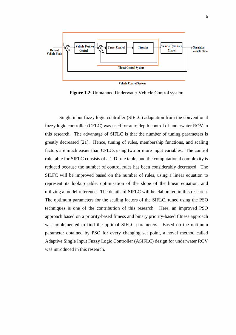
The control system of an ROV can be divided into two different groups as
shown in Figure 1.2. The first group is focused on thrusters control system design
and modelling. The second group is based on overall ROV control system design
and modelling. In this work, the modelling of these two different groups of control
systems will be by using system identification technique. The model will then be
compared with its mathematical model derived from fundamentals. There are two
types of the controller scheme to be investigated in this research: conventional,
followed by an intelligent control scheme. The conventional approach considered PI
and PID techniques, and optimal control linear-quadratic regulator (LQR) approach.
While the intelligent one will focus on adaptation of Fuzzy Logic Controller (FLC)
to control the overall system dynamics. The control algorithm was implemented and
simulated using MATLAB® Simulink.
6
Figure 1.2: Unmanned Underwater Vehicle Control system
Single input fuzzy logic controller (SIFLC) adaptation from the conventional
fuzzy logic controller (CFLC) was used for auto depth control of underwater ROV in
this research. The advantage of SIFLC is that the number of tuning parameters is
greatly decreased [21]. Hence, tuning of rules, membership functions, and scaling
factors are much easier than CFLCs using two or more input variables. The control
rule table for SIFLC consists of a 1-D rule table, and the computational complexity is
reduced because the number of control rules has been considerably decreased. The
SILFC will be improved based on the number of rules, using a linear equation to
represent its lookup table, optimisation of the slope of the linear equation, and
utilizing a model reference. The details of SIFLC will be elaborated in this research.
The optimum parameters for the scaling factors of the SIFLC, tuned using the PSO
techniques is one of the contribution of this research. Here, an improved PSO
approach based on a priority-based fitness and binary priority-based fitness approach
was implemented to find the optimal SIFLC parameters. Based on the optimum
parameter obtained by PSO for every changing set point, a novel method called
Adaptive Single Input Fuzzy Logic Controller (ASIFLC) design for underwater ROV
was introduced in this research.
7
1.3 Problem Statement and Significance of the Research
The problem statement was found after a lot of investigations done in recent
and existing works and several case studies based on journals, conference papers,
thesis, books and other literature. In this research, the major problem considered in
the ROV is in designing its depth control system. All UUV faced the same problem
when controlling the vehicle since underwater environment is unexpected and
unpredictable. The list of problems for ROV control include pose recovery or station
keeping, under actuated condition, coupling issues and also communication
technique. As the scope of study is limited to the control system for station keeping
(depth control), the other problems will not be discussed further except in future
work’s recommendation. The aim of this project is more on controlling an ROV to
maintain its depth.
In most ROV, its pitch and roll motion are stabilized through the inherent
hydrostatic characteristic of the construction itself. The control system should deal
only with the depth, z-axis, the Cartesian positions x- and y-axis, and with the yaw
angle. In general the uncontrolled angles for roll and pitch motions remain small and
the depth can be decoupled from the other coordinates [22]. Maintaining the position
of the small scale ROV within the working area is a difficult task especially in the
presence of underwater currents, wave and wind even for experienced pilots [22].
ROV has been designed to be passively stable in pitch and roll (its centre of gravity
is below the centre of buoyancy). For this reason, rolling and pitching motion of the
ROV are very small, and therefore better results are obtained with a similarity
motion model.
The function of depth control is to maintain the ROV position at a specific
depth and ensuring its stability, which is also called station keeping mode. For depth
control, overshoot in the system response will be one of the issues occurred because
overshoot is particularly dangerous for the ROV in its vertical trajectory and may
cause damages to both the ROV and the inspected structure. Overshoot reduction is
8
actually achieved at the expense of increased rise time [23]. In general, the control
objective is to obtain a limited or no overshoot in system response without penalizing
the rise time. This is difficult to achieve since normally, the limitation of overshoot
in system response can be obtained but the rise time will be slower. From the review
of existing works, there seems to be very few literatures that look at optimizing ROV
controller parameters at different operating conditions and then derive an adaptation
law for the ROV to allow automatic change of optimum sets of parameters
depending on different situations (see Section 2.3). One main motivation of this
research is in the areas of optimization and adaptation of controller parameters.
Adapting the optimized ROV controller parameters at different set point conditions
may very well improve its performance in terms of reducing its overshoot and
response time for depth control. This seems a problem worthy of further
investigation.
The derivation of mathematical model of a UUV is a complex problem. It is
difficult to delimitate or calculate many parameters, which has to be well known to
solve the dynamic equations of UUV movement. Accurate dynamic model are
crucial to the realization of ROV simulators, precision autopilots and for prediction
of performances. Control of underwater vehicles is not easy, mainly due to the
nonlinear and coupled characters of plant equations and also the lack of precise
models of underwater vehicle hydrodynamics and uncertainty parameters, as well as
the appearance of environmental disturbances [24] such as wind, current and wave.
Many of the researchers have to ignore some uncertainties in the parameters to
reduce the difficulty in designing the controller. The assumptions on the dynamics
of ROV in deriving its mathematical model are the most common approach.
Implementation of the controller on the ROV using FLC itself poses its own level of
complexity. Consequently, implementation of FLC also demands for fast and high-
performance processors. For SIFLC approach, there are many parameters to be
tuned manually in the literature [21]. Trial an error method will be used to find the
optimum parameter. In [21], the parameters has been reduced to two, to be tuned
manually using trial and error. Consequently, it will take more execution time to
find the optimum parameters. Another issue is that the SIFLC has never been tested
experimentally on any UUV.
9
1.4 Objectives of the Research
The objectives of this research are:
1) Development and modelling of thrusters for a prototype ROV using
system identification technique for vertical trajectory. Then, the
system identification model will be compared with its mathematical
model derived using ROV fundamentals.
2) Designing an intelligent auto-depth control algorithm in the ROV
vertical trajectory that can guarantee no overshoot in the system
response and having faster rise and settling time.
3) Optimizing the parameters of improved SIFLC using PSO techniques
based on Priority-based Fitness PSO (PFPSO) and Binary Priority-
based Fitness PSO (BPFPSO) approach.
4) Designing an Adaptive Single Input Fuzzy Logic Controller
(ASIFLC) for depth control of a newly fabricated underwater ROV to
improve overall performance for different set points and test the
algorithm experimentally.
1.5 Research Scopes
The k-chartTM
of the research can be referred to in Appendix 1. From the k-
chartTM
, the focus and aim to of this research can be identified so that they are
aligned with research objectives as explained in the previous section. The focus of
this work has been highlighted in this chart which mainly deals in the area of control
input for ROV. In this project, the focus was in controlling an ROV in a heave-axis
10
motion to maintain its desired position. The objective was to develop an intelligent
controller that can guarantee the suppression or at least the limitations of overshoot
in the system response. This project identified an empirical model of a newly
designed ROV and then developed an intelligent controller to stabilize the ROV.
This project began with mathematical and empirical modelling to illustrate the
dynamics of the underwater vehicle followed by an intelligent controller design.
Empirical modelling refers to any kind of computer modelling based on experimental
observations rather than on mathematical describable relationships of the system.
Mathematical modelling is a description of a system using mathematical concepts.
Development of mathematical modelling of this research was based on several
assumptions made by [15] on the dynamics equation of ROV to reduce the
complexity and simplify the dynamics motion equation of ROV. The
implementation phase was verified through MATLAB® and Simulink platform. The
verified algorithms were then tested on the actual prototype ROV.
The emphasis of this project is on the aspect of controlling the ROV to
investigate the problem of depth control system as mentioned before. The objective
in modelling a depth controller is to develop an accurate model representing the
actual system dynamics. The motion of the underwater vehicle consists of two
movements; vertical and horizontal motion. However, the scope of this project is
only concerned on the dynamics in the vertical motion considered in the auto-depth
control approach. Open frame ROV design was developed because this
configuration has been widely adopted by commercial ROV. This is because of its
simplicity, robustness, easy to maintain, more stable compared with closed hull and
cheaper. Although the hydrodynamics of the open frame vehicles are known to be
less efficient than that of closed hull type’s ROVs, the open frame ROV is suitable
for applications that does not require movements at high velocities or travelling long
distance. This open frame ROV design also focused on auto-depth control operation
modes. This auto-depth control approach was used to maintain a position in relation
to other moving ROV as it tries to remain stationary at a certain depth so that the
ROV can do a task (e.g. monitoring pipe crack, welding, and pick and place) at a
certain time. The ROV maintained a fixed position in relation to a fixed object. The
depth of testing conducted is within the available water depth of 1-5 meter (e.g. lab
11
test and pool test). For depth control, overshoot in the system response are
particularly dangerous. Clearly an overshoot in the ROV vertical trajectory may
cause damages to both the ROV and the inspected structure especially when
operating in a cluttered environment. Control objective is to eliminate overshoot and
reduce rise time and settling time in the system response.
1.6 Contribution of the Research Work
The contributions of this research are:
1) Development and modelling of thrusters and ROV using the system
identification technique for vertical trajectory of a newly fabricated ROV.
Validation between mathematical modelling and system identification of
the prototype ROV has been done in simulation and in actual
experimental works.
2) Designing an intelligent depth control algorithm for the ROV model in
MATLAB. The focus was on an improved Single Input Fuzzy Logic
Controller (SILFC). Investigations on the number of rules, lookup table,
slope of the linear equation, and model reference to give best
performances for ROV depth control having no overshoot in system
response and faster rise time and settling time has been done.
3) Optimizing the SIFLC parameters using Particle Swarm Optimization
(PSO) techniques. An improved PSO algorithm is based on a Priority-
based Fitness PSO (PFPSO) and Binary Priority-based Fitness PSO
(BPFPSO) approach is implemented for finding optimal SIFLC
parameters.
12
4) Adaptive Single Input Fuzzy Logic Controller (ASIFLC) has been
designed and tested to account for the different optimum parameters
based on different depth set point. A method to dynamically combine the
result of different optimized parameter settings obtained from PSO
optimisation for different set point values has been suggested and tested.
ASIFLC design for auto-depth control of the ROV was found to give
better performance in system responses and can adapt to changes in the
set point.
1.7 Organization of the Thesis
This thesis is organized into five chapters. Their contents are outlined as
follows:
Chapter 1 provides an introduction to the ROV system and research
background. In this chapter, the objectives, scopes and contribution of this research
are provided. The problem statement of this study is also covered under this chapter.
Chapter 2 provides an extensive review of modelling and control techniques
used to control the UUVs especially the ROV. The details of depth control of UUV
are covered in this chapter which include a critical review of ROV depth control
from existing works. In this chapter, the fundamentals of system identification
techniques, fuzzy logic and the Single Input Fuzzy Logic Controller were discussed.
Next, the stochastic optimization approach, namely the particle swarm optimization
approach was discussed. Finally, the specification of the underwater platform used in
this research will be explained briefly in this chapter.
Chapter 3 discusses the methodology of the project including the modelling
of the thrusters and the ROV using system identification approach. The factors
13
affecting the control design of ROV is covered within this chapter. It also contains
the overview of the ROV system and the derivation of the mathematical model of
system dynamics based on the several assumptions made of the dynamics equation of
the ROV. In this chapter, the design of SIFLC and an improved SIFLC for ROV
using MATLAB®/Simulink was also described. The focus is on improved SILFC
where it investigates the effects of scaling factor tuning for SIFLC to improve the
performances of system response for depth control. Also, the optimization method
for tuning SIFLC by using Particle Swarm Optimization (PSO) approach is
introduced for finding optimal SIFLC parameters. Furthermore, it includes the
comparison of SIFLC with conventional PID controller and Output Feedback
Observer tuning using Linear-Quadratic Regulator (LQR). The controller design
focused on depth control of the ROV and performance evaluation is presented.
Finally, a new method called Adaptive Single Input Fuzzy Logic Controller
(ASIFLC) was proposed. The ASIFLC was designed for depth control of the ROV
and this technique gives best performances in system response and can adapt to any
changing values of set point. This chapter also includes the comparison with real
time application and other ROV with the same class.
Chapter 4 analyze thoroughly the results based on the methodologies
described and implemented in Chapter 3. The results of system identification and
mathematical modelling were covered in this chapter. Also, the results of
investigations in improving SIFLC and the parameters of SIFLC by tuning using
priority based fitness PSO and binary priority based fitness PSO was reported here.
Finally, the results of using a new method called the ASIFLC was discussed and
found to give better performances in system response. The method is suitable to be
implemented in real time system due to its reduced complexity and can easily be
realized using a low cost microprocessor or microcontroller.
Chapter 5 concludes the work undertaken by summarizing the system,
highlighting the results and contributions and providing several suggestions for
future work.
14
1.8 Summary
This chapter gives an introduction of the ROV and also research background
of the ROV in section 1.2. Also discussed a problem statement and significant of the
research in section 1.3. In this chapter objectives, scopes and contributions of the
research work was provided (section 1.4 -1.6).
195
REFERENCES
1. Robert D. Christ and Robert L. Wernli Sr. The ROV Manual: A User Guide for
Observation-Class Remotely Operated Vehicles, Elsevier Ltd., Oxford UK. First
edition. 2007.
2. Gianluca Antonelli, Underwater Robots: Motion and Force Control of Vehicle-
Manipulator Systems. Springer, Cassino Italy. Second Edition. 2006.
3. Roy Kim Lea. Control of a Tethered Underwater Flight Vehicle. PhD. Thesis.
University of Southampton. May 1998.
4. Louis Andrew Gonzalez. Design, Modelling and Control of an Autonomous
Underwater Vehicle. B.Eng. thesis. The University of Western Australia.
October 2004.
5. Thor. I. Fossen. Nonlinear Modelling and Control of Underwater Vehicles. PhD
Thesis. Norwegian Institute of Technology. 1991.
6. Abkowitz, M.A. Stability and Motion Control of Ocean Vehicles. The MIT
Press, Cambridge, 1969.
7. J.C. Kinsey, R.M. Eustice, and L.L. Whitcomb. Underwater Vehicle Navigation:
Recent Advances and New Challenges. Conference on Manoeuvring and
Control of Marine Craft. Lisbon, Portugal, 2006.
8. K.R. Goheen and E.R. Jefferys. The application of alternative modelling
techniques to ROV dynamics. Proceedings of IEEE International Conference
Robotics and Automation. 1990. vol. 2. 1302-1309.
9. Robert D. Christ and Robert L. Wernli Sr. The ROV Manual: A User Guide for
Observation-Class Remotely Operated Vehicles, Elsevier Ltd., Oxford UK.
Second Editions. 2013.
10. Robert E. Pacunski, Wayne A. Palsson, H. Gary Greene, and Don Gunderson.
Conducting Visual Survey with a Small ROV in Shallow Water. Marine Habitat
Mapping Technology for Alaska. 2008. 109-128.
11. NORSOK Standard. Remotely Operated Vehicle (ROV). Norwegian Technology
centre. 1st October 2003.
196
12. Hou, C. S. The effects of the umbilical cable and current on the motion of the
underwater remotely operated vehicle. Master thesis. National Cheng
University. China. 2005.
13. A. M. Plotnik and S. M. Rock. A multi-sensor approach to automatic tracking of
midwater targets by an ROV. Proceedings of the American Institute of
Aeronautics and Astronautics (AIAA), 2007.
14. Louis Andrew Gonzalez. Design, Modelling and Control of an Autonomous
Underwater Vehicle. Master Thesis. University of Western Australia. 2007.
15. C.S. Chin, S.H. Lum. Rapid modeling and control systems prototyping of a
marine robotic vehicle with model uncertainties using xPC target system, Ocean
Engineering, 2011. Elsevier, The Netherlands. Vol. 38 (17‐18). 2128–2141.
16. Damian Matthews, Janelle Draubay, Ty Nowotny, Ben Creed, UC Davis. Aggie
Deep ROV Technical Report. Mechanical and Electrical Department, College of
Engineering. 2008.
17. Astrom K.J., Hagglund T., Hang C. C. and Ho W. K. Automatic Tuning and
Adaptation for PID controllers - a survey. Control Engineering Practice. 1993.
Vol. 1(4). 699 – 714.
18. S. Negahdaripour and J. Fox. Underwater Optical Station-Keeping : Improved
Methods. Journal of Robotic Systems. 1991. Vol.8(3). 319-338.
19. L. Jin, X. Xu, and S. Negahdaripour. A Real-Time Vision-Based Station
Keeping System for Underwater Robotics Applications. Proceeding of the
MTS/IEEE Oceans Conference. 1996. Vol. 3. 1076-1081.
20. Andrzej Zak, Fuzzy Controller for Underwater Remotely Operated Vehicle
which is Moving in Conditions of Environment Disturbance Occurrence.
Journal of KONES Power train and Transport. 2011. Vol. 18(2). 499- 507.
21. Kashif Ishaque, S. S. Abdullah, S. M. Ayob and Z. Salam. Single Input Fuzzy
Logic Controller for Unmanned Underwater Vehicle. Journal of Intelligent and
Robotic Systems. 2010. Vol. 59. 87-100.
22. Edwin Kreuzer and Fernando C. Pinto. Controlling the Position of a Remotely
Operated Underwater Vehicle. Applied Mathematics and Computation. 1996.
Vol. 78. 175- 185.
23. J.V. Klump, R.W. Paddock, J.G. Babb and P.J. Auster. The Evolution and
Development of the Small ROV as an Essential Experimental Tool in
197
Limnological and Coastal Marine Research. IEEE Conference and Exhibition
(OCEANS). 2001. Vol. 2. 826-832.
24. Humphreys, D.E. and Watkinson, K.W. Hydrodynamic Stability and Control
Analyses of the UNH-EAVE, Autonomous Underwater Vehicle, Marine Systems
Lab. Report, Univ. of New Hamp., Durham. 1982.
25. A. Lamas, F. Lopez Pena, and R.J. Duro. A hybrid Approach for Designing the
Control System for Underwater Vehicles. Spriger-Verlag, Berlin Heideilberg.
2009. 88-95.
26. Serder Soylu, Bradley J. Buckham and Ron P. Podhurodeski. Dynamics and
Control of tethered Underwater Manipulator Systems. IEEE Publisher. 2010. 1-
8.
27. P. Maurya, E. Desa, A. Pascoal, E. Barros, G.S. Navelkar, R. Madhan,
A.A.M.Q. Mascarenhas, S. Prabhudesai, S. Afzulpurkar, A. Gouveia, S.Naroji,
and L. Sebastiao, Control of the Maya AUV in the Vertical and Horizontal
Planes: Theory and Practical Results, 7th IFAC Conference on Manoeuvring and
Control of Marine Craft. 2007. 1-5.
28. Leif Christensen, Peter Kampmann, March Hildebrandt, Jan Albiez, and Frank
Kireshner. Hardware ROV Simulation Faciliting for the Evaluation of Novel
Underwater Manipulation Techniques. IEEE Publisher. 2009. 1 -8.
29. Wei Wang. Autonomous Control of a Differential Thrust Micro ROV. Master
Thesis. University of Waterloo, Ontario, Canada. 2006.
30. Manecius Selvakumar Joseph, Atmanand M.A. , Ramadass G.A., Ramesh Raju,
and Jayakumar V.K.. Navigation and Position Control of Underwater Vehicle
(ROSUB 6000). 13th
FIRA Robot World Congress. 2010. 25-32.
31. Eduardo Sebastian. Adaptive Fuzzy Sliding Mode Controller for the Snorkel
Underwater Vehicle. 9th
International Conference on Simulation of Adaptive
Behavior. 2006. 855-866.
32. Dana R. Yoerger, John G. Cooke, Jean-Jacques E. Slotine. The Influence of
Thruster Dynamics on Underwater Vehicle Behavior and Their Incorporation
Into Control System Design. IEEE Journal of Ocean Engineering. 1990. Vol. 15
(13). 167-178.
33. Naomi Ehrich Leonard. Stability of a Bottom-heavy Underwater Vehicle.
Automatica. 1997. Vol. 33(3). 331-346.
198
34. Yoerger, D.R., Slotine, J. J.E. Robust Trajectory Control of Underwater
Vehicles. IEEE Journal of Oceanic Engineering. 1985. 462 – 470.
35. T.I. Fossen. Guidance and control of ocean vehicles. Wiley. New York. 1994.
36. M.S Triantafyllou and M.A Grosenbaugh. Robust Control for Underwater
Vehicle Systems with Time Delays. IEEE Journal of Ocean Engineering. 1991.
Vol. 16 (1). 146-151.
37. Faruq, Amrul, S.S Abdullah, M.Fauzi and S. Nor. Optimization of depth control
for Unmanned Underwater Vehicle using surrogate modelling technique. 4th
International Conference on Modeling, Simulation and Applied Optimization.
2011.
38. Kashif Ishaque. Intelligent Control of Diving System Of An Underwater Vehicle.
Master Thesis. Universiti Teknologi Malaysia. 2009.
39. M. Santhakumar and T. Asokan. A Self-Tuning Proportional-Integral-Derivative
Controller for an Autonomous Underwater Vehicle, Based On Taguchi Method.
Journal of Computer Science. 2010. Vol. 6 (8). 862-871.
40. Smallwood, D.A. & Whitcomb, L. L. Model-based dynamic positioning of
underwater robotic vehicles: theory and experiment. IEEE Journal of Oceanic
Engineering. 2004. Vol. 29(1) .169 – 186.
41. Chen Siong Chin, Micheal Wai Shing Lau, Eicher Low and Gerald Gim Lee
Seet. Robust Controller Design Method and Stability Analysis of an
Underactuated Underwater Vehicle. International Journal Applied Mathematics
and Computer Sciences. 2006. Vol. 16(3). 345-356.
42. Kamarudin, M.Nizam, S.Md. Rozali, and A.Rashid Husain. Observer-Based
Output Feedback Control with Linear Quadratic Performance. Procedia
Engineering. 2013. Vol. 53. 233-240.
43. C. Han Ho. Output Feedback Variable Structure Control Design with an
Performance Bound Constraint. Automatica. 2008. Vol. 44. 2403-2408.
44. S. K. Bag. Output Feedback Sliding Mode Design for Linear Uncertain Systems.
IEEE Proceedings - Control Theory and Applications. 1997. Vol. 144. 209-216.
45. O. Hassanein. Sreenatha G. Anavatti, Tapabrata Ray. Fuzzy Modelling and
Control for Autonomous Underwater Vehicle, 5th
International Conference on
Automation Robotics and Applications, IEEE. 2011. 169-174.
46. Yang Shi, Weiqi Qian, Weisheng Yan and Jun Li. Adaptive Depth Control for
Autonomous Underwater Vehicles Based on Feedforward Neural Networks.
199
International Journal of Computer Science & Applications, 2007. Vol. 4
(3).107-118.
47. Gianluca Antonelli, Stefano Chiaverini, Nilanjan Sarkar, and Micheal West.
Adaptive Control of an Autonomous Underwater Vehicle : Experimental Results
on ODIN. IEEE Transactions on Control System Technology. 2001.Vol. 9 (5).
756-765.
48. Choi, B. J. Design of Single-Input Direct Adaptive Fuzzy Logic Controller
(SDAFLC). International Journal of Fuzzy Logic and Intelligent Systems. 2001.
Vol. 1(1). 44- 49.
49. A.S. Mohd. Nor, S.S. Abdullah, M.S.M. Aras and M.Z.A Rashid. Neural
Network Predictive Control (NNPC) of a Deep Submergence Rescue Vehicle
(DSRV), 4th International Conference on Underwater System Technology:
Theory and Application. 2012. 24- 29.
50. Zhijie Tang, Luojun and Qingbo He. A Fuzzy-PID Depth Control Method with
overshoot Suppression for Underwater Vehicle. International Conference on
Life System Modeling and Simulation and International Conference on
Intelligent Computing for Sustainable Energy and Environment (LSMS/ICSEE).
2010, Part II, LNCS 6329. 218-224.
51. Qian Liu, Daqi Zhu, and Simon X. Yang. Unmanned Underwater Vehicles Fault
Identification and Fault-Tolerant Control Method based on FCA-CMAC Neural
Networks: Applied on a Actuated Vehicle. Journal of Intelligent & Robot
Systems. 2012.Vol. 66(4). 463-475.
52. Tomas. Salgado-Jamenez, Luis G. Garcia-Valdovinos and Guillermo Delgado-
Ramirez. Control of ROVs using a Model-free 2nd
-Order Sliding Mode
Approach, Sliding Mode Control. InTech Publisher. 347-368.
53. Shahriar Negahdaripour, Sohyung Cho and Joon Young Kim. Controller Design
for an Autonomous Underwater Vehicle using Nonlinear Observers.
International Journal of Ocean Engineering. 2011. Vol. 1(1), 16- 27.
54. Faruq, Amrul, Abdullah, Shahrum Shah and Fauzi Nor Shah, M. Optimization
of an Intelligent Controller for an Unmanned Underwater Vehicle. Telkomnika.
2011. Vol. 9 (2), 245-256.
55. M.H. Saghafi, H. Kashani, N. Mozayani, and G. R. Vossoughi. Developing a
Tracking Algorithm for Underwater ROV using Fuzzy Logic Controller. 5th
Iranian Conference on Fuzzy Systems. 2004. 17-25.
200
56. Maria Letizia Corradini, Andrea Monteriu, and Giuseppe Orlando. An Actuator
Failure Tolerant Control Scheme for an underwater Remotely Operated Vehicle.
IEEE Transactions on Control Systems Technology. 2011. Vol. 19 (5). 1036 –
1046.
57. Zhijie Tang, Jun Luo, and Shaorong Xie. A Novel Attitude Control Method for
ROV. Journal of Computational Information Systems. 2010. Vol. 6(6). 1837-
1842.
58. Wallace M. Bessaa, Max S. Dutra, and Edwin Kreuzer. Depth control of
Remotely Operated Underwater Vehicles using an Adaptive fuzzy sliding model
controller. Robotics and Automation Systems. 2008. Vol. 56 (8). 670 – 677.
59. Sergio M. Savaresi, Fabio Previdi, Alessandro Dester, Sergio Bittanti, and
Antonio Ruggeri. Modeling, Identification, and Analysis of Limit-Cycling Pitch
and Heave Dynamics in an ROV. IEEE Journal Of Oceanic Engineering. 2004.
Vol. 29 (2). 407-417.
60. Silvia M. Zanoli and Guiseppe Conte. Remotely Operated Vehicle Depth
Control. Control Engineering Practice. 2003. Vol. 11. 453- 459.
61. S.D. Joshi, and D.B. Talange. Performance Analysis : PID and LQR Controller
for REMUS Autonomous Underwater Vehicle (AUV) Model. International
Journal of Electrical Engineering & Technology. 2012. Vol. 3(2). 320-327.
62. Nima Harsamizadeh Tehrani, Mahdi Heidari, Yadollah Zakeri, Jafar Ghaisari.
Development, Depth Control and Stability Analysis of an Underwater Remotely
Operated Vehicle (ROV). 8th IEEE International Conference on Control and
Automation. 2010. 814 – 819.
63. Kevin A’Hearn and Robert Coppolino. A system Identification Method for
Simplifying Dynamics Equations of Motion for Remotely Operated Vehicles
and Towed Systems. IEEE Publisher. 2000. 525-530.
64. Goheen, K.R and Jefferys, E.R. The application of alternative modeling
techniques to ROV dynamics. IEEE International Conference on Robotic and
Automation. 1990. Vol.2. 1302 -1309.
65. Clark, L., Goheen, K.R, and Yoerger D.R. Practical experiment in ROV system.
IEEE Conference on American Control. 1993. 575 – 579.
66. Patrik Johansson and Jacob Bernhard. Advanced Control of a Remotely
Operated Underwater Vehicle. Master Thesis. Department of Electrical
Engineering Linköpings universitet. 2012.
201
67. K. Ishaque, S.S. Abdullah, S.M. Ayob, Z. Salam. A simplified approach to
design fuzzy logic controller for an underwater vehicle. Ocean Engineering.
Elsevier Amsterdam, The Netherlands. 2010.1 –14.
68. M. Amjad, Ishaque K., Abdullah S.S. and Salam Z. An alternative approach to
design a Fuzzy Logic Controller for an autonomous underwater vehicle. IEEE
Conference on Cybernetics and Intelligent Systems. 2010. 195 -200.
69. Choi, B. J., Kwak, S. W., and Kim, B. K. Design and Stability Analysis of
Single-Input Fuzzy Logic Controller. IEEE Transaction on Systems, Man and
Cybernetics-Part B: Cybernetics. 2000. Vol. 30 (2). 303-309.
70. Viswanathan, K., Oruganti, R., and Srinivasan, D. Nonlinear Function
Controller: A Simple Alternative to Fuzzy Logic Controller for a Power
Electronic Converter. IEEE Transaction on Industrial Electronics. 2005. Vol.
52(5). 1439-1448.
71. Arulselvi, S., and Uma, G. Development of Simple Fuzzy Logic Controller for
Extended Period-ZCS/ZVS-Quasi Resonant converter: Design, Simulation, and
Experimentation. Journal of Circuits, Systems, and Computers. 2006. Vol.
15(5). 757-776.
72. Ayob S. M., N. A. Azli and Z. Salam. PWM DC-AC Converter Regulation
using a Multi-Loop Single Input Fuzzy PI Controller. Journal of Power
Electronics. 2009. Vol. 9(1). 124-131.
73. M.A. Ahmad, M.S. Saealal, R.M.T. Raja Ismail, M.A. Zawawi, A.N.K. Nasir,
and M.S. Ramli. Single Input Fuzzy Controller With Command Shaping
Schemes For Double-Pendulum-Type Overhead Crane. Global Conference on
Power Control and Optimization. 2010. 1-5.
74. Kennedy, J. and Eberhart, R. Particle Swarm Optimization. Proceedings of the
IEEE International Conference on Neural Networks. 1995. 1942-1948.
75. E. J. Solteiro Pires, J. A. Tenreiro Machado and P. B. de Moura Oliveira.
Particle Swarm Optimization: Dynamical Analysis through Fractional Calculus.
Chapter 24, InTech Publisher, 2009.
76. Tae-Hyoung Kim, Ichiro Maruta and Toshiharu Sugie. Robust PID Controller
Tuning Based on Constrained Particle Swarm Optimization. Automatica. 2007.
Vol. 44(4). 1104-1110.
202
77. M. I. Solihin, Wahyudi, M.A.S Kamal and A. Legowo. Optimal PID Controller
Tuning of Automatic Gantry Crane using PSO Algorithm. Proceeding of the 5th
International Symposium on Mechatronics and its Applications. 2008.1-5.
78. Clerc, M. and Kennedy, J. The particle swarm - explosion, stability, and
convergence in a multidimensional complex space. IEEE Transactions on
Evolutionary Computation. 20022. Vol. 6. 158-173.
79. Trelea, I.C. The Paritcle Swarm Optimization Algortihm : Convergence
Analysis and Parameter Selection. Information Processing Letters. 2003. Vol.
85(6). 317 -325.
80. Hazriq Izzuan Jaafar, Nursabillilah Mohd Ali, Z. Mohamed, Nur Asmiza
Selamat, Anuar Mohamed Kassim, Amar Faiz Zainal Abidin, and J.J. Jamian.
Optimal Performance of a Nonlinear Gantry Crane System via Priority-based
Fitness Scheme in Binary PSO Algorithm.IOP Conference Series: Materials
Science and Engineering. 2011. Vol. 53(1). 1 -6.
81. Bai, Q. Analysis of Particle Swarm Optimization Algorithm. Computer Science
and Information Science. 2010. Vol. 3(1). 180 -184.
82. Eberhart, R.C and Shi, Y., Particle Swarm Optimization : Developments,
Applications and Resources, Proceeding of Congress on Evolutionary
Computation, Vol. 1 No.1, pp 81- 86, 2001.
83. Hazriq Izzuan Jaafar, PSO-Tuned PID Controller of a Gantry Crane System.
Master Thesis. University of Technology Malaysia. 2013.
84. Society of Naval Architects and Marine Engineers (SNAME): Nomenclature for
treating the motion of a submerged body through a fluid. Tech. Res. Bull. 1–5,
1950.
85. M.A. Salim, Noordin, A. , and Jahari, A.N. A Robust of Fuzzy Logic and
Proportional Derivative Control System for Monitoring Underwater Vehicles.
2nd
International Conference on Computer Research and Development. 2010.
849 – 853.
86. Thomas Braunl. Design, modelling and simulation of an autonomous underwater
vehicle. International Journal of Vehicle Autonomous Systems. 2006. Vol. 4 ( 2).
106-121.
87. T.H Koh, M.W.S Lau, E. Low, G.Seet, S.Swei, and P.L. Cheng. Development
and Improvement of an Underactuated Underwater Robotic Vehicle. Nanyang
Technological University, Singapore. 2002. 2039- 2044.
203
88. C.S Chin. Systematic Modeling and Model-Based Simulation of a Remotely
Operated Vehicle using MATLAB and Simulink. International Journal of
Modeling Simulation and Scientific Computing. 2011. Vol. 2(4). 481-511.
89. Juan Pablo Julca Avila, Julio Cezar Adamowski, Newton Maruyama, Fabio
Kawaoka Takase, and Milton Saito. Modeling and Identification of an Open-
frame Underwater Vehicle: The Yaw Motion Dynamics. Journal of Intelligent &
Robot Systems. 2012. Vol. 66(1-2). 37-56.
90. Michel Bernier, Ryan T. Foley, Philip Rioux, Amelia Stech. Latis II Underwater
Remotely Operated Vehicle Technical Report . B.s. Mechanical Engineering.
University of Maine, 2010.
91. Yang Shi, Weiqi Qian, Weisheng Yan, and Jun Li. Adaptive Depth Control for
Autonomous Underwater Vehicles Based on Feedforward Neural Networks.
International Journal of Computer Science & Applications. 2007. Vol. 4(3).
107-118.
92. T.H Koh, M.W.S Lau, E. Low, G.Seet, S.Swei, and P.L. Cheng. A Study of The
Control of An Underactuated Underwater Robotic Vehicle. Proceedings of the
2002 IEEE/RSJ. 20002. 2049- 2054.
93. Data sheet Micro-box MathWorksTM
xPC Enabled real-time system. Solutions
4U Sdn. Bhd. http://www.solutions4u-asia.com/PDT/TS/MBox/MBox_files/
S4U%20Microbo x%20Brochure.pdf. 2012.
94. Eric Conrado De Souza, and Newton Maruyama. Intelligent UUVs: Some Issues
on ROV Dynamic Positioning. IEEE Transactions on Aerospace and Electronic
Systems. 2007. Vol. 43(1). 214 -226.
95. Cheng Siong Chin, Micheal W S Lau and Eicher Low. ROV Design Analysis
Version 1.2. Nanyang Technology University (NTU). 2008.
96. David Heeley. Sensor Product Division, Pheonix, Arizona. Understanding
Pressure and Pressure Measurement.
www.freescale.com/files/sensors/doc/app_note/ AN1573.pdf. 2014
97. Yasaman Alborz, Paria Bigdeli, and Arghavan Zarei. The effect of Simplifying
the development of reflect sensor systems to measure rotational parameters.
Majlesi Journal of Mechatronics Systems. 2012. Vol.1(2). 14- 17.
98. Peter Gruber and Silvano Balemi. Overview of non-linear control methods.
Swiss Society for Automatic Control, 2010.
204
99. Phajdak T. , Leahey J. , Crossman M. , and Ferguson R. First Build Report
Group 2: Aquatic Cave Exploration Remotely Operated Vehicle (ACE ROV).
Dalhousie University. 18th
November 2010.
100. Clatsop Community College ROV Club. CCC ROV Project Developing
Dynamic Aquatic Solutions for the Future. 2006.
101. Dembicki M. , and Boshek M. Second Generation ROV: HORNET II. 22th July
2003.
102. Bernier M. , Foley R. T. , Rioux P. , and Stech A. Latis II Underwater Remotely
Operated Vehicle Technical Report. B.s. Mechanical Engineering. University of
Maine. 2010.
103. Abruzini N., Boisvert J. , Dobek K., and Tedeschi A. The SeaWeed Remotely
Operated Vehicle Senior Design Project. Florida Institute of Technology.
Melbourne, FL. 25th
July 2007.
104. S. Watson, Mobile Platforms for Underwater Sensor Networks, PhD Thesis,
University of Manchester, 2012.