Embed Size (px)
Citation preview
8/9/2019 Adaptive load blinder for distance protection.pdf
http://slidepdf.com/reader/full/adaptive-load-blinder-for-distance-protectionpdf 1/7
Adaptive load blinder for distance protection
Hassan Khorashadi Zadeh a,⇑, Zuyi Li b
a Siemens Energy Inc. Transmission Division, 7000 Siemens Road, Wendell, NC 27591, United Statesb Illinois Institute of Technology, Department of Electrical and Computer Engineering, 3301S. Dearborn Street, Chicago, IL 60616, United States
a r t i c l e i n f o
Article history:
Received 2 August 2009
Received in revised form 26 September
2010
Accepted 22 November 2010
Keywords:
Distance relay
Load blinder
Load encroachment
Loadability
Blackout
Artificial neural network
a b s t r a c t
This paper proposes a novel adaptive load blinder for distance protection. A distance relay can provide
remote backup protection by zones 2 and 3, but it may mal-operate under heavy loading conditionsand cause cascading trips in the network, which could further lead to a widespread blackout. To prevent
cascading outages, load blinders or load encroachment elements are generally used to block the distance
relay when there is heavy load in the system. However, these elements are not always able to discrim-
inate heavy loading conditions from fault conditions, especially for heavy loads with low power factors
or faults with fault resistance. This paper presents a novel load blinder scheme for distance protection
by using artificial neural network (ANN). Test results show that the proposed ANN-based load blinder
scheme is able to discriminate between different heavy loads with a wide range of power factors and dif-
ferent faults with fault resistance.
2011 Elsevier Ltd. All rights reserved.
1. Introduction
Transmission line protection is the most elaborate and chal-
lenging function in power system protection. About two thirds of
faults in power systems occur on the transmission line network.
Consequently, it has received extensive attention from the
researchers and designers in the area of power system protection.
Distance protection is the most common transmission line pro-
tection. Zone 1 of a distance relay is used to provide primary high-
speed protection of a significant portion of a transmission line.
Zone 2 is used to cover the rest of the protected line and provide
some backup for the remote end bus. Zone 3 is the backup protec-
tion for all the lines connected to the remote end. The impedance
of loads can be actually less than the impedance of some faults
in very long and heavily loaded transmission line applications. This
phenomenon may cause distance relays to mal-operate.Studies of several large blackouts during the past decades indi-
cate that backup zones of distance relays are involved in most of
the major blackout incidences, such as the Northeast Blackout on
November 9, 1965 [2], the New York City Blackout on July 13,
1977 [3], the West Coast Blackout on July 2, 1996 [4], the West
Coast Blackout on August 10, 1996 [4], and the Northeast Blackout
on August 14, 2003 [5].
Many of the operations of zone 3 of distance relays, during ma-
jor disturbances, were caused by line overloading conditions [1].
The undesired operation of zone 3 distance relays caused by line
overloads is the most obvious distance relay characteristics that
have been widely discussed after the August 14, 2003 blackout
[6–8]. Because zone 3 distance relay operations (or other over-
reaching zone operations) have contributed to the severity of
blackouts, a lot of efforts have been placed into reviewing their set-
tings and developing loadability requirements and standards. The
protection relays must be made selective enough to discriminate
between load and fault conditions. Difference between loads and
unsymmetrical faults can be detected by unbalance conditions.
However, it is more difficult to discriminate between heavy loads
and three-phase faults. One solution is to use lenticular or elliptical
shape characteristics for load rejection. Unfortunately, these char-
acteristics reduce the fault-resistance coverage [9]. Another solu-
tion is to use additional comparators to make blinders parallel to
the transmission line characteristics. However, it will limit theimpedance plane coverage thus exclude load from the tripping
characteristics [10]. All traditional solutions are based on the same
idea: to shape the operating characteristics of the relay to avoid or
minimize load encroachment. The traditional solutions have some
disadvantages:
Reducing the size of the relay characteristics desensitizes the
relay to faults with resistance [11]. Notice that some symmetri-
cal faults as shown in Fig. 1 with fault resistance can affect the
impedance measured by distance relay.
Avoiding a small area of load encroachment often requires the
sacrifice of much larger areas of fault coverage [11].
0142-0615/$ - see front matter 2011 Elsevier Ltd. All rights reserved.doi:10.1016/j.ijepes.2010.11.012
⇑ Corresponding author. Tel.: +1 3125196976.
E-mail address: [email protected] (H. Khorashadi Zadeh).
Electrical Power and Energy Systems 33 (2011) 861–867
Contents lists available at ScienceDirect
Electrical Power and Energy Systems
j o u r n a l h o m e p a g e : w w w . e l s e v i e r . c o m / l o c a t e / i j e p e s
8/9/2019 Adaptive load blinder for distance protection.pdf
http://slidepdf.com/reader/full/adaptive-load-blinder-for-distance-protectionpdf 2/7
Power factor may not always be a sure indicator that a load
rather than a fault exists on the line [1] if significant amounts
of VARs are being transmitted under unusual system conditions.
Protection relaying is just as much a candidate for the applica-
tion of pattern recognition techniques. The majority of power sys-
tem protection techniques involve the definition of system states
through identifying the pattern of the associated voltage and cur-
rent waveforms measured at the relay location. This means that
the development of adaptive protection can be essentially treated
as a problem of pattern recognition or classification, for which arti-
ficial intelligence (AI) based techniques are powerful. AI possesses
excellent features such as generalization capability, noise immu-
nity, robustness, and fault tolerance. Consequently, the decision
made by an AI-based relay will not be seriously affected by varia-
tions in systemparameters. AI-based techniques have been used in
power system protection and encouraging results have been ob-
tained [12–15].
In this paper, a new scheme is proposed for designing an accu-
rate and reliable load blinder. The proposed scheme is based on
artificial neural network (ANN). Various power system scenarios
are modeled and an ANN based algorithm is used for the recogni-
tion of these patterns. Performance of the proposed scheme is eval-uated under various conditions and encouraging results are
obtained. It is shown that the algorithm is able to perform correctly
for different combinations of conditions, e.g., fault resistances, fault
locations, pre-fault power flow directions, source impedance ra-
tios, and load power factors.
The rest of the paper is organized as follows. Section 2 presents
the structure of the proposed ANN-based load blinder. Test results
of the proposed scheme are demonstrated in Section 3. Section 4
concludes the paper.
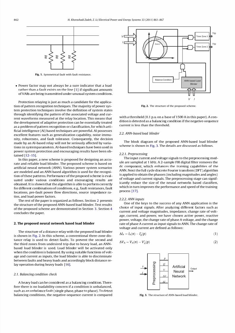
2. The proposed neural network based load blinder
The structure of a distance relay with the proposed load blinder
is shown in Fig. 2. In this scheme, a conventional three-zone dis-
tance relay is used to detect faults. To prevent the second and
the third zones from undesired trip due to heavy load, an ANN-
based load blinder is used. Load blinder will be activated only
when the condition is balanced. By using suitable functions of volt-
age and current as inputs, the load blinder is able to discriminate
between faults and heavy loads and accordingly block distance re-
lay operation during heavy loads [16].
2.1. Balancing condition check
A heavy load can be considered as a balancing condition. There-
fore there is no loadability concern if a condition is unbalanced,
such as an unbalance fault (single phase, phase to phase). To detectbalancing conditions, the negative-sequence current is compared
with a threshold (0.1 p.u. on a base of 1500 A in this paper). A con-dition is detected as a balancing condition if the negative-sequence
current is less than the threshold.
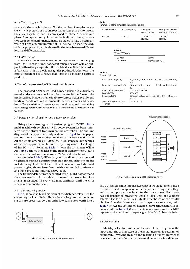
2.2. ANN-based load blinder
The block diagram of the proposed ANN-based load blinder
scheme is shown in Fig. 3. The details are discussed as follows.
2.2.1. Preprocessing
The input current and voltage signals to the preprocessing mod-
ule are sampled at 1 kHz. A 2-sample FIR digital filter removes the
dc component, which enhances the training capabilities of the
ANN. Next the full cycle discrete Fourier transform (DFT) algorithm
is applied to obtain the phasors (including magnitudes and angles)of voltage and current signals. The preprocessing stage can signif-
icantly reduce the size of the neural networks based classifiers,
which in turn improves the performance and speed of the training
process [17].
2.2.2. ANN inputs
One of the keys to the success of any ANN application is the
choice of input signals. After analyzing different factors such as
current and voltage magnitudes, impedance, change rate of volt-
age, current, and power, we have chosen active power, reactive
power, voltage, the change rate of phase A voltage, and the change
rate of phase A current as input signals to ANN. The change rate of
voltage and current are defined as follows:
DI A ¼ I AðnÞ I Að pÞ ð1ÞDV A ¼ V AðnÞ V Að pÞ ð2Þ
Fig. 1. Symmetrical fault with fault resistance.
ANN based Load
Blinder
Zone 3
Timer Zone 3V
I
V I
Balance Condition
Trip
Zone 2
Timer Zone 2
Trip
Fig. 2. The structure of the proposed scheme.
Artificial
Neural
Network
Output
V ∆
I ∆
V
Q
P
V
I
P r e p r o c e s s i n g
Fig. 3. The structure of ANN-based load blinder.
862 H. Khorashadi Zadeh, Z. Li / Electrical Power and Energy Systems 33 (2011) 861–867
8/9/2019 Adaptive load blinder for distance protection.pdf
http://slidepdf.com/reader/full/adaptive-load-blinder-for-distance-protectionpdf 3/7
n ¼ kN þ p 0 p < N
where n is the sample index and N is the number of samples per cy-
cle; I A and V A correspond to phase A current and phase A voltage at
the current cycle; I A and V A correspond to phase A current and
phase A voltage at one cycle before the fault occurrence, respec-
tively. For better performance, inputs are scaled to have a maximum
value of 1 and a minimum value of
1. As shall be seen, the ANN
with the proposed inputs is able to discriminate between differentloads and different faults.
2.2.3. ANN output
The ANN has one node in the output layer with output ranging
from 0 to 1. For the purpose of classification, any case with an out-
put less than the pre-specified threshold value of 0.5 is classified as
a fault case, thus no blocking signal is produced. Otherwise, the
case is recognized as a heavy-load case and a blocking signal is
produced.
3. Test of the proposed ANN-based load blinder
The proposed ANN-based load blinder scheme is extensively
tested under various conditions. For the studies performed, theproposed load blinder scheme is able to correctly classify different
kinds of conditions and discriminate between faults and heavy
loads. The simulation of power system conditions, and the training
and testing of the ANN-based load blinder scheme are discussed as
follows.
3.1. Power system simulation and pattern generation
Using an electro-magnetic transient program EMTDC [18], a
multi-machine three-phase 345-kV power system has been simu-
lated for the study of transmission line protection. The one-line
diagram of the system in study is shown in Fig. 4. In this paper,
we consider a distance relay installed on the bus A end of line
AB, the length of which is 150 miles. This distance relay operatesas the backup protection for line BC by using zone 3. The length
of line BC is also 150 miles. Table 1 shows the parameters of line
AB. Table 2 shows the ratios of the current transformer (CT) and
the capacitive voltage transformer (CVT) installed at bus A.
As shown in Table 3, different system conditions are simulated
to generate training patterns for the load blinder. These conditions
include heavy loads, faults at different locations with different
power angles, three-phase faults with various fault resistance,
and three-phase faults during heavy loads.
The training data sets are generated using EMTDC software and
then converted to a format that can be used by the training algo-
rithms in MATLAB. The ANN training continues until the error
reaches an acceptable level.
3.1.1. Distance relay model
Fig. 5 shows the block diagram of the distance relay used for
evaluating the load blinder. Three-phase voltage and current input
signals are processed by 2nd-order low-pass Butterworth filters
and a 2-sample Finite Impulse Response (FIR) digital filter is used
to remove the dc component. After the preprocessing, the voltageand current phasors are input to the three zones. Each zone
has six impedance measuring units, a logic unit, and a phase
selector. The logic unit issues suitable order based on the results
obtained from the phase selection and impedance measuring units.
Table 4 shows the settings of distance relay’s three zones at sec-
ondary side. In Table 4, Zr represents reach impedance and MTA
represents the maximum torque angle of the MHO characteristics.
3.2. ANN training
Multilayer feedforward networks were chosen to process the
input data. The architecture of the neural network is determined
empirically, involving training and testing a different number of layers and neurons. To choose the neural network, a few different
S R
Distance Relay
P + j Q
A B C
CT
CVT
Fig. 4. Model of the simulated power system.
Table 1
Parameters of the simulated transmission lines.
R1 (ohm/mile) X 1 (ohm/mile) Emergency
power rating
Emergency power
rating for 15 min
0.01650 0.5133 717 MVA 956 MVA
(1200 A) (1600 A)
Table 2
CT and CVT ratio.
CT ratio 1500:5
CVT ratio 345000:110 ffiffiffi
3p
Table 3
Training patterns.
Fault location (mile) 10, 30, 60, 80, 120, 140, 170, 200, 225, 250, 275,
300
Fault inception angle () Different values between (0–360) with a step of
45
Fault resistance (ohm) 0, 4, 8, 12, 16, 20
Load (MVA) 100–950Load angle () Different values between (60 to 60) with a step
of 15
Source impedance ratio
(SIR)
0.5, 5, 10, 15
Zone 1
Zone 2
Zone 3 P r e - p r o c e s s i n g
ia
ib
ic
va
vb
vc
a-g
Measuringelements
b-g
c-g
a-b
b-c
c-a
logic
Distance relay model
Structure of each zone
Fig. 5. The block diagram of the distance relay.
H. Khorashadi Zadeh, Z. Li/ Electrical Power and Energy Systems 33 (2011) 861–867 863
8/9/2019 Adaptive load blinder for distance protection.pdf
http://slidepdf.com/reader/full/adaptive-load-blinder-for-distance-protectionpdf 4/7
network structures with appropriate number of neurons in their
hidden layers were considered. Different networks with one and
two hidden layers were considered and trained. It was found that
the networks with reasonable number of neurons in their only hid-
den layers can not cover some of the extreme cases. On the other
hand, networks with two hidden layers provided better results
without having to have high number of neurons in their only hid-
den layers. The number of neurons for the two hidden layers is 10
and 5, respectively. As explained in Sections 2.2.2 and 2.2.3, there
are 5 neurons in the input layer and 1 neuron in the output layer. A
tan-sigmoid function is used as the activation function for the hid-
den layer. A sigmoid function is used for the output layer.
Various networks with different number of neurons in their
hidden layer were trained with both conventional Back-Propaga-tion (BP) and Marquardt–Levenberg (ML) algorithms [17,19].
While BP is a steepest descent algorithm, ML algorithm is an
approximation to the Newton’s method. The ML algorithm is a
nonlinear least square algorithm applied to learning of the multi-
layer perceptrons. The Marquardt–Levnberg update rule is:
DW ¼ ð J T J þ lI Þ1 J T e ð3Þwhere J is the Jacobian matrix of derivatives of each error to each
weight, l is a scalar and e is an error vector. If the scalar l is very
large, the above expression approximates gradient descent, while
if it is small then it becomes the Gauss–Newton method.
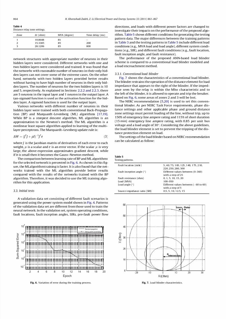
The comparison between learning rate of BP and ML algorithms
for the selected network is presented in Fig. 6. As shown in this fig-
ure, the MLalgorithmtraining is faster. It is also found that the net-works trained with the ML algorithm provide better results
compared with the results of the networks trained with the BP
algorithm. Therefore, it was decided to use the ML training algo-
rithm for this application.
3.3. Initial tests
A validation data set consisting of different fault scenarios is
generated using the power system model shown in Fig. 4. Patterns
of the validation data set are different from those used to train the
neural network. In the validation set, system operating conditions,
fault locations, fault inception angles, SIRs, pre-fault power flow
directions, and loads with different power factors are changed to
investigate their impacts on the performance of the proposed algo-
rithm. Table 5 shows different conditions for generating the testing
pattern data. The major differences between the training patterns
in Table 3 and the testing patterns in Table 5 include different load
conditions (e.g., MVA load and load angle), different system condi-
tions (e.g., SIR), and different fault conditions (e.g., fault location,
fault inception angle, and fault resistance).
The performance of the proposed ANN-based load blinder
scheme is compared to a conventional load blinder modeled and
a load encroachment method.
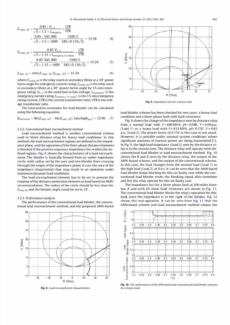
3.3.1. Conventional load blinder
Fig. 7 shows the characteristics of a conventional load blinder.
The blinder restrains the operation of the distance element for load
impedance that appears to the right of the blinder. If the imped-
ance seen by the relay is within the Mho characteristic and to
the left of the blinder, it is allowed to operate and trip the breaker.
Based on Fig. 6, some areas of zones 2 and 3 will be lost.
The NERC recommendation [5,20] is used to set this conven-
tional blinder. As per NERC Task Force requirements, phase dis-
tance settings and other applicable phase and ground distance
zone settings must permit loading of the line, without trip, up to
150% of emergency line ampere rating and 115% of short duration
(15 min) emergency line ampere rating, with 0.85 per unit bus
voltage and a load angle of 30. Considering the above guidelines,
the load blinder element is set to prevent the tripping of the dis-
tance protection element on load.
The settings of the load blinder based on NERC recommendation
can be calculated as follow:
Table 4
Distance relay zone settings.
Zone Zr (ohm) MTA (degree) Time delay (ms)
1 10.8648 85 –
2 15.3385 85 200
3 28.1206 85 800
2 4 6 8 10 12 14 16 18 20
10-1
100
101
102
103
104
Epoch
S u m - S q u a r e d E r r o r
Backpropagation
Marquardt-Levenberg
Fig. 6. Variation of error during the training process.
Table 5
Testing patterns.
Fault location (mile) 5, 40, 75, 100, 125, 140, 175, 210,
220, 250, 280, 300
Fault inception angle () Dif ferent values between (0–360)
with a step of 25
Fault resistance (ohm) 0, 1, 5, 10, 15, 20
Load (MVA) 100–950
Load angle () Different values between (60 to 60)
with a step of 5
Source impedance ratio (SIR) 0.5, 5, 10, 12.5, 15
Fig. 7. Load blinder characteristics.
864 H. Khorashadi Zadeh, Z. Li / Electrical Power and Energy Systems 33 (2011) 861–867
8/9/2019 Adaptive load blinder for distance protection.pdf
http://slidepdf.com/reader/full/adaptive-load-blinder-for-distance-protectionpdf 5/7
8/9/2019 Adaptive load blinder for distance protection.pdf
http://slidepdf.com/reader/full/adaptive-load-blinder-for-distance-protectionpdf 6/7
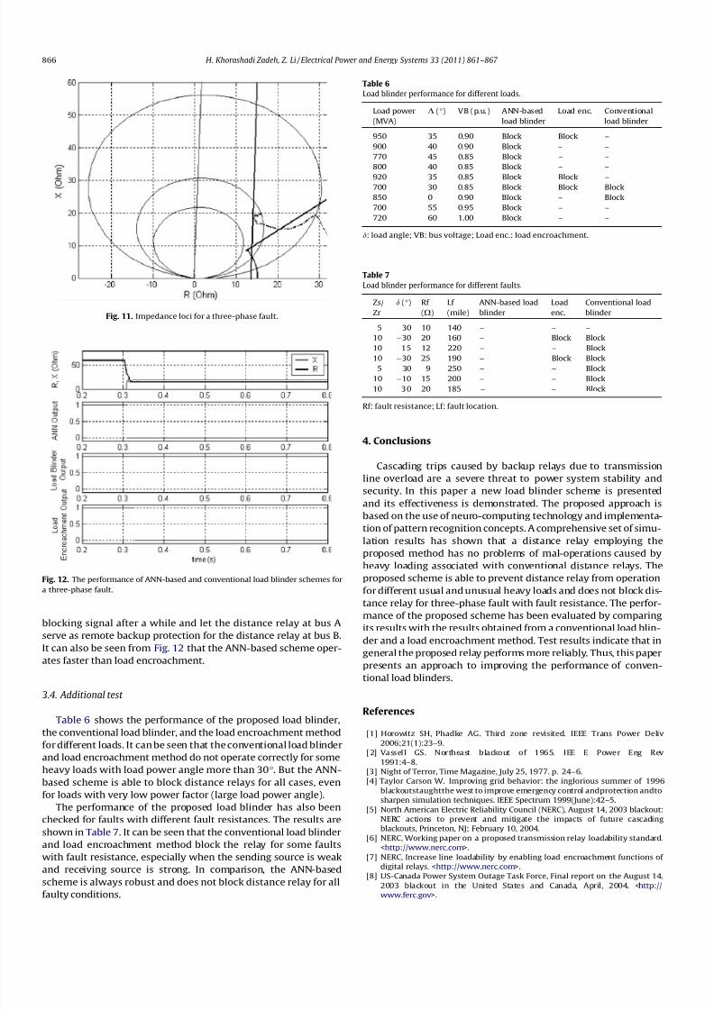
blocking signal after a while and let the distance relay at bus A
serve as remote backup protection for the distance relay at bus B.
It can also be seen from Fig. 12 that the ANN-based scheme oper-
ates faster than load encroachment.
3.4. Additional test
Table 6 shows the performance of the proposed load blinder,
the conventional load blinder, and the load encroachment method
for different loads. It can be seen that the conventional load blinder
and load encroachment method do not operate correctly for some
heavy loads with load power angle more than 30. But the ANN-
based scheme is able to block distance relays for all cases, even
for loads with very low power factor (large load power angle).
The performance of the proposed load blinder has also been
checked for faults with different fault resistances. The results are
shown in Table 7. It can be seen that the conventional load blinder
and load encroachment method block the relay for some faults
with fault resistance, especially when the sending source is weak
and receiving source is strong. In comparison, the ANN-based
scheme is always robust and does not block distance relay for allfaulty conditions.
4. Conclusions
Cascading trips caused by backup relays due to transmission
line overload are a severe threat to power system stability and
security. In this paper a new load blinder scheme is presented
and its effectiveness is demonstrated. The proposed approach is
based on the use of neuro-computing technology and implementa-
tion of pattern recognition concepts. A comprehensive set of simu-lation results has shown that a distance relay employing the
proposed method has no problems of mal-operations caused by
heavy loading associated with conventional distance relays. The
proposed scheme is able to prevent distance relay from operation
for different usual and unusual heavy loads and does not block dis-
tance relay for three-phase fault with fault resistance. The perfor-
mance of the proposed scheme has been evaluated by comparing
its results with the results obtained from a conventional load blin-
der and a load encroachment method. Test results indicate that in
general the proposed relay performs more reliably. Thus, this paper
presents an approach to improving the performance of conven-
tional load blinders.
References
[1] Horowitz SH, Phadke AG. Third zone revisited. IEEE Trans Power Deliv
2006;21(1):23–9.
[2] Vassell GS. Northeast blackout of 1965. IEE E Power Eng Rev
1991:4–8.
[3] Night of Terror, Time Magazine, July 25, 1977. p. 24–6.
[4] Taylor Carson W. Improving grid behavior: the inglorious summer of 1996
blackoutstaughtthe west to improve emergency control andprotection andto
sharpen simulation techniques. IEEE Spectrum 1999(June):42–5.
[5] North American Electric Reliability Council (NERC), August 14, 2003 blackout:
NERC actions to prevent and mitigate the impacts of future cascading
blackouts, Princeton, NJ; February 10, 2004.
[6] NERC, Working paper on a proposed transmission relay loadability standard.
<http://www.nerc.com>.
[7] NERC, Increase line loadability by enabling load encroachment functions of
digital relays. <http://www.nerc.com>.
[8] US-Canada Power System Outage Task Force, Final report on the August 14,
2003 blackout in the United States and Canada, April, 2004. <http://www.ferc.gov>.
Fig. 12. The performance of ANN-based and conventional load blinder schemes for
a three-phase fault.
Fig. 11. Impedance loci for a three-phase fault.
Table 6
Load blinder performance for different loads.
Load power
(MVA)
D () VB (p.u.) ANN-based
load blinder
Load enc. Conventional
load blinder
950 35 0.90 Block Block –
900 40 0.90 Block – –
770 45 0.85 Block – –
800 40 0.85 Block – –
920 35 0.85 Block Block –700 30 0.85 Block Block Block
850 0 0.90 Block – Block
700 55 0.95 Block – –
720 60 1.00 Block – –
d: load angle; VB: bus voltage; Load enc.: load encroachment.
Table 7
Load blinder performance for different faults.
Zs/
Zr
d () Rf
(X)
Lf
(mile)
ANN-based load
blinder
Load
enc.
Conventional load
blinder
5 30 10 140 – – –
10 30 20 160 – Block Block
10 15 12 220 – – Block
10 30 25 190 – Block Block
5 30 9 250 – – Block
10 10 15 200 – – Block
10 30 20 185 – – Block
Rf: fault resistance; Lf: fault location.
866 H. Khorashadi Zadeh, Z. Li / Electrical Power and Energy Systems 33 (2011) 861–867

8/9/2019 Adaptive load blinder for distance protection.pdf
http://slidepdf.com/reader/full/adaptive-load-blinder-for-distance-protectionpdf 7/7
[9] Network Protection and Automation Guide, ISBN-2-95 18589-0-6, ALSTOM
(AREVA); 2002.
[10] Apostolov AP, Tholomier D, Richards SH. Distance protection and dynamic
loading of transmission lines. IEEE Power Eng Soc General Meet 2004.
[11] Tziouvaras D. Relay performance during major system disturbances. <http://
www.selinc.com/techpprs/6244_RelayPerformance_DT_20060914.pdf’>.
[12] Khorashadi-Zadeh H, Li Z. A novel power swing blocking scheme using
adaptive neuro-fuzzy inference system. Electric Power Syst Res (Elsevier)
2008;78(7):1138–114638.
[13] Sanaye-Pasand M, Khorashadi-Zadeh H. An extended ABB-based high speed
accurate distance protection algorithm. Int J Electrical Power Energy Syst(Elsevier) 2006;28:387–95.
[14] Bhowmik PS, Purkait P, Bhattacharya K. A novel wavelet transform aided
neural network based transmission line fault analysis method. Int J Electrical
Power Energy Syst 2009;31(5):213–9.
[15] Samantaray SR, Dash PK, Upadhyay SK. Adaptive Kalman filter and neural
network based high impedance fault detection in power distribution
networks. Int J Electrical Power Energy Syst 2009;31(4):167–72.
[16] Khorashadi-Zadeh H, Li Z. Artificial neural network based load blinder for
distance protection. IEEE Power Eng Soc General Meet 2008.
[17] Hagan M, Menhaj M. Training feedforward networks with the Marquardt
algorithm. IEEE Trans Neural Networks 1994;5(6):989–93.
[18] PSCAD/EMTDC user’s manual, Manitoba HVDC Research Center, Winnipeg,
Manitoba, Canada.
[19] Haykin S. Neural networks. New York: IEEE Press; 1994.
[20] NERC, Relay loadability exceptions, determination and application of practicalrelaying loadability ratings; September 2004.
H. Khorashadi Zadeh, Z. Li/ Electrical Power and Energy Systems 33 (2011) 861–867 867