Embed Size (px)
Citation preview
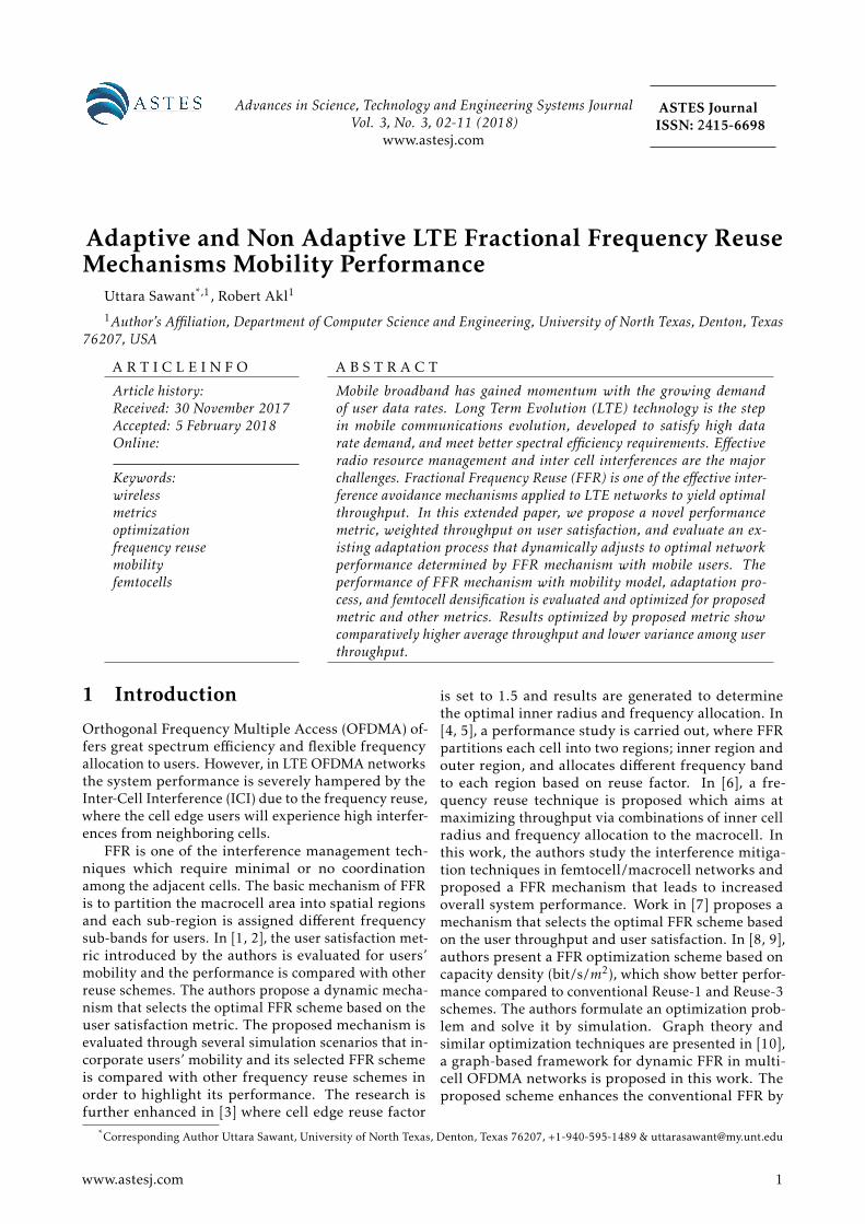
Advances in Science, Technology and Engineering Systems JournalVol. 3, No. 3, 02-11 (2018)
www.astesj.com
ASTES JournalISSN: 2415-6698
Adaptive and Non Adaptive LTE Fractional Frequency ReuseMechanisms Mobility Performance
Uttara Sawant*,1, Robert Akl1
1Author’s Affiliation, Department of Computer Science and Engineering, University of North Texas, Denton, Texas76207, USA
A R T I C L E I N F O A B S T R A C T
Article history:Received: 30 November 2017Accepted: 5 February 2018Online:
Keywords:wirelessmetricsoptimizationfrequency reusemobilityfemtocells
Mobile broadband has gained momentum with the growing demandof user data rates. Long Term Evolution (LTE) technology is the stepin mobile communications evolution, developed to satisfy high datarate demand, and meet better spectral efficiency requirements. Effectiveradio resource management and inter cell interferences are the majorchallenges. Fractional Frequency Reuse (FFR) is one of the effective inter-ference avoidance mechanisms applied to LTE networks to yield optimalthroughput. In this extended paper, we propose a novel performancemetric, weighted throughput on user satisfaction, and evaluate an ex-isting adaptation process that dynamically adjusts to optimal networkperformance determined by FFR mechanism with mobile users. Theperformance of FFR mechanism with mobility model, adaptation pro-cess, and femtocell densification is evaluated and optimized for proposedmetric and other metrics. Results optimized by proposed metric showcomparatively higher average throughput and lower variance among userthroughput.
1 Introduction
Orthogonal Frequency Multiple Access (OFDMA) of-fers great spectrum efficiency and flexible frequencyallocation to users. However, in LTE OFDMA networksthe system performance is severely hampered by theInter-Cell Interference (ICI) due to the frequency reuse,where the cell edge users will experience high interfer-ences from neighboring cells.
FFR is one of the interference management tech-niques which require minimal or no coordinationamong the adjacent cells. The basic mechanism of FFRis to partition the macrocell area into spatial regionsand each sub-region is assigned different frequencysub-bands for users. In [1, 2], the user satisfaction met-ric introduced by the authors is evaluated for users’mobility and the performance is compared with otherreuse schemes. The authors propose a dynamic mecha-nism that selects the optimal FFR scheme based on theuser satisfaction metric. The proposed mechanism isevaluated through several simulation scenarios that in-corporate users’ mobility and its selected FFR schemeis compared with other frequency reuse schemes inorder to highlight its performance. The research isfurther enhanced in [3] where cell edge reuse factor
is set to 1.5 and results are generated to determinethe optimal inner radius and frequency allocation. In[4, 5], a performance study is carried out, where FFRpartitions each cell into two regions; inner region andouter region, and allocates different frequency bandto each region based on reuse factor. In [6], a fre-quency reuse technique is proposed which aims atmaximizing throughput via combinations of inner cellradius and frequency allocation to the macrocell. Inthis work, the authors study the interference mitiga-tion techniques in femtocell/macrocell networks andproposed a FFR mechanism that leads to increasedoverall system performance. Work in [7] proposes amechanism that selects the optimal FFR scheme basedon the user throughput and user satisfaction. In [8, 9],authors present a FFR optimization scheme based oncapacity density (bit/s/m2), which show better perfor-mance compared to conventional Reuse-1 and Reuse-3schemes. The authors formulate an optimization prob-lem and solve it by simulation. Graph theory andsimilar optimization techniques are presented in [10],a graph-based framework for dynamic FFR in multi-cell OFDMA networks is proposed in this work. Theproposed scheme enhances the conventional FFR by
*Corresponding Author Uttara Sawant, University of North Texas, Denton, Texas 76207, +1-940-595-1489 & [email protected]
www.astesj.com 1
U. Sawant et al. / Advances in Science, Technology and Engineering Systems Journal Vol. 3, No. 3, 02-11 (2018)
enabling adaptive spectral sharing per cell load con-ditions. Such adaptation has significant benefits ina practical environment, where traffic load in differ-ent cells may be asymmetric and time-varying. Workin [11, 12] provides analysis of the inter cell interfer-ence coordination problem in multi-cell OFDMA sys-tems. In order to reduce the interference without los-ing much frequency resources in each cell, cell usersare partitioned into two classes, interior and exteriorusers. Results determine the optimal configuration ofthe interior and exterior regions’ dimensions as well asthe optimal frequency reuse factor.
Authors in [13] use two-stage heuristic approachto find optimal frequency partitioning. The authorsintend to propose the FFR scheme by introducing theconcept of normalized Spectral Efficiency (nSE). Withthe optimal Frequency Reuse Factor (FRF), the FFRscheme can maximize the system SE with throughputimprovement of cell-edge users. To solve the problem,they divide it into two sub-problems. However, thisscheme is asymptotically optimal with the assumptionof the uniform distributions of signal and interferencein sectors. The simulation results demonstrate thegain of the system SE is about 3% by proposed FFRscheme. The goal in work in [14] is to improve the celledge throughput as well as the average cell throughput,compared to a network with frequency reuse factor 1.The cell capacity under those reuse schemes is esti-mated and compared. To attain both high spectralefficiency and good coverage within sectors/beams, ascheme based on coordinated scheduling between sec-tors of the same site, and the employment of frequencyreuse factor above 1 only in outer parts of the sector, isproposed and evaluated. The resulting sector through-put increases with the number of active users. Whenterminals have one antenna and channels are Rayleighfading, it results in a sector payload capacity between1.2 (one user) and 2.1 bits/s/Hz/sector (for 30 users)in an interference-limited environment [15]. In [16],the authors review some of the recent advances in ICIresearch and discuss the assumptions, advantages, andlimitations of the proposed mechanisms. They pro-pose a scheduling algorithm to schedule users basedon channel quality and quality of service (QoS) met-rics.
Authors in [17] investigate an OFDMA radio re-source control (RRC) scheme, where RRC control isexercised at both RNC and base stations. In [18], theauthors present an analytical solution to carry out per-formance study of various frequency reuse schemes inan OFDMA based cellular network. Results of perfor-mance study show that results obtained through ana-lytical method are in conformity with those obtainedthrough simulations. In [19], the authors analyze theFFR scheme and propose a dynamic FFR mechanismthat selects the optimal frequency allocation based onthe cell total throughput and user satisfaction.
Extensive work is done to optimize network per-formance of FFR mechanism [20]. FFR and exploita-tion of the channel state information at the transmitter(CSIT) are effective approaches to improving the spec-
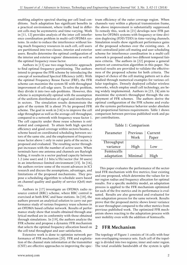
trum efficiency of the outer coverage region. Whenchannels vary within a physical transmission frame,the above improvement is substantially suppressed.To remedy this, work in [21] develops new FFR pat-terns for OFDMA systems with frequency or time divi-sion duplexing (FDD/TDD) in time-varying channels.Simulation results show significant performance gainsof the proposed schemes over the existing ones. Asemi-centralized joint cell muting and user schedulingscheme for interference coordination in a multi-cellnetwork is proposed under two different temporal fair-ness criteria. The authors in [22] propose a generalpattern set construction algorithm in this paper. Nu-merical results are provided to validate the effective-ness of the proposed scheme for both criteria. Theimpact of choice of the cell muting pattern set is alsostudied through numerical examples for various cel-lular topologies. Densely deployed cellular wirelessnetworks, which employ small cell technology, are be-ing widely implemented. Authors in [23, 24] aim tomaximize the system’s throughput through the em-ployment of FFR schemes. The authors derive theoptimal configuration of the FFR scheme and evalu-ate the systems performance behavior under absoluteand proportional fairness requirements. Table 1 showscomparison between previous published work and pa-per contributions.
Table 1: Comparison
Parameter Previous CurrentWork Paper
Throughputvariance High Low
Femtocellsadaptation Minimal High
This paper evaluates the performance of the sector-ized FFR mechanism with five metrics; four existingand one proposed, which determine the values for in-ner region radius and frequency allocation for optimalresults. For a specific mobility model, an adaptationprocess is applied to the FFR mechanism optimizedfor each of the five metrics and its performance is eval-uated. Results are also generated and evaluated fornon-adaptation process for the same network. Resultsprove that the proposed metric shows lower variancein user throughput compared to the other metrics fromprevious published work. The optimized FFR mech-anism shows reacting to the adaptation process withuser mobility even with the addition of femtocells.
2 FFR Mechanism
The topology of Figure 1 consists of 16 cells with fournon-overlapping resource sets. Each cell of the topol-ogy is divided into two regions; inner and outer region.The total available bandwidth of the system is split
www.astesj.com 2
U. Sawant et al. / Advances in Science, Technology and Engineering Systems Journal Vol. 3, No. 3, 02-11 (2018)
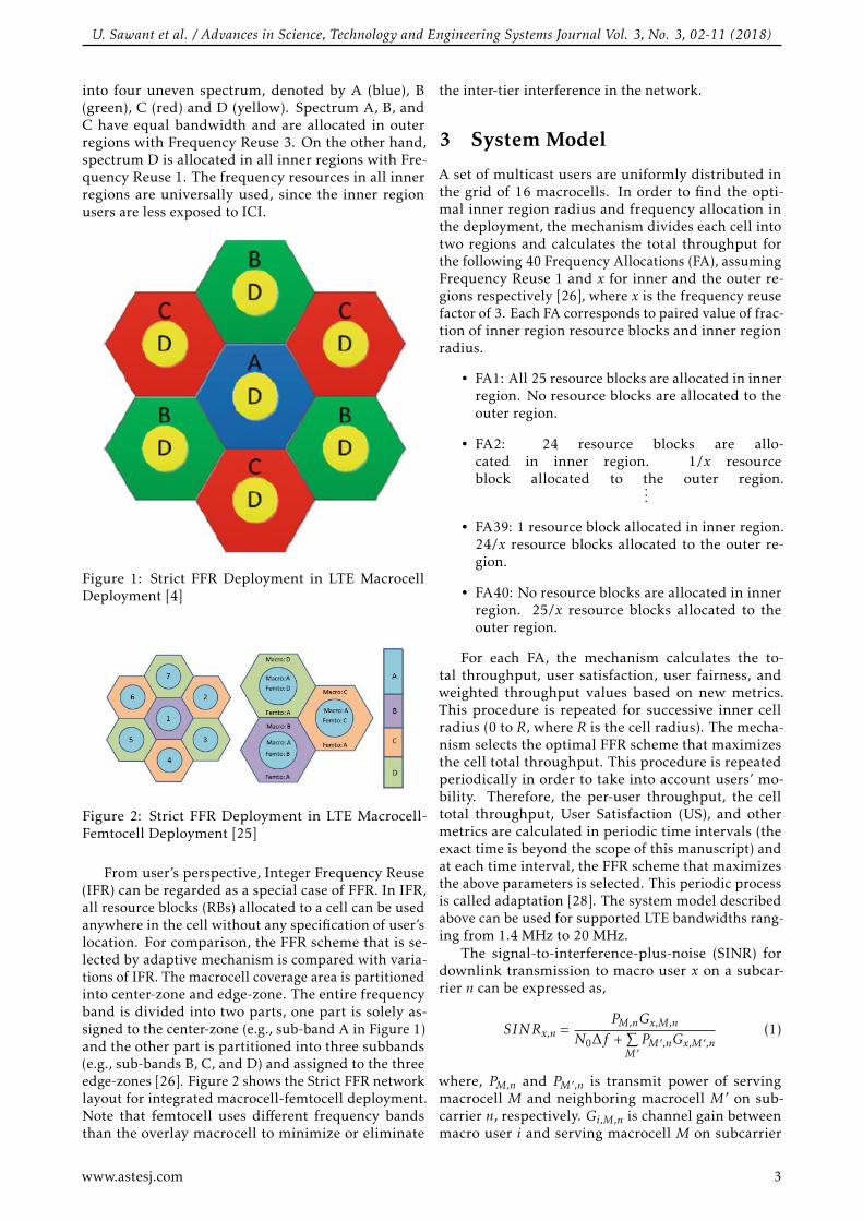
into four uneven spectrum, denoted by A (blue), B(green), C (red) and D (yellow). Spectrum A, B, andC have equal bandwidth and are allocated in outerregions with Frequency Reuse 3. On the other hand,spectrum D is allocated in all inner regions with Fre-quency Reuse 1. The frequency resources in all innerregions are universally used, since the inner regionusers are less exposed to ICI.
Figure 1: Strict FFR Deployment in LTE MacrocellDeployment [4]
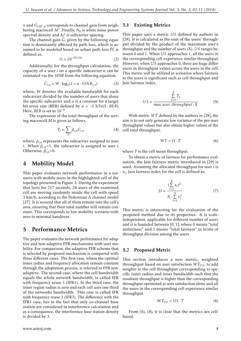
Figure 2: Strict FFR Deployment in LTE Macrocell-Femtocell Deployment [25]
From user’s perspective, Integer Frequency Reuse(IFR) can be regarded as a special case of FFR. In IFR,all resource blocks (RBs) allocated to a cell can be usedanywhere in the cell without any specification of user’slocation. For comparison, the FFR scheme that is se-lected by adaptive mechanism is compared with varia-tions of IFR. The macrocell coverage area is partitionedinto center-zone and edge-zone. The entire frequencyband is divided into two parts, one part is solely as-signed to the center-zone (e.g., sub-band A in Figure 1)and the other part is partitioned into three subbands(e.g., sub-bands B, C, and D) and assigned to the threeedge-zones [26]. Figure 2 shows the Strict FFR networklayout for integrated macrocell-femtocell deployment.Note that femtocell uses different frequency bandsthan the overlay macrocell to minimize or eliminate
the inter-tier interference in the network.
3 System Model
A set of multicast users are uniformly distributed inthe grid of 16 macrocells. In order to find the opti-mal inner region radius and frequency allocation inthe deployment, the mechanism divides each cell intotwo regions and calculates the total throughput forthe following 40 Frequency Allocations (FA), assumingFrequency Reuse 1 and x for inner and the outer re-gions respectively [26], where x is the frequency reusefactor of 3. Each FA corresponds to paired value of frac-tion of inner region resource blocks and inner regionradius.
• FA1: All 25 resource blocks are allocated in innerregion. No resource blocks are allocated to theouter region.
• FA2: 24 resource blocks are allo-cated in inner region. 1/x resourceblock allocated to the outer region....
• FA39: 1 resource block allocated in inner region.24/x resource blocks allocated to the outer re-gion.
• FA40: No resource blocks are allocated in innerregion. 25/x resource blocks allocated to theouter region.
For each FA, the mechanism calculates the to-tal throughput, user satisfaction, user fairness, andweighted throughput values based on new metrics.This procedure is repeated for successive inner cellradius (0 to R, where R is the cell radius). The mecha-nism selects the optimal FFR scheme that maximizesthe cell total throughput. This procedure is repeatedperiodically in order to take into account users’ mo-bility. Therefore, the per-user throughput, the celltotal throughput, User Satisfaction (US), and othermetrics are calculated in periodic time intervals (theexact time is beyond the scope of this manuscript) andat each time interval, the FFR scheme that maximizesthe above parameters is selected. This periodic processis called adaptation [28]. The system model describedabove can be used for supported LTE bandwidths rang-ing from 1.4 MHz to 20 MHz.
The signal-to-interference-plus-noise (SINR) fordownlink transmission to macro user x on a subcar-rier n can be expressed as,
SINRx,n =PM,nGx,M,n
N0∆f +∑M ′PM ′ ,nGx,M ′ ,n
(1)
where, PM,n and PM ′ ,n is transmit power of servingmacrocell M and neighboring macrocell M ′ on sub-carrier n, respectively. Gi,M,n is channel gain betweenmacro user i and serving macrocell M on subcarrier
www.astesj.com 3
U. Sawant et al. / Advances in Science, Technology and Engineering Systems Journal Vol. 3, No. 3, 02-11 (2018)
n and Gi,M ′ ,n corresponds to channel gain from neigh-boring macrocell M ′ . Finally, N0 is white noise powerspectral density and ∆f is subcarrier spacing.
The channel gain G, given by the following equa-tion is dominantly affected by path loss, which is as-sumed to be modeled based on urban path-loss PL isdefined as,
G = 10−P L/10 (2)
Additionally, for the throughput calculation, thecapacity of a user i on a specific subcarrier n can beestimated via the SINR from the following equation,
Ci,n =W · log2(1 +α · SINRi,n) (3)
where, W denotes the available bandwidth for eachsubcarrier divided by the number of users that sharethe specific subcarrier and α is a constant for a targetbit error rate (BER) defined by α = −1.5/ln(5 · BER).Here, BER is set to 10−6.
The expression of the total throughput of the serv-ing macrocell M is given as follows,
Ti =∑n
βi,nCi,n (4)
where, βi,n represents the subcarrier assigned to useri. When βi,n=1, the subcarrier is assigned to user i.Otherwise, βi,n=0.
4 Mobility Model
This paper evaluates network performance in a sce-nario with mobile users in the highlighted cell of thetopology presented in Figure 3. During the experimentthat lasts for 217 seconds, 24 users of the examinedcell are moving randomly inside the cell with speed3 km/h, according to the Pedestrian A channel model[27]. It is assured that all of them remain into the cell’sarea, ensuring that their total number will remain con-stant. This corresponds to low mobility scenario withzero to minimal handover.
5 Performance Metrics
The paper evaluates the network performance for adap-tive and non-adaptive FFR mechanisms with user mo-bility. For comparison, the adaptive FFR scheme thatis selected by proposed mechanism is compared withthree different cases. The first case, where the optimalinner radius and frequency allocation remain constantthrough the adaptation process, is referred to FFR non-adaptive. The second case, where the cell bandwidthequals the whole network bandwidth, is called IFRwith frequency reuse 1 (IFR1). In the third case, theinner region radius is zero and each cell uses one thirdof the networks bandwidth. This case is called IFRwith frequency reuse 3 (IFR3). The difference with theIFR1 case, lies in the fact that only co-channel basestation are considered in interference calculation andas a consequence, the interference base station densityis divided by 3.
5.1 Existing Metrics
This paper uses a metric US defined by authors in[28]. It is calculated as the sum of the users’ through-put divided by the product of the maximum user’sthroughput and the number of users (X).US ranges be-tween 0 and 1. When US approaches 1, all the users inthe corresponding cell experience similar throughput.However, when US approaches 0, there are huge differ-ences in throughput values across the users in the cell.This metric will be utilized in scenarios where fairnessto the users is significant such as cell throughput andJain fairness index.
US =
X∑x=1
Tx
max user throughput ·X(5)
With metric WT defined by the authors in [28], theaim is to not only generate low variance of the per-userthroughput values but also obtain higher values of thecell total throughput.
WT = JI · T (6)
where T is the cell mean throughput.To obtain a metric of fairness for performance eval-
uation, the Jain fairness metric introduced in [29] isused. Assuming the allocated throughput for user i isxi , Jain fairness index for the cell is defined as,
JI =(X∑i=1xi)2
X ·X∑i=1x2i
(7)
This metric is interesting for the evaluation of theproposed method due to its properties. It is scale-independent, applicable for different number of usersand it is bounded between [0, 1], where 0 means “totalunfairness” and 1 means “total fairness” in terms ofthroughput division among the users.
5.2 Proposed Metric
This section introduces a new metric, weightedthroughput based on user satisfaction WTUS , to addweights to the cell throughput corresponding to spe-cific inner radius and inner bandwidth such that theresultant throughput is higher than the correspondingthroughput optimized at user satisfaction alone and allthe users in the corresponding cell experience similarthroughput.
WTUS =US · T (8)
From (6), (8), it is clear that the metrics are cell-based.
www.astesj.com 4
U. Sawant et al. / Advances in Science, Technology and Engineering Systems Journal Vol. 3, No. 3, 02-11 (2018)
6 Performance Evaluation
6.1 Mathematical Model
The product model is applied as mathematical modelin the new metric definition and development. Pre-vious metric, weighted throughput, adds the benefitsof the individual component metrics, throughput andfairness index. Similarly, the proposed metric definedby the product model of throughput and user satisfac-tion, is expected to perform better than the individualcomponent metrics.
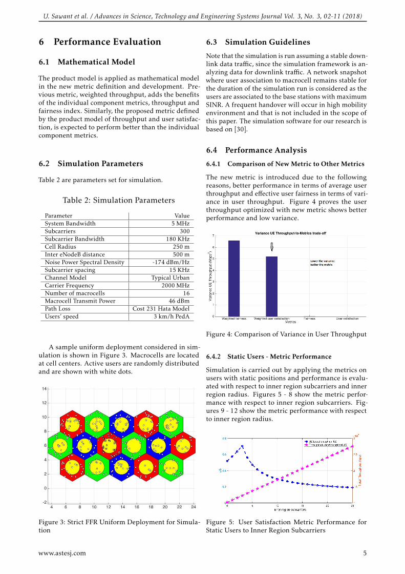
6.2 Simulation Parameters
Table 2 are parameters set for simulation.
Table 2: Simulation Parameters
Parameter ValueSystem Bandwidth 5 MHzSubcarriers 300Subcarrier Bandwidth 180 KHzCell Radius 250 mInter eNodeB distance 500 mNoise Power Spectral Density -174 dBm/HzSubcarrier spacing 15 KHzChannel Model Typical UrbanCarrier Frequency 2000 MHzNumber of macrocells 16Macrocell Transmit Power 46 dBmPath Loss Cost 231 Hata ModelUsers’ speed 3 km/h PedA
A sample uniform deployment considered in sim-ulation is shown in Figure 3. Macrocells are locatedat cell centers. Active users are randomly distributedand are shown with white dots.
Figure 3: Strict FFR Uniform Deployment for Simula-tion
6.3 Simulation Guidelines
Note that the simulation is run assuming a stable down-link data traffic, since the simulation framework is an-alyzing data for downlink traffic. A network snapshotwhere user association to macrocell remains stable forthe duration of the simulation run is considered as theusers are associated to the base stations with maximumSINR. A frequent handover will occur in high mobilityenvironment and that is not included in the scope ofthis paper. The simulation software for our research isbased on [30].
6.4 Performance Analysis
6.4.1 Comparison of New Metric to Other Metrics
The new metric is introduced due to the followingreasons, better performance in terms of average userthroughput and effective user fairness in terms of vari-ance in user throughput. Figure 4 proves the userthroughput optimized with new metric shows betterperformance and low variance.
Figure 4: Comparison of Variance in User Throughput
6.4.2 Static Users - Metric Performance
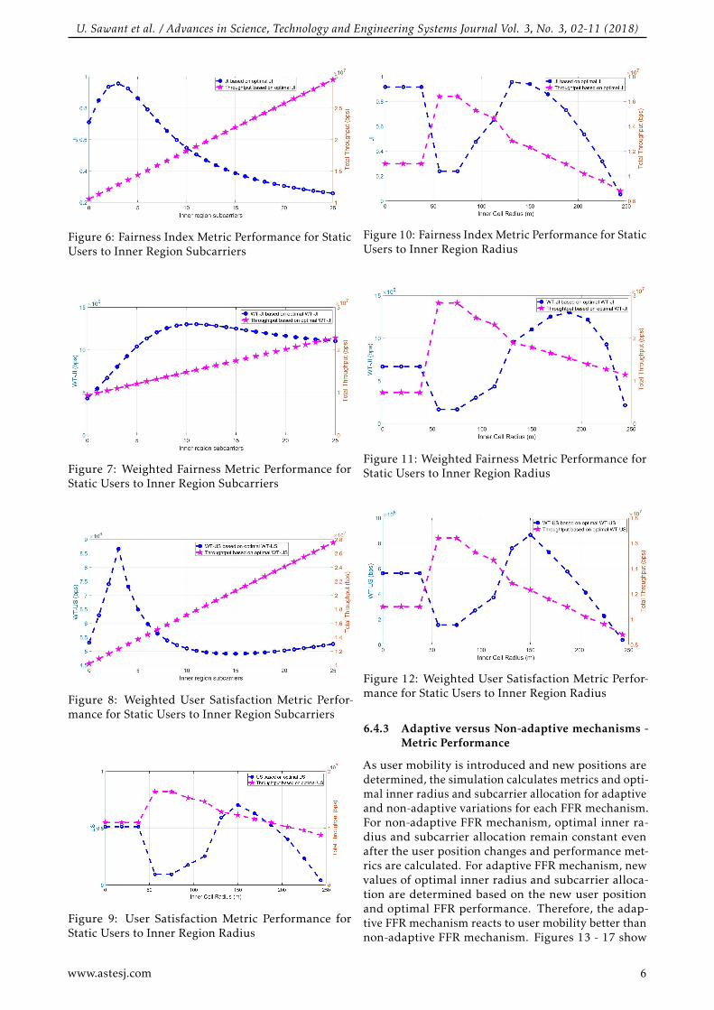
Simulation is carried out by applying the metrics onusers with static positions and performance is evalu-ated with respect to inner region subcarriers and innerregion radius. Figures 5 - 8 show the metric perfor-mance with respect to inner region subcarriers. Fig-ures 9 - 12 show the metric performance with respectto inner region radius.
Figure 5: User Satisfaction Metric Performance forStatic Users to Inner Region Subcarriers
www.astesj.com 5
U. Sawant et al. / Advances in Science, Technology and Engineering Systems Journal Vol. 3, No. 3, 02-11 (2018)
Figure 6: Fairness Index Metric Performance for StaticUsers to Inner Region Subcarriers
Figure 7: Weighted Fairness Metric Performance forStatic Users to Inner Region Subcarriers
Figure 8: Weighted User Satisfaction Metric Perfor-mance for Static Users to Inner Region Subcarriers
Figure 9: User Satisfaction Metric Performance forStatic Users to Inner Region Radius
Figure 10: Fairness Index Metric Performance for StaticUsers to Inner Region Radius
Figure 11: Weighted Fairness Metric Performance forStatic Users to Inner Region Radius
Figure 12: Weighted User Satisfaction Metric Perfor-mance for Static Users to Inner Region Radius
6.4.3 Adaptive versus Non-adaptive mechanisms -Metric Performance
As user mobility is introduced and new positions aredetermined, the simulation calculates metrics and opti-mal inner radius and subcarrier allocation for adaptiveand non-adaptive variations for each FFR mechanism.For non-adaptive FFR mechanism, optimal inner ra-dius and subcarrier allocation remain constant evenafter the user position changes and performance met-rics are calculated. For adaptive FFR mechanism, newvalues of optimal inner radius and subcarrier alloca-tion are determined based on the new user positionand optimal FFR performance. Therefore, the adap-tive FFR mechanism reacts to user mobility better thannon-adaptive FFR mechanism. Figures 13 - 17 show
www.astesj.com 6
U. Sawant et al. / Advances in Science, Technology and Engineering Systems Journal Vol. 3, No. 3, 02-11 (2018)
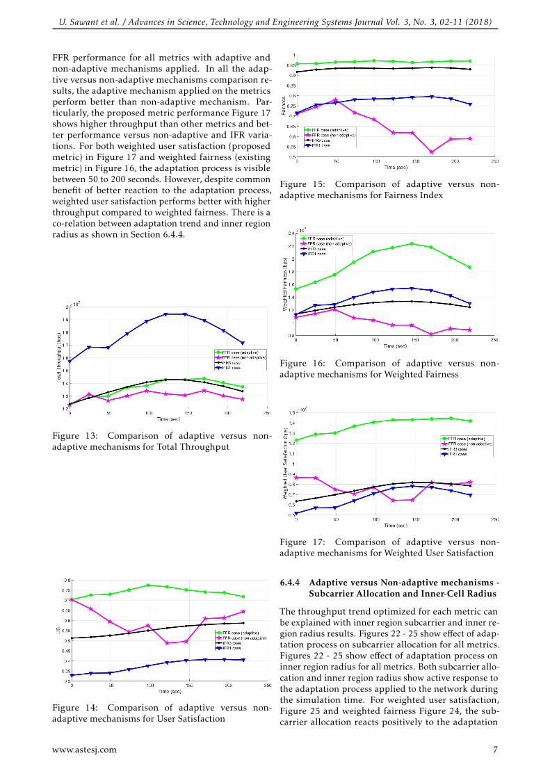
FFR performance for all metrics with adaptive andnon-adaptive mechanisms applied. In all the adap-tive versus non-adaptive mechanisms comparison re-sults, the adaptive mechanism applied on the metricsperform better than non-adaptive mechanism. Par-ticularly, the proposed metric performance Figure 17shows higher throughput than other metrics and bet-ter performance versus non-adaptive and IFR varia-tions. For both weighted user satisfaction (proposedmetric) in Figure 17 and weighted fairness (existingmetric) in Figure 16, the adaptation process is visiblebetween 50 to 200 seconds. However, despite commonbenefit of better reaction to the adaptation process,weighted user satisfaction performs better with higherthroughput compared to weighted fairness. There is aco-relation between adaptation trend and inner regionradius as shown in Section 6.4.4.
Figure 13: Comparison of adaptive versus non-adaptive mechanisms for Total Throughput
Figure 14: Comparison of adaptive versus non-adaptive mechanisms for User Satisfaction
Figure 15: Comparison of adaptive versus non-adaptive mechanisms for Fairness Index
Figure 16: Comparison of adaptive versus non-adaptive mechanisms for Weighted Fairness
Figure 17: Comparison of adaptive versus non-adaptive mechanisms for Weighted User Satisfaction
6.4.4 Adaptive versus Non-adaptive mechanisms -Subcarrier Allocation and Inner-Cell Radius
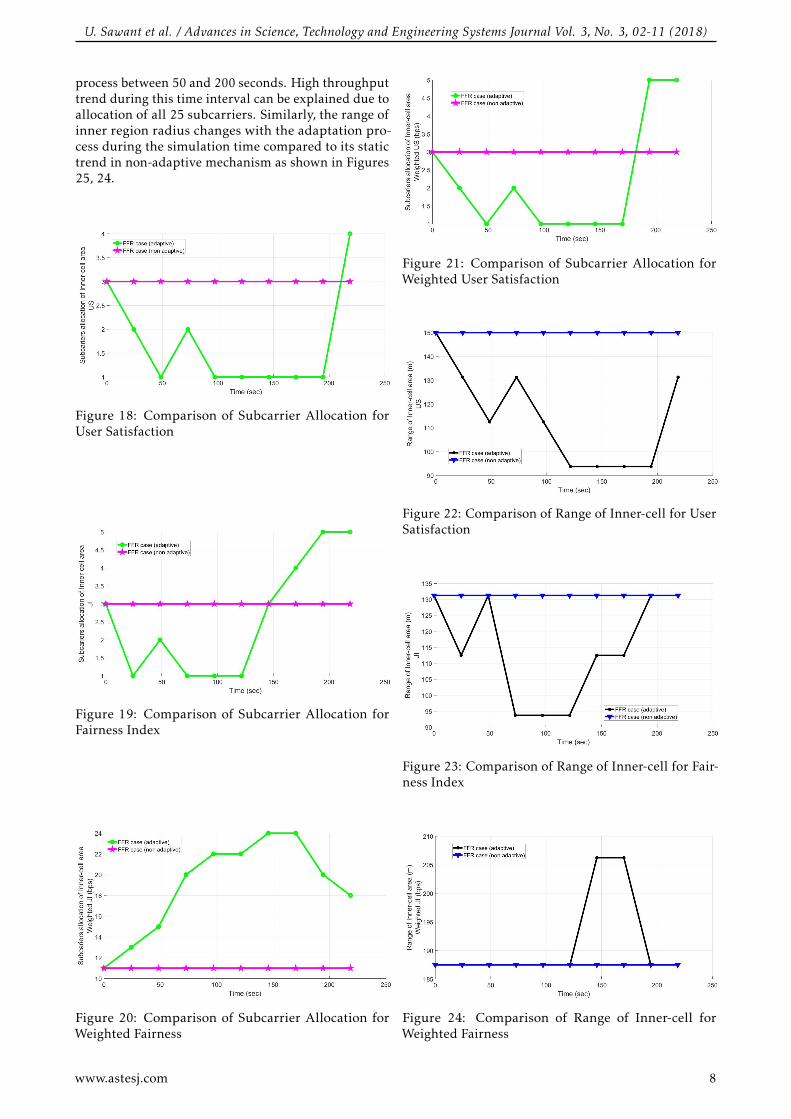
The throughput trend optimized for each metric canbe explained with inner region subcarrier and inner re-gion radius results. Figures 22 - 25 show effect of adap-tation process on subcarrier allocation for all metrics.Figures 22 - 25 show effect of adaptation process oninner region radius for all metrics. Both subcarrier allo-cation and inner region radius show active response tothe adaptation process applied to the network duringthe simulation time. For weighted user satisfaction,Figure 25 and weighted fairness Figure 24, the sub-carrier allocation reacts positively to the adaptation
www.astesj.com 7
U. Sawant et al. / Advances in Science, Technology and Engineering Systems Journal Vol. 3, No. 3, 02-11 (2018)
process between 50 and 200 seconds. High throughputtrend during this time interval can be explained due toallocation of all 25 subcarriers. Similarly, the range ofinner region radius changes with the adaptation pro-cess during the simulation time compared to its statictrend in non-adaptive mechanism as shown in Figures25, 24.
Figure 18: Comparison of Subcarrier Allocation forUser Satisfaction
Figure 19: Comparison of Subcarrier Allocation forFairness Index
Figure 20: Comparison of Subcarrier Allocation forWeighted Fairness
Figure 21: Comparison of Subcarrier Allocation forWeighted User Satisfaction
Figure 22: Comparison of Range of Inner-cell for UserSatisfaction
Figure 23: Comparison of Range of Inner-cell for Fair-ness Index
Figure 24: Comparison of Range of Inner-cell forWeighted Fairness
www.astesj.com 8
U. Sawant et al. / Advances in Science, Technology and Engineering Systems Journal Vol. 3, No. 3, 02-11 (2018)
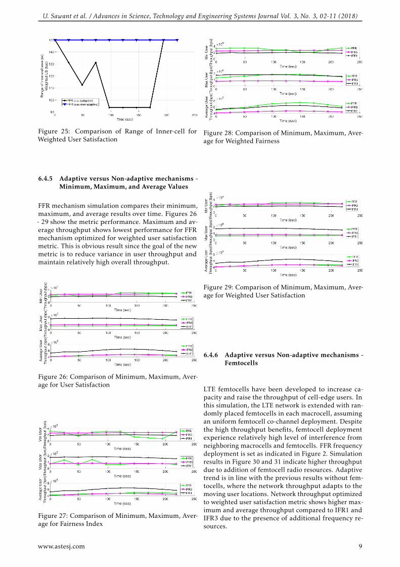
Figure 25: Comparison of Range of Inner-cell forWeighted User Satisfaction
6.4.5 Adaptive versus Non-adaptive mechanisms -Minimum, Maximum, and Average Values
FFR mechanism simulation compares their minimum,maximum, and average results over time. Figures 26- 29 show the metric performance. Maximum and av-erage throughput shows lowest performance for FFRmechanism optimized for weighted user satisfactionmetric. This is obvious result since the goal of the newmetric is to reduce variance in user throughput andmaintain relatively high overall throughput.
Figure 26: Comparison of Minimum, Maximum, Aver-age for User Satisfaction
Figure 27: Comparison of Minimum, Maximum, Aver-age for Fairness Index
Figure 28: Comparison of Minimum, Maximum, Aver-age for Weighted Fairness
Figure 29: Comparison of Minimum, Maximum, Aver-age for Weighted User Satisfaction
6.4.6 Adaptive versus Non-adaptive mechanisms -Femtocells
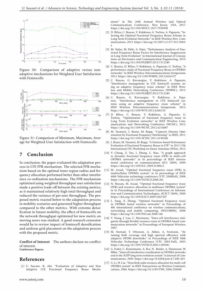
LTE femtocells have been developed to increase ca-pacity and raise the throughput of cell-edge users. Inthis simulation, the LTE network is extended with ran-domly placed femtocells in each macrocell, assumingan uniform femtocell co-channel deployment. Despitethe high throughput benefits, femtocell deploymentexperience relatively high level of interference fromneighboring macrocells and femtocells. FFR frequencydeployment is set as indicated in Figure 2. Simulationresults in Figure 30 and 31 indicate higher throughputdue to addition of femtocell radio resources. Adaptivetrend is in line with the previous results without fem-tocells, where the network throughput adapts to themoving user locations. Network throughput optimizedto weighted user satisfaction metric shows higher max-imum and average throughput compared to IFR1 andIFR3 due to the presence of additional frequency re-sources.
www.astesj.com 9
U. Sawant et al. / Advances in Science, Technology and Engineering Systems Journal Vol. 3, No. 3, 02-11 (2018)
Figure 30: Comparison of adaptive versus non-adaptive mechanisms for Weighted User Satisfactionwith Femtocells
Figure 31: Comparison of Minimum, Maximum, Aver-age for Weighted User Satisfaction with Femtocells
7 Conclusion
In conclusion, the paper evaluated the adaptation pro-cess in LTE FFR mechanism. The selected FFR mecha-nism based on the optimal inner region radius and fre-quency allocation performed better than other interfer-ence co-ordination mechanisms. The FFR mechanismoptimized using weighted throughput user satisfactionmade a positive trade-off between the existing metrics,as it maintained relatively high total throughput andreduced the variance of per-user throughput. The pro-posed metric reacted better to the adaptation processin mobility scenarios and generated higher throughputcompared to the other metrics. With extreme densi-fication in future mobility, the effect of femtocells onthe network throughput optimized for new metric onmoving users was studied. A good research extensionwould be to review impact of femtocell densificationand uniform grid placement on the adaptation processwith the proposed metric.
Conflict of Interest The authors declare no conflictof interest.Conference Papers:
References[1] U. Sawant, R. Akl, “Evaluation of Adaptive and Non
Adaptive LTE Fractional Frequency Reuse Mecha-
nisms” in The 26th Annual Wireless and OpticalCommunications Conference, New Jersey, USA, 2017.https://doi.org/10.1109/WOCC.2017.7928998
[2] D. Bilios, C. Bouras, V. Kokkinos, G. Tseliou, A. Papazois, “Se-lecting the Optimal Fractional Frequency Reuse Scheme inLong Term Evolution Networks” in IEEE Wireless Pers. Com-munications, 2013. https://doi.org/10.1007/s11277-012-0965-z
[3] M. Yadav, M. Palle, A. Hani, “Performance Analysis of Frac-tional Frequency Reuse Factor for Interference Suppressionin Long Term Evolution” in International Journal of Concep-tions on Electronics and Communication Engineering, 2015.https://doi.org/10.1109/PGSRET.2015.7312249
[4] C. Bouras, D. Bilios, V. Kokkinos, A. Papazois, G. Tseliou, “Aperformance study of Fractional Frequency Reuse in OFDMAnetworks” in IEEE Wireless Telecommunications Symposium,2012. https://doi.org/10.1109/WMNC.2012.6416137
[5] C. Bouras, G. Kavourgias, V. Kokkinos, A. Papazois,“Interference management in LTE femtocell systems us-ing an adaptive frequency reuse scheme” in IEEE Wire-less and Mobile Networking Conference (WMNC), 2012.https://doi.org/10.1109/PGSRET.2015.7312249
[6] C. Bouras, G. Kavourgias, V. Kokkinos, A. Papa-zois, “Interference management in LTE femtocell sys-tems using an adaptive frequency reuse scheme” inIEEE Wireless Telecommunications Symposium, 2012.https://doi.org/10.1109/WTS.2012.6266120
[7] D. Bilios, C. Bouras, V. Kokkinos, A. Papazois, G.Tseliou, “Optimization of fractional frequency reuse inLong Term Evolution networks” in IEEE Wireless Com-munications and Networking Conference (WCNC), 2012.https://doi.org/10.1109/WCNC.2012.6214087
[8] M. Taranetz, J. Ikuno, M. Rupp, “Capacity Density Opti-mization by Fractional Frequency Partitioning” in IEEE, 2011.https://doi.org/10.1109/ACSSC.2011.6190246
[9] J. Ikuno, M. Taranetz, M. Rupp, “A Fairness-based PerformanceEvaluation of Fractional Frequency Reuse in LTE” in 2013 17thInternational ITG Workshop on Smart Antennas (WSA), 2013.
[10] Y. Chang, Z. Tao, J. Zhang, C. Kuo, “A graph approachto dynamic fractional frequency reuse (FFR) in multi-cellOFDMA networks” in In proceedings of IEEE interna-tional conference on communications (ICC 2009), 2009.https://doi.org/10.1109/ICC.2009.5198612
[11] M. Assad, “Optimal fractional frequency reuse (FFR) inmulticellular OFDMA system” in In proceedings of IEEE68th Vehicular technology conference (VTC 2008Fall), 2008.https://doi.org/10.1109/VETECF.2008.381
[12] N. Hassan, M. Assad, “Optimal fractional frequency reuse(FFR) and resource allocation in multiuser OFDMA system”in In Proceedings of International Conference on Informa-tion and Communication Technologies, (ICICT 2009), 2009.https://doi.org/10.1109/ICICT.2009.5267207
[13] L. Fang, X. Zhang, “Optimal fractional frequency reusein OFDMA based wireless networks” in Proceedings of4th international conference on wireless communications,networking and mobile computing, (WiCOM08), 2008.https://doi.org/10.1109/WiCom.2008.166
[14] Y. Xiang, J. Luo, C. Hartmann, “Inter-cell interference miti-gation through flexible resource reuse in OFDMA based com-munication networks” in Proceedings of European Wireless,2007.
[15] M. Sternad, T. Ottosson, A. Ahlen, A. Svensson, “At-taining both coverage and high spectral efficiency withadaptive OFDM downlinks” in Proceedings of IEEE 58thVehicular Technology Conference (VTC 2003-Fall), 2003.https://doi.org/10.1109/VETECF.2003.1285981
[16] G. Fodor, C. Koutsimanis, A. Rcz, N. Reider, A. Simonsson, W.Mller, “Intercell interference coordination in OFDMA networksand in the 3GPP long term evolution system” in Journal of Com-munications, 2009. https://doi.org/10.4304/jcm.4.7.445-453
[17] G. Li, H. Liu, “Downlink radio resource allocation for multi-cellOFDMA system” in IEEE Transactions on Wireless Communi-cations, 2006. https://doi.org/10.1109/TWC.2006.256968
www.astesj.com 10
U. Sawant et al. / Advances in Science, Technology and Engineering Systems Journal Vol. 3, No. 3, 02-11 (2018)
[18] P. Godlewski, M. Maqbool, M. Coupechoux, J. Ke-lif, “Analytical evaluation of various frequency reuseschemes in cellular OFDMA networks” in Proceedingsof 3rd international conference on performance evalu-ation methodologies and tools (Valuetools 2008), 2008.https://doi.org/10.1016/j.peva.2009.08.001
[19] J. Lim, R. Badlishah, M. Jusoh, “LTE-fractional frequencyreuse (FFR) optimization with femtocell network” in 2nd In-ternational Conference on Electronic Design (ICED), 2014.https://doi.org/10.1109/ICED.2014.7015863
[20] H. Elfadil, M. Ali, M. Abas, “Fractional frequencyreuse in LTE networks” in 2015 2nd World Symposiumon Web Applications and Networking (WSWAN), 2015.https://doi.org/10.1109/WSWAN.2015.7210297
[21] P. Yen, Q. Zhan, H. Minn, “New Fractional FrequencyReuse Patterns for Multi-Cell Systems in Time-VaryingChannels” in International Journal of Conceptionson Electronics and Communication Engineering, 2015.https://doi.org/10.1109/LWC.2015.2404787
[22] S. Shahsavari, N. Akar, B. Hossein Khalaj, “Joint Cell Mutingand User Scheduling in Multi-Cell Networks with TemporalFairness” in CoRR, 2016.
[23] H. Chang, I. Rubin, “Optimal Downlink and UplinkFractional Frequency Reuse in Cellular Wireless Net-works” in IEEE Transactions on Vehicular Technology, 2015.https://doi.org/10.1109/TVT.2015.2425356
[24] I. Mahmoud, O. Elgzzar, S. Hashima, “An accurate modelof worst case signal to interference ratio for frequency
reuse cellular systems” in 2016 11th International Confer-ence on Computer Engineering and Systems (ICCES), 2016.https://doi.org/10.1109/ICCES.2016.7822037
[25] N. Saquib, E. Hossain, D. I. Kim, “Fractional frequencyreuse for interference management in LTE-AdvancedHetNets”, in IEEE Wireless Communications, 2013.https://doi.org/10.1109/MWC.2013.6507402
[26] P. Lee, T. Lee, J. Jeong, J. Shin, “Interference Manage-ment in LTE Femtocell Systems Using Fractional Fre-quency Reuse” in The 12th International Conferenceon Advanced Communication Technology (ICACT), 2010.https://doi.org/10.1109/PGSRET.2015.7312249
[27] Technical Specification Group RAN, “TechnicalSpecification Group RAN, E-UTRA; LTE RF sys-tem scenarios” in 3GPP Tech. Rep. TS 36.942, 2008.https://doi.org/10.1109/PGSRET.2015.7312249
[28] C. Bouras, V. Kokkinos, A. Papazois, G. Tseliou, “FractionalFrequency Reuse in Integrated Femtocell/Macrocell Environ-ments” in IEEE WWIC, 2013. https://doi.org/10.1007/978-3-642-38401-1 18
[29] R. Jain, D. Chiu, W. Hawe, “A Quantitative Measure of Fair-ness And Discrimination for Resource Allocation in SharedComputer System” in DEC Technical Report 301, 1984.https://doi.org/10.1109/PGSRET.2015.7312249
[30] Research Unit 6, “FFR Scheme Selection Mechanism”, 2013.http://ru6.cti.gr/ru6/FFR selection mechanism.zip
www.astesj.com 11