Embed Size (px)
Citation preview
Proceedings of ASME Turbo Expo 2008: Power for Land, Sea and Air GT 2008
June 9-13, Berlin, Germany
GT2008-51377
ADAPTING GAS TURBINES TO ZERO EMISSION OXY-FUEL POWER PLANTS
Roger E. Anderson, Scott MacAdam, Fermin Viteri
Clean Energy Systems, Inc.
Daniel O. Davies, James P. Downs Andrew Paliszewski Florida Turbine Technologies, Inc. Siemens Power Generation, Inc. ABSTRACT Future power plants will require some type of carbon capture and storage (CCS) system to mitigate carbon dioxide (CO2) emissions. The most promising technologies for CCS are: oxy-fuel (O-F) combustion, pre-combustion capture, and post-combustion capture. This paper discusses the recent work con-ducted by Siemens Power Generation, Florida Turbine Tech-nologies, Inc. (FTT) and Clean Energy Systems, Inc. (CES) in adapting high temperature gas turbines to use CES’s drive gases in high-efficiency O-F zero emission power plants (ZEPPs). CES’s O-F cycle features high-pressure combustion of fuel with oxygen (O2) in the presence of recycled coolant (water, steam or CO2) to produce drive gases composed predominantly of steam and CO2. This cycle provides the unique capability to capture nearly pure CO2 and trace by-products by simple con-densation of the steam. An attractive O-F power cycle uses high, intermediate and low pressure turbines (HPT, IPT and LPT, respectively). The HPT may be based on either current commercial or advanced steam turbine technology. Low pressure steam turbine technology is readily applicable to the LPT. To achieve high efficiencies, an IPT is necessary and efficiency increases with inlet tempera-ture. The high-temperature IPT’s necessitate advanced turbine materials and cooling technology. O-F plants have an abun-dance of water, cool steam ~200ºC (400ºF) and CO2 that can be used as cooling fluids within the combustor and IPT systems. For the “First Generation” ZEPP, a General Electric J79 tur-bine, minus the compressor, to be driven directly by CES’s 170 MWt high-pressure oxy-fuel combustor (gas generator), has been adapted. A modest inlet gas temperature of 760ºC (1400ºF) was selected to eliminate the need for turbine cooling. The J79 turbine operating on natural gas delivers 32 MWe and incorporates a single-stage free-turbine that generates an addi-tional 11 MWe. When an HPT and an LPT are added, the net output power (accounting for losses) becomes 60 MWe at 30% efficiency based on lower heating value (LHV), including the
parasitic loads for O2 separation and compression and for CO2 capture and compression to 151.5 bar (2200 psia). For an inlet temperature of 927ºC (1700ºF), the nominal value, the net out-put power is 70 MWe at 34% efficiency (LHV). FTT and CES are evaluating a “Second Generation“ IPT with a gas inlet temperature of 1260ºC (2300ºF). Predicted perform-ance values for these plants incorporating the HPT, IPT and the LPT are: output power of approximately 100-200 MWe with an efficiency of 40 to 45%. The “Third Generation” IPT for 2015+ power plants will be based on the development of very high temperature turbines having an inlet temperature goal of 1760ºC (3200ºF). Recent DOE/CES studies project such plants will have LHV efficien-cies in the 50% range for natural gas and HHV efficiencies near 40% for gasified coal [ ]1 . 1 INTRODUCTION In 1999, the California Energy Commission (CEC) awarded CES an Energy Innovation Small Grant to assist in the con-struction of a laboratory-scale oxy-combustor. Under that pro-gram, CES built and tested a lab-scale combustor at tempera-tures up to 1482ºC (2700ºF) and pressures up to 20.7 bar (300 psia). The combustor operated repeatedly, reliably, and stably on O2, CH4, and water during more than 75 starts with individ-ual test durations up to 48 minutes. This program experimen-tally established the "proof of principle" for the new method of producing clean, high-energy drive gases for the generation of electrical power. The experimental work was completed in January of 2001, and details are given in the final report [ ]2 . In September 2000, the U.S. Department of Energy (DOE) funded CES under the Vision 21 Program to design, fabricate, and test a 20 MWt combustor to operate on O2, CH4, and water. That oxy-fuel combustor was 0.102 m (4 in.) inside diameter and was tested during late 2002 and early 2003. The tests suc-cessfully demonstrated operation at temperatures ranging from
Copyright © 2008 by Clean Energy Systems, Inc. 1
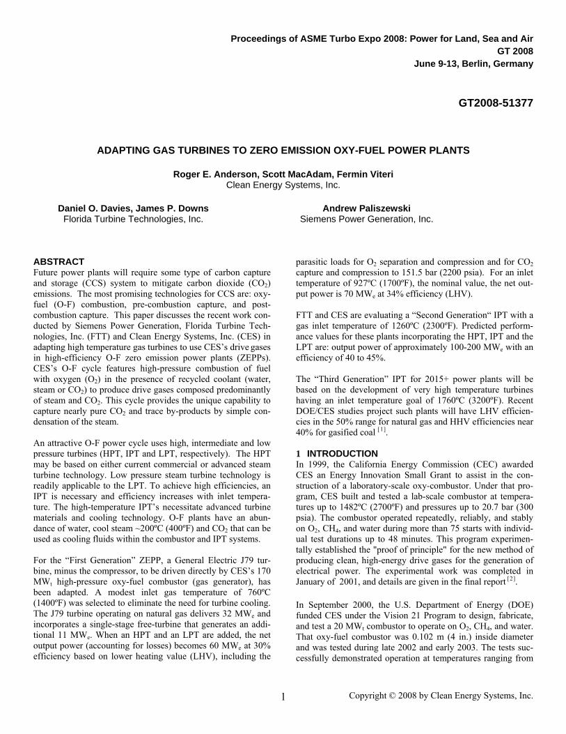
316-1649°C (600-3000°F) and at pressures from 75.8 to 106.2 bar (1100-1540 psia). The combustor operated successfully at both low power (20% of rated power) and full power (20 MWt) in more than 95 tests. Details are given in the final program re-port [ ]3 . In early 2002, the CEC awarded CES $2 million to fabricate and operate a natural gas fired zero-emission demonstration power plant using CES’s demonstrated gas generator. The goals of that project were to evaluate the durability of the com-bustor and identify desirable design refinements. In August 2003 CES acquired the idle 5 MWe “Kimberlina” biomass power plant near Bakersfield, California from AES, Inc. The CEC approved this site for the demonstration project, and pro-vided $2 million in supplemental funding. Subsequent to the acquisition of the Kimberlina power plant, CES designed a complete control system for the 20 MWt combustor and inte-grated that system with the combustor module (Figure 1).
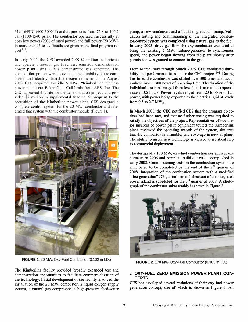
FIGURE 2. 170 MWt Oxy-Fuel Combustor (0.305 m I.D.) The Kimberlina facility provided broadly expanded test and demonstration opportunities to facilitate commercialization of the technology. Initial development of the facility involved the installation of the 20 MWt combustor, a liquid oxygen supply system, a natural gas compressor, a high-pressure feed-water
pump, a new condenser, and a liquid ring vacuum pump. Vali-dation testing and commissioning of the integrated combus-tor/control system was completed using natural gas as the fuel. In early 2005, drive gas from the oxy-combustor was used to bring the existing 5 MWe turbine-generator to synchronous speed, and power began flowing from the plant shortly after permission was granted to connect to the grid.
The Kimberlina facility provided broadly expanded test and demonstration opportunities to facilitate commercialization of the technology. Initial development of the facility involved the installation of the 20 MW
From March 2005 through March 2006, CES conducted dura-bility and performance tests under the CEC project [ ]44 . During this time, the combustor was started over 300 times and accu-mulated over 1,300 hours of operating time. The duration of the individual test runs ranged from less than 1 minute to approxi-mately 105 hours. Power levels ranged from 20 to 88% of full power, with power being exported to the electrical grid at levels from 0.5 to 2.7 MWe.
From March 2005 through March 2006, CES conducted dura-bility and performance tests under the CEC project
In March 2006, the CEC notified CES that the program objec-tives had been met, and that no further testing was required to satisfy the objectives of the project. Representatives of two ma-jor insurers of power plant equipment toured the Kimberlina plant, reviewed the operating records of the system, declared that the combustor is insurable, and coverage is now in place. The ability to insure new technology is viewed as a critical step to commercial deployment.
In March 2006, the CEC notified CES that the program objec-tives had been met, and that no further testing was required to satisfy the objectives of the project. Representatives of two ma-jor insurers of power plant equipment toured the Kimberlina plant, reviewed the operating records of the system, declared that the combustor is insurable, and coverage is now in place. The ability to insure new technology is viewed as a critical step to commercial deployment. The design of a 170 MWt oxy-fuel combustion system was un-dertaken in 2006 and complete build out was accomplished in early 2008. Commissioning tests on the combustion system are anticipated to be completed by the end of the 2nd quarter of 2008. Integration of the combustion system with a modified “first generation” J79 gas turbine and checkout of the integrated power island is scheduled for the 3rd quarter of 2008. A photo-graph of the combustor subassembly is shown in Figure 2.
The design of a 170 MW
2 OXY-FUEL ZERO EMISSION POWER PLANT CON-
CEPTS 2 OXY-FUEL ZERO EMISSION POWER PLANT CON-
CEPTS CES has developed several variations of their oxy-fuel power generation concept, one of which is shown in Figure 3. All CES has developed several variations of their oxy-fuel power generation concept, one of which is shown in Figure 3. All t combustor, a liquid oxygen supply
system, a natural gas compressor, a high-pressure feed-water
pump, a new condenser, and a liquid ring vacuum pump. Vali-dation testing and commissioning of the integrated combus-tor/control system was completed using natural gas as the fuel. In early 2005, drive gas from the oxy-combustor was used to bring the existing 5 MWe turbine-generator to synchronous speed, and power began flowing from the plant shortly after permission was granted to connect to the grid.
[ ]. During this time, the combustor was started over 300 times and accu-mulated over 1,300 hours of operating time. The duration of the individual test runs ranged from less than 1 minute to approxi-mately 105 hours. Power levels ranged from 20 to 88% of full power, with power being exported to the electrical grid at levels from 0.5 to 2.7 MWe.
t oxy-fuel combustion system was un-dertaken in 2006 and complete build out was accomplished in early 2008. Commissioning tests on the combustion system are anticipated to be completed by the end of the 2nd quarter of 2008. Integration of the combustion system with a modified “first generation” J79 gas turbine and checkout of the integrated power island is scheduled for the 3rd quarter of 2008. A photo-graph of the combustor subassembly is shown in Figure 2.
FIGURE 1. 20 MWt Oxy-Fuel Combustor (0.102 m I.D.)
Copyright © 2008 by Clean Energy Systems, Inc. 2
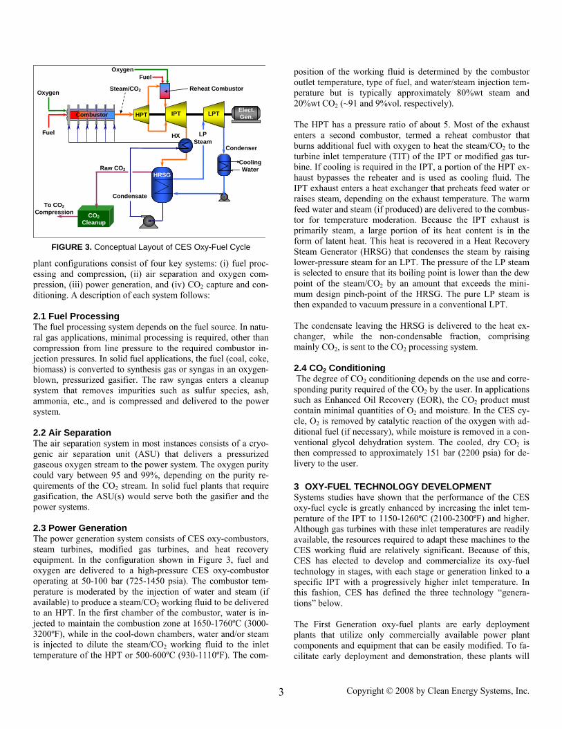
plant configurations consist of four key systems: (i) fuel proc-essing and compression, (ii) air separation and oxygen com-pression, (iii) power generation, and (iv) CO2 capture and con-ditioning. A description of each system follows: 2.1 Fuel Processing The fuel processing system depends on the fuel source. In natu-ral gas applications, minimal processing is required, other than compression from line pressure to the required combustor in-jection pressures. In solid fuel applications, the fuel (coal, coke, biomass) is converted to synthesis gas or syngas in an oxygen-blown, pressurized gasifier. The raw syngas enters a cleanup system that removes impurities such as sulfur species, ash, ammonia, etc., and is compressed and delivered to the power system. 2.2 Air Separation The air separation system in most instances consists of a cryo-genic air separation unit (ASU) that delivers a pressurized gaseous oxygen stream to the power system. The oxygen purity could vary between 95 and 99%, depending on the purity re-quirements of the CO2 stream. In solid fuel plants that require gasification, the ASU(s) would serve both the gasifier and the power systems. 2.3 Power Generation The power generation system consists of CES oxy-combustors, steam turbines, modified gas turbines, and heat recovery equipment. In the configuration shown in Figure 3, fuel and oxygen are delivered to a high-pressure CES oxy-combustor operating at 50-100 bar (725-1450 psia). The combustor tem-perature is moderated by the injection of water and steam (if available) to produce a steam/CO2 working fluid to be delivered to an HPT. In the first chamber of the combustor, water is in-jected to maintain the combustion zone at 1650-1760ºC (3000-3200ºF), while in the cool-down chambers, water and/or steam is injected to dilute the steam/CO2 working fluid to the inlet temperature of the HPT or 500-600ºC (930-1110ºF). The com-
position of the working fluid is determined by the combustor outlet temperature, type of fuel, and water/steam injection tem-perature but is typically approximately 80%wt steam and 20%wt CO2 (~91 and 9%vol. respectively). The HPT has a pressure ratio of about 5. Most of the exhaust enters a second combustor, termed a reheat combustor that burns additional fuel with oxygen to heat the steam/CO2 to the turbine inlet temperature (TIT) of the IPT or modified gas tur-bine. If cooling is required in the IPT, a portion of the HPT ex-haust bypasses the reheater and is used as cooling fluid. The IPT exhaust enters a heat exchanger that preheats feed water or raises steam, depending on the exhaust temperature. The warm feed water and steam (if produced) are delivered to the combus-tor for temperature moderation. Because the IPT exhaust is primarily steam, a large portion of its heat content is in the form of latent heat. This heat is recovered in a Heat Recovery Steam Generator (HRSG) that condenses the steam by raising lower-pressure steam for an LPT. The pressure of the LP steam is selected to ensure that its boiling point is lower than the dew point of the steam/CO2 by an amount that exceeds the mini-mum design pinch-point of the HRSG. The pure LP steam is then expanded to vacuum pressure in a conventional LPT. The condensate leaving the HRSG is delivered to the heat ex-changer, while the non-condensable fraction, comprising mainly CO2, is sent to the CO2 processing system. 2.4 CO2 Conditioning The degree of CO2 conditioning depends on the use and corre-sponding purity required of the CO2 by the user. In applications such as Enhanced Oil Recovery (EOR), the CO2 product must contain minimal quantities of O2 and moisture. In the CES cy-cle, O2 is removed by catalytic reaction of the oxygen with ad-ditional fuel (if necessary), while moisture is removed in a con-ventional glycol dehydration system. The cooled, dry CO2 is then compressed to approximately 151 bar (2200 psia) for de-livery to the user. 3 OXY-FUEL TECHNOLOGY DEVELOPMENT Systems studies have shown that the performance of the CES oxy-fuel cycle is greatly enhanced by increasing the inlet tem-perature of the IPT to 1150-1260ºC (2100-2300ºF) and higher. Although gas turbines with these inlet temperatures are readily available, the resources required to adapt these machines to the CES working fluid are relatively significant. Because of this, CES has elected to develop and commercialize its oxy-fuel technology in stages, with each stage or generation linked to a specific IPT with a progressively higher inlet temperature. In this fashion, CES has defined the three technology “genera-tions” below. The First Generation oxy-fuel plants are early deployment plants that utilize only commercially available power plant components and equipment that can be easily modified. To fa-cilitate early deployment and demonstration, these plants will
FIGURE 3. Conceptual Layout of CES Oxy-Fuel Cycle
Fuel
Combustor HPT Elect.Gen.
CO2 Cleanup
Cooling Water
Oxygen
LPT IPT
OxygenFuel
Reheat Combustor
HRSGRaw CO2
Condensate
Steam/CO2
LP Steam
To CO2 Compression
Condenser
HX
Copyright © 2008 by Clean Energy Systems, Inc. 3
be in the ~50 MWe size range and will be located where a reve-nue stream can be generated from the CO2 by-product. Loca-tions will likely be near oil or gas producing areas where the CO2 can be used for enhanced oil recovery (EOR) or enhanced gas recovery (EGR). The plants will utilize a modified GE J79 gas turbine from an LMA1500 power system that CES has been adapting for its steam/CO2 working fluid. An in-depth discus-sion of the effort to modify the J79 to operate at inlet tempera-tures in the range of 760-927ºC (1400-1700ºF) is provided be-low. These plants could use natural gas or syngas as the fuel. In the latter case, the plant will include an O2-blown gasifier in the ~200 MWt size range, such as the SFG-200 offered by Siemens Fuel Gasification [5]. The capital costs of the syngas-based plants will be considerably higher than the natural gas plants, but this will be offset by the significantly lower fuel costs and higher CO2 revenues. CES envisions that the First Generation plants will be operational in the 2011 timeframe. However, the combustor and J79 module will be available for commissioning at sites that already have an oxygen supply by late 2008.
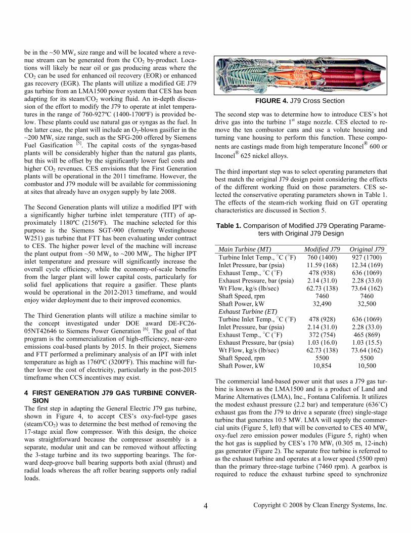
FIGURE 4. J79 Cross Section
The Second Generation plants will utilize a modified IPT with a significantly higher turbine inlet temperature (TIT) of ap-proximately 1180ºC (2156ºF). The machine selected for this purpose is the Siemens SGT-900 (formerly Westinghouse W251) gas turbine that FTT has been evaluating under contract to CES. The higher power level of the machine will increase the plant output from ~50 MWe to ~200 MWe. The higher IPT inlet temperature and pressure will significantly increase the overall cycle efficiency, while the economy-of-scale benefits from the larger plant will lower capital costs, particularly for solid fuel applications that require a gasifier. These plants would be operational in the 2012-2013 timeframe, and would enjoy wider deployment due to their improved economics. The Third Generation plants will utilize a machine similar to the concept investigated under DOE award DE-FC26-05NT42646 to Siemens Power Generation [6]. The goal of that program is the commercialization of high-efficiency, near-zero emissions coal-based plants by 2015. In their project, Siemens and FTT performed a preliminary analysis of an IPT with inlet temperature as high as 1760ºC (3200ºF). This machine will fur-ther lower the cost of electricity, particularly in the post-2015 timeframe when CCS incentives may exist. 4 FIRST GENERATION J79 GAS TURBINE CONVER-
SION The first step in adapting the General Electric J79 gas turbine, shown in Figure 4, to accept CES’s oxy-fuel-type gases (steam/CO2) was to determine the best method of removing the 17-stage axial flow compressor. With this design, the choice was straightforward because the compressor assembly is a separate, modular unit and can be removed without affecting the 3-stage turbine and its two supporting bearings. The for-ward deep-groove ball bearing supports both axial (thrust) and radial loads whereas the aft roller bearing supports only radial loads.
The second step was to determine how to introduce CES’s hot drive gas into the turbine 1st stage nozzle. CES elected to re-move the ten combustor cans and use a volute housing and turning vane housing to perform this function. These compo-nents are castings made from high temperature Inconel® 600 or Inconel® 625 nickel alloys. The third important step was to select operating parameters that best match the original J79 design point considering the effects of the different working fluid on those parameters. CES se-lected the conservative operating parameters shown in Table 1. The effects of the steam-rich working fluid on GT operating characteristics are discussed in Section 5. Table 1. Comparison of Modified J79 Operating Parame-
ters with Original J79 Design
Main Turbine (MT) Modified J79 Original J79Turbine Inlet Temp., ○C (○F) 760 (1400) 927 (1700) Inlet Pressure, bar (psia) 11.59 (168) 12.34 (169) Exhaust Temp., ○C (○F) 478 (938) 636 (1069) Exhaust Pressure, bar (psia) 2.14 (31.0) 2.28 (33.0) Wt Flow, kg/s (lb/sec) 62.73 (138) 73.64 (162) Shaft Speed, rpm 7460 7460 Shaft Power, kW 32,490 32,500 Exhaust Turbine (ET) Turbine Inlet Temp., ○C (○F) 478 (928) 636 (1069) Inlet Pressure, bar (psia) 2.14 (31.0) 2.28 (33.0) Exhaust Temp., ○C (○F) 372 (754) 465 (869) Exhaust Pressure, bar (psia) 1.03 (16.0) 1.03 (15.5) Wt Flow, kg/s (lb/sec) 62.73 (138) 73.64 (162) Shaft Speed, rpm 5500 5500 Shaft Power, kW 10,854 10,500
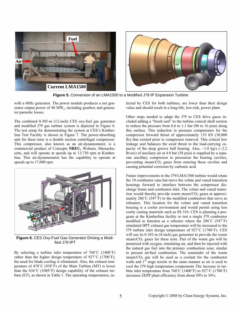
The commercial land-based power unit that uses a J79 gas tur-bine is known as the LMA1500 and is a product of Land and Marine Alternatives (LMA), Inc., Fontana California. It utilizes the modest exhaust pressure (2.2 bar) and temperature (636˚C) exhaust gas from the J79 to drive a separate (free) single-stage turbine that generates 10.5 MW. LMA will supply the commer-cial units (Figure 5, left) that will be converted to CES 40 MWe oxy-fuel zero emission power modules (Figure 5, right) when the hot gas is supplied by CES’s 170 MWt (0.305 m, 12-inch) gas generator (Figure 2). The separate free turbine is referred to as the exhaust turbine and operates at a lower speed (5500 rpm) than the primary three-stage turbine (7460 rpm). A gearbox is required to reduce the exhaust turbine speed to synchronize
Copyright © 2008 by Clean Energy Systems, Inc. 4
Fuel
Figure 5. Conversion of an LMA1500 to a Modified J79 IP Expansion Turbine
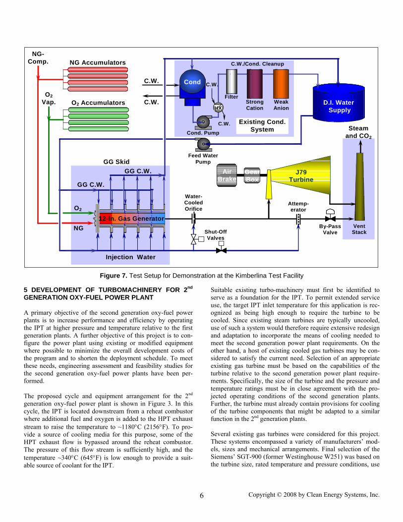
with a 60Hz generator. The power module produces a net gen-erator output power of 40 MWe, including gearbox and genera-tor parasitic losses. The combined 0.305-m (12-inch) CES oxy-fuel gas generator and modified J79 gas turbine system is depicted in Figure 6. The test setup for demonstrating the system at CES’s Kimber-lina Test Facility is shown in Figure 7. The power-absorbing unit for these tests is a double suction centrifugal compressor. This compressor, also known as an air-dynamometer, is a commercial product of Concepts NREC, Woburn, Massachu-setts, and will operate at speeds up to 13,730 rpm at Kimber-lina. This air-dynamometer has the capability to operate at speeds up to 17,000 rpm.
By selecting a turbine inlet temperature of 760○C (1400○F) rather than the higher design temperature of 927○C (1700○F), the need for blade cooling is eliminated. Also, the exhaust tem-perature of 478○C (938○F) of the Main Turbine (MT) is lower than the 636○C (1069○F) design capability of the exhaust tur-bine (ET), as shown in Table 1. The operating temperatures, se-
lected by CES for both turbines, are lower than their design value and should result in a long-life, low-risk, power plant. Other steps needed to adapt the J79 to CES drive gases in-cluded adding a “brush seal” to the turbine conical shaft section to reduce the pressure from 6.6 to 1.1 bar (96 to 16 psia) along this surface. This reduction in pressure compensates for the compressor forward thrust of approximately 133 kN (30,000 lbf) that existed prior to compressor removal. This critical low leakage seal balances the axial thrust to the load-carrying ca-pacity of the deep groove ball bearing. Also, ~1.0 kg/s (~2.2 lb/sec) of auxiliary air at 4.0 bar (58 psia) is supplied by a sepa-rate ancillary compressor to pressurize the bearing cavities, preventing steam/CO2 gases from entering these cavities and causing potential corrosion by carbonic acid. Future improvements to the J79/LMA1500 turbine would retain the 10 combustor cans but move the volute and vaned transition housings forward to interface between the compressor dis-charge frame and combustor inlet. The volute and vaned transi-tion would thereby provide warm steam/CO2 gases at approxi-mately 286˚C (547○F) to the modified combustors that serve as reheaters. This location for the volute and vaned transition housing is a cooler environment and would permit using less costly casting materials such as SS 316. CES is planning a pro-gram at the Kimberlina facility to test a single J79 combustor modified to function as a reheater where the 286˚C (547○F) simulated HPT exhaust gas temperature will be increased to the J79 turbine inlet design temperature of 927˚C (1700○F). CES will use its 0.102-m (4-inch) gas generator to provide the warm steam/CO2 gases for these tests. Part of the warm gas will be premixed with oxygen, simulating air, and then be injected with the natural gas fuel into the primary combustion zone, similar to present air/fuel combustion. The remainder of the warm steam/CO2 gas will be used as a coolant for the combustor walls and 1st stage nozzle in the same manner as air is used to cool the J79 high temperature components The increase in tur-bine inlet temperature from 760˚C (1400○F) to 927˚C (1700○F) increases ZEPP plant efficiency from about 30% to 34%.
Air
Current LM1500 Current LMA1500
Figure 6. CES Oxy-Fuel Gas Generator Driving a Modi-fied J79 IPT
Copyright © 2008 by Clean Energy Systems, Inc. 5
Copyright © 2008 by Clean Energy Systems, Inc. 6
Figure 7. Test Setup for Demonstration at the Kimberlina Test Facility
GG Skid
Injection Water
12-in. Gas Generator
O2
NG
GearBox
AirBrake
J79 Turbine
GG C.W.
Water-CooledOrifice
By-PassValve
Feed WaterPump
Shut-OffValves
O2 Accumulators
NG Accumulators
D.I. Water Supply
C.W./Cond. Cleanup
FilterStrong Cation
Weak Anion
GG C.W.
Cond. Pump
VentStack
Attemp- erator
C.W.
C.W.
Cond
Existing Cond. System
HX
C.W.
C.W.
NG- Comp.
O2 Vap.
Steamand CO2
5 DEVELOPMENT OF TURBOMACHINERY FOR 2nd GENERATION OXY-FUEL POWER PLANT A primary objective of the second generation oxy-fuel power plants is to increase performance and efficiency by operating the IPT at higher pressure and temperature relative to the first generation plants. A further objective of this project is to con-figure the power plant using existing or modified equipment where possible to minimize the overall development costs of the program and to shorten the deployment schedule. To meet these needs, engineering assessment and feasibility studies for the second generation oxy-fuel power plants have been per-formed. The proposed cycle and equipment arrangement for the 2nd generation oxy-fuel power plant is shown in Figure 3. In this cycle, the IPT is located downstream from a reheat combustor where additional fuel and oxygen is added to the HPT exhaust stream to raise the temperature to ~1180°C (2156°F). To pro-vide a source of cooling media for this purpose, some of the HPT exhaust flow is bypassed around the reheat combustor. The pressure of this flow stream is sufficiently high, and the temperature ~340°C (645°F) is low enough to provide a suit-able source of coolant for the IPT.
Suitable existing turbo-machinery must first be identified to serve as a foundation for the IPT. To permit extended service use, the target IPT inlet temperature for this application is rec-ognized as being high enough to require the turbine to be cooled. Since existing steam turbines are typically uncooled, use of such a system would therefore require extensive redesign and adaptation to incorporate the means of cooling needed to meet the second generation power plant requirements. On the other hand, a host of existing cooled gas turbines may be con-sidered to satisfy the current need. Selection of an appropriate existing gas turbine must be based on the capabilities of the turbine relative to the second generation power plant require-ments. Specifically, the size of the turbine and the pressure and temperature ratings must be in close agreement with the pro-jected operating conditions of the second generation plants. Further, the turbine must already contain provisions for cooling of the turbine components that might be adapted to a similar function in the 2nd generation plants. Several existing gas turbines were considered for this project. These systems encompassed a variety of manufacturers’ mod-els, sizes and mechanical arrangements. Final selection of the Siemens’ SGT-900 (former Westinghouse W251) was based on the turbine size, rated temperature and pressure conditions, use
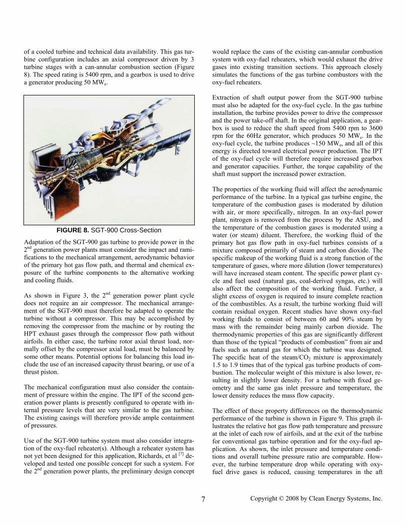
of a cooled turbine and technical data availability. This gas tur-bine configuration includes an axial compressor driven by 3 turbine stages with a can-annular combustion section (Figure 8). The speed rating is 5400 rpm, and a gearbox is used to drive a generator producing 50 MWe.
Adaptation of the SGT-900 gas turbine to provide power in the 2nd generation power plants must consider the impact and rami-fications to the mechanical arrangement, aerodynamic behavior of the primary hot gas flow path, and thermal and chemical ex-posure of the turbine components to the alternative working and cooling fluids. As shown in Figure 3, the 2nd generation power plant cycle does not require an air compressor. The mechanical arrange-ment of the SGT-900 must therefore be adapted to operate the turbine without a compressor. This may be accomplished by removing the compressor from the machine or by routing the HPT exhaust gases through the compressor flow path without airfoils. In either case, the turbine rotor axial thrust load, nor-mally offset by the compressor axial load, must be balanced by some other means. Potential options for balancing this load in-clude the use of an increased capacity thrust bearing, or use of a thrust piston. The mechanical configuration must also consider the contain-ment of pressure within the engine. The IPT of the second gen-eration power plants is presently configured to operate with in-ternal pressure levels that are very similar to the gas turbine. The existing casings will therefore provide ample containment of pressures. Use of the SGT-900 turbine system must also consider integra-tion of the oxy-fuel reheater(s). Although a reheater system has not yet been designed for this application, Richards, et al [7] de-veloped and tested one possible concept for such a system. For the 2nd generation power plants, the preliminary design concept
would replace the cans of the existing can-annular combustion system with oxy-fuel reheaters, which would exhaust the drive gases into existing transition sections. This approach closely simulates the functions of the gas turbine combustors with the oxy-fuel reheaters. Extraction of shaft output power from the SGT-900 turbine must also be adapted for the oxy-fuel cycle. In the gas turbine installation, the turbine provides power to drive the compressor and the power take-off shaft. In the original application, a gear-box is used to reduce the shaft speed from 5400 rpm to 3600 rpm for the 60Hz generator, which produces 50 MWe. In the oxy-fuel cycle, the turbine produces ~150 MWe, and all of this energy is directed toward electrical power production. The IPT of the oxy-fuel cycle will therefore require increased gearbox and generator capacities. Further, the torque capability of the shaft must support the increased power extraction. The properties of the working fluid will affect the aerodynamic performance of the turbine. In a typical gas turbine engine, the temperature of the combustion gases is moderated by dilution with air, or more specifically, nitrogen. In an oxy-fuel power plant, nitrogen is removed from the process by the ASU, and the temperature of the combustion gases is moderated using a water (or steam) diluent. Therefore, the working fluid of the primary hot gas flow path in oxy-fuel turbines consists of a mixture composed primarily of steam and carbon dioxide. The specific makeup of the working fluid is a strong function of the temperature of gases, where more dilution (lower temperatures) will have increased steam content. The specific power plant cy-cle and fuel used (natural gas, coal-derived syngas, etc.) will also affect the composition of the working fluid. Further, a slight excess of oxygen is required to insure complete reaction of the combustibles. As a result, the turbine working fluid will contain residual oxygen. Recent studies have shown oxy-fuel working fluids to consist of between 60 and 90% steam by mass with the remainder being mainly carbon dioxide. The thermodynamic properties of this gas are significantly different than those of the typical “products of combustion” from air and fuels such as natural gas for which the turbine was designed. The specific heat of the steam/CO2 mixture is approximately 1.5 to 1.9 times that of the typical gas turbine products of com-bustion. The molecular weight of this mixture is also lower, re-sulting in slightly lower density. For a turbine with fixed ge-ometry and the same gas inlet pressure and temperature, the lower density reduces the mass flow capacity.
FIGURE 8. SGT-900 Cross-Section
The effect of these property differences on the thermodynamic performance of the turbine is shown in Figure 9. This graph il-lustrates the relative hot gas flow path temperature and pressure at the inlet of each row of airfoils, and at the exit of the turbine for conventional gas turbine operation and for the oxy-fuel ap-plication. As shown, the inlet pressure and temperature condi-tions and overall turbine pressure ratio are comparable. How-ever, the turbine temperature drop while operating with oxy-fuel drive gases is reduced, causing temperatures in the aft
Copyright © 2008 by Clean Energy Systems, Inc. 7
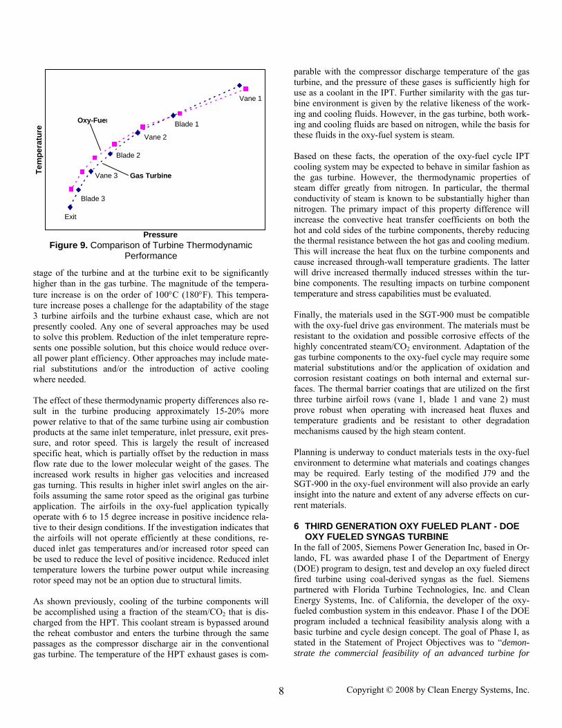
Figure 9. Comparison of Turbine Thermodynamic Performance
stage of the turbine and at the turbine exit to be significantly higher than in the gas turbine. The magnitude of the tempera-ture increase is on the order of 100°C (180°F). This tempera-ture increase poses a challenge for the adaptability of the stage 3 turbine airfoils and the turbine exhaust case, which are not presently cooled. Any one of several approaches may be used to solve this problem. Reduction of the inlet temperature repre-sents one possible solution, but this choice would reduce over-all power plant efficiency. Other approaches may include mate-rial substitutions and/or the introduction of active cooling where needed. The effect of these thermodynamic property differences also re-sult in the turbine producing approximately 15-20% more power relative to that of the same turbine using air combustion
roducts at the same inlet temperature, inlet pressure, exit pres-
t while increasing tor speed may not be an option due to structural limits.
e gas gh for s tur-
e work-work-
s for
on as
ies of ermal r than
will h the ucing
mpatible
in the oxy-fuel
ERATION OXY FUELED PLANT - DOE
r-
psure, and rotor speed. This is largely the result of increased specific heat, which is partially offset by the reduction in mass flow rate due to the lower molecular weight of the gases. The increased work results in higher gas velocities and increased gas turning. This results in higher inlet swirl angles on the air-foils assuming the same rotor speed as the original gas turbine application. The airfoils in the oxy-fuel application typically operate with 6 to 15 degree increase in positive incidence rela-tive to their design conditions. If the investigation indicates that the airfoils will not operate efficiently at these conditions, re-duced inlet gas temperatures and/or increased rotor speed can be used to reduce the level of positive incidence. Reduced inlet temperature lowers the turbine power outpuro As shown previously, cooling of the turbine components will be accomplished using a fraction of the steam/CO2 that is dis-charged from the HPT. This coolant stream is bypassed around the reheat combustor and enters the turbine through the same passages as the compressor discharge air in the conventional gas turbine. The temperature of the HPT exhaust gases is com-
the thermal resistance between the hot gas and cooling medium. This will increase the heat flux on the turbine components and cause increased through-wall temperature gradients. The latter will drive increased thermally induced stresses within the tur-bine components. The resulting impacts on turbine component temperature and stress capabilities must be evaluated.
inally, the materials used in the SGT-900 must be co
parable with the compressor discharge temperature of thturbine, and the pressure of these gases is sufficiently hiuse as a coolant in the IPT. Further similarity with the gabine environment is given by the relative likeness of thing and cooling fluids. However, in the gas turbine, both ing and cooling fluids are based on nitrogen, while the basithese fluids in the oxy-fuel system is steam. Based on these facts, the operation of the oxy-fuel cycle IPTcooling system may be expected to behave in similar fashithe gas turbine. However, the thermodynamic propertsteam differ greatly from nitrogen. In particular, the thconductivity of steam is known to be substantially highenitrogen. The primary impact of this property difference increase the convective heat transfer coefficients on bothot and cold sides of the turbine components, thereby red
Fwith the oxy-fuel drive gas environment. The materials must be resistant to the oxidation and possible corrosive effects of the highly concentrated steam/CO2 environment. Adaptation of the gas turbine components to the oxy-fuel cycle may require some material substitutions and/or the application of oxidation and corrosion resistant coatings on both internal and external sur-faces. The thermal barrier coatings that are utilized on the first three turbine airfoil rows (vane 1, blade 1 and vane 2) must prove robust when operating with increased heat fluxes and temperature gradients and be resistant to other degradation mechanisms caused by the high steam content.
lanning is underway to conduct materials testsPenvironment to determine what materials and coatings changes may be required. Early testing of the modified J79 and the SGT-900 in the oxy-fuel environment will also provide an early insight into the nature and extent of any adverse effects on cur-rent materials.
THIRD GEN6OXY FUELED SYNGAS TURBINE
In the fall of 2005, Siemens Power Generation Inc, based in Olando, FL was awarded phase I of the Department of Energy (DOE) program to design, test and develop an oxy fueled direct fired turbine using coal-derived syngas as the fuel. Siemens partnered with Florida Turbine Technologies, Inc. and Clean Energy Systems, Inc. of California, the developer of the oxy-fueled combustion system in this endeavor. Phase I of the DOE program included a technical feasibility analysis along with a basic turbine and cycle design concept. The goal of Phase I, as stated in the Statement of Project Objectives was to “demon-strate the commercial feasibility of an advanced turbine for
Pressure
Exit
Blade 3
Tem
pera
ture
Ga
Oxy-Fuel
Vane 1
Blade 1
Vane 2
Blade 2
Vane 3 s Turbine
Copyright © 2008 by Clean Energy Systems, Inc. 8
oxy-fuel based power systems that discharge negligible CO2 into the atmosphere with efficiencies above 50% in the 2015 time frame”. Now that phase I is complete, Siemens has the fol-lowing to share. The DOE program focused on the long-term objective of a
igh-efficiency, zero-emission oxy-fired syngas turbine. To
ach turbine element is specifically designed with operating rall cycle efficiency. The design ba-
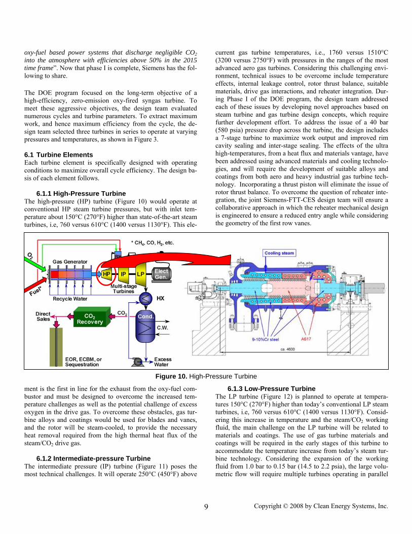
urbine he high-pressure (HP) turbine (Figure 10) would operate at onv res, but with inlet tem-
ment is the first in line for the exhaust from the oxy-fuel com-bustor and must be designed to overcome the increased tem-
te-pressure Turbine he intermediate pressure (IP) turbine (Figure 11) poses the ost (450°F) above
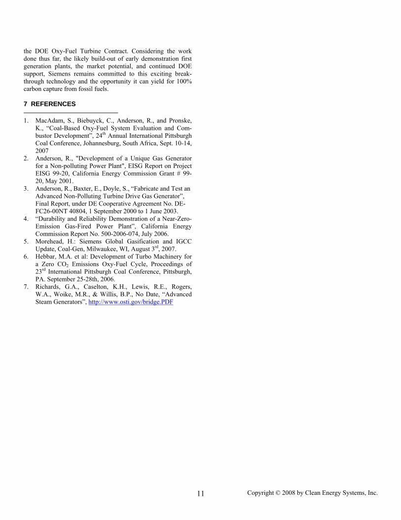
6.1.3 Low-Pressure Turbine The LP turbine (Figure 12) is planned to operate at tempera-
re ’s conventional LP steam
hmeet these aggressive objectives, the design team evaluated numerous cycles and turbine parameters. To extract maximum work, and hence maximum efficiency from the cycle, the de-sign team selected three turbines in series to operate at varying pressures and temperatures, as shown in Figure 3. 6.1 Turbine Elements Econditions to maximize ovesis of each element follows. 6.1.1 High-Pressure TTc entional HP steam turbine pressuperature about 150°C (270°F) higher than state-of-the-art steam turbines, i.e, 760 versus 610°C (1400 versus 1130°F). This ele-
perature challenges as well as the potential challenge of excess oxygen in the drive gas. To overcome these obstacles, gas tur-bine alloys and coatings would be used for blades and vanes, and the rotor will be steam-cooled, to provide the necessary heat removal required from the high thermal heat flux of the steam/CO2 drive gas. 6.1.2 IntermediaTm technical challenges. It will operate 250°C
current gas turbine temperatures, i.e., 1760 versus 1510°C (3200 versus 2750°F) with pressures in the ranges of the most advanced aero gas turbines. Considering this challenging envi-ronment, technical issues to be overcome include temperature effects, internal leakage control, rotor thrust balance, suitable materials, drive gas interactions, and reheater integration. Dur-ing Phase I of the DOE program, the design team addressed each of these issues by developing novel approaches based on steam turbine and gas turbine design concepts, which require further development effort. To address the issue of a 40 bar (580 psia) pressure drop across the turbine, the design includes a 7-stage turbine to maximize work output and improved rim cavity sealing and inter-stage sealing. The effects of the ultra high-temperatures, from a heat flux and materials vantage, have been addressed using advanced materials and cooling technolo-gies, and will require the development of suitable alloys and coatings from both aero and heavy industrial gas turbine tech-nology. Incorporating a thrust piston will eliminate the issue of rotor thrust balance. To overcome the question of reheater inte-gration, the joint Siemens-FTT-CES design team will ensure a collaborative approach in which the reheater mechanical design is engineered to ensure a reduced entry angle while considering the geometry of the first row vanes.
Figure 10. High-Pressure Turbine
tu s 150°C (270°F) higher than todayturbines, i.e, 760 versus 610°C (1400 versus 1130°F). Consid-ering this increase in temperature and the steam/CO2 working fluid, the main challenge on the LP turbine will be related to materials and coatings. The use of gas turbine materials and coatings will be required in the early stages of this turbine to accommodate the temperature increase from today’s steam tur-bine technology. Considering the expansion of the working fluid from 1.0 bar to 0.15 bar (14.5 to 2.2 psia), the large volu-metric flow will require multiple turbines operating in parallel
Copyright © 2008 by Clean Energy Systems, Inc. 9
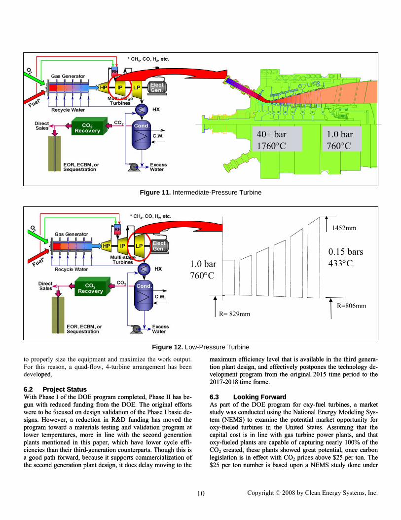
1.0 bar 760°C
40+ bar 1760°C
Figure 11. Intermediate-Pressure Turbine
1452mm
R=806mm R= 829mm
1.0 bar 760°C
0.15 bars 433°C
Figure 12. Low-Pressure Turbine
to properly size the equipment and maximize the work output. For this reason, a quad-flow, 4-turbine arrangement has been developed. 6.2 Proj
oped. 6.2 Project Status
ith Phase I of the DOE program completed, Phase II has be-g from the DOE. The original efforts
ard part of the DOE program for oxy-fuel turbines, a market
ional Energy Modeling Sys-
ect Status ith Phase I of the DOE program completed, Phase II has be-
g from the DOE. The original efforts ard
part of the DOE program for oxy-fuel turbines, a market ional Energy Modeling Sys-
WWgun with reduced fundingun with reduced fundinwere to be focused on design validation of the Phase I basic de-signs. However, a reduction in R&D funding has moved the program toward a materials testing and validation program at lower temperatures, more in line with the second generation plants mentioned in this paper, which have lower cycle effi-ciencies than their third-generation counterparts. Though this is a good path forward, because it supports commercialization of the second generation plant design, it does delay moving to the
maximum efficiency level that is available in the third genera-tion plant design, and effectively postpones the technology de-velopment program from the original 2015 time period to the 2017-2018 time frame. 6.3 Looking Forw
were to be focused on design validation of the Phase I basic de-signs. However, a reduction in R&D funding has moved the program toward a materials testing and validation program at lower temperatures, more in line with the second generation plants mentioned in this paper, which have lower cycle effi-ciencies than their third-generation counterparts. Though this is a good path forward, because it supports commercialization of the second generation plant design, it does delay moving to the
maximum efficiency level that is available in the third genera-tion plant design, and effectively postpones the technology de-velopment program from the original 2015 time period to the 2017-2018 time frame. 6.3 Looking ForwAs As study was conducted using the Natstudy was conducted using the Nattem (NEMS) to examine the potential market opportunity for oxy-fueled turbines in the United States. Assuming that the capital cost is in line with gas turbine power plants, and that oxy-fueled plants are capable of capturing nearly 100% of the CO2 created, these plants showed great potential, once carbon legislation is in effect with CO2 prices above $25 per ton. The $25 per ton number is based upon a NEMS study done under
tem (NEMS) to examine the potential market opportunity for oxy-fueled turbines in the United States. Assuming that the capital cost is in line with gas turbine power plants, and that oxy-fueled plants are capable of capturing nearly 100% of the CO2 created, these plants showed great potential, once carbon legislation is in effect with CO2 prices above $25 per ton. The $25 per ton number is based upon a NEMS study done under
Copyright © 2008 by Clean Energy Systems, Inc. 10
the DOE Oxy-Fuel Turbine Contract. Considering the work done thus far, the likely build-out of early demonstration first generation plants, the market potential, and continued DOE support, Siemens remains committed to this exciting break-through technology and the opportunity it can yield for 100% carbon capture from fossil fuels. 7 REFERENCES
iebuyck, C., Anderson, R., and Pronske, K., “Coal-Based Oxy-Fuel System Evaluation and Com-
2. on-polluting Power Plant", EISG Report on Project
3. Polluting Turbine Drive Gas Generator”,
4. -
5. 7.
s of
7. B.P., No Date, “Advanced
1. MacAdam, S., B
bustor Development”, 24th Annual International Pittsburgh Coal Conference, Johannesburg, South Africa, Sept. 10-14, 2007 Anderson, R., "Development of a Unique Gas Generator for a NEISG 99-20, California Energy Commission Grant # 99-20, May 2001. Anderson, R., Baxter, E., Doyle, S., “Fabricate and Test an Advanced Non-Final Report, under DE Cooperative Agreement No. DE-FC26-00NT 40804, 1 September 2000 to 1 June 2003. “Durability and Reliability Demonstration of a Near-ZeroEmission Gas-Fired Power Plant”, California Energy Commission Report No. 500-2006-074, July 2006. Morehead, H.: Siemens Global Gasification and IGCC Update, Coal-Gen, Milwaukee, WI, August 3rd, 200
6. Hebbar, M.A. et al: Development of Turbo Machinery for a Zero CO2 Emissions Oxy-Fuel Cycle, Proceeding23rd International Pittsburgh Coal Conference, Pittsburgh, PA. September 25-28th, 2006. Richards, G.A., Caselton, K.H., Lewis, R.E., Rogers, W.A., Woike, M.R., & Willis, Steam Generators”, http://www.osti.gov/bridge.PDF
Copyright © 2008 by Clean Energy Systems, Inc. 11