Embed Size (px)
Citation preview

*Corresponding author’s e-mail: [email protected]
Adaptability and Countermeasures of HVDC line protection under the UHVDC system with multiple receiving ends
Zhengguang Chen 1*, Xingguo Wang1, Shuyang Wang1 and Hong Cao1
1 China Electric Power Research Institute, Beijing, 100192, China
Abstract. In UHVDC transmission system, the inverter station is located in different geographical locations, and there are two sections of lines in single pole of HVDC system, which brings challenges to the traditional closed line protection. In this paper, firstly, the structural characteristics of series connection mode and the output characteristics of each converter in case of line fault are analysed, and the adaptability of conventional line protection in series multiple receiving ends system is studied. According to the characteristics of UHVDC system with multiple receiving ends in series connection mode, a hierarchical protection strategy is proposed and verified in PSCAD model.
1 Introduction
Line commutated converter based HVDC system has the prominent advantages in large capacity power transmission, and it is still the preferred solution in long-distance bulk power transmission [1-3]. Multi terminal direct current transmission (MTDC) project is a HVDC transmission system composed of three or more converter stations and their DC transmission lines. Up until now, there are several MTDC systems applied Line Commutated Converter technology under operation, Sardinia-Corsica-mainland Italy MTDC system, New England- Hydro Quebec MTDC system, Canada Nelson River four-terminal DC transmission system, Pacific Intertie HVDC, etc.[4-7]. Yunnan-Guizhou interconnected project is the first ± 500kV DC transmission project in China, which is constructed by China Southern Power Grid. To change two-terminal HVDC into three-terminal, the project builds a new Luquan converter station in Yunnan through the construction of DC lines connecting the built Gui-Guang HVDC system. It finally forms a three-terminal UHVDC transmission across Yunnan, Guizhou and Guangdong.
The advantages of UHVDC system with multi-receiving terminal are listed as below: the construction cost is reduced due to less DC line construction; improving the line utilization; reducing the impact of DC blocking on the receiving end grid with sharing one supply resource; each receiving end being able to adjust the power distribution and realize the optimal allocation of sending end resources. On the other hand, when HVDC system is constructed with multiple receiving ends, the line configuration has changed greatly, the closed characteristics of the conventional end-to-end HVDC system have been broken up, the line fault characteristics are different and the original line
protection principle can’t be fully applied. Other than that, as a single-terminal protection, it is difficult for traveling wave protection to determine the fault location. In the meantime, there are still risks of wrong or refusal operation for line protection during line faults. Therefore, it is highly necessary to analyse the suitable line protection strategies for multi-receiving ends HVDC system.
This paper analyses the topology of UHVDC system with multiple series receiving ends, and the characteristics of DC line faults. The corresponding simulation model is established in PSCAD. Next, the adaptability of the original DC line protection in new connection mode is analysed, according to the special requirements of this series connection, a novel protection scheme is proposed.
2 The UHVDC system with multiple receiving ends in series connection mode
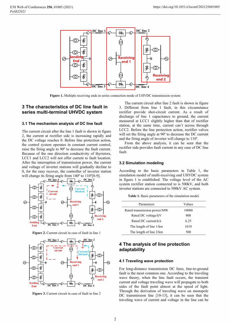
The series connection mode is shown in figure 1, the sending end of it is constructed as the same as conventional UHVDC system, the high-voltage and low-voltage valve at the receiving ends are connected with DC line, and each of them constitutes a different converter station independently. The DC line fault relevance is fairly high due to the series current. In the series connection mode, each station at receiving end has only one 12-pluse valve, which makes the full use of receiving ends’ capacity and reduce the construction cost. Compared to parallel connection mode, series mode has an edge in technical economy. Thus, this paper takes the series connection mode as main research subject.
E3S Web of Conferences 256, 01005 (2021)PoSEI2021
https://doi.org/10.1051/e3sconf/202125601005
© The Authors, published by EDP Sciences. This is an open access article distributed under the terms of the Creative Commons Attribution License 4.0 (http://creativecommons.org/licenses/by/4.0/).
Sending End
Receiving end 1
DC line 1
Receiving end 2
DC line 2
DC line 3 DC line 4
Figure 1. Multiple receiving ends in series connection mode of UHVDC transmission system
3 The characteristics of DC line fault in series multi-terminal UHVDC system
3.1 The mechanism analysis of DC line fault
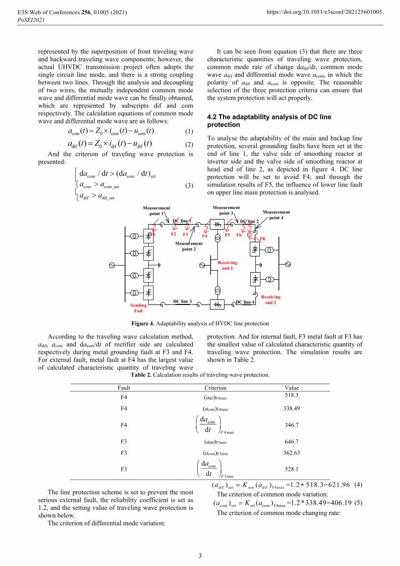
The current circuit after the line 1 fault is shown in figure 2, the current at rectifier side is increasing rapidly and the DC voltage reaches 0. Before line protection action, the control system operates in constant current control, raise the firing angle to 90º to decrease the fault current. Because of the one direction conductivity of thyristors, LCC1 and LCC2 will not offer current to fault location. After the interruption of transmission power, the current and voltage of inverter stations will gradually decline to 0, for the easy recover, the controller of inverter station will change its firing angle from 140º to 110º[8-9].
Sending End
Receiving end 1
DC line 1
Receiving end 2
DC line 2
DC line 3 DC line 4
Current circuit
Current blocked
Figure 2. Current circuit in case of fault in line 1
Sending End
Receiving end 1
DC line 1
Receiving end 2
DC line 2
DC line 3 DC line 4
Current circuit Current
blocked
Figure 3. Current circuit in case of fault in line 2
The current circuit after line 2 fault is shown in figure 3. Different from line 1 fault, in this circumstance rectifier provide shot-circuit current. As a result of discharge of line 1 capacitance to ground, the current measured at LCC1 slightly higher than that of rectifier station, at the same time, current can’t across through LCC2. Before the line protection action, rectifier valves will set the firing angle at 90º to decrease the DC current and the firing angle of inverter will change to 110º.
From the above analysis, it can be seen that the rectifier side provides fault current in any case of DC line fault.
3.2 Simulation modeling
According to the basic parameters in Table 1, the simulation model of multi-receiving end UHVDC system in figure 1 is established. The voltage level of the AC system rectifier station connected to is 500kV, and both inverter stations are connected to 500kV AC system.
Table 1. Basic parameters of the simulation model.
Parameters Values
Rated transmission power/MW 10000
Rated DC voltage/kV 800
Rated DC current/kA 6.25
The length of line 1/km 1618
The length of line 2/km 500
4 The analysis of line protection adaptability
4.1 Traveling wave protection
For long-distance transmission DC lines, line-to-ground fault is the most common one. According to the traveling wave theory, when the line fault occurs, the transient current and voltage traveling wave will propagate to both sides of the fault point almost at the speed of light. Through the derivation of traveling wave on monopole DC transmission line [10-13], it can be seen that the traveling wave of current and voltage in the line can be
E3S Web of Conferences 256, 01005 (2021)PoSEI2021
https://doi.org/10.1051/e3sconf/202125601005
2
represented by the superposition of front traveling wave and backward traveling wave components; however, the actual UHVDC transmission project often adopts the single circuit line mode, and there is a strong coupling between two lines. Through the analysis and decoupling of two wires, the mutually independent common mode wave and differential mode wave can be finally obtained, which are represented by subscripts dif and com respectively. The calculation equations of common mode wave and differential mode wave are as follows:
com 0 com com( ) ( ) ( )a t Z i t u t (1)
dif 0 dif dif( ) ( ) ( )a t Z i t u t (2)
And the criterion of traveling wave protection is presented:
com com set
com com_set
dif dif_set
d / d (d / d )a t a ta a
a a
(3)
It can be seen from equation (3) that there are three characteristic quantities of traveling wave protection, common mode rate of change dadif/dt, common mode wave adif and differential mode wave acom, in which the polarity of adif and acom is opposite. The reasonable selection of the three protection criteria can ensure that the system protection will act properly.
4.2 The adaptability analysis of DC line protection
To analyse the adaptability of the main and backup line protection, several grounding faults have been set at the end of line 1, the valve side of smoothing reactor at inverter side and the valve side of smoothing reactor at head end of line 2, as depicted in figure 4. DC line protection will be set to avoid F4, and through the simulation results of F5, the influence of lower line fault on upper line main protection is analysed.
DC line 1 DC line 2
F2F1 F4
DC line 3 DC line 4
F6F8
Measurement point 2
F3 F5 F7
Sending End
Receiving end 1
Receiving end 2
Measurement point 1
Measurement point 3 Measurement
point 4
Figure 4. Adaptability analysis of HVDC line protection
According to the traveling wave calculation method, adif, acom and dacom/dt of rectifier side are calculated respectively during metal grounding fault at F3 and F4. For external fault, metal fault at F4 has the largest value of calculated characteristic quantity of traveling wave
protection. And for internal fault, F3 metal fault at F3 has the smallest value of calculated characteristic quantity of traveling wave protection. The simulation results are shown in Table 2.
Table 2. Calculation results of traveling wave protection.
Fault Criterion Value
F4 (adif)F4max 518.3
F4 (acom)F4max 338.49
F4 com
4 max
d
d F
a
t
346.7
F3 (adif)F3min 646.7
F3 (acom)F3min 362.63
F3 com
3min
d
d F
a
t
528.1
The line protection scheme is set to prevent the most serious external fault, the reliability coefficient is set as 1.2, and the setting value of traveling wave protection is shown below.
The criterion of differential mode variation:
dif set sen dif F4max( ) ( ) =1.2 518.3=621.96a K a (4)
The criterion of common mode variation:
com set rel com F4max( ) ( ) =1.2*338.49=406.19a K a (5)
The criterion of common mode changing rate:
E3S Web of Conferences 256, 01005 (2021)PoSEI2021
https://doi.org/10.1051/e3sconf/202125601005
3

com set rel com F4max(d d ) (d d ) =1.2 346.7=416.04a t K a t
(6)
The action characteristics of criterions are drawn in figure 5-7.
4.90 4.95 5.00 5.05 5.10-180
40
260
480
700621.96
a dif/k
V
t/s 4.90 4.95 5.00 5.05 5.10
-160
60
280
500
720
621.96
a dif/k
V
t/s 4.90 4.95 5.00 5.05 5.10
-200
30
260
490
720
621.96
a dif/k
V
t/s a) Fault F3 b) Fault F4 c) Fault F5
Figure 5. Action characteristics of differential mode variation criterion under different fault points
4.90 4.95 5.00 5.05 5.10-180
-10
160
330
500
406.19
a com
/kV
t/s 4.90 4.95 5.00 5.05 5.10
-180
-10
160
330
500
406.19
a com
/kV
t/s 4.90 4.95 5.00 5.05 5.10
-150
10
170
330
490
406.19
a com
/kV
t/s a) Fault F3 b) Fault F4 c) Fault F5
Figure 6. Action characteristics of common mode variation criterion under different fault points
4.90 4.95 5.00 5.05 5.10-380
-140
100
340
580
416.04
daco
m/d
t (k
V/m
s)
t/s4.90 4.95 5.00 5.05 5.10
-300
-90
120
330
540
416.04
daco
m/d
t (k
V/m
s)
t/s 4.90 4.95 5.00 5.05 5.10
-340
-100
140
380
620
416.04
daco
m/d
t (k
V/m
s)
t/s a) Fault F3 b) Fault F4 c) Fault F5
Figure 7. Action characteristics of common mode rate of change criterion under different fault points
It can be seen from the figure above that the traveling wave protection can operate correctly in case of fault in the internal area; it is reliable and does not operate in case of fault in the lower line.
5 Hierarchical protection strategy
The traveling wave line protection is set at line 2 as well. In order to realize the continuous operation of high-end valve under the permanent fault of DC line 2, the positive pole being taken as an example. The disconnector CB1 is configured near the inverter station LCC1, the grounding electrode GND1 is constructed at LCC1 and the isolating switch CB3 is configured to the grounding electrode. In normal operation, CB1 is closed and CB3 is open. The line pattern is shown in figure 8.
E3S Web of Conferences 256, 01005 (2021)PoSEI2021
https://doi.org/10.1051/e3sconf/202125601005
4

DC line 1 DC line 2
DC line 3
CB1
CB3
CB4
CB2DC line 4Sending
End
Receiving end 1
Receiving end 2
Figure 8. Action characteristics under different fault points
When transient fault occurs at line 2, the inverter station LCC1 sends protection action signal to the rectifier station, and the rectifier station restarts after forced phase shifting. When the permanent fault occurs at line 2, after failed restart, the phase is shifted again. After detecting that the current of line 2 crosses zero, the DC switch CB1 is disconnected and the DC switch CB3 is closed. The fault pole operates at half voltage and the non-fault pole operates at full voltage.
6 Conclusion
This paper studies the line protection strategy suitable for the UHVDC with series receiving ends, and builds the electromagnetic transient simulation model in PSCAD/EMTDC. Next, the adaptability of the current protection is analysed, and the corresponding solutions is carried out. The conclusions are as follows.
1) When the fault occurs at line 2, the rectifier station provides the fault current to the fault location through the high-end inverter valve.
2) At present, traveling wave protection is able to fit in the novel connection mode.
3) A hierarchical protection action strategy is proposed. The protection can act rapidly to isolate the fault in case of line 2 faults and can guarantee half of the power transmission even under permanent line 2 failure.
Acknowledgments
This work was supported in part by Funding for science and technology projects of State Grid Corporation of China (No. 5110-201955378A-0-0-00).
References
1. LIANG Xuming, ZHANG Ping, CHANG Yong. (2010) Recent Advances in high-voltage direct-current power transmission and its developing potential. Power System Technology, 4:1-9.
2. Zhang Baohui, Zhang Song et al. (2010) Research on transient-based protection for HVDC lines. Power System Protection and Control, 15:18-23.
3. Song Guobing, Chu Xu et al. (2013) A whole-line quick action protection principle for HVDC
transmission lines using one-end current of DC filters. Proceedings of the CSEE,22:120-126.
4. Yang Yayu, Tai Nengling, Liu Jian et al. (2015) A pilot protection for HVDC transmission based on boundary energy. Proceedings of the CSEE, 22: 5757-5767.
5. Huang Zijun, Chen Yunping. (2005) Non-communication fault locating of transmission line based on wavelet modulus maxima. Electric Power Automation Equipment, 2:10-15.
6. Jiang Chongxue, Lu Yu, et al. (2017) Analysis of Traveling Wave Protection and Study on Coordination Strategy in Flexible DC Grid. Distribution & Utilization, 3:51-57.
7. Dong Xinzhou, Tang Lanxi, et al. (2018) Configuration Scheme of Transmission Line Protection for Flexible HVDC Grid. Power System Technology. 6: 1753-176.
8. QahramanB, GoleA. (2005) A VSC based series hybrid converter for HVDC transmission. IEEE CCECE/CCGEI. Saskatoon: IEEE, 2005: 458-461.
9. Zhang Shuoting, Li Yalong, Liu Bo, et al. (2017) HVDC converter transformer saturation in hybrid system caused by coupled transmission lines. IEEE Transactions on Power Electronics, 7: 4099-4110.
10. Li Rui, Grain Philip Adam, Derrick Holliday, et al. (2015) Hybrid cascaded modular multilevel converter with DC fault ride-through capability for the HVDC transmission system. IEEE Transactions on Power Delivery. 4:1853-1863.
11. QahramanB, GoleAM, FernandoIT, et al. (2006) Hybrid HVDC converters and their impact on power system dynamic performance. IEEE Transactions on Power Delivery, 7:1042-1048.
12. GuoChunyi, Zhao Chengyong, Allan Montanari, et al. (2012) Investigation of hybrid bipolar HVDC system performances. Proceedings of the CSEE, 10: 98-106.
13. Dong Xinzhou, Tang Lanxi, Shi Shenxing, et al. (2018) Configuration scheme of transmission line protection for flexible HVDC grid. Power System Technology, 6: 1753-1761.
14. Zhang Baohui, Power system relay protection (2015) CEPP, Beijing.
E3S Web of Conferences 256, 01005 (2021)PoSEI2021
https://doi.org/10.1051/e3sconf/202125601005
5
15. Hong Chao, Shi Bonian, et al. (2017) Fault Characteristics and control & protection strategy of
three-terminal LCC-MMC hybrid HVDC System. Electric Power Construction 8: 73-80.
E3S Web of Conferences 256, 01005 (2021)PoSEI2021
https://doi.org/10.1051/e3sconf/202125601005
6