Embed Size (px)
Citation preview
ADAPT | 2
KIT CONTENTS
(1) Mounting Hardware
(2) Black Powder Coated L-Shape Brackets
(1) Dash Controller
(1) Under Dash Module
(1) Wiring Harness
SOLD SEPARATELY
(1) Mounting Brackets
(1) Under Dash Module Harness
Underside Low-Profile Stealth Mounts Light Covers GPS Module
ADAPT | 3
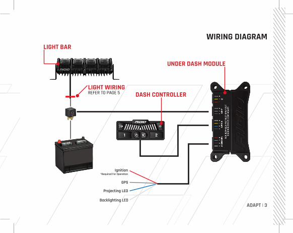
Ignition*Required For Operation
GPS
Projecting LED
Backlighting LED
BT
WIRING DIAGRAMLIGHT BAR
LIGHT WIRINGREFER TO PAGE 5 DASH CONTROLLER
UNDER DASH MODULE
ADAPT | 4
MODE 1FLOOD
DRIVING
SPOT
MODE 2FLOOD
DRIVING
SPOT
MODE 3FLOOD
DRIVING
SPOT
MODE 4FLOOD
DRIVING
SPOT
GPS TRACKING
8 MODES
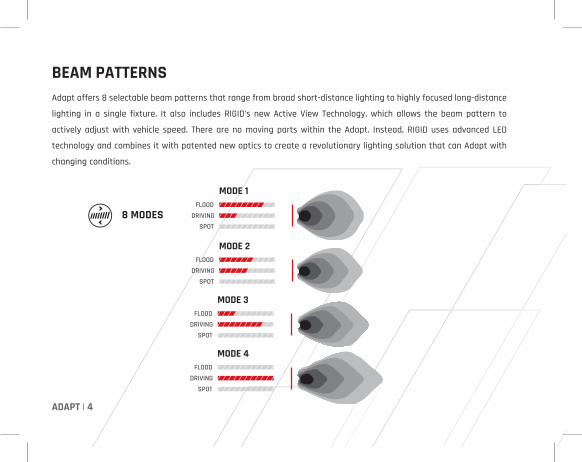
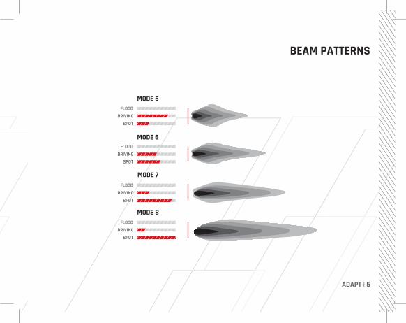
Adapt offers 8 selectable beam patterns that range from broad short-distance lighting to highly focused long-distance
lighting in a single fixture. It also includes RIGID’s new Active View Technology, which allows the beam pattern to
actively adjust with vehicle speed. There are no moving parts within the Adapt. Instead, RIGID uses advanced LED
technology and combines it with patented new optics to create a revolutionary lighting solution that can Adapt with
changing conditions.
BEAM PATTERNS
ADAPT | 5
MODE 5FLOOD
DRIVING
SPOT
MODE 6FLOOD
DRIVING
SPOT
MODE 7FLOOD
DRIVING
SPOT
MODE 8FLOOD
DRIVING
SPOT
BEAM PATTERNS
ADAPT | 6
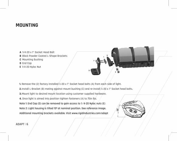
1. Remove the (2) factory installed 1⁄4-20 x 1” Socket head bolts (A) from each side of light.
2. Install L-Bracket (B) mating against mount bushing (C) and re-install 1⁄4-20 x 1” Socket head bolts.
3. Mount light to desired mount location using customer supplied hardware.
4. Once light is aimed into position tighten fasteners (A) to 75in lbs.
Note 1: End Cap (D) can be removed to gain access to 1 ⁄ 4-20 Nyloc nuts (E)
Note 2: Light housing is tilted 15º at nominal position. See reference image.
Additional mounting brackets available. Visit www.rigidindustries.com/adapt
MOUNTING
A 1/4-20 x 1” Socket Head BoltB Black Powder Coated L-Shape BracketsC Mounting BushingD End CapE 1/4-20 Nyloc Nut
ADAPT | 7
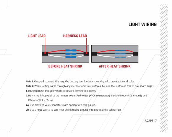
Note 1: Always disconnect the negative battery terminal when working with any electrical circuits.
Note 2: When routing wires through any metal or abrasive surfaces, be sure the surface is free of any sharp edges.
1. Route harness through vehicle to desired termination points.
2. Match the light pigtail to the harness colors: Red to Red (+VDC main power), Black to Black (-VDC Ground), and
White to White (Data)
2a. Use provided wire connectors with appropriate wire gauge.
2b. Use a heat source to seal heat shrink tubing around wire and seal the connection.
LIGHT WIRING
LIGHT LEAD HARNESS LEAD
BEFORE HEAT SHRINK AFTER HEAT SHRINK
ADAPT | 8
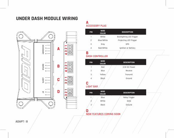
UNDER DASH MODULE WIRING
A
D
C
B
ACCESSORYSW
ITCHLIGHTS
BT1
23
41
23
41
23
12
3
AACCESSORY PLUG
PIN WIRE COLOR DESCRIPTION
1 White Backlighting LED Trigger
2 Blue/White Projecting LED Trigger
3 Gray GPS
4 Red/White Ignition or Battery
BDASH CONTROLLER
PIN WIRE COLOR DESCRIPTION
1 Red 3.3V DC Power
2 Blue Receive
3 Yellow Transmit
4 Black Ground
CLIGHT BAR
PIN WIRE COLOR DESCRIPTION
1 Blue Relay Trigger
2 White Data
3 Black Ground
DNEW FEATURES COMING SOON
ADAPT | 9
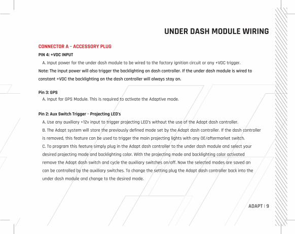
UNDER DASH MODULE WIRING
CONNECTOR A – ACCESSORY PLUGPIN 4: +VDC INPUT
A. Input power for the under dash module to be wired to the factory ignition circuit or any +VDC trigger.
Note: The input power will also trigger the backlighting on dash controller. If the under dash module is wired to
constant +VDC the backlighting on the dash controller will always stay on.
Pin 3: GPS A. Input for GPS Module. This is required to activate the Adaptive mode.
Pin 2: Aux Switch Trigger – Projecting LED’s
A. Use any auxiliary +12v input to trigger projecting LED’s without the use of the Adapt dash controller.
B. The Adapt system will store the previously defined mode set by the Adapt dash controller. If the dash controller
is removed, this feature can be used to trigger the main projecting lights with any OE/aftermarket switch.
C. To program this feature simply plug in the Adapt dash controller to the under dash module and select your
desired projecting mode and backlighting color. With the projecting mode and backlighting color activated
remove the Adapt dash switch and cycle the auxiliary switches on/off. Now the selected modes are saved an
can be controlled by the auxiliary switches. To change the setting plug the Adapt dash controller back into the
under dash module and change to the desired mode.
ADAPT | 10
UNDER DASH MODULE WIRING
Pin 1: Aux Switch Trigger - Backlighting LED
A. Use any auxiliary +12v input to trigger the backlighting LED’s without the use of the Adapt dash controller.
B. The Adapt system will store the previously defined backlighting color set by the Adapt dash switch. If the Adapt
dash controller is removed this feature can be used to trigger the backlighting LED’s with any OE/aftermarket switch.
C. To program this feature simply plug in the Adapt dash controller to the under dash module and select your desired
projecting mode and backlighting color. With the projecting mode and backlighting color activated remove the Adapt
dash controller and cycle the auxiliary switches on/off. Now the selected modes are saved and can be controlled by
the auxiliary switches. To change the setting plug the Adapt dash controller back into the under dash module and
change to the desired mode.
D. Once all connections are final, attach the battery leads to the vehicle’s battery.
Note: Both primary projecting mode and back lighting color must be in the on position before removing the Adapt Dash
controller in order for the auxiliary switches to function properly.
Note: The auxiliary switch trigger cannot change backlighting colors, it will only trigger the previously defined back
lighting color set by the Adapt dash controller
ADAPT | 11
UNDER DASH MODULE WIRING
CONNECTOR B – DASH CONTROLLERThe supplied Adapt dash controller is pre terminated by RIGID to plug directly into the Adapt Under Dash
Module. Ensure the dash controller cable is secured and does not have tension once installed.
CONNECTOR C – LIGHT BARThe Adapt Harness is pre terminated by RIGID to plug directly into the Adapt Under dash module. Ensure the harness is secured and does not have tension once installed.
CONNECTOR D – BLUETOOTH - COMING SOON
ADAPT | 12
E.
C. D.
A. B.
G. H.
F.
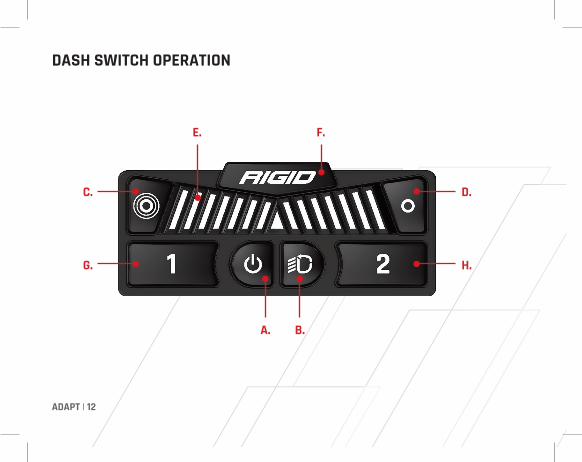
DASH SWITCH OPERATION
ADAPT | 13
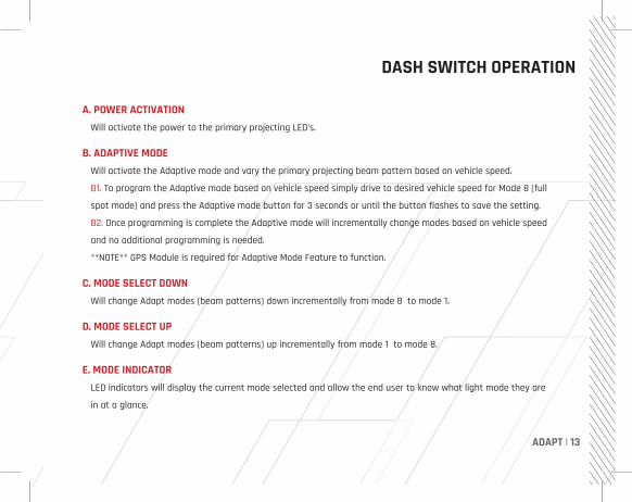
A. POWER ACTIVATION Will activate the power to the primary projecting LED’s.
B. ADAPTIVE MODE Will activate the Adaptive mode and vary the primary projecting beam pattern based on vehicle speed.
B1. To program the Adaptive mode based on vehicle speed simply drive to desired vehicle speed for Mode 8 (full
spot mode) and press the Adaptive mode button for 3 seconds or until the button flashes to save the setting.
B2. Once programming is complete the Adaptive mode will incrementally change modes based on vehicle speed
and no additional programming is needed.
**NOTE** GPS Module is required for Adaptive Mode Feature to function.
C. MODE SELECT DOWN Will change Adapt modes (beam patterns) down incrementally from mode 8 to mode 1.
D. MODE SELECT UP Will change Adapt modes (beam patterns) up incrementally from mode 1 to mode 8.
E. MODE INDICATOR LED indicators will display the current mode selected and allow the end user to know what light mode they are
in at a glance.
DASH SWITCH OPERATION
ADAPT | 14
DASH SWITCH OPERATION
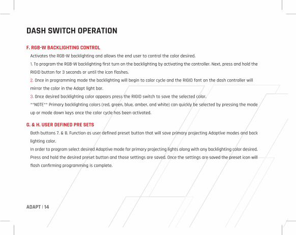
F. RGB-W BACKLIGHTING CONTROL Activates the RGB-W backlighting and allows the end user to control the color desired.
1. To program the RGB-W backlighting first turn on the backlighting by activating the controller. Next, press and hold the
RIGID button for 3 seconds or until the icon flashes.
2. Once in programming mode the backlighting will begin to color cycle and the RIGID font on the dash controller will
mirror the color in the Adapt light bar.
3. Once desired backlighting color appears press the RIGID switch to save the selected color.
**NOTE** Primary backlighting colors (red, green, blue, amber, and white) can quickly be selected by pressing the mode
up or mode down keys once the color cycle has been activated.
G. & H. USER DEFINED PRE SETS Both buttons 7. & 8. Function as user defined preset button that will save primary projecting Adaptive modes and back
lighting color.
In order to program select desired Adaptive mode for primary projecting lights along with any backlighting color desired.
Press and hold the desired preset button and those settings are saved. Once the settings are saved the preset icon will
flash confirming programming is complete.
ADAPT | 15
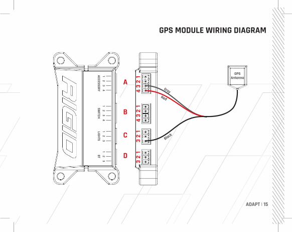
GPS MODULE WIRING DIAGRAM
A
D
C
B
GPSAntenna
Gray
ACCESSORYSW
ITCHLIGHTS
BT1
23
41
23
41
23
12
3
ADAPT | 16
This GPS module is required for the Adaptive Mode feature in the RIGID Adapt light bar. Once this unit is installed, the RIGID
Adapt will use the GPS signal to automatically change modes based on vehicle speed.
MOUNTING 1. Find the desired location to mount the GPS interface module that is protected against heat and water submersion.
2. The mounting orientation is not critical to the function of the unit so it can be easily mounted on a vertical or
horizontal surface using mounting screws, zip ties, or tape.
CABLE ROUTING 1. The GPS antenna has a magnetic base, so it will securely hold in place on any metal surface.
2. The GPS antenna needs to have line of site to the Satellite’s in the sky. It is recommended to be placed on the roof
of the vehicle.
3. When routing wire cable through any metal surface, be sure it is free of any sharp edges and protected using wire
sheathing or a grommet.
WIRING - REFER TO PAGE 15 1. Connect the GPS antenna to the interface module by screwing the SMA connector on the antenna cable to the
mating connector on the module. Be careful not to over torque this connection if using a wrench.
2. The red wire from the GPS module will share pin 4 on connector A on the Adapt under dash module. This wire will
provide ignition power to the GPS unit.
GPS MODULE OPERATION
ADAPT | 17
3. The Black Wire from the GPS module will share pin 3 connector C on the Adapt under dash module. This will provide
chassis ground to the GPS unit.
4. The gray wire from the GPS module will go directly into pin 3 connector A on the Adapt under dash module. This will
provide the GPS signal to the Adapt unit.
OPERATION 1. Once the GPS unit is mounted and all wiring is connected properly, you are ready to test the unit.
2. Turn vehicle on. This will provide power to the GPS and Adapt system.
3. It can take up to 2 minutes for the GPS to find a satellite before the unit will provide a signal to the Adapt under
dash module.
4. Activate the Adaptive mode by pressing the Adapt Icon on the Adapt dash controller. Adaptive mode will default to
Mode 1.
5. The Adapt mode is user adjustable so you can calibrate the top intended speed. To calibrate the Adapt Mode, safely
drive at the top speed where spot mode will be desirable. While remaining at this speed, press and hold the Adaptive
Mode button on the Adapt dash controller until the Adapt Mode button icon flashes red. This indicates that the top
speed was saved.
6. The Adapt system will now operate in mode 8 based on the top speed selected and automatically step down
incrementally from mode 8 to mode 1 as your vehicle speed is reduced. Simply turn off the Adapt mode by pressing
the Adapt icon on the Adapt dash controller.
GPS MODULE OPERATION

ADAPT | 18
NOTES

ADAPT | 19
NOTES

WARRANTY INFORMATIONFor warranty information, visit www.rigidindustries.com/about/warranty
779 N Colorado St, Gilbert, AZ 85233 • 855-760-5337www.rigidindustries.com
Adapt, RIGID, and Rigid Industries are registered and/or common law marks owned by JST Performance, LLC,a Delaware limited liability company d/b/a Rigid Industries.
10-12173-D