Embed Size (px)
Citation preview
Adafruit Powerboost 1000 BasicCreated by lady ada
Last updated on 2017-06-01 04:09:26 PM UTC

2378999
11111111
Guide Contents
Guide ContentsOverviewPinoutsPower PinsControl Pins(http://adafru.it/dLZ)LEDsBattery and USB connectionDownloadsDatasheets & FilesSchematicsPCB Print
© Adafruit Industries https://learn.adafruit.com/adafruit-powerboost-1000-basic Page 2 of 12

Overview
PowerBoost is the perfect power supply for your power-hungry portable project! This littleDC/DC boost converter module can run from 1.8V batteries or higher, and convert thatvoltage to 5.2V DC for running your 5V projects. With a beefy 4A DC/DC converter, it cangive you 1A+ from as low as 2V.
Like our popular 5V 1A USB wall adapter (http://adafru.it/duP), we tweaked the output to be5.2V instead of a straight-up 5.0V so that there's a little bit of 'headroom' long cables, highdraw, the addition of a diode on the output if you wish, etc. The 5.2V is safe for all 5V-powered electronics like Arduino, Raspberry Pi, or Beagle Bone while preventing ickybrown-outs during high current draw because of USB cable resistance.
© Adafruit Industries https://learn.adafruit.com/adafruit-powerboost-1000-basic Page 3 of 12
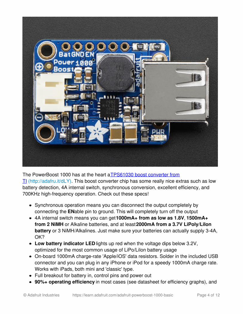
The PowerBoost 1000 has at the heart a TPS61030 boost converter fromTI (http://adafru.it/dLY). This boost converter chip has some really nice extras such as lowbattery detection, 4A internal switch, synchronous conversion, excellent efficiency, and700KHz high-frequency operation. Check out these specs!
Synchronous operation means you can disconnect the output completely byconnecting the ENable pin to ground. This will completely turn off the output4A internal switch means you can get 1000mA+ from as low as 1.8V, 1500mA+from 2 NiMH or Alkaline batteries, and at least 2000mA from a 3.7V LiPoly/LiIonbattery or 3 NiMH/Alkalines. Just make sure your batteries can actually supply 3-4A,OK?Low battery indicator LED lights up red when the voltage dips below 3.2V,optimized for the most common usage of LiPo/LiIon battery usageOn-board 1000mA charge-rate 'Apple/iOS' data resistors. Solder in the included USBconnector and you can plug in any iPhone or iPod for a speedy 1000mA charge rate.Works with iPads, both mini and 'classic' type.Full breakout for battery in, control pins and power out90%+ operating efficiency in most cases (see datasheet for efficiency graphs), and
© Adafruit Industries https://learn.adafruit.com/adafruit-powerboost-1000-basic Page 4 of 12

low quiescent current: 5mA when enabled and power LED is on, 20uA when disabled(power and low batt LED are off)
Great for powering your robot, Arduino project, single-board-computer such as RaspberryPi or BeagleBone! Each order comes with one fully assembled and tested PCB, a loose 2-PH JST jack, a 2-pin Terminal block and a loose USB A jack.
© Adafruit Industries https://learn.adafruit.com/adafruit-powerboost-1000-basic Page 5 of 12

If you are powering your project from USB, solder the USB A jack in (a 3-minute solderingtask). Then choose either JST for input (JST is often used for our LiIon batteries, but theconnector is only rated for 2A) or a terminal block.
If you would like to use another terminal block for output, pick up a 3.5mm 2pin blockhere (http://adafru.it/duR) and solder to the output spot where the USB jack would go. Ordon't solder any connectors in for a more compact power pack and go with 22AWG wiressoldered directly in.
© Adafruit Industries https://learn.adafruit.com/adafruit-powerboost-1000-basic Page 6 of 12

Pinouts
For many people, the PowerBoost can be used with just the power input and poweroutputs. However, we have a couple handy breakouts so lets get started!
© Adafruit Industries https://learn.adafruit.com/adafruit-powerboost-1000-basic Page 7 of 12
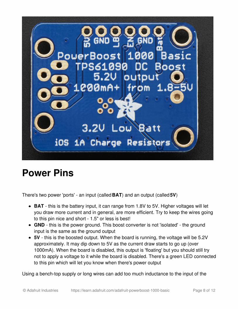
Power Pins
There's two power 'ports' - an input (called BAT) and an output (called 5V)
BAT - this is the battery input, it can range from 1.8V to 5V. Higher voltages will letyou draw more current and in general, are more efficient. Try to keep the wires goingto this pin nice and short - 1.5" or less is best!GND - this is the power ground. This boost converter is not 'isolated' - the groundinput is the same as the ground output5V - this is the boosted output. When the board is running, the voltage will be 5.2Vapproximately. It may dip down to 5V as the current draw starts to go up (over1000mA). When the board is disabled, this output is 'floating' but you should still trynot to apply a voltage to it while the board is disabled. There's a green LED connectedto this pin which will let you know when there's power output
Using a bench-top supply or long wires can add too much inductance to the input of the
© Adafruit Industries https://learn.adafruit.com/adafruit-powerboost-1000-basic Page 8 of 12

boost converter and destroy it! We really do recommend using Lipoly batteries with shortwires
Control PinsThere's two 'control' pins.
EN - this is the 'enable' pin. By default it is pulled 'high' to VBAT. To turn off thebooster, connect this pin to ground. The switch can be as small as you like, it is just asignal. Contrast this to an inline power switch which would have to be able to handleup to 4A of current! When the chip is disabled the output is completely disconnectedfrom the input.LBO - not a leveraged buy out! this is the Low Battery Output. By default it is pulledhigh to BAT but when the charger detects a low voltage (under 3.2V) the pin will dropdown to 0V. You can use this to signal when its time to shut down or alert the userthat the battery is low. There is also a red LED connected to this pin.
(http://adafru.it/dLZ)LEDsThere are two onboard LEDs. The Green LED sits next to the USB connector socket, andindicates the 5V output power state. The Red LED is next to the battery JST port andindicates when the battery voltage is below 3.2VDC
Battery and USB connectionYou can connect a battery to the breakout strip or to the input end. We do not solder on aJST connector because JST 2-PH are rated for 2A and the boost converter can suck upto 4A thru the contacts! If you're pretty sure that you won't be sourcing more than 2A, say ifyou're going to have 1A output and 3.7V LiPoly/LiIon input, you can go ahead and use aJST connector. All of Adafruit batteries come with JST cables that will plug in nicely. Watchthe polarity of the cable! the + and - markings next to the JST will let you know which wayis which.
If you aren't using a LiIon or if you are going to be drawing more than 2A from the input,then we suggest going with the 3.5mm terminal block, solder that where the JST would go.
On the output side, the USB connector can be soldered on to create a portable 'USB powerpack'. The two data lines on USB have resistor dividers that match Apple charger values sothat you can plug any iOS device in to charge. 99% of other phones, devices and tables are
© Adafruit Industries https://learn.adafruit.com/adafruit-powerboost-1000-basic Page 9 of 12

totally cool with these resistors as well. You can always short the D+ and D- lines if youhappen to have a phone that wants shorted data lines.
If you don't want a USB connector attached, there are two holes that are designed for a3.5mm spaced terminal block
© Adafruit Industries https://learn.adafruit.com/adafruit-powerboost-1000-basic Page 10 of 12

Downloads
Datasheets & FilesTPS61030 datasheet (http://adafru.it/dM0)(the DC/DC boost control chip used)EagleCAD PCB files on GitHub (http://adafru.it/pD1)Fritzing object in Adafruit Fritzing library (http://adafru.it/aP3)
Schematics
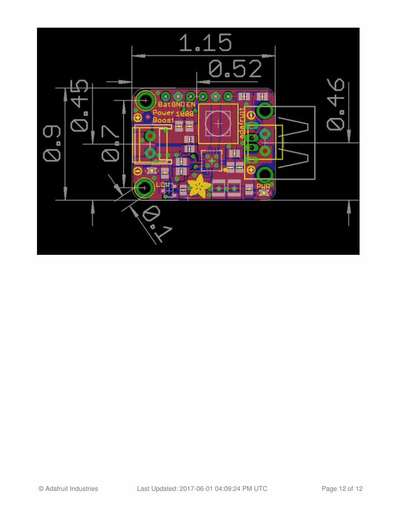
PCB PrintDimensions in Inches
© Adafruit Industries https://learn.adafruit.com/adafruit-powerboost-1000-basic Page 11 of 12
© Adafruit Industries Last Updated: 2017-06-01 04:09:24 PM UTC Page 12 of 12