Embed Size (px)
Citation preview

Adafruit Metro M0 Express - Designed for CircuitPythonCreated by lady ada
Last updated on 2017-06-19 10:35:09 PM UTC
2599
1011111112
12131314151516
17171920202122
2323242627
2929303032
Guide Contents
Guide ContentsOverviewPinoutsPower ConnectionsLogic pins
Top RowBottom RowRight sideAdditional analog inputs
SPI Flash and NeoPixelOther Pins!Debug Interface
SEGGER J-Link EDU - JTAG/SWD DebuggerSEGGER J-Link BASE - JTAG/SWD DebuggerJTAG (2x10 2.54mm) to SWD (2x5 1.27mm) Cable Adapter Board10-pin 2x5 Socket-Socket 1.27mm IDC (SWD) Cable - 150mm long
UF2 Bootloader DetailsEntering Bootloader ModeUsing the Mass Storage BootloaderUsing the BOSSA Bootloader
Windows 7 DriversVerifying Serial Port in Device ManagerRunning bossac on the command line
Updating the bootloaderGetting Rid of Windows Pop-upsMaking your own UF2Arduino IDE Setup
https://adafruit.github.io/arduino-board-index/package_adafruit_index.json
Using with Arduino IDEInstall SAMD SupportInstall Adafruit SAMDInstall Drivers (Windows 7 Only)Blink
© Adafruit Industries https://learn.adafruit.com/adafruit-metro-m0-express-designed-for-circuitpython
Page 2 of 54
32333334353535353637373737383839394141424344464647474949
5151515252
Sucessful UploadCompilation IssuesManually bootloadingUbuntu & Linux Issue FixAdapting Sketches to M0Analog ReferencesPin Outputs & PullupsSerial vs SerialUSBAnalogWrite / PWMMissing header filesBootloader LaunchingAligned Memory AccessFloating Point ConversionHow Much RAM Available?Storing data in FLASHUsing SPI FlashRead & Write CircuitPython FilesFormat Flash MemoryDatalogging ExampleReading and Printing FilesFull Usage ExampleMetro M0 HELP!CircuitPython SetupDownloadingFlashingFlashing UF2Flashing with BOSSAC
After flashing
CircuitPython Blinkycode.pyStatus LEDDebuggingLibraries
© Adafruit Industries https://learn.adafruit.com/adafruit-metro-m0-express-designed-for-circuitpython
Page 3 of 54

52535353
More infoDownloadsDatasheetsSchematic & Fabrication Print
© Adafruit Industries https://learn.adafruit.com/adafruit-metro-m0-express-designed-for-circuitpython
Page 4 of 54
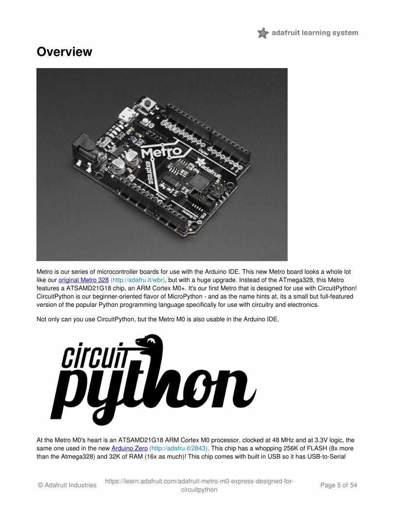
Overview
Metro is our series of microcontroller boards for use with the Arduino IDE. This new Metro board looks a whole lotlike our original Metro 328 (http://adafru.it/wbr), but with a huge upgrade. Instead of the ATmega328, this Metrofeatures a ATSAMD21G18 chip, an ARM Cortex M0+. It's our first Metro that is designed for use with CircuitPython!CircuitPython is our beginner-oriented flavor of MicroPython - and as the name hints at, its a small but full-featuredversion of the popular Python programming language specifically for use with circuitry and electronics.
Not only can you use CircuitPython, but the Metro M0 is also usable in the Arduino IDE.
At the Metro M0's heart is an ATSAMD21G18 ARM Cortex M0 processor, clocked at 48 MHz and at 3.3V logic, thesame one used in the new Arduino Zero (http://adafru.it/2843). This chip has a whopping 256K of FLASH (8x morethan the Atmega328) and 32K of RAM (16x as much)! This chip comes with built in USB so it has USB-to-Serial
© Adafruit Industries https://learn.adafruit.com/adafruit-metro-m0-express-designed-for-circuitpython
Page 5 of 54

program & debug capability built in with no need for an FTDI-like chip.
Power the METRO with 7-9V polarity protected DC or the micro USB connector to any 5V USB source. The2.1mm DC jack has an on/off switch next to it so you can turn off your setup easily. The METRO willautomagically switch between USB and DC.METRO has 25 GPIO pins, 12 of which are analog in, and one of which is a true analog out. There's ahardware SPI port, hardware I2C port and hardware UART. Logic level is 3.3VNative USB, there's no need for a hardware USB to Serial converter as the Metro M0 has built in USBsupport. When used to act like a serial device, the USB interface can be used by any computer to listen/senddata to the METRO, and can also be used to launch and update code via the bootloader. It can also act like akeyboard, mouse or MIDI device as well.Four indicator LEDs and one NeoPixel, on the front edge of the PCB, for easy debugging. One green powerLED, two RX/TX LEDs for data being sent over USB, and a red LED connected. Next to the reset button thereis an RGB NeoPixel that can be used for any purpose.2 MB SPI Flash storage chip is included on board. You can use the SPI Flash storage like a very tiny harddrive. When used in Circuit Python, the 2 MB flash acts as storage for all your scripts, libraries and files. Whenused in Arduino, you can read/write files to it, like a little datalogger or SD card, and then with our helperprogram, access the files over USB.Easy reprogramming, comes pre-loaded with the UF2 bootloader (http://adafru.it/wbC), which looks like aUSB key. Simply drag firmware on to program, no special tools or drivers needed! It can be used byMakeCode or Arduino IDE (in bossa compatibility)
© Adafruit Industries https://learn.adafruit.com/adafruit-metro-m0-express-designed-for-circuitpython
Page 6 of 54
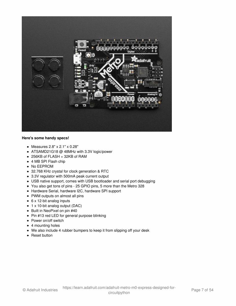
Here's some handy specs!
Measures 2.8" x 2.1" x 0.28"ATSAMD21G18 @ 48MHz with 3.3V logic/power256KB of FLASH + 32KB of RAM4 MB SPI Flash chipNo EEPROM32.768 KHz crystal for clock generation & RTC3.3V regulator with 500mA peak current outputUSB native support, comes with USB bootloader and serial port debuggingYou also get tons of pins - 25 GPIO pins, 5 more than the Metro 328Hardware Serial, hardware I2C, hardware SPI supportPWM outputs on almost all pins6 x 12-bit analog inputs1 x 10-bit analog output (DAC)Built in NeoPixel on pin #40Pin #13 red LED for general purpose blinkingPower on/off switch4 mounting holesWe also include 4 rubber bumpers to keep it from slipping off your deskReset button
© Adafruit Industries https://learn.adafruit.com/adafruit-metro-m0-express-designed-for-circuitpython
Page 7 of 54
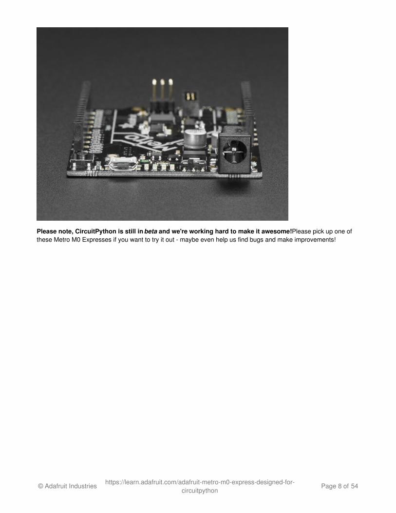
Please note, CircuitPython is still in beta and we're working hard to make it awesome! Please pick up one ofthese Metro M0 Expresses if you want to try it out - maybe even help us find bugs and make improvements!
© Adafruit Industries https://learn.adafruit.com/adafruit-metro-m0-express-designed-for-circuitpython
Page 8 of 54
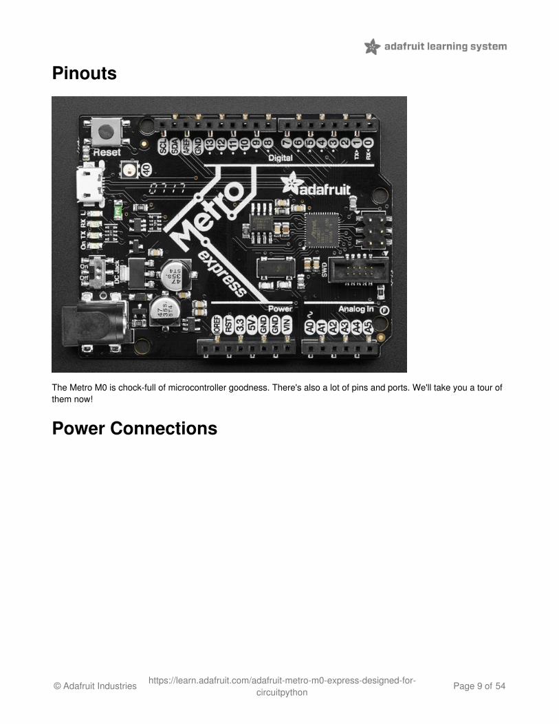
Pinouts
The Metro M0 is chock-full of microcontroller goodness. There's also a lot of pins and ports. We'll take you a tour ofthem now!
Power Connections
© Adafruit Industries https://learn.adafruit.com/adafruit-metro-m0-express-designed-for-circuitpython
Page 9 of 54
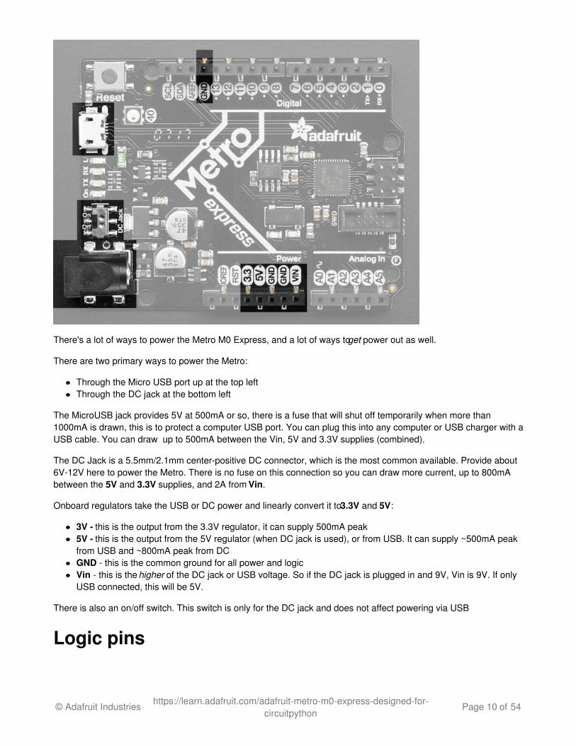
There's a lot of ways to power the Metro M0 Express, and a lot of ways to get power out as well.
There are two primary ways to power the Metro:
Through the Micro USB port up at the top leftThrough the DC jack at the bottom left
The MicroUSB jack provides 5V at 500mA or so, there is a fuse that will shut off temporarily when more than1000mA is drawn, this is to protect a computer USB port. You can plug this into any computer or USB charger with aUSB cable. You can draw up to 500mA between the Vin, 5V and 3.3V supplies (combined).
The DC Jack is a 5.5mm/2.1mm center-positive DC connector, which is the most common available. Provide about6V-12V here to power the Metro. There is no fuse on this connection so you can draw more current, up to 800mAbetween the 5V and 3.3V supplies, and 2A from Vin.
Onboard regulators take the USB or DC power and linearly convert it to 3.3V and 5V:
3V - this is the output from the 3.3V regulator, it can supply 500mA peak5V - this is the output from the 5V regulator (when DC jack is used), or from USB. It can supply ~500mA peakfrom USB and ~800mA peak from DCGND - this is the common ground for all power and logicVin - this is the higher of the DC jack or USB voltage. So if the DC jack is plugged in and 9V, Vin is 9V. If onlyUSB connected, this will be 5V.
There is also an on/off switch. This switch is only for the DC jack and does not affect powering via USB
Logic pins
© Adafruit Industries https://learn.adafruit.com/adafruit-metro-m0-express-designed-for-circuitpython
Page 10 of 54
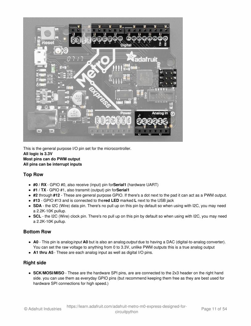
This is the general purpose I/O pin set for the microcontroller. All logic is 3.3VMost pins can do PWM outputAll pins can be interrupt inputs
Top Row
#0 / RX - GPIO #0, also receive (input) pin for Serial1 (hardware UART)#1 / TX - GPIO #1, also transmit (output) pin for Serial1#2 through #12 - These are general purpose GPIO. If there's a dot next to the pad it can act as a PWM output.#13 - GPIO #13 and is connected to the red LED marked L next to the USB jackSDA - the I2C (Wire) data pin. There's no pull up on this pin by default so when using with I2C, you may needa 2.2K-10K pullup.SCL - the I2C (Wire) clock pin. There's no pull up on this pin by default so when using with I2C, you may needa 2.2K-10K pullup.
Bottom Row
A0 - This pin is analog input A0 but is also an analog output due to having a DAC (digital-to-analog converter).You can set the raw voltage to anything from 0 to 3.3V, unlike PWM outputs this is a true analog outputA1 thru A5 - These are each analog input as well as digital I/O pins.
Right side
SCK/MOSI/MISO - These are the hardware SPI pins, are are connected to the 2x3 header on the right handside. you can use them as everyday GPIO pins (but recommend keeping them free as they are best used forhardware SPI connections for high speed.)
© Adafruit Industries https://learn.adafruit.com/adafruit-metro-m0-express-designed-for-circuitpython
Page 11 of 54
Additional analog inputs
In addition to the A0-A5 pins, there are extra analog inputs available
Digital #0 is also A6Digital #1 is also A7Digital #4 is also A8Digital #5 is also A9Digital #8 is also A10Digital #9 is also A11
These pins are available in CircuitPython under the board module. Names that start with # are prefixed with D andother names are as is. So #0 / RX above is available as board.D0 and board.RX for example.
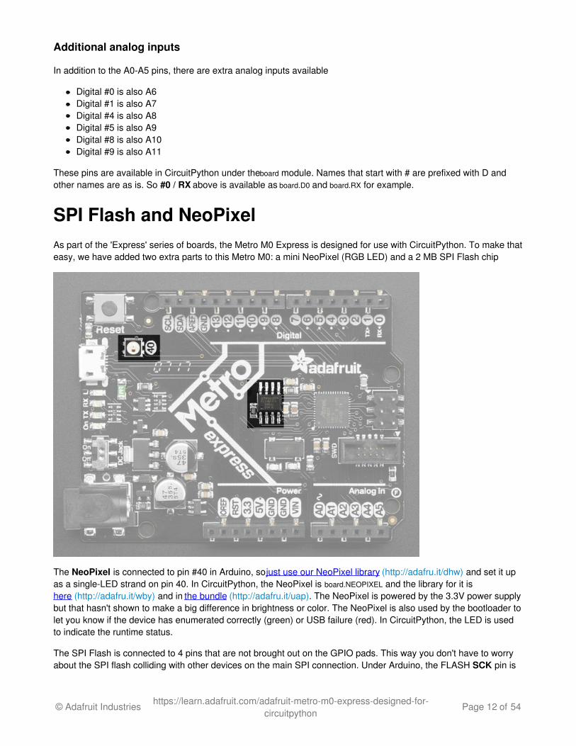
SPI Flash and NeoPixelAs part of the 'Express' series of boards, the Metro M0 Express is designed for use with CircuitPython. To make thateasy, we have added two extra parts to this Metro M0: a mini NeoPixel (RGB LED) and a 2 MB SPI Flash chip
The NeoPixel is connected to pin #40 in Arduino, so just use our NeoPixel library (http://adafru.it/dhw) and set it upas a single-LED strand on pin 40. In CircuitPython, the NeoPixel is board.NEOPIXEL and the library for it ishere (http://adafru.it/wby) and in the bundle (http://adafru.it/uap). The NeoPixel is powered by the 3.3V power supplybut that hasn't shown to make a big difference in brightness or color. The NeoPixel is also used by the bootloader tolet you know if the device has enumerated correctly (green) or USB failure (red). In CircuitPython, the LED is usedto indicate the runtime status.
The SPI Flash is connected to 4 pins that are not brought out on the GPIO pads. This way you don't have to worryabout the SPI flash colliding with other devices on the main SPI connection. Under Arduino, the FLASH SCK pin is
© Adafruit Industries https://learn.adafruit.com/adafruit-metro-m0-express-designed-for-circuitpython
Page 12 of 54
#38, MISO is #36, MOSI is #37, and CS is #39. If you use Metro M0 Express as your board type, you'll be able toaccess the Flash SPI port under SPI1 - this is a fully new hardware SPI device separate from the GPIO pins on theoutside edge of the Feather. In CircuitPython, the SPI flash is used natively by the interpretter and is read-only touser code, instead the Flash just shows up as the writeable disk drive!
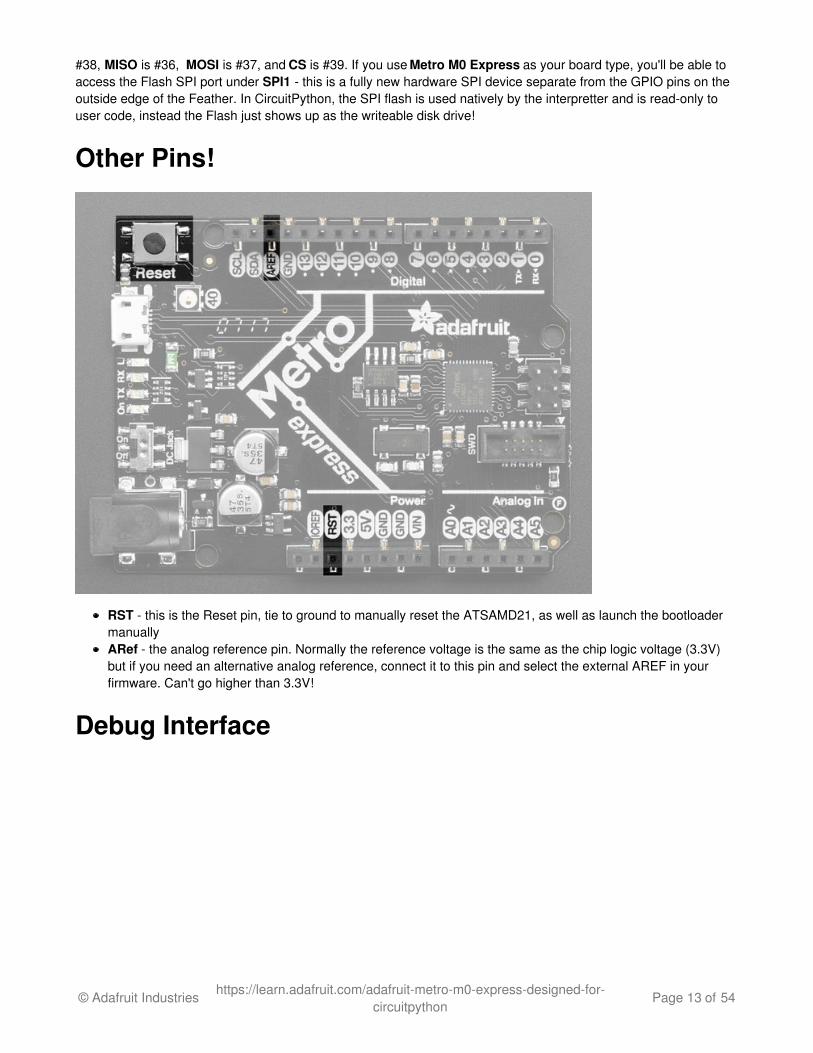
Other Pins!
RST - this is the Reset pin, tie to ground to manually reset the ATSAMD21, as well as launch the bootloadermanuallyARef - the analog reference pin. Normally the reference voltage is the same as the chip logic voltage (3.3V)but if you need an alternative analog reference, connect it to this pin and select the external AREF in yourfirmware. Can't go higher than 3.3V!
Debug Interface
© Adafruit Industries https://learn.adafruit.com/adafruit-metro-m0-express-designed-for-circuitpython
Page 13 of 54
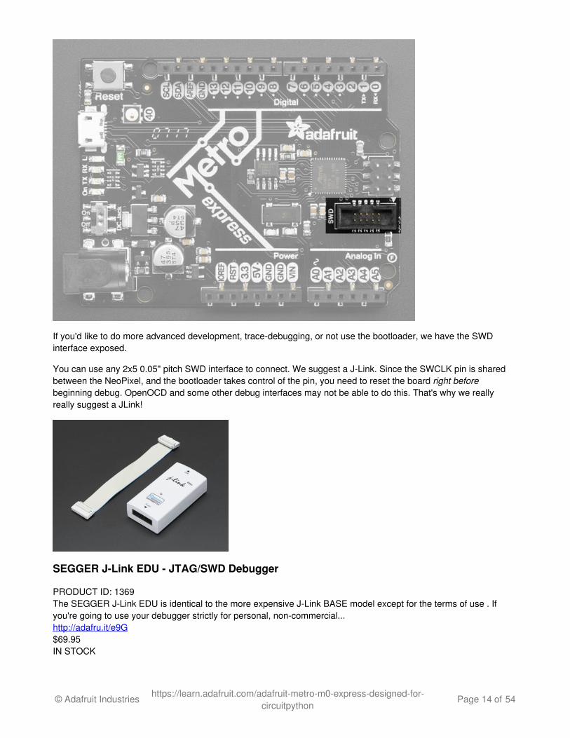
If you'd like to do more advanced development, trace-debugging, or not use the bootloader, we have the SWDinterface exposed.
You can use any 2x5 0.05" pitch SWD interface to connect. We suggest a J-Link. Since the SWCLK pin is sharedbetween the NeoPixel, and the bootloader takes control of the pin, you need to reset the board right beforebeginning debug. OpenOCD and some other debug interfaces may not be able to do this. That's why we reallyreally suggest a JLink!
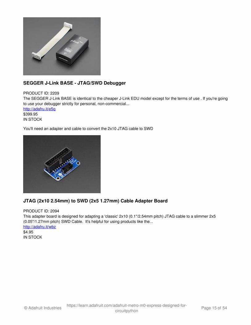
SEGGER J-Link EDU - JTAG/SWD Debugger
PRODUCT ID: 1369The SEGGER J-Link EDU is identical to the more expensive J-Link BASE model except for the terms of use . Ifyou're going to use your debugger strictly for personal, non-commercial...http://adafru.it/e9G$69.95IN STOCK
© Adafruit Industries https://learn.adafruit.com/adafruit-metro-m0-express-designed-for-circuitpython
Page 14 of 54
SEGGER J-Link BASE - JTAG/SWD Debugger
PRODUCT ID: 2209The SEGGER J-Link BASE is identical to the cheaper J-Link EDU model except for the terms of use . If you're goingto use your debugger strictly for personal, non-commercial...http://adafru.it/e5q$399.95IN STOCK
You'll need an adapter and cable to convert the 2x10 JTAG cable to SWD
JTAG (2x10 2.54mm) to SWD (2x5 1.27mm) Cable Adapter Board
PRODUCT ID: 2094This adapter board is designed for adapting a 'classic' 2x10 (0.1"/2.54mm pitch) JTAG cable to a slimmer 2x5(0.05"/1.27mm pitch) SWD Cable. It's helpful for using products like the...http://adafru.it/wbz$4.95IN STOCK
© Adafruit Industries https://learn.adafruit.com/adafruit-metro-m0-express-designed-for-circuitpython
Page 15 of 54
10-pin 2x5 Socket-Socket 1.27mm IDC (SWD) Cable - 150mm long
PRODUCT ID: 1675These little cables are handy when programming or debugging a tiny board that uses 10-pin 1.27mm (0.05") pitchSWD programming connectors. We see these connectors often on ARM Cortex...http://adafru.it/wbA$2.95IN STOCK
© Adafruit Industries https://learn.adafruit.com/adafruit-metro-m0-express-designed-for-circuitpython
Page 16 of 54

UF2 Bootloader DetailsThis is an information page for advanced users who are curious how we get code from your computer into yourExpress board!
Adafruit Express boards feature an improved bootloader that makes it easier than ever to flash different code ontothe microcontroller. This bootloader makes it easy to switch between Microsoft MakeCode, CircuitPython andArduino.
Instead of needing drivers or a separate program for flashing (say, bossac, jlink or avrdude), one can simply drag a fileonto a removable drive.
The format of the file is a little special. Due to 'operating system woes' you cannot just drag a binary or hex file (trustus, we tried it, it isn't cross-platform compatible). Instead, the format of the file has extra information to help thebootloader know where the data goes. The format is called UF2 (USB Flashing Format). Microsoft MakeCodegenerates UF2s for flashing and CircuitPython releases are also available as UF2. You can also create your ownUF2s from binary files using uf2tool, available here. (http://adafru.it/vPE)
The bootloader is also BOSSA compatible, so it can be used with the Arduino IDE which expects a BOSSAbootloader on ATSAMD-based boards
For more information about UF2, you can read a bunch more at the MakeCode blog (http://adafru.it/w5A), thencheck out the UF2 file format specification (http://adafru.it/vPE) and to build your own bootloader for ATSAMD-based boards, visit Microsoft UF2-SAMD github repository (http://adafru.it/vPF).
The bootloader is not needed when changing your CircuitPython code. Its only needed when upgrading theCircuitPython core or changing between CircuitPython, Arduino and Microsoft MakeCode.
Entering Bootloader ModeThe first step to loading new code onto your board is triggering the bootloader. It is easily done by double tappingthe reset button. Once the bootloader is active you will see the small red LED fade in and out and a new drive willappear on your computer with a name ending in BOOT. For example, feathers show up as FEATHERBOOT whilethe new CircuitPlayground shows up as CPLAYBOOT.
Furthermore, when the bootloader is active, it will change the color of one or more onboard neopixels to indicate theconnection status, red for disconnected and green for connected. If the board is plugged in but still showing that itsdisconnected, try a different USB cable. Some cables only provide power with no communication.
For example, here is a Feather M0 Express running a colorful Neopixel swirl. When the reset button is doubleclicked (about half second between each click) the NeoPixel will stay green to let you know the bootloader is active.When the reset button is clicked once, the 'user program' (NeoPixel color swirl) restarts.
© Adafruit Industries https://learn.adafruit.com/adafruit-metro-m0-express-designed-for-circuitpython
Page 17 of 54
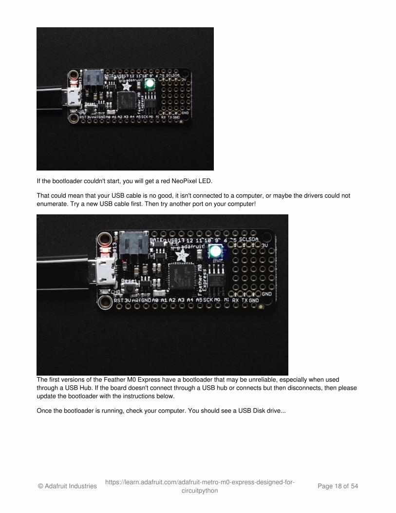
If the bootloader couldn't start, you will get a red NeoPixel LED.
That could mean that your USB cable is no good, it isn't connected to a computer, or maybe the drivers could notenumerate. Try a new USB cable first. Then try another port on your computer!
The first versions of the Feather M0 Express have a bootloader that may be unreliable, especially when usedthrough a USB Hub. If the board doesn't connect through a USB hub or connects but then disconnects, then pleaseupdate the bootloader with the instructions below.
Once the bootloader is running, check your computer. You should see a USB Disk drive...
© Adafruit Industries https://learn.adafruit.com/adafruit-metro-m0-express-designed-for-circuitpython
Page 18 of 54
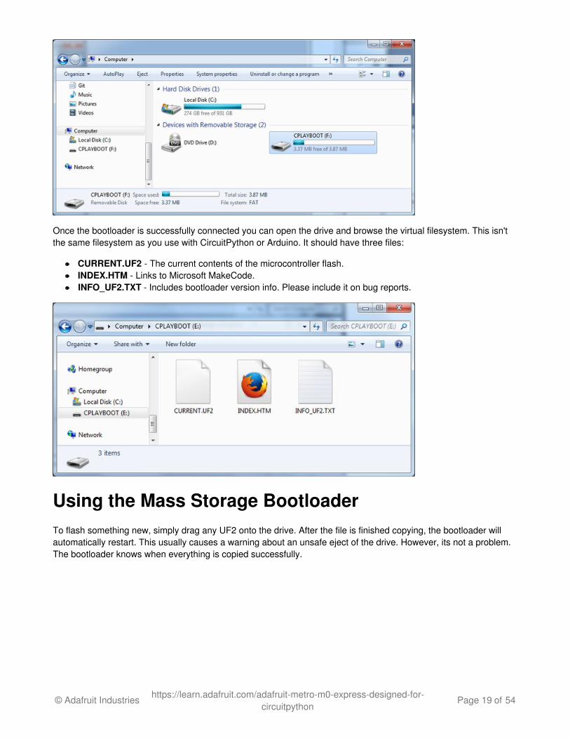
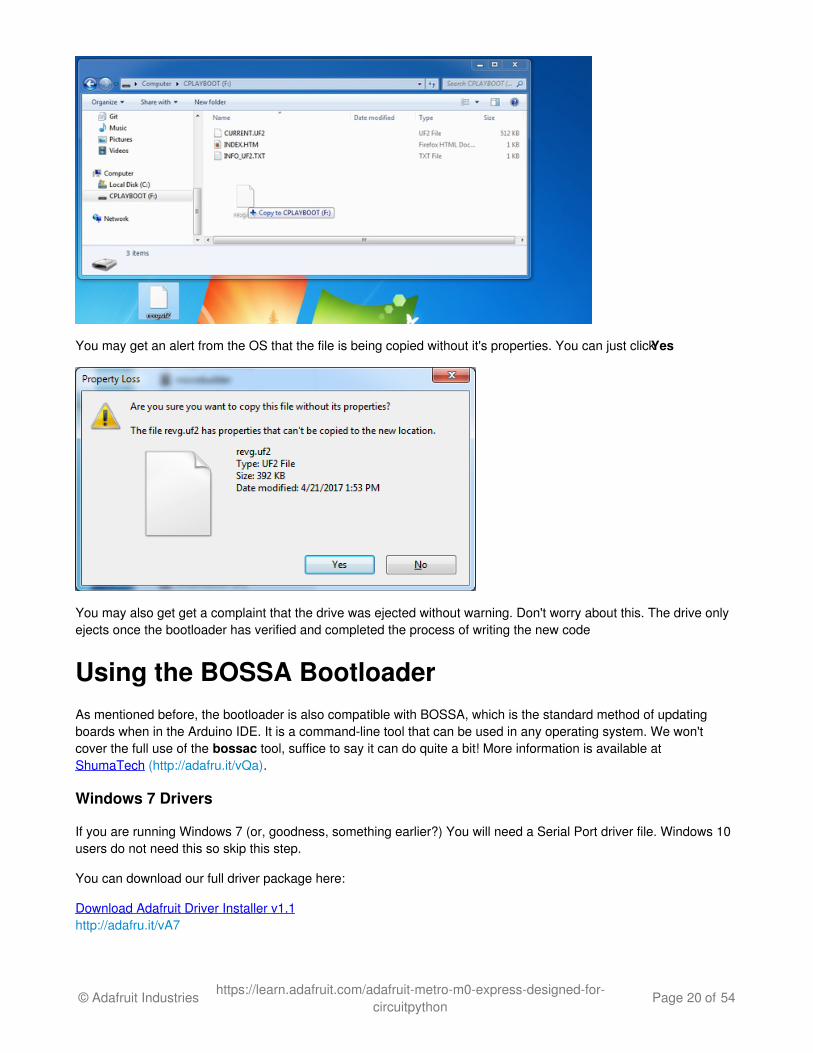
Once the bootloader is successfully connected you can open the drive and browse the virtual filesystem. This isn'tthe same filesystem as you use with CircuitPython or Arduino. It should have three files:
CURRENT.UF2 - The current contents of the microcontroller flash. INDEX.HTM - Links to Microsoft MakeCode. INFO_UF2.TXT - Includes bootloader version info. Please include it on bug reports.
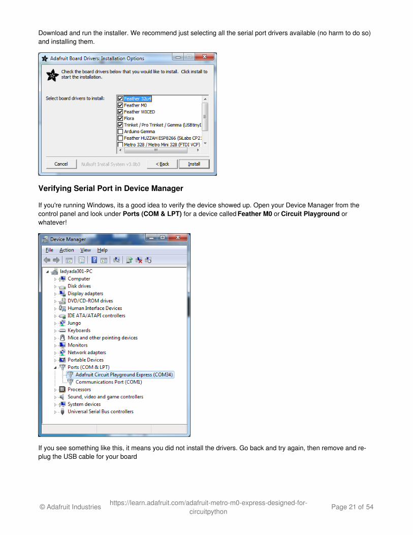
Using the Mass Storage BootloaderTo flash something new, simply drag any UF2 onto the drive. After the file is finished copying, the bootloader willautomatically restart. This usually causes a warning about an unsafe eject of the drive. However, its not a problem.The bootloader knows when everything is copied successfully.
© Adafruit Industries https://learn.adafruit.com/adafruit-metro-m0-express-designed-for-circuitpython
Page 19 of 54
You may get an alert from the OS that the file is being copied without it's properties. You can just click Yes
You may also get get a complaint that the drive was ejected without warning. Don't worry about this. The drive onlyejects once the bootloader has verified and completed the process of writing the new code
Using the BOSSA BootloaderAs mentioned before, the bootloader is also compatible with BOSSA, which is the standard method of updatingboards when in the Arduino IDE. It is a command-line tool that can be used in any operating system. We won'tcover the full use of the bossac tool, suffice to say it can do quite a bit! More information is available atShumaTech (http://adafru.it/vQa).
Windows 7 Drivers
If you are running Windows 7 (or, goodness, something earlier?) You will need a Serial Port driver file. Windows 10users do not need this so skip this step.
You can download our full driver package here:
Download Adafruit Driver Installer v1.1http://adafru.it/vA7
© Adafruit Industries https://learn.adafruit.com/adafruit-metro-m0-express-designed-for-circuitpython
Page 20 of 54
Download and run the installer. We recommend just selecting all the serial port drivers available (no harm to do so)and installing them.
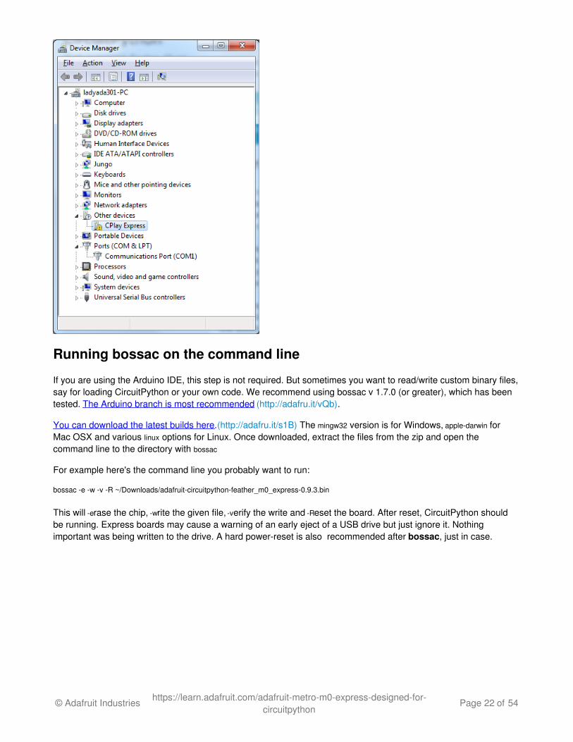
Verifying Serial Port in Device Manager
If you're running Windows, its a good idea to verify the device showed up. Open your Device Manager from thecontrol panel and look under Ports (COM & LPT) for a device called Feather M0 or Circuit Playground orwhatever!
If you see something like this, it means you did not install the drivers. Go back and try again, then remove and re-plug the USB cable for your board
© Adafruit Industries https://learn.adafruit.com/adafruit-metro-m0-express-designed-for-circuitpython
Page 21 of 54
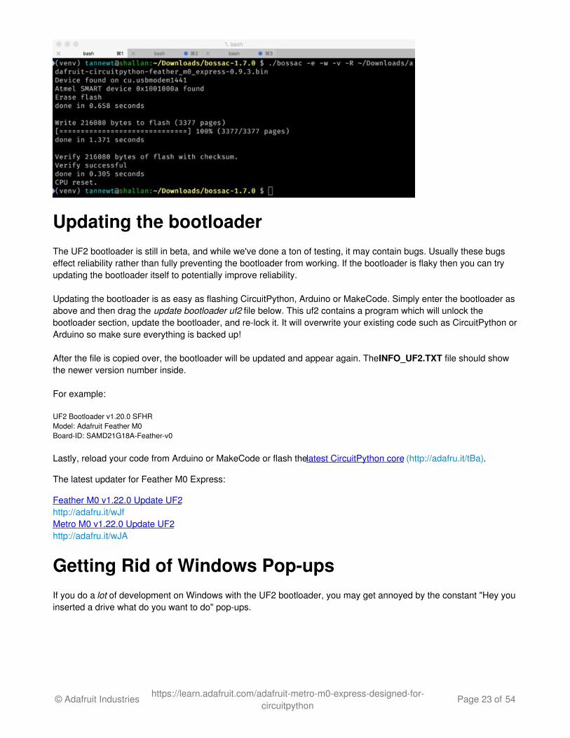
Running bossac on the command line
If you are using the Arduino IDE, this step is not required. But sometimes you want to read/write custom binary files,say for loading CircuitPython or your own code. We recommend using bossac v 1.7.0 (or greater), which has beentested. The Arduino branch is most recommended (http://adafru.it/vQb).
You can download the latest builds here. (http://adafru.it/s1B) The mingw32 version is for Windows, apple-darwin forMac OSX and various linux options for Linux. Once downloaded, extract the files from the zip and open thecommand line to the directory with bossac
For example here's the command line you probably want to run:
bossac -e -w -v -R ~/Downloads/adafruit-circuitpython-feather_m0_express-0.9.3.bin
This will -erase the chip, -write the given file, -verify the write and -Reset the board. After reset, CircuitPython shouldbe running. Express boards may cause a warning of an early eject of a USB drive but just ignore it. Nothingimportant was being written to the drive. A hard power-reset is also recommended after bossac, just in case.
© Adafruit Industries https://learn.adafruit.com/adafruit-metro-m0-express-designed-for-circuitpython
Page 22 of 54
Updating the bootloaderThe UF2 bootloader is still in beta, and while we've done a ton of testing, it may contain bugs. Usually these bugseffect reliability rather than fully preventing the bootloader from working. If the bootloader is flaky then you can tryupdating the bootloader itself to potentially improve reliability.
Updating the bootloader is as easy as flashing CircuitPython, Arduino or MakeCode. Simply enter the bootloader asabove and then drag the update bootloader uf2 file below. This uf2 contains a program which will unlock thebootloader section, update the bootloader, and re-lock it. It will overwrite your existing code such as CircuitPython orArduino so make sure everything is backed up!
After the file is copied over, the bootloader will be updated and appear again. The INFO_UF2.TXT file should showthe newer version number inside.
For example:
UF2 Bootloader v1.20.0 SFHRModel: Adafruit Feather M0Board-ID: SAMD21G18A-Feather-v0
Lastly, reload your code from Arduino or MakeCode or flash the latest CircuitPython core (http://adafru.it/tBa).
The latest updater for Feather M0 Express:
Feather M0 v1.22.0 Update UF2http://adafru.it/wJfMetro M0 v1.22.0 Update UF2http://adafru.it/wJA
Getting Rid of Windows Pop-upsIf you do a lot of development on Windows with the UF2 bootloader, you may get annoyed by the constant "Hey youinserted a drive what do you want to do" pop-ups.
© Adafruit Industries https://learn.adafruit.com/adafruit-metro-m0-express-designed-for-circuitpython
Page 23 of 54
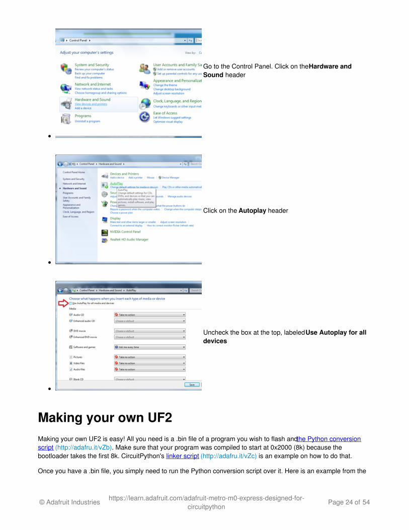
Go to the Control Panel. Click on the Hardware andSound header
Click on the Autoplay header
Uncheck the box at the top, labeled Use Autoplay for alldevices
Making your own UF2Making your own UF2 is easy! All you need is a .bin file of a program you wish to flash and the Python conversionscript (http://adafru.it/vZb). Make sure that your program was compiled to start at 0x2000 (8k) because thebootloader takes the first 8k. CircuitPython's linker script (http://adafru.it/vZc) is an example on how to do that.
Once you have a .bin file, you simply need to run the Python conversion script over it. Here is an example from the
© Adafruit Industries https://learn.adafruit.com/adafruit-metro-m0-express-designed-for-circuitpython
Page 24 of 54

directory with uf2conv.py:
uf2conv.py -c -o build-circuitplayground_express/revg.uf2 build-circuitplayground_express/revg.bin
This will produce a revg.uf2 file in the same directory as the source revg.bin. The uf2 can then be flashed in thesame way as above.
© Adafruit Industries https://learn.adafruit.com/adafruit-metro-m0-express-designed-for-circuitpython
Page 25 of 54
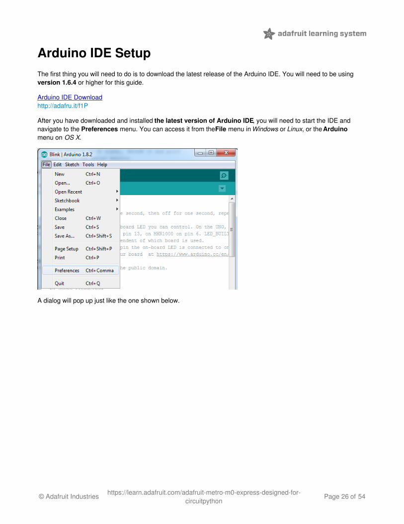
Arduino IDE SetupThe first thing you will need to do is to download the latest release of the Arduino IDE. You will need to be usingversion 1.6.4 or higher for this guide.
Arduino IDE Downloadhttp://adafru.it/f1P
After you have downloaded and installed the latest version of Arduino IDE, you will need to start the IDE andnavigate to the Preferences menu. You can access it from the File menu in Windows or Linux, or the Arduinomenu on OS X.
A dialog will pop up just like the one shown below.
© Adafruit Industries https://learn.adafruit.com/adafruit-metro-m0-express-designed-for-circuitpython
Page 26 of 54
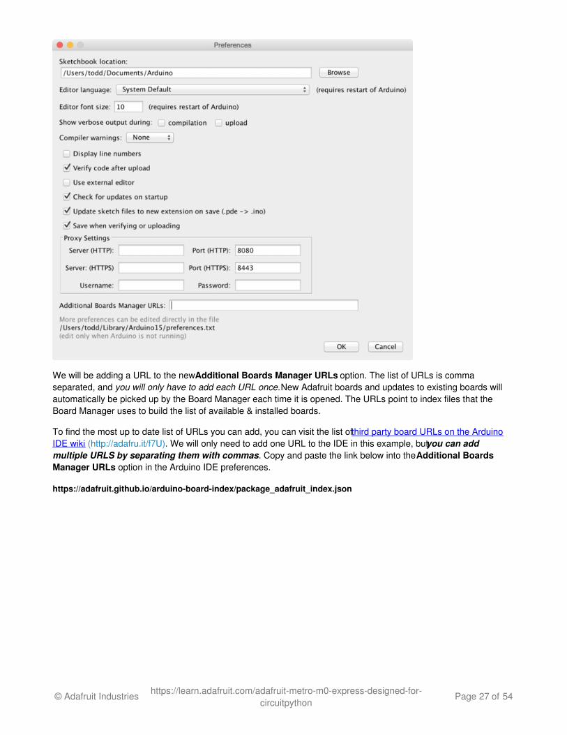
We will be adding a URL to the new Additional Boards Manager URLs option. The list of URLs is commaseparated, and you will only have to add each URL once. New Adafruit boards and updates to existing boards willautomatically be picked up by the Board Manager each time it is opened. The URLs point to index files that theBoard Manager uses to build the list of available & installed boards.
To find the most up to date list of URLs you can add, you can visit the list of third party board URLs on the ArduinoIDE wiki (http://adafru.it/f7U). We will only need to add one URL to the IDE in this example, but you can addmultiple URLS by separating them with commas. Copy and paste the link below into the Additional BoardsManager URLs option in the Arduino IDE preferences.
https://adafruit.github.io/arduino-board-index/package_adafruit_index.json
© Adafruit Industries https://learn.adafruit.com/adafruit-metro-m0-express-designed-for-circuitpython
Page 27 of 54
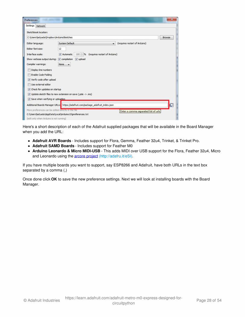
Here's a short description of each of the Adafruit supplied packages that will be available in the Board Managerwhen you add the URL:
Adafruit AVR Boards - Includes support for Flora, Gemma, Feather 32u4, Trinket, & Trinket Pro.Adafruit SAMD Boards - Includes support for Feather M0Arduino Leonardo & Micro MIDI-USB - This adds MIDI over USB support for the Flora, Feather 32u4, Microand Leonardo using the arcore project (http://adafru.it/eSI).
If you have multiple boards you want to support, say ESP8266 and Adafruit, have both URLs in the text boxseparated by a comma (,)
Once done click OK to save the new preference settings. Next we will look at installing boards with the BoardManager.
© Adafruit Industries https://learn.adafruit.com/adafruit-metro-m0-express-designed-for-circuitpython
Page 28 of 54
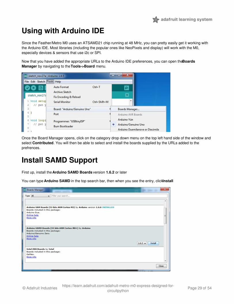
Using with Arduino IDESince the Feather/Metro M0 uses an ATSAMD21 chip running at 48 MHz, you can pretty easily get it working withthe Arduino IDE. Most libraries (including the popular ones like NeoPixels and display) will work with the M0,especially devices & sensors that use i2c or SPI.
Now that you have added the appropriate URLs to the Arduino IDE preferences, you can open the BoardsManager by navigating to the Tools->Board menu.
Once the Board Manager opens, click on the category drop down menu on the top left hand side of the window andselect Contributed. You will then be able to select and install the boards supplied by the URLs added to theprefrences.
Install SAMD SupportFirst up, install the Arduino SAMD Boards version 1.6.2 or later
You can type Arduino SAMD in the top search bar, then when you see the entry, click Install
© Adafruit Industries https://learn.adafruit.com/adafruit-metro-m0-express-designed-for-circuitpython
Page 29 of 54
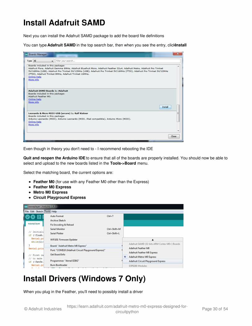
Install Adafruit SAMDNext you can install the Adafruit SAMD package to add the board file definitions
You can type Adafruit SAMD in the top search bar, then when you see the entry, click Install
Even though in theory you don't need to - I recommend rebooting the IDE
Quit and reopen the Arduino IDE to ensure that all of the boards are properly installed. You should now be able toselect and upload to the new boards listed in the Tools->Board menu.
Select the matching board, the current options are:
Feather M0 (for use with any Feather M0 other than the Express)Feather M0 ExpressMetro M0 ExpressCircuit Playground Express
Install Drivers (Windows 7 Only)When you plug in the Feather, you'll need to possibly install a driver
© Adafruit Industries https://learn.adafruit.com/adafruit-metro-m0-express-designed-for-circuitpython
Page 30 of 54
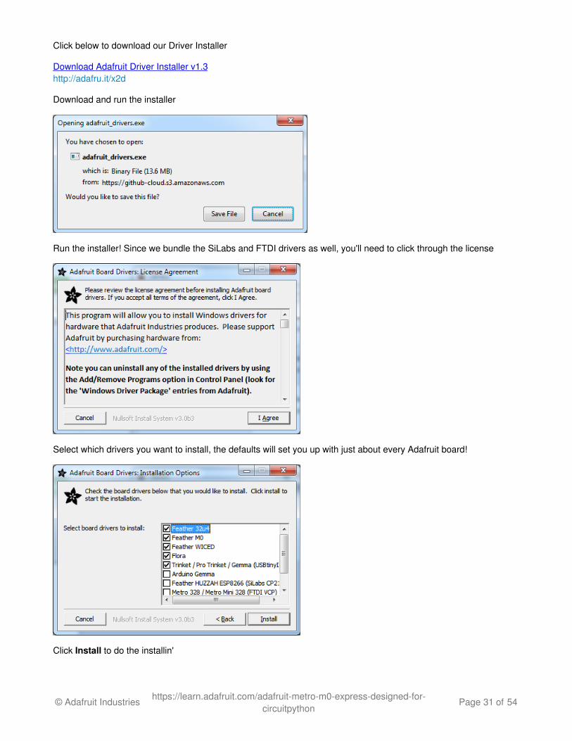
Click below to download our Driver Installer
Download Adafruit Driver Installer v1.3http://adafru.it/x2d
Download and run the installer
Run the installer! Since we bundle the SiLabs and FTDI drivers as well, you'll need to click through the license
Select which drivers you want to install, the defaults will set you up with just about every Adafruit board!
Click Install to do the installin'
© Adafruit Industries https://learn.adafruit.com/adafruit-metro-m0-express-designed-for-circuitpython
Page 31 of 54
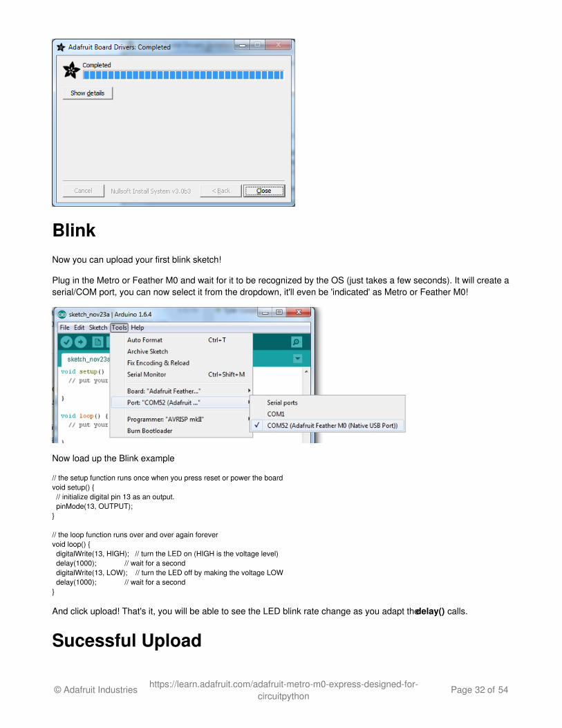
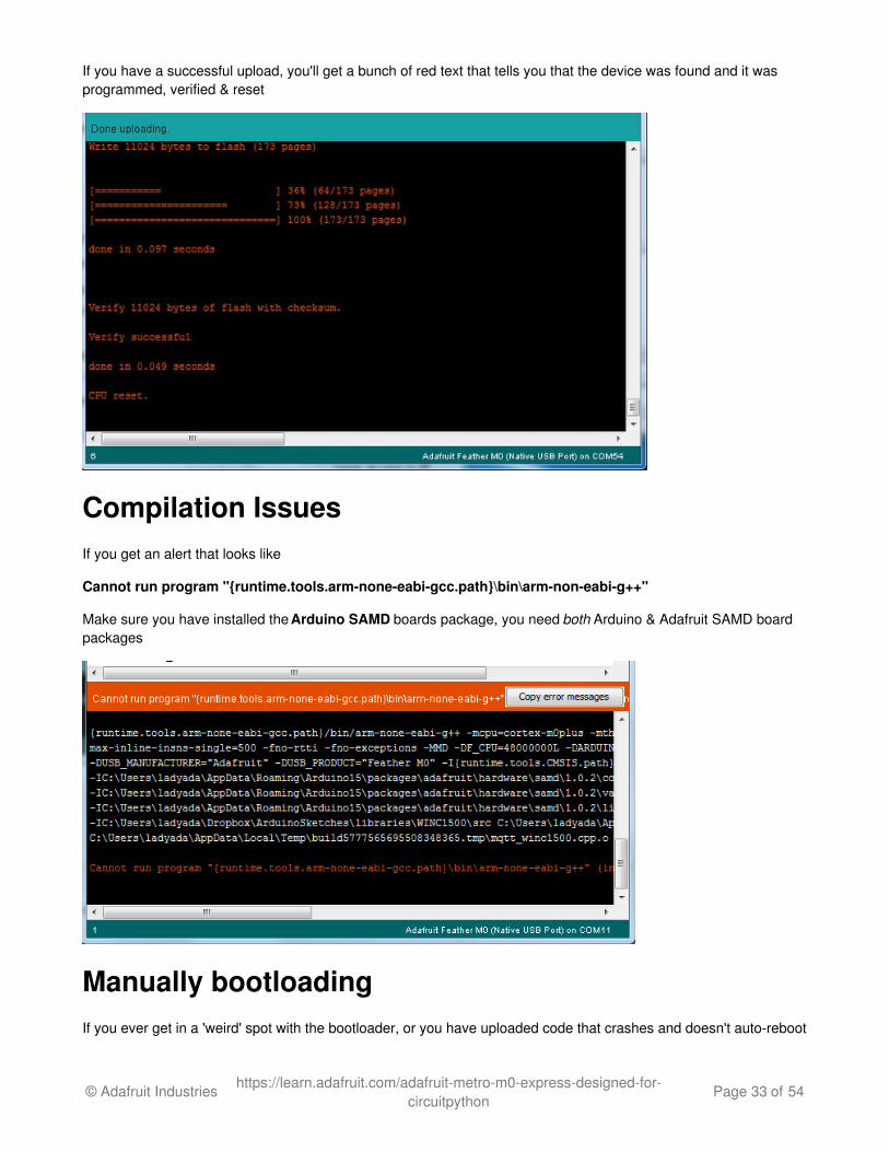
BlinkNow you can upload your first blink sketch!
Plug in the Metro or Feather M0 and wait for it to be recognized by the OS (just takes a few seconds). It will create aserial/COM port, you can now select it from the dropdown, it'll even be 'indicated' as Metro or Feather M0!
Now load up the Blink example
// the setup function runs once when you press reset or power the boardvoid setup() { // initialize digital pin 13 as an output. pinMode(13, OUTPUT);}
// the loop function runs over and over again forevervoid loop() { digitalWrite(13, HIGH); // turn the LED on (HIGH is the voltage level) delay(1000); // wait for a second digitalWrite(13, LOW); // turn the LED off by making the voltage LOW delay(1000); // wait for a second}
And click upload! That's it, you will be able to see the LED blink rate change as you adapt the delay() calls.
Sucessful Upload
© Adafruit Industries https://learn.adafruit.com/adafruit-metro-m0-express-designed-for-circuitpython
Page 32 of 54
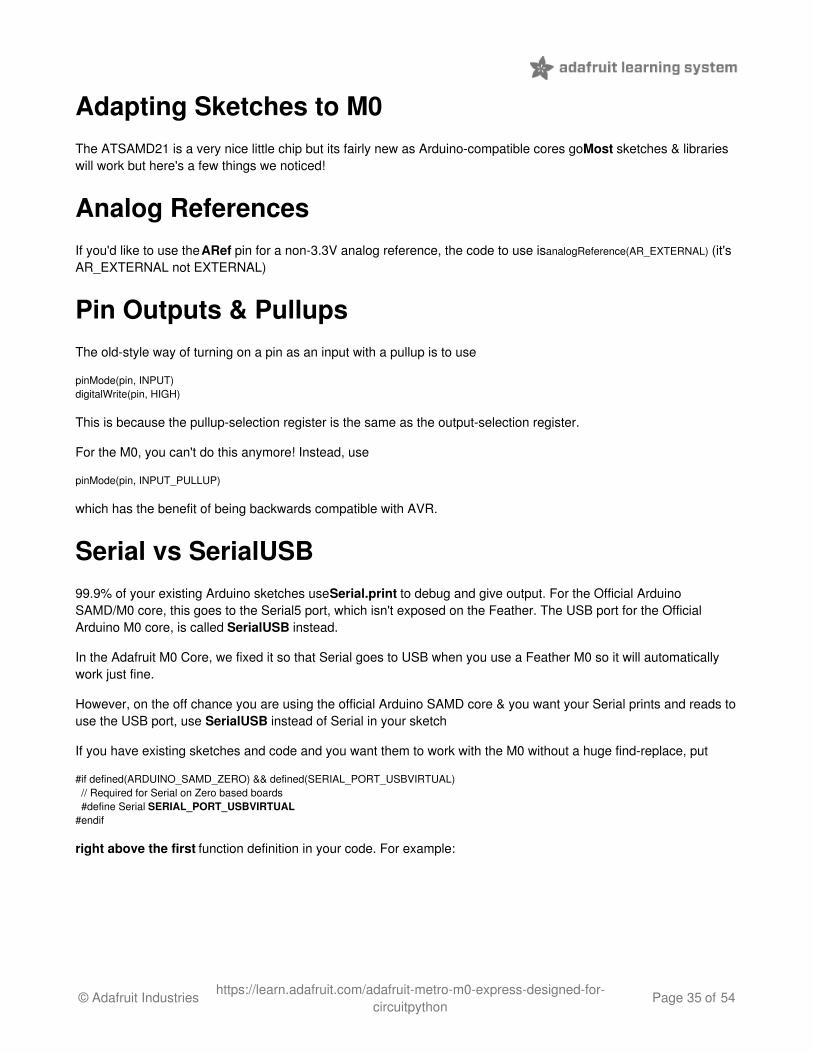
If you have a successful upload, you'll get a bunch of red text that tells you that the device was found and it wasprogrammed, verified & reset
Compilation IssuesIf you get an alert that looks like
Cannot run program "{runtime.tools.arm-none-eabi-gcc.path}\bin\arm-non-eabi-g++"
Make sure you have installed the Arduino SAMD boards package, you need both Arduino & Adafruit SAMD boardpackages
Manually bootloadingIf you ever get in a 'weird' spot with the bootloader, or you have uploaded code that crashes and doesn't auto-reboot
© Adafruit Industries https://learn.adafruit.com/adafruit-metro-m0-express-designed-for-circuitpython
Page 33 of 54

into the bootloader, click the RST button twice (like a double-click)to get back into the bootloader.
The red LED will pulse, so you know that its in bootloader mode.
Once it is in bootloader mode, you can select the newly created COM/Serial port and re-try uploading.
You may need to go back and reselect the 'normal' USB serial port next time you want to use the normal upload.
Ubuntu & Linux Issue FixNote if you're using Ubuntu 15.04 (or perhaps other more recent Linux distributions) there is an issue with themodem manager service which causes the Bluefruit LE micro to be difficult to program. If you run into errors like"device or resource busy", "bad file descriptor", or "port is busy" when attempting to program then you are hittingthis issue. (http://adafru.it/sHE)
The fix for this issue is to make sure Adafruit's custom udev rules are applied to your system. One of these rules ismade to configure modem manager not to touch the Feather board and will fix the programming difficulty issue. Follow the steps for installing Adafruit's udev rules on this page. (http://adafru.it/iOE)
© Adafruit Industries https://learn.adafruit.com/adafruit-metro-m0-express-designed-for-circuitpython
Page 34 of 54
Adapting Sketches to M0The ATSAMD21 is a very nice little chip but its fairly new as Arduino-compatible cores go. Most sketches & librarieswill work but here's a few things we noticed!
Analog ReferencesIf you'd like to use the ARef pin for a non-3.3V analog reference, the code to use is analogReference(AR_EXTERNAL) (it'sAR_EXTERNAL not EXTERNAL)
Pin Outputs & PullupsThe old-style way of turning on a pin as an input with a pullup is to use
pinMode(pin, INPUT)digitalWrite(pin, HIGH)
This is because the pullup-selection register is the same as the output-selection register.
For the M0, you can't do this anymore! Instead, use
pinMode(pin, INPUT_PULLUP)
which has the benefit of being backwards compatible with AVR.
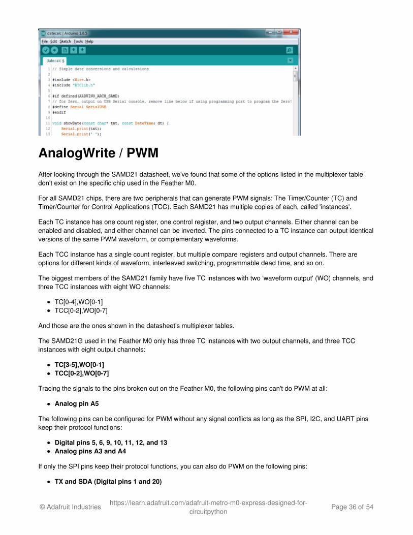
Serial vs SerialUSB99.9% of your existing Arduino sketches use Serial.print to debug and give output. For the Official ArduinoSAMD/M0 core, this goes to the Serial5 port, which isn't exposed on the Feather. The USB port for the OfficialArduino M0 core, is called SerialUSB instead.
In the Adafruit M0 Core, we fixed it so that Serial goes to USB when you use a Feather M0 so it will automaticallywork just fine.
However, on the off chance you are using the official Arduino SAMD core & you want your Serial prints and reads touse the USB port, use SerialUSB instead of Serial in your sketch
If you have existing sketches and code and you want them to work with the M0 without a huge find-replace, put
#if defined(ARDUINO_SAMD_ZERO) && defined(SERIAL_PORT_USBVIRTUAL) // Required for Serial on Zero based boards #define Serial SERIAL_PORT_USBVIRTUAL#endif
right above the first function definition in your code. For example:
© Adafruit Industries https://learn.adafruit.com/adafruit-metro-m0-express-designed-for-circuitpython
Page 35 of 54
AnalogWrite / PWMAfter looking through the SAMD21 datasheet, we've found that some of the options listed in the multiplexer tabledon't exist on the specific chip used in the Feather M0.
For all SAMD21 chips, there are two peripherals that can generate PWM signals: The Timer/Counter (TC) andTimer/Counter for Control Applications (TCC). Each SAMD21 has multiple copies of each, called 'instances'.
Each TC instance has one count register, one control register, and two output channels. Either channel can beenabled and disabled, and either channel can be inverted. The pins connected to a TC instance can output identicalversions of the same PWM waveform, or complementary waveforms.
Each TCC instance has a single count register, but multiple compare registers and output channels. There areoptions for different kinds of waveform, interleaved switching, programmable dead time, and so on.
The biggest members of the SAMD21 family have five TC instances with two 'waveform output' (WO) channels, andthree TCC instances with eight WO channels:
TC[0-4],WO[0-1]TCC[0-2],WO[0-7]
And those are the ones shown in the datasheet's multiplexer tables.
The SAMD21G used in the Feather M0 only has three TC instances with two output channels, and three TCCinstances with eight output channels:
TC[3-5],WO[0-1]TCC[0-2],WO[0-7]
Tracing the signals to the pins broken out on the Feather M0, the following pins can't do PWM at all:
Analog pin A5
The following pins can be configured for PWM without any signal conflicts as long as the SPI, I2C, and UART pinskeep their protocol functions:
Digital pins 5, 6, 9, 10, 11, 12, and 13Analog pins A3 and A4
If only the SPI pins keep their protocol functions, you can also do PWM on the following pins:
TX and SDA (Digital pins 1 and 20)
© Adafruit Industries https://learn.adafruit.com/adafruit-metro-m0-express-designed-for-circuitpython
Page 36 of 54
Missing header filesthere might be code that uses libraries that are not supported by the M0 core. For example if you have a line with
#include <util/delay.h>
you'll get an error that says
fatal error: util/delay.h: No such file or directory #include <util/delay.h> ^compilation terminated.Error compiling.
In which case you can simply locate where the line is (the error will give you the file name and line number) and'wrap it' with #ifdef's so it looks like:
#if !defined(ARDUINO_ARCH_SAM) && !defined(ARDUINO_ARCH_SAMD) && !defined(ESP8266) && !defined(ARDUINO_ARCH_STM32F2) #include <util/delay.h>#endif
The above will also make sure that header file isn't included for other architectures
If the #include is in the arduino sketch itself, you can try just removing the line.
Bootloader LaunchingFor most other AVRs, clicking reset while plugged into USB will launch the bootloader manually, the bootloader willtime out after a few seconds. For the M0, you'll need to double click the button. You will see a pulsing red LED to letyou know you're in bootloader mode. Once in that mode, it wont time out! Click reset again if you want to go back tolaunching code
Aligned Memory AccessThis is a little less likely to happen to you but it happened to me! If you're used to 8-bit platforms, you can do thisnice thing where you can typecast variables around. e.g.
uint8_t mybuffer[4];float f = (float)mybuffer;
You can't be guaranteed that this will work on a 32-bit platform because mybuffer might not be aligned to a 2 or 4-byte boundary. The ARM Cortex-M0 can only directly access data on 16-bit boundaries (every 2 or 4 bytes). Tryingto access an odd-boundary byte (on a 1 or 3 byte location) will cause a Hard Fault and stop the MCU. Thankfully,there's an easy work around ... just use memcpy!
uint8_t mybuffer[4];float f;memcpy(f, mybuffer, 4)
Floating Point ConversionLike the AVR Arduinos, the M0 library does not have full support for converting floating point numbers to ASCIIstrings. Functions like sprintf will not convert floating point. Fortunately, the standard AVR-LIBC library includes thedtostrf function which can handle the conversion for you.
© Adafruit Industries https://learn.adafruit.com/adafruit-metro-m0-express-designed-for-circuitpython
Page 37 of 54
Unfortunately, the M0 run-time library does not have dtostrf. You may see some references to using #include<avr/dtostrf.h> to get dtostrf in your code. And while it will compile, it does not work.
Instead, check out this thread to find a working dtostrf function you can include in your code:
http://forum.arduino.cc/index.php?topic=368720.0 (http://adafru.it/lFS)
How Much RAM Available?The ATSAMD21G18 has 32K of RAM, but you still might need to track it for some reason. You can do so with thishandy function:
extern "C" char *sbrk(int i);
int FreeRam () { char stack_dummy = 0; return &stack_dummy - sbrk(0);}
Thx to http://forum.arduino.cc/index.php?topic=365830.msg2542879#msg2542879 (http://adafru.it/m6D) for the tip!
Storing data in FLASHIf you're used to AVR, you've probably used PROGMEM to let the compiler know you'd like to put a variable orstring in flash memory to save on RAM. On the ARM, its a little easier, simply add const before the variable name:
const char str[] = "My very long string";
That string is now in FLASH. You can manipulate the string just like RAM data, the compiler will automatically readfrom FLASH so you dont need special progmem-knowledgeable functions.
You can verify where data is stored by printing out the address:Serial.print("Address of str $"); Serial.println((int)&str, HEX);
If the address is $2000000 or larger, its in SRAM. If the address is between $0000 and $3FFFF Then it is in FLASH
© Adafruit Industries https://learn.adafruit.com/adafruit-metro-m0-express-designed-for-circuitpython
Page 38 of 54
Using SPI FlashOne of the best features of the M0 express board is a small SPI flash memory chip built into the board. Thismemory can be used for almost any purpose like storing data files, Python code, and more. Think of it like a littleSD card that is always connected to the board, and in fact with Arduino you can access the memory using a librarythat is very similar to the Arduino SD card library (http://adafru.it/ucu). You can even read and write files thatCircuitPython stores on the flash chip!
To use the flash memory with Arduino you'll need to install the Adafruit SPI Flash Memorylibrary (http://adafru.it/wbt) in the Arduino IDE. Click the button below to download the source for this library, openthe zip file, and then copy it into an Adafruit_SPIFlash folder (remove the -master GitHub adds to the downloadedzip and folder) in the Arduino library folder on your computer (http://adafru.it/dNR):
Download Adafruit_SPIFlashhttp://adafru.it/wbu
Once the library is installed open the Arduino IDE and look for the following examples in the library:
fatfs_circuitpythonfatfs_dataloggingfatfs_formatfatfs_full_usagefatfs_print_fileflash_erase
These examples allow you to format the flash memory with a FAT filesystem (the same kind of filesystem used onSD cards) and read and write files to it just like a SD card.
Read & Write CircuitPython FilesThe fatfs_circuitpython example shows how to read and write files on the flash chip so that they're accessible fromCircuitPython. This means you can run a CircuitPython program on your board and have it store data, then run anArduino sketch that uses this library to interact with the same data.
Note that before you use the fatfs_circuitpython example you must have loaded CircuitPython on your board.Load the latest version of CircuitPython as explained in this guide (http://adafru.it/wbv) first to ensure aCircuitPython filesystem is initialized and written to the flash chip. Once you've loaded CircuitPython then you canrun the fatfs_circuitpython example sketch.
To run the sketch load it in the Arduino IDE and upload it to the Feather M0 board. Then open the serial monitor at115200 baud. You should see the serial monitor display messages as it attempts to read files and write to a file onthe flash chip. Specifically the example will look for a boot.py and main.py file (like what CircuitPython runs when itstarts) and print out their contents. Then it will add a line to the end of a data.txt file on the board (creating it if itdoesn't exist already). After running the sketch you can reload CircuitPython on the board and open the data.txt fileto read it from CircuitPython!
To understand how to read & write files that are compatible with CircuitPython let's examine the sketch code. Firstnotice an instance of the Adafruit_M0_Express_CircuitPython class is created and passed an instance of theflash chip class in the last line below:
#define FLASH_SS SS1 // Flash chip SS pin.
© Adafruit Industries https://learn.adafruit.com/adafruit-metro-m0-express-designed-for-circuitpython
Page 39 of 54

#define FLASH_SPI_PORT SPI1 // What SPI port is Flash on?
Adafruit_SPIFlash flash(FLASH_SS, &FLASH_SPI_PORT); // Use hardware SPI
// Alternatively you can define and use non-SPI pins!//Adafruit_SPIFlash flash(SCK1, MISO1, MOSI1, FLASH_SS);
// Finally create an Adafruit_M0_Express_CircuitPython object which gives// an SD card-like interface to interacting with files stored in CircuitPython's// flash filesystem.Adafruit_M0_Express_CircuitPython pythonfs(flash);
By using this Adafruit_M0_Express_CircuitPython class you'll get a filesystem object that is compatible withreading and writing files on a CircuitPython-formatted flash chip. This is very important for interoperability betweenCircuitPython and Arduino as CircuitPython has specialized partitioning and flash memory layout that isn'tcompatible with simpler uses of the library (shown in the other examples).
Once an instance of the Adafruit_M0_Express_CircuitPython class is created (called pythonfs in this sketch) youcan go on to interact with it just like if it were the SD card library in Arduino (http://adafru.it/wbw). You can open filesfor reading & writing, create directories, delete files and directories and more. Here's how the sketch checks if aboot.py file exists and prints it out a character at a time:
// Check if a boot.py exists and print it out. if (pythonfs.exists("boot.py")) { File bootPy = pythonfs.open("boot.py", FILE_READ); Serial.println("Printing boot.py..."); while (bootPy.available()) { char c = bootPy.read(); Serial.print(c); } Serial.println(); } else { Serial.println("No boot.py found..."); }
Notice the exists function is called to check if the boot.py file is found, and then the open function is used to open itin read mode. Once a file is opened you'll get a reference to a File class object which you can read and write fromas if it were a Serial device (again just like the SD card library, all of the same File class functions areavailable (http://adafru.it/wbw)). In this case the available function will return the number of bytes left to read in thefile, and the read function will read a character at a time to print it to the serial monitor.
Writing a file is just as easy, here's how the sketch writes to data.txt:
// Create or append to a data.txt file and add a new line // to the end of it. CircuitPython code can later open and // see this file too! File data = pythonfs.open("data.txt", FILE_WRITE); if (data) { // Write a new line to the file: data.println("Hello CircuitPython from Arduino!"); data.close(); // See the other fatfs examples like fatfs_full_usage and fatfs_datalogging // for more examples of interacting with files. Serial.println("Wrote a new line to the end of data.txt!"); } else { Serial.println("Error, failed to open data file for writing!"); }
Again the open function is used but this time it's told to open the file for writing. In this mode the file will be openedfor appending (i.e. data added to the end of it) if it exists, or it will be created if it doesn't exist. Once the file is open
© Adafruit Industries https://learn.adafruit.com/adafruit-metro-m0-express-designed-for-circuitpython
Page 40 of 54
print functions like print and println can be used to write data to the file (just like writing to the serial monitor). Besure to close the file when finished writing!
That's all there is to basic file reading and writing. Check out the fatfs_full_usage example for examples of evenmore functions like creating directories, deleting files & directories, checking the size of files, and more! Rememberthough to interact with CircuitPython files you need to use the Adafruit_Feather_M0_CircuitPython class asshown in the fatfs_circuitpython example above!
Format Flash MemoryThe fatfs_format example will format the SPI flash with a new blank filesystem. Be warned this sketch willdelete all data on the flash memory, including any Python code or other data you might have stored! Theformat sketch is useful if you'd like to wipe everything away and start fresh, or to help get back in a good state if thememory should get corrupted for some reason.
Be aware too the fatfs_format and examples below are not compatible with a CircuitPython-formatted flashchip! If you need to share data between Arduino & CircuitPython check out the fatfs_circuitpython exampleabove.
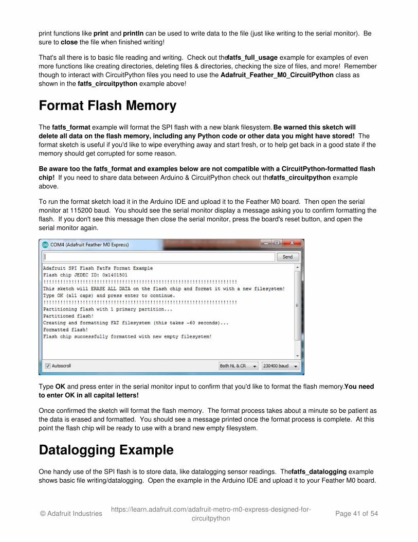
To run the format sketch load it in the Arduino IDE and upload it to the Feather M0 board. Then open the serialmonitor at 115200 baud. You should see the serial monitor display a message asking you to confirm formatting theflash. If you don't see this message then close the serial monitor, press the board's reset button, and open theserial monitor again.
Type OK and press enter in the serial monitor input to confirm that you'd like to format the flash memory. You needto enter OK in all capital letters!
Once confirmed the sketch will format the flash memory. The format process takes about a minute so be patient asthe data is erased and formatted. You should see a message printed once the format process is complete. At thispoint the flash chip will be ready to use with a brand new empty filesystem.
Datalogging ExampleOne handy use of the SPI flash is to store data, like datalogging sensor readings. The fatfs_datalogging exampleshows basic file writing/datalogging. Open the example in the Arduino IDE and upload it to your Feather M0 board.
© Adafruit Industries https://learn.adafruit.com/adafruit-metro-m0-express-designed-for-circuitpython
Page 41 of 54
Then open the serial monitor at 115200 baud. You should see a message printed every minute as the sketchwrites a new line of data to a file on the flash filesystem.
To understand how to write to a file look in the loop function of the sketch:
// Open the datalogging file for writing. The FILE_WRITE mode will open // the file for appending, i.e. it will add new data to the end of the file. File dataFile = fatfs.open(FILE_NAME, FILE_WRITE); // Check that the file opened successfully and write a line to it. if (dataFile) { // Take a new data reading from a sensor, etc. For this example just // make up a random number. int reading = random(0,100); // Write a line to the file. You can use all the same print functions // as if you're writing to the serial monitor. For example to write // two CSV (commas separated) values: dataFile.print("Sensor #1"); dataFile.print(","); dataFile.print(reading, DEC); dataFile.println(); // Finally close the file when done writing. This is smart to do to make // sure all the data is written to the file. dataFile.close(); Serial.println("Wrote new measurement to data file!"); }
Just like using the Arduino SD card library you create a File object by calling an open function and pointing it at thename of the file and how you'd like to open it (FILE_WRITE mode, i.e. writing new data to the end of the file). Notice however instead of calling open on a global SD card object you're calling it on a fatfs object created earlierin the sketch (look at the top after the #define configuration values).
Once the file is opened it's simply a matter of calling print and println functions on the file object to write data insideof it. This is just like writing data to the serial monitor and you can print out text, numeric, and other types of data. Be sure to close the file when you're done writing to ensure the data is stored correctly!
Reading and Printing FilesThe fatfs_print_file example will open a file (by default the data.csv file created by running the fatfs_dataloggingexample above) and print all of its contents to the serial monitor. Open the fatfs_print_file example and load it onyour Feather M0 board, then open the serial monitor at 115200 baud. You should see the sketch print out thecontents of data.csv (if you don't have a file called data.csv on the flash look at running the datalogging exampleabove first).
To understand how to read data from a file look in the setup function of the sketch:
// Open the file for reading and check that it was successfully opened. // The FILE_READ mode will open the file for reading. File dataFile = fatfs.open(FILE_NAME, FILE_READ); if (dataFile) { // File was opened, now print out data character by character until at the // end of the file. Serial.println("Opened file, printing contents below:"); while (dataFile.available()) { // Use the read function to read the next character. // You can alternatively use other functions like readUntil, readString, etc. // See the fatfs_full_usage example for more details. char c = dataFile.read(); Serial.print(c); } }
© Adafruit Industries https://learn.adafruit.com/adafruit-metro-m0-express-designed-for-circuitpython
Page 42 of 54

Just like when writing data with the datalogging example you create a File object by calling the open function on afatfs object. This time however you pass a file mode of FILE_READ which tells the filesystem you want to readdata.
After you open a file for reading you can easily check if data is available by calling the available function on the file,and then read a single character with the read function. This makes it easy to loop through all of the data in a fileby checking if it's available and reading a character at a time. However there are more advanced read functions youcan use too--see the fatfs_full_usage example or even the Arduino SD library documentation (http://adafru.it/ucu)(the SPI flash library implements the same functions).
Full Usage ExampleFor a more complete demonstration of reading and writing files look at the fatfs_full_usage example. Thisexamples uses every function in the library and demonstrates things like checking for the existence of a file, creatingdirectories, deleting files, deleting directories, and more.
Remember the SPI flash library is built to have the same functions and interface as the Arduino SDlibrary (http://adafru.it/ucu) so if you have code or examples that store data on a SD card they should be easy toadapt to use the SPI flash library, just create a fatfs object like in the examples above and use its open functioninstead of the global SD object's open function. Once you have a reference to a file all of the functions and usageshould be the same between the SPI flash and SD libraries!
© Adafruit Industries https://learn.adafruit.com/adafruit-metro-m0-express-designed-for-circuitpython
Page 43 of 54

Metro M0 HELP!My Metro M0 stopped working when I unplugged the USB!
A lot of our example sketches have a
while (!Serial);
line in setup(), to keep the board waiting until the USB is opened. This makes it a lot easier to debug a programbecause you get to see all the USB data output. If you want to run your Metro M0 without USB connectivity, deleteor comment out that line
My Metro never shows up as a COM or Serial port in the Arduino IDE
A vast number of Metro 'failures' are due to charge-only USB cables
We get upwards of 5 complaints a day that turn out to be due to charge-only cables!
Use only a cable that you know is for data syncing
If you have any charge-only cables, cut them in half throw them out. We are serious! They tend to be low quality ingeneral, and will only confuse you and others later, just get a good data+charge USB cable
Ack! I "did something" and now when I plug in the Metro, it doesn't show up as a device anymore so I cant upload toit or fix it...
No problem! You can 'repair' a bad code upload easily. Note that this can happen if you set a watchdog timer orsleep mode that stops USB, or any sketch that 'crashes' your Metro
1. Turn on verbose upload in the Arduino IDE preferences2. Plug in Metro M0, it won't show up as a COM/serial port that's ok3. Open up the Blink example (Examples->Basics->Blink)4. Select the correct board in the Tools menu, e.g. Metro M0 (check your board to make sure you have the right
one selected!)5. Compile it (make sure that works)6. Click Upload to attempt to upload the code7. The IDE will print out a bunch of COM Ports as it tries to upload. During this time, double-click the reset
button, you'll see the red pulsing LED and the NeoPixel will be green that tells you its now inbootloading mode
8. The Metro will show up as the Bootloader COM/Serial port9. The IDE should see the bootloader COM/Serial port and upload properly
I can't get the Metro USB device to show up - I get "USB Device Malfunctioning" errors!
This seems to happen when people select the wrong board from the Arduino Boards menu.
If you have a Metro M0 (look on the board to read what it is you have) Make sure you select Metro M0 - do not useFeather M0 or Arduino Zero
I'm having problems with COM ports and my Metro M0
Theres two COM ports you can have with the M0, one is the user port and one is the bootloader port. They arenot the same COM port number!
© Adafruit Industries https://learn.adafruit.com/adafruit-metro-m0-express-designed-for-circuitpython
Page 44 of 54
When you upload a new user program it will come up with a user com port, particularly if you use Serial in your userprogram.
If you crash your user program, or have a program that halts or otherwise fails, the user com port candisappear.
When the user COM port disappears, Arduino will not be able to automatically start the bootloader andupload new software.
So you will need to help it by performing the click-during upload procedure to re-start the bootloader, and uploadsomething that is known working like "Blink"
I don't understand why the COM port disappears, this does not happen on my Arduino UNO!
UNO-type Arduinos have a seperate serial port chip (aka "FTDI chip" or "Prolific PL2303" etc etc) which handles allserial port capability seperately than the main chip. This way if the main chip fails, you can always use the COMport.
M0 and 32u4-based Arduinos do not have a seperate chip, instead the main processor performs this task for you. Itallows for a lower cost, higher power setup...but requires a little more effort since you will need to 'kick' into thebootloader manually once in a while
I'm trying to upload to my 32u4, getting "avrdude: butterfly_recv(): programmer is not responding" errors
This is likely because the bootloader is not kicking in and you are accidentally trying to upload to the wrong COMport
The best solution is what is detailed above: manually upload Blink or a similar working sketch by hand by manuallylaunching the bootloader
I'm trying to upload to my Metro M0, and I get this error "Connecting to programmer: .avrdude: butterfly_recv():programmer is not responding"
You probably don't have Metro M0 selected in the boards drop-down. Make sure you selected Metro M0.
I'm trying to upload to my Metro and i get this error "avrdude: ser_recv(): programmer is not responding"
You probably don't have Metro M0 selected in the boards drop-down. Make sure you selected Metro M0
© Adafruit Industries https://learn.adafruit.com/adafruit-metro-m0-express-designed-for-circuitpython
Page 45 of 54
CircuitPython Setup
CircuitPython is a derivative of MicroPython designed to simplify experimentation and education on low-costmicrocontrollers. It makes it easier than ever to get prototyping by requiring no upfront desktop software downloads.Simply download CircuitPython and drag it onto the drive that appears (only available on Express boards currently).Once installed, simply copy and edit files on the drive to iterate.
DownloadingThe latest builds of CircuitPython are available from the GitHub release page. Binaries for different boards are listedunder the Downloads section. Pick the one that matches your board such as adafruit-circuitpython-feather_m0_express-
0.9.3.bin for the Feather M0 Express or adafruit-circuitpython-metro_m0_express-0.9.3.bin for the Metro M0 Express.
Files that end with .bin can be flashed with esptool.py or bossac. Files ending in .uf2 can be flashed onto a virtual drivewhen in bootloader mode.
Click here to see the latest CircuitPython Releaseshttp://adafru.it/vlF
You will see a list of all available flavors of CircuitPython. Since we support a lot of different hardware, we have along list of available downloads!
See below for which file to download!
© Adafruit Industries https://learn.adafruit.com/adafruit-metro-m0-express-designed-for-circuitpython
Page 46 of 54
FlashingFlashing is the process of updating the CircuitPython core. It isn't needed for updating your own code. There aretwo available methods: UF2 and bossac UF2 flashing is only available on Express boards, they have a UF2-capable beta bootloader. Flashing via bossac is possible with both the Express bootloader and the original"Arduino" one. We recommend using UF2 if you can. If UF2 fails, or is not available, try bossac.
Regardless of what method you use, you must first get the board into the bootloader mode. This is done by doubleclicking the reset button. The board is in bootloader mode when the red led fades in and out. Boards with the statusneopixel will also show USB status while the red led fades. Green means USB worked while red means the boardcouldn't talk to the computer. The first step to troubleshooting a red neopixel is trying a different USB cable to makesure its not a charge-only cable.
Flashing UF2Adafruit Express boards come with a new beta bootloader called UF2 that makes flashing CircuitPython even easierthan before. This beta bootloader allows you to drag so-called ".uf2" type files onto the BOOT drive. For moreinformation, check out our UF2 bootloader page. (http://adafru.it/vQd)
Start by double-clicking the reset button while it is plugged into your computer. You should see a new disk drive 'popup' called METROBOOT or FEATHERBOOT or similar, and the NeoPixel on your board glow green.
The drive will contain a few files. If you want to make a 'backup' of the current firmware on the device, drag-off andsave the CURRENT.UF2 file. Other that that you can ignore the index.htm and info_uf2.txt files. They cannot bedeleted and are only for informational purposes.
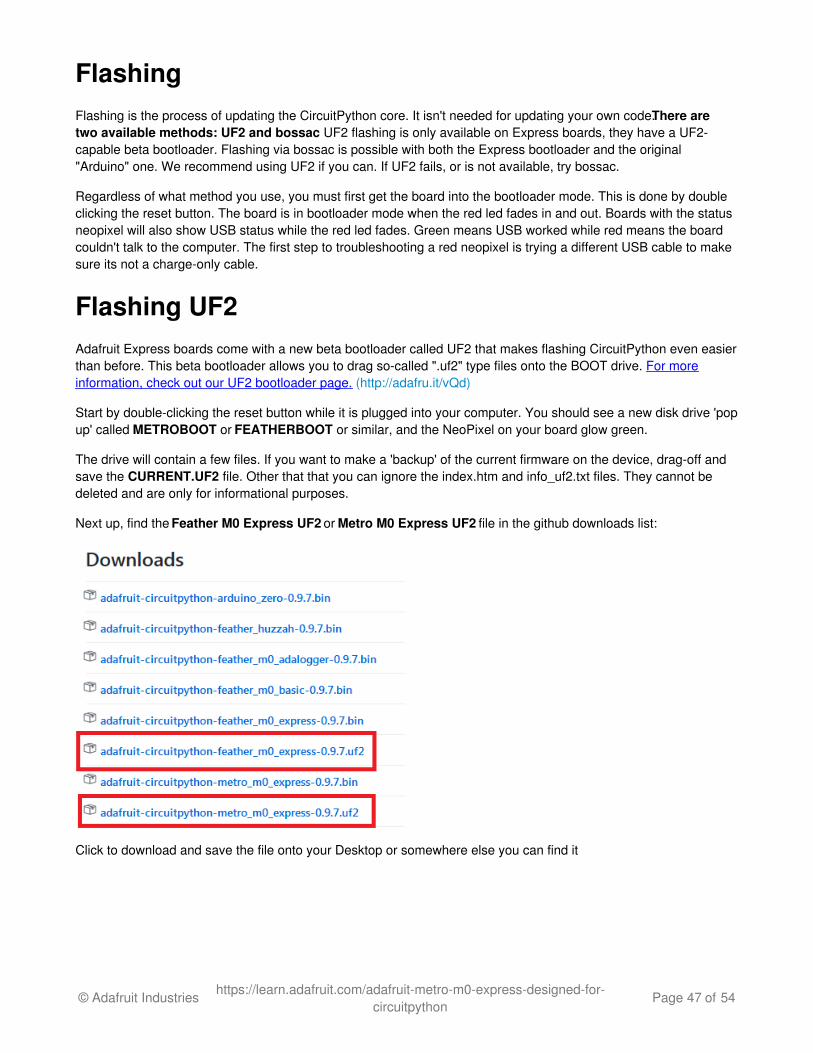
Next up, find the Feather M0 Express UF2 or Metro M0 Express UF2 file in the github downloads list:
Click to download and save the file onto your Desktop or somewhere else you can find it
© Adafruit Industries https://learn.adafruit.com/adafruit-metro-m0-express-designed-for-circuitpython
Page 47 of 54
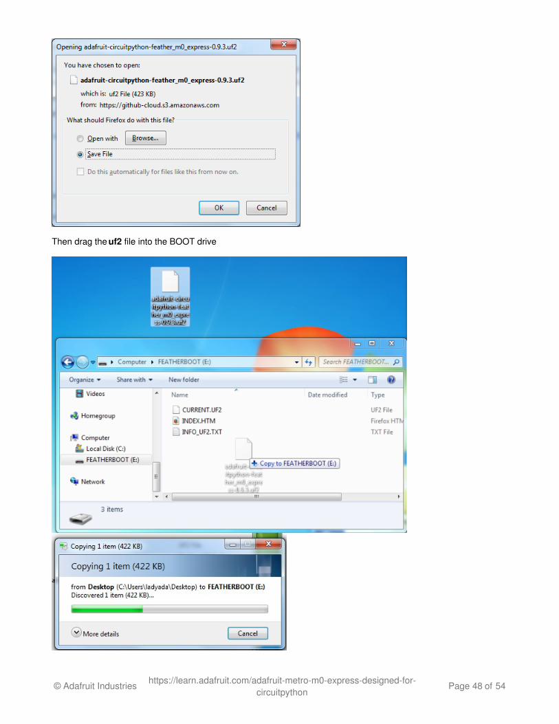
Then drag the uf2 file into the BOOT drive
© Adafruit Industries https://learn.adafruit.com/adafruit-metro-m0-express-designed-for-circuitpython
Page 48 of 54
Once the full file has been received, the board will automatically restart into CircuitPython. Your computer may warnabout ejecting the drive early, if it does, simply ignore it because the board made sure the file was received ok.
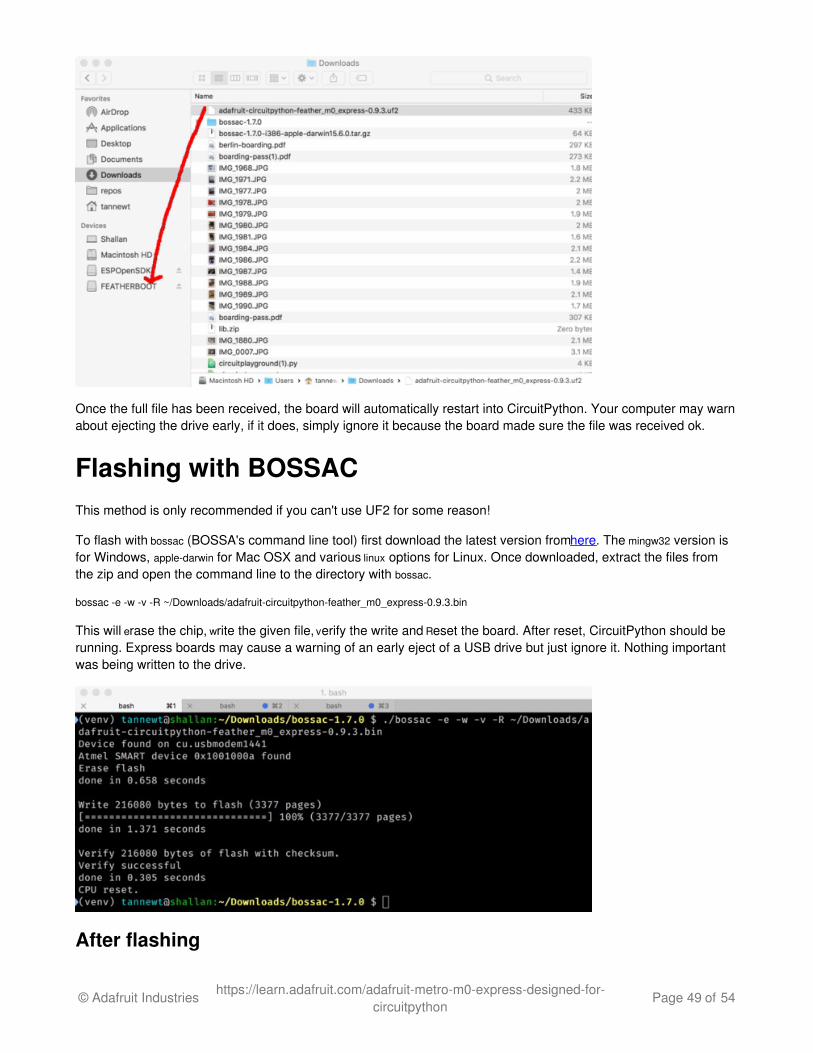
Flashing with BOSSACThis method is only recommended if you can't use UF2 for some reason!
To flash with bossac (BOSSA's command line tool) first download the latest version from here. The mingw32 version isfor Windows, apple-darwin for Mac OSX and various linux options for Linux. Once downloaded, extract the files fromthe zip and open the command line to the directory with bossac.
bossac -e -w -v -R ~/Downloads/adafruit-circuitpython-feather_m0_express-0.9.3.bin
This will erase the chip, write the given file, verify the write and Reset the board. After reset, CircuitPython should berunning. Express boards may cause a warning of an early eject of a USB drive but just ignore it. Nothing importantwas being written to the drive.
After flashing
© Adafruit Industries https://learn.adafruit.com/adafruit-metro-m0-express-designed-for-circuitpython
Page 49 of 54
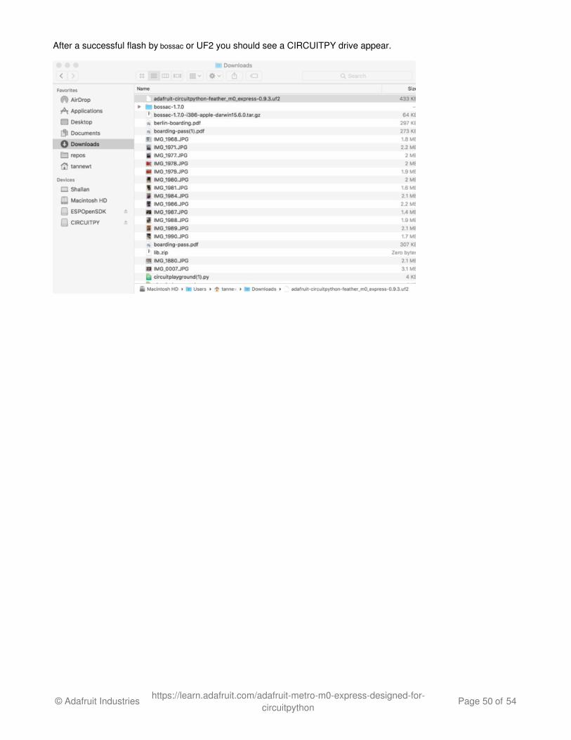
After a successful flash by bossac or UF2 you should see a CIRCUITPY drive appear.
© Adafruit Industries https://learn.adafruit.com/adafruit-metro-m0-express-designed-for-circuitpython
Page 50 of 54
CircuitPython BlinkyLet's get blinky going with CircuitPython to explore the way we can write code and confirm everything is working asexpected.
code.py
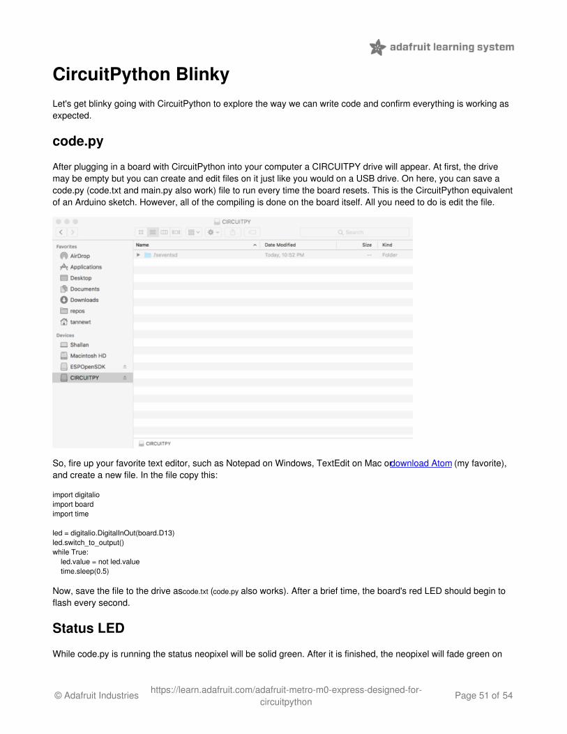
After plugging in a board with CircuitPython into your computer a CIRCUITPY drive will appear. At first, the drivemay be empty but you can create and edit files on it just like you would on a USB drive. On here, you can save acode.py (code.txt and main.py also work) file to run every time the board resets. This is the CircuitPython equivalentof an Arduino sketch. However, all of the compiling is done on the board itself. All you need to do is edit the file.
So, fire up your favorite text editor, such as Notepad on Windows, TextEdit on Mac or download Atom (my favorite),and create a new file. In the file copy this:
import digitalioimport boardimport time
led = digitalio.DigitalInOut(board.D13)led.switch_to_output()while True: led.value = not led.value time.sleep(0.5)
Now, save the file to the drive as code.txt (code.py also works). After a brief time, the board's red LED should begin toflash every second.
Status LED
While code.py is running the status neopixel will be solid green. After it is finished, the neopixel will fade green on
© Adafruit Industries https://learn.adafruit.com/adafruit-metro-m0-express-designed-for-circuitpython
Page 51 of 54
success or flash an error code on failure. Red flashes happen when data is written to the drive.
Debugging
Did the status LED flash a bunch of colors at you? You may have an error in your code. Don't worry it happens toeveryone. Python code is checked when you run it rather than before like Arduino does when it compiles. To seethe CircuitPython error you'll need to connect to the serial output (like Arduino's serial monitor).
See this guide for detailed instructions.
If you are new to Python try googling the error first, if that doesn't find an answer feel free to drop by the supportforum.
Libraries
Using libraries with CircuitPython is also super easy. Simply drag and drop libraries onto the CIRCUITPY drive orinto a lib folder on the drive to keep it tidy.
Find CircuitPython libraries on GitHub using the topic and through our tutorials.
Make sure the libraries are for CircuitPython and not MicroPython. There are some differences that may cause it tonot work as expected.
More infoGuides and TutorialsAPI ReferenceAdafruit forumLibraries
© Adafruit Industries https://learn.adafruit.com/adafruit-metro-m0-express-designed-for-circuitpython
Page 52 of 54
Downloads
DatasheetsATSAMD21 Datasheet (http://adafru.it/kUf) (the main chip on the Metro M0)Fritzing object in the Adafruit Fritzing Library (http://adafru.it/aP3)
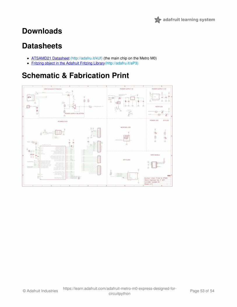
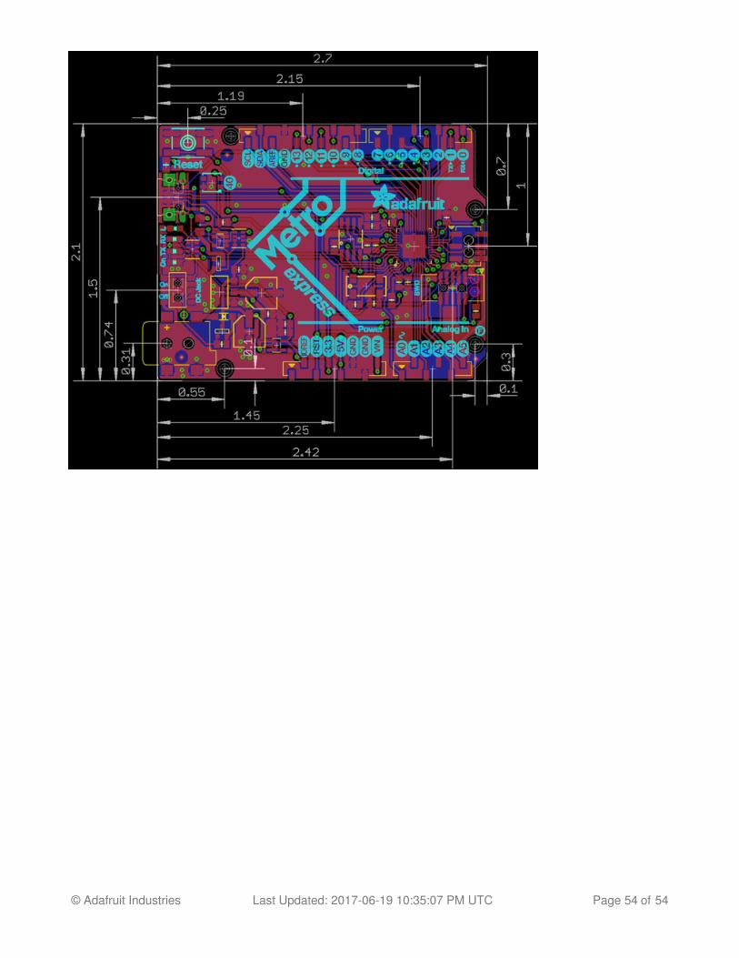
Schematic & Fabrication Print
© Adafruit Industries https://learn.adafruit.com/adafruit-metro-m0-express-designed-for-circuitpython
Page 53 of 54
© Adafruit Industries Last Updated: 2017-06-19 10:35:07 PM UTC Page 54 of 54