Embed Size (px)
Citation preview

Adafruit LED BackpacksCreated by lady ada
Last updated on 2017-09-08 07:40:11 PM UTC

248
12
1519
2222272727
2829303233343538
4247474848
5155
575859636569
Guide Contents
Guide ContentsOverview1.2" 8x8 Matrix
(http://adafru.it/aPT)Mini 8x8 Matrix Software
0.8" 8x8 MatrixMini 8x8 Matrix Software
0.54" AlphanumericAttaching the BackpackAttaching Header
Prepare the header strip:Add the Backpack:
Downloading the Arduino LibraryWiring!Load DemoLibrary ReferenceASCII dataWriting Data0.56" 7-Segment Backpack
Seven-Segment Backpack Firmware
1.2" 7-segment BackpackArduino Wiring - R3 and laterArduino Due and Other 3.3v ProcessorsArduino "Classic" WiringSeven-Segment Backpack Firmware
Bi-Color 8x8 MatrixBi-Color 8x8 LED Backpack Firmware
SchematicBi-Color 24 BargraphAttaching the bar-graph modulesSoldering on breadboard pinsBi-Color Bargraph LED Backpack Wiring & FirmwareConnecting Multiple Backpacks
© Adafruit Industries https://learn.adafruit.com/adafruit-led-backpack Page 2 of 88

70707272
7375767676767880828384858687
Wire it UpConfigure the AddressChanging I2C Address
Changing Addresses
Changing the address in your codeF.A.Q.DownloadsSoftwareFilesHT16K33 8x16 LED Backpack Breakout8x8 0.8" LED Backpack8x8 1.2" LED Backpack8x8 1.2" Bi-Color LED Backpack16x8 1.2" LED BackpacksQuad 0.56" 7-SegmentQuad 0.54" 14-segment AlphanumericQuad 1.2" 7-SegmentBicolor 24-Bargraph
© Adafruit Industries https://learn.adafruit.com/adafruit-led-backpack Page 3 of 88
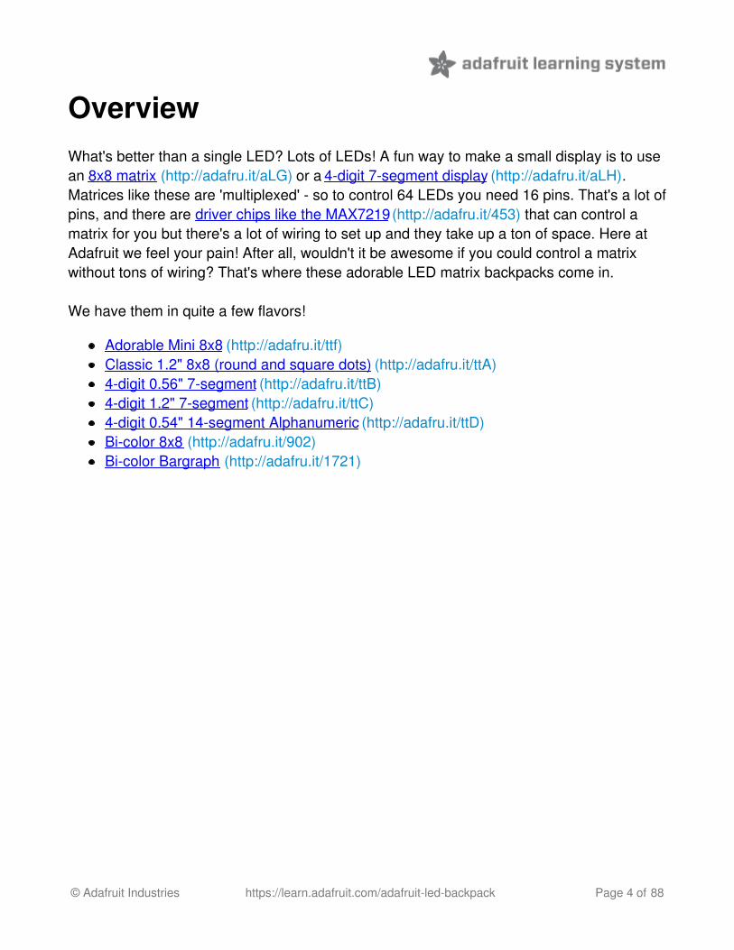
OverviewWhat's better than a single LED? Lots of LEDs! A fun way to make a small display is to usean 8x8 matrix (http://adafru.it/aLG) or a 4-digit 7-segment display (http://adafru.it/aLH).Matrices like these are 'multiplexed' - so to control 64 LEDs you need 16 pins. That's a lot ofpins, and there are driver chips like the MAX7219 (http://adafru.it/453) that can control amatrix for you but there's a lot of wiring to set up and they take up a ton of space. Here atAdafruit we feel your pain! After all, wouldn't it be awesome if you could control a matrixwithout tons of wiring? That's where these adorable LED matrix backpacks come in.
We have them in quite a few flavors!
Adorable Mini 8x8 (http://adafru.it/ttf)Classic 1.2" 8x8 (round and square dots) (http://adafru.it/ttA)4-digit 0.56" 7-segment (http://adafru.it/ttB)4-digit 1.2" 7-segment (http://adafru.it/ttC)4-digit 0.54" 14-segment Alphanumeric (http://adafru.it/ttD)Bi-color 8x8 (http://adafru.it/902)Bi-color Bargraph (http://adafru.it/1721)
© Adafruit Industries https://learn.adafruit.com/adafruit-led-backpack Page 4 of 88

© Adafruit Industries https://learn.adafruit.com/adafruit-led-backpack Page 5 of 88

© Adafruit Industries https://learn.adafruit.com/adafruit-led-backpack Page 6 of 88

The matrices use a driver chip that does all the heavy lifting for you: They have a built inclock so they multiplex the display. They use constant-current drivers for ultra-bright,consistant color (the images above are photographed at the dimmest setting to avoidoverloading our camera!), 1/16 step display dimming, all via a simple I2C interface. Thebackpacks come with address-selection jumpers so you can connect up to four mini 8x8'sor eight 7-segments (or a combination, such as four mini 8x8's and four 7-segments, etc) ona single I2C bus.
The product kit comes with a fully tested and assembled LED backpack, a 4-pin header andthe matrix of your choice. A bit of soldering is required to attach the matrix onto thebackpack but its very easy to do and only takes about 5 minutes.
Of course, in classic Adafruit fashion, we also have a detailed tutorial showing you how tosolder, wire and control the display. We even wrote a very nice library for the backpacks soyou can get running in under half an hour, displaying images on the matrix or numbers onthe 7-segment. If you've been eyeing matrix displays but hesitated because of thecomplexity, his is the solution you've been looking for!
© Adafruit Industries https://learn.adafruit.com/adafruit-led-backpack Page 7 of 88

1.2" 8x8 MatrixThis version of the LED backpack is designed for the 1.2" 8x8 matrices. They measure only1.2"x1.2" so its a shame to use a massive array of chips to control it. This backpack solvesthe annoyance of using 16 pins or a bunch of chips by having an I2C constant-currentmatrix controller sit neatly on the back of the PCB. The controller chip takes care ofeverything, drawing all 64 LEDs in the background. All you have to do is write data to itusing the 2-pin I2C interface. There are two address select pins so you can select one of 8addresses to control up to 8 of these on a single 2-pin I2C bus (as well as whatever otherI2C chips or sensors you like). The driver chip can 'dim' the entire display from 1/16brightness up to full brightness in 1/16th steps. It cannot dim individual LEDs, only the entiredisplay at once.These instruction apply to the 1.2" Matrix only! If you have a Bi-Color or 0.8" square matrix,follow the links on the left side of the page.
When you buy a pack fromAdafruit, it comes with the fullytested and assembled backpackas well as a 8x8 matrix in one ofthe colors we provide (say, red,yellow or green). You'll need tosolder the matrix onto thebackpack but its an easy task.
WATCH OUT! THE MATRIX
© Adafruit Industries https://learn.adafruit.com/adafruit-led-backpack Page 8 of 88

MUST BE INSTALLED THERIGHT WAY!
First look for the line of text onthe side of the LED matrix
WATCH OUT! THE MATRIXMUST BE INSTALLED THERIGHT WAY!
Find the corner of the backpackwith a filled in dot. Make sure thatthe text on the side of the matrixis on the same side as the filleddot
WATCH OUT! THE MATRIXMUST BE INSTALLED THERIGHT WAY!
Slide the matrix into thebackpack and flip it over. Triplecheck that the text is on thesame side as the From Adafruittext
© Adafruit Industries https://learn.adafruit.com/adafruit-led-backpack Page 9 of 88

Solder in all 16 pins
Then clip the matrix leads short
© Adafruit Industries https://learn.adafruit.com/adafruit-led-backpack Page 10 of 88

Now you're ready to wire it up toa microcontroller. We'll assumeyou want to use a 4pin header.You can also of course solderwires directly. Place a 4-pin pieceof header with the LONG pinsdown into the breadboard.
© Adafruit Industries https://learn.adafruit.com/adafruit-led-backpack Page 11 of 88

Place the soldered backpack ontop of the header.
Solder the four pins
That's it! now you're ready to run the firmware!
(http://adafru.it/aPT)Mini 8x8 Matrix Software
We wrote a basic library to help you work with the mini 8x8 matrix backpack. The library iswritten for the Arduino and will work with any Arduino as it just uses the I2C pins. The codeis very portable and can be easily adapted to any I2C-capable micro.
Wiring to the matrix is really easy
Connect CLK to the I2C clock - on Arduino UNO thats Analog #5, on the Leonardo itsDigital #3, on the Mega its digital #21Connect DAT to the I2C data - on Arduino UNO thats Analog #4, on the Leonardo itsDigital #2, on the Mega its digital #20Connect GND to common groundConnect VCC+ to power - 5V is best but 3V also seems to work for 3Vmicrocontrollers.
Next, download the Adafruit LED Backpack library from github (http://adafru.it/aLI) . Todownload click the DOWNLOADS button in the top right corner, rename the uncompressedfolder Adafruit_LEDBackpack. Check that the Adafruit_LEDBackpack foldercontains Adafruit_LEDBackpack.cpp and Adafruit_LEDBackpack.h Placethe Adafruit_LEDBackpack library folder your arduinosketchfolder/libraries/ folder. Youmay need to create the libraries subfolder if its your first library. You'll also need todownload the Adafruit GFX library (http://adafru.it/aJa) that provides the graphics drawingroutines. Restart the IDE.
© Adafruit Industries https://learn.adafruit.com/adafruit-led-backpack Page 12 of 88

Once you've restarted you should be able to select the File->Examples->Adafruit_LEDBackpack->matrix88 example sketch. Upload it to your Arduino as usual.You should see a basic test program that goes through a bunch of different drawing routine
Once you're happy that the matrix works, you can write your own sketches. The 8x8 matrixsupports everything the Adafruit GFX library - drawing pixels, lines, rectancles, circles,triangles, roundrects, and small bitmaps. For more details check out the GFX page whichwill detail all of the GFX routines (http://adafru.it/aPx).
All the drawing routines only change the display memory kept by the Arduino. Don't forgetto call writeDisplay() after drawing to 'save' the memory out to the matrix via I2C.
There are also a few small routines that are special to the matrix:
setBrightness(brighness)- will let you change the overall brightness of the entiredisplay. 0 is least bright, 15 is brightest and is what is initialized by the display whenyou start. You can call this function at any time to change the brightness of the -entire- display
© Adafruit Industries https://learn.adafruit.com/adafruit-led-backpack Page 13 of 88

blinkRate(rate) - You can blink the entire display. 0 is no blinking. 1, 2 or 3 is fordisplay blinking.You can call this function at any time to change the blink rate of the -entire- display
The default orientation forgraphics commands on thisdisplay places pixel (0,0) at thetop-left when the header is at theleft and Adafruit logo at the right.To use the matrix as shownabove (header at top, logo atbottom), callmatrix.setRotation(3) beforeissuing graphics commands.
© Adafruit Industries https://learn.adafruit.com/adafruit-led-backpack Page 14 of 88

0.8" 8x8 MatrixThis version of the LED backpack is designed for these very cute miniature 8x8 matrices.They measure only 0.8"x0.8" so its a shame to use a massive array of chips to control it.This backpack solves the annoyance of using 16 pins or a bunch of chips by having an I2Cconstant-current matrix controller sit neatly on the back of the PCB. The controller chiptakes care of everything, drawing all 64 LEDs in the background. All you have to do is writedata to it using the 2-pin I2C interface. There are two address select pins so you can selectone of 4 addresses to control up to 4 of these on a single 2-pin I2C bus (as well aswhatever other I2C chips or sensors you like). The driver chip can 'dim' the entire displayfrom 1/16 brightness up to full brightness in 1/16th steps. It cannot dim individual LEDs,only the entire display at once.
These instruction apply to the 0.8" Matrix only! If you have a Bi-Color or 1.2" square matrix,follow the links on the left side of the page.
When you buy a pack fromAdafruit, it comes with the fullytested and assembled backpackas well as a 8x8 matrix in one ofthe colors we provide (say, red,yellow or green). You'll need tosolder the matrix onto thebackpack but its an easy task.
Remove the parts frompackaging and place the LED
© Adafruit Industries https://learn.adafruit.com/adafruit-led-backpack Page 15 of 88

matrix OVER the silkscreen side.It can go 'either way' - the matrixis symmetric so as long as it goesonto the front it will work in anyorientation. Do not solder thematrix over the chip on the backof the backpack - it will not workthen!
Turn the backpack over so itssitting flat on the matrix.
Solder all 16 pins.
© Adafruit Industries https://learn.adafruit.com/adafruit-led-backpack Page 16 of 88

Clip the long pins.
Now you're ready to wire it up toa microcontroller. We'll assume
© Adafruit Industries https://learn.adafruit.com/adafruit-led-backpack Page 17 of 88
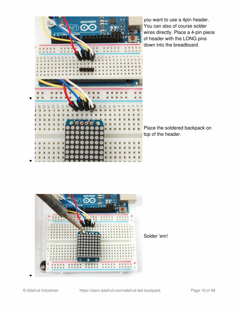
you want to use a 4pin header.You can also of course solderwires directly. Place a 4-pin pieceof header with the LONG pinsdown into the breadboard.
Place the soldered backpack ontop of the header.
Solder 'em!
© Adafruit Industries https://learn.adafruit.com/adafruit-led-backpack Page 18 of 88

That's it! now you're ready to run the firmware!
Mini 8x8 Matrix Software
We wrote a basic library to help you work with the mini 8x8 matrix backpack. The library iswritten for the Arduino and will work with any Arduino as it just uses the I2C pins. The codeis very portable and can be easily adapted to any I2C-capable micro.
Wiring to the matrix is really easy
Connect CLK to the I2C clock - on Arduino UNO thats Analog #5, on the Leonardo itsDigital #3, on the Mega its digital #21Connect DAT to the I2C data - on Arduino UNO thats Analog #4, on the Leonardo itsDigital #2, on the Mega its digital #20Connect GND to common groundConnect VCC+ to power - 5V is best but 3V also seems to work for 3Vmicrocontrollers.
Next, download the Adafruit LED Backpack library from github (http://adafru.it/aLI) . Todownload click the DOWNLOADS button in the top right corner, rename the uncompressedfolder Adafruit_LEDBackpack. Check that the Adafruit_LEDBackpack foldercontains Adafruit_LEDBackpack.cpp and Adafruit_LEDBackpack.h Placethe Adafruit_LEDBackpack library folder your arduinosketchfolder/libraries/ folder. Youmay need to create the libraries subfolder if its your first library.
You'll also need to download the Adafruit GFX library (http://adafru.it/aJa) that provides thegraphics drawing routines. Follow the same instructions as above, but with Adafruit_GFXinstead of Adafruit_LEDBackpack.
Restart the IDE.
Once you've restarted you should be able to select the File->Examples->Adafruit_LEDBackpack->matrix88 example sketch. Upload it to your Arduino as usual.You should see a basic test program that goes through a bunch of different drawingroutines
© Adafruit Industries https://learn.adafruit.com/adafruit-led-backpack Page 19 of 88

Once you're happy that the matrix works, you can write your own sketches. The 8x8 matrixsupports everything the Adafruit GFX library - drawing pixels, lines, rectancles, circles,triangles, roundrects, and small bitmaps. For more details check out the GFX page whichwill detail all of the GFX routines (http://adafru.it/aPx).
All the drawing routines only change the display memory kept by the Arduino. Don't forgetto call writeDisplay() after drawing to 'save' the memory out to the matrix via I2C.
There are also a few small routines that are special to the matrix:
setBrightness(brighness)- will let you change the overall brightness of the entiredisplay. 0 is least bright, 15 is brightest and is what is initialized by the display whenyou startblinkRate(rate) - You can blink the entire display. 0 is no blinking. 1, 2 or 3 is fordisplay blinking.
© Adafruit Industries https://learn.adafruit.com/adafruit-led-backpack Page 20 of 88

The default orientation forgraphics commands on thisdisplay places pixel (0,0) at thetop-left when the header is at thetop and Adafruit logo at thebottom. matrix.setRotation() canbe used to use the display inother orientations.
© Adafruit Industries https://learn.adafruit.com/adafruit-led-backpack Page 21 of 88

0.54" Alphanumeric
(http://adafru.it/l3c)
This version of the LED backpack is designed for two dual 14-segment "Alphanumeric"displays. These 14-segment displays normally require 18 pins (4 'characters' and 14 totalsegments each) This backpack solves the annoyance of using 18 pins or a bunch of chipsby having an I2C constant-current matrix controller sit neatly on the back of the PCB. Thecontroller chip takes care of everything, drawing all the LEDs in the background. All youhave to do is write data to it using the 2-pin I2C interface.
There are three address select pins so you can select one of 8 addresses to control up to 8of these on a single 2-pin I2C bus (as well as whatever other I2C chips or sensors you like).The driver chip can 'dim' the entire display from 1/16 brightness up to full brightness in1/16th steps. It cannot dim individual LEDs, only the entire display at once.
Attaching the Backpack
When you buy a pack fromAdafruit, it comes with the fullytested and assembled backpackas well as two dual 14-segmentdisplay in one of the colors weprovide (say, red, yellow, blue orgreen). You'll need to solder thematrix onto the backpack but it'san easy task.
Remove the parts from
© Adafruit Industries https://learn.adafruit.com/adafruit-led-backpack Page 22 of 88

packaging and place the LEDmatrices OVER the silkscreenside. DO NOT PUT THEDISPLAY ON UPSIDE DOWNOR IT WONT WORK!! Checkthe image below to make surethe 'decimal point' dots are onthe bottom, matching thesilkscreen.
Turn the backpack over so it issitting flat on the matrix.
© Adafruit Industries https://learn.adafruit.com/adafruit-led-backpack Page 23 of 88

Solder all of the pins!
© Adafruit Industries https://learn.adafruit.com/adafruit-led-backpack Page 24 of 88

© Adafruit Industries https://learn.adafruit.com/adafruit-led-backpack Page 25 of 88

Clip the long pins.
© Adafruit Industries https://learn.adafruit.com/adafruit-led-backpack Page 26 of 88

Check your work, making sureeach pin is nicely soldered, andthere's no cold solder joints orshorted pins
Attaching Header
Prepare the headerstrip:
Cut the strip to length ifnecessary. It will be easier tosolder if you insert it into abreadboard - long pins down
© Adafruit Industries https://learn.adafruit.com/adafruit-led-backpack Page 27 of 88

Add the Backpack:
Place the backpack board overthe pins so that the short pinspoke through the breakout pads
Solder all 5 pins!
That's it! now you're ready to run the firmware on your Arduino!
Downloading the Arduino LibraryWe wrote a basic library to help you work with the alphanumeric backpack. The library iswritten for the Arduino and will work with any Arduino as it just uses the I2C pins. The codeis very portable and can be easily adapted to any I2C-capable micro.
Begin by downloading our Adafruit LED Backpack library from github (http://adafru.it/aLI).You can do that by visiting the github repo and manually downloading or, easier, just click
© Adafruit Industries https://learn.adafruit.com/adafruit-led-backpack Page 28 of 88

this button to download the zip Download LED Backpack Libraryhttp://adafru.it/dxhRename the uncompressed folder Adafruit_LEDBackpack and check that theAdafruit_LEDBackpack folder contains Adafruit_LEDBackpack.cpp andAdafruit_LEDBackpack.h
Place the Adafruit_LEDBackpack library folder your arduinosketchfolder/libraries/folder. You may need to create the libraries subfolder if its your first library. Restart the IDE.
We also have a great tutorial on Arduino library installation at:http://learn.adafruit.com/adafruit-all-about-arduino-libraries-install-use (http://adafru.it/aYM)You'll also need to download the Adafruit GFX library - even though this particularbackpack doesn't use it! Its just one of those Arduino dependencies! You can grab theAdafruit GFX library from github (http://adafru.it/aJa) or download by clicking below.Download Adafruit GFX Libraryhttp://adafru.it/cBBRename the uncompressed folder Adafruit_GFX and check that the Adafruit_GFX foldercontains Adafruit_GFX.cpp and Adafruit_GFX.h
Place the Adafruit_GFX library folder your arduinosketchfolder/libraries/ folder like youdid with the LED backpacks
Wiring!Nex up, let's wire it up to an Arduino. We'll be using an Arduino.
Connect CLK to the I2C clock - on Arduino UNO thats Analog #5, on the Leonardo it'sDigital #3, on the Mega it's digital #21Connect DAT to the I2C data - on Arduino UNO thats Analog #4, on the Leonardo it'sDigital #2, on the Mega it's digital #20Connect GND to common groundConnect VCC+ to power - 5V is best but 3V will work if that's all you've got (it will bedimmer)Connect Vi2c to your microcontroller's logic level (3-5V) - If you're using an Arduino,this is almost certainly 5V. If its a 3V Arduino such as a Due, connect it to 3V
Both Vi2c and Vcc MUST be connected to 3 to 5VDC! Vcc is for the LED driver power,Vi2c is what sets the logic level for communication to the chip.
© Adafruit Industries https://learn.adafruit.com/adafruit-led-backpack Page 29 of 88

Load DemoRestart the Arduino IDE and load up the File->Adafruit_LEDBackpack->quadalphanumdemo
© Adafruit Industries https://learn.adafruit.com/adafruit-led-backpack Page 30 of 88

Upload to your Arduino, and open up the Serial console at 9600 baud speed. You'll seeeach digit light up all the segments, then the display will scroll through the 'font table'showing every character that it knows how to display. Finally, you'll get a notice to starttyping into the serial console. Type a message and hit return, you'll see it scroll onto thedisplay!
© Adafruit Industries https://learn.adafruit.com/adafruit-led-backpack Page 31 of 88

Library ReferenceFor the quad displays, we have a special object that can handle ascii data for easy printing.
© Adafruit Industries https://learn.adafruit.com/adafruit-led-backpack Page 32 of 88

You can create the object with
Adafruit_AlphaNum4 alpha4 = Adafruit_AlphaNum4();
There's no arguments or pins because the backpacks use the fixed I2C pins.By default, the address is 0x70, but you can pass in the I2C address used when youinitialize the display with begin
alpha4.begin(0x70); // pass in the address
Next up, the segments can be turned on/off for each digit by writing the 'raw' bitmap youwant, for example, all the LEDs off on digit #3 is
alpha4.writeDigitRaw(3, 0x0);
All the segments on for digit #0 is
alpha4.writeDigitRaw(0, 0x3FFF);
This is the segment map:
the 16 bit digit you pass in for raw image has this mapping:
0 DP N M L K J H G2 G1 F E D C B A
The first bit isn't used, you can make it 0 or 1
To turn on just the A segment, use 0x0001To turn on just the G1 segment, use 0x0040
ASCII data
© Adafruit Industries https://learn.adafruit.com/adafruit-led-backpack Page 33 of 88

If you're just looking to print 'text' you can use our font table, just pass in an ASCIIcharacter!
For example, to set digit #0 to A call:
alpha4.writeDigitAscii(0, 'A')
Writing DataDon't forget to 'write' the data to the display with
alpha4.writeDisplay();
That's what actually 'sets' the data onto the LEDs!
© Adafruit Industries https://learn.adafruit.com/adafruit-led-backpack Page 34 of 88

0.56" 7-Segment BackpackThis version of the LED backpack is designed for these big bright 7-segment displays.These 7-segment displays normally require 13 pins (5 'characters' and 8 total segmentseach) This backpack solves the annoyance of using 13 pins or a bunch of chips by havingan I2C constant-current matrix controller sit neatly on the back of the PCB. The controllerchip takes care of everything, drawing all the LEDs in the background. All you have to do iswrite data to it using the 2-pin I2C interface. There are three address select pins so you canselect one of 8 addresses to control up to 8 of these on a single 2-pin I2C bus (as well aswhatever other I2C chips or sensors you like). The driver chip can 'dim' the entire displayfrom 1/16 brightness up to full brightness in 1/16th steps. It cannot dim individual LEDs,only the entire display at once.
When you buy a pack fromAdafruit, it comes with the fullytested and assembled backpackas well as a 7-segment display inone of the colors we provide(say, red, yellow, blue or green).You'll need to solder the matrixonto the backpack but it's aneasy task.
Remove the parts frompackaging and place the LEDmatrix OVER the silkscreen
© Adafruit Industries https://learn.adafruit.com/adafruit-led-backpack Page 35 of 88

side. DO NOT PUT THEDISPLAY ON UPSIDE DOWNOR IT WONT WORK!! Checkthe image below to make surethe 'decimal point' dots are onthe bottom, matching thesilkscreen.
Turn the backpack over so it issitting flat on the matrix.
Solder all 14 pins.
© Adafruit Industries https://learn.adafruit.com/adafruit-led-backpack Page 36 of 88

Clip the long pins.
© Adafruit Industries https://learn.adafruit.com/adafruit-led-backpack Page 37 of 88

Now you're ready to wire it up toa microcontroller. We'll assumeyou want to use a 4pin header.You can also of course solderwires directly. Place a 4-pin pieceof header with the LONG pinsdown into the breadboard.
Place the soldered backpack ontop of the header and Solder 'em!
That's it! now you're ready to run the firmware!
Seven-Segment Backpack Firmware
We wrote a basic library to help you work with the 7-segment backpack. The library iswritten for the Arduino and will work with any Arduino as it just uses the I2C pins. The codeis very portable and can be easily adapted to any I2C-capable micro.
Wiring to the matrix is really easy
© Adafruit Industries https://learn.adafruit.com/adafruit-led-backpack Page 38 of 88

Connect CLK to the I2C clock - on Arduino UNO thats Analog #5, on the Leonardo it'sDigital #3, on the Mega it's digital #21Connect DAT to the I2C data - on Arduino UNO thats Analog #4, on the Leonardo it'sDigital #2, on the Mega it's digital #20Connect GND to common groundConnect VCC+ to power - 5V is best but 3V also seems to work for 3Vmicrocontrollers.
Next, download the Adafruit LED Backpack library from github (http://adafru.it/aLI) . Todownload click the DOWNLOADS button in the top right corner, rename the uncompressedfolder Adafruit_LEDBackpack. Check that the Adafruit_LEDBackpack folder containsAdafruit_LEDBackpack.cpp and Adafruit_LEDBackpack.h Place theAdafruit_LEDBackpack library folder your arduinosketchfolder/libraries/ folder. You mayneed to create the libraries subfolder if it's your first library. You'll also need to download theAdafruit GFX library (http://adafru.it/aJa) - rename it Adafruit_GFX and install it as the LEDbackpack library. It's not actually used for the 7-segment, it's only for the matrix backpacksbut it's still required. Restart the IDE.
Once you've restarted you should be able to select the File?Examples?Adafruit_LEDBackpack?sevenseg example sketch. Upload it to your Arduino as usual.You should see a basic test program that goes through a bunch of different routines.
© Adafruit Industries https://learn.adafruit.com/adafruit-led-backpack Page 39 of 88

Once you're happy that the matrix works, you can write your own sketches.
There's a few ways you can draw to the display. The easiest is to just call print - just likeyou do with Serial
print(variable,HEX) - this will print a hexidecimal number, from 0000 up to FFFFprint(variable,DEC) or print(variable) - this will print a decimal integer, from 0000 upto 9999
If you need more control, you can call writeDigitNum(location, number) - this will write thenumber (0-9) to a single location. Location #0 is all the way to the left, location #2 is thecolon dots so you probably want to skip it, location #4 is all the way to the right. If you wanta decimal point, call writeDigitNum(location, number, true) which will paint the decimalpoint. To draw the colon, usedrawColon(true or false)
If you want even more control, you can call writeDigitRaw(location,bitmask) to draw a raw8-bit mask (as stored in a uint8_t) to that location.
All the drawing routines only change the display memory kept by the Arduino. Don't forget
© Adafruit Industries https://learn.adafruit.com/adafruit-led-backpack Page 40 of 88

to call writeDisplay() after drawing to 'save' the memory out to the matrix via I2C.
There are also a few small routines that are special to the backpack:
setBrightness(brightness)- will let you change the overall brightness of the entiredisplay. 0 is least bright, 15 is brightest and is what is initialized by the display whenyou startblinkRate(rate) - You can blink the entire display. 0 is no blinking. 1, 2 or 3 is fordisplay blinking.
© Adafruit Industries https://learn.adafruit.com/adafruit-led-backpack Page 41 of 88

1.2" 7-segment BackpackThese backpacks drive the massive 1.2" 7-segment modules. With 2 leds per segmentthese make a gorgeous and impressive display. The 7-segment displays normally require16 pins to drive. This backpack uses an I2C constant-current matrix controller on the backof the PCB, so you only need 2 pins to drive it!
The controller chip takes care of multiplexing all the LEDs in the background. All you haveto do is write data to it using the 2-pin I2C interface. There are three address select pins soyou can select one of 8 addresses to control up to 8 of these on a single 2-pin I2C bus (aswell as whatever other I2C chips or sensors you like). The driver chip can 'dim' the entiredisplay from 1/16 brightness up to full brightness in 1/16th steps. It cannot dim individualLEDs, only the entire display at once.
When you buy a pack fromAdafruit, it comes with the fullytested and assembled backpackas well as a 7-segment display inone of the colors we provide(say, red, yellow, blue or green).You'll need to solder the matrixonto the backpack but its an easytask.
Remove the parts frompackaging and place the LEDmatrix OVER the silkscreen side.DO NOT PUT THE DISPLAY ONUPSIDE DOWN OR IT WONTWORK!! Check the imagebelow to make sure the'decimal point' dots are in thesame location as the ones onthe silkscreen.
© Adafruit Industries https://learn.adafruit.com/adafruit-led-backpack Page 42 of 88

Turn the backpack over so itssitting flat on the matrix andready to solder.
© Adafruit Industries https://learn.adafruit.com/adafruit-led-backpack Page 43 of 88

Then solder each pin. There are8 on each end for a total of 16.
That completes the basic assembly. For use on a breadboard, you will want to also install a5-pin header on the edge of the board.
© Adafruit Industries https://learn.adafruit.com/adafruit-led-backpack Page 44 of 88

Clip the long pins close to theboard.
Cut the header strip to length ifnecessary and insert LONG pinsdown into the breadboard.
© Adafruit Industries https://learn.adafruit.com/adafruit-led-backpack Page 45 of 88

Then solder all 5 pins.
Now you are ready to wire it to your microcontroller. The required connections are:
"D" - I2C Data Pin (SDA)"C" - I2C Clock Pin (SCL)"+" - 5v. (Will not run on 3.3v!)"-" - GND"IO" - I2C bus voltage.
Due to the size of this display, there are 2 LEDs in series for each segment. Because ofthis, the display requires 5v to run. It will not run on 3.3v.
For use with 3.3v processors, connect the IO pin to 3.3v. This will keep the I2C bus signalsat a safe level for your processor.
With 5v processors like the Arduino UNO, this pin can be connected to either 5v or 3.3v.(use 3.3v if there will be other 3.3v devices on the bus)
© Adafruit Industries https://learn.adafruit.com/adafruit-led-backpack Page 46 of 88

Arduino Wiring - R3and later
Connect:
D -> SDAC -> SCL+ -> 5v- -> GNDIO -> jumper to + for 5v.
Arduino Due andOther 3.3vProcessors
Connect:
D -> SDAC -> SCL+ -> 5v- -> GNDIO -> 3.3v
Arduino "Classic"Wiring
Connect:
D -> Analog-4 or Digital 20for the MegaC -> Analog-5 or Digital 21for the Mega+ -> 5v- -> GNDIO -> jumper to + for 5v.
© Adafruit Industries https://learn.adafruit.com/adafruit-led-backpack Page 47 of 88

OK, now on to the firmware!
Seven-Segment Backpack Firmware
Our 7-segment backpack library makes it easy to program these displays. The library iswritten for the Arduino and will work with any Arduino as it just uses the I2C pins. The codeis very portable and can be easily adapted to any I2C-capable micro.
You can download the Adafruit LED Backpack library from github (http://adafru.it/aLI) . Todownload click the DOWNLOADS button in the top right corner, rename the uncompressedfolder Adafruit_LEDBackpack. Check that the Adafruit_LEDBackpack folder containsAdafruit_LEDBackpack.cpp and Adafruit_LEDBackpack.h.
If you need help with installing you libraries, we have a detailed guide here:
Installing Arduino Librarieshttp://adafru.it/aYM
You'll also need to download the Adafruit GFX library (http://adafru.it/aJa) - rename itAdafruit_GFX and install it as the LED backpack library. Close all open IDE windows andrestart the IDE.
Once you've restarted you should be able to select the File?Examples?Adafruit_LEDBackpack?sevenseg example sketch. Upload it to your Arduino as usual.You should see a "sevenseg" example sketch that will demonstrate various capabilities ofthe library and the display.
© Adafruit Industries https://learn.adafruit.com/adafruit-led-backpack Page 48 of 88

Once you're happy that the matrix works, you can write your own sketches.
There's a few ways you can draw to the display. The easiest is to just call print - just likeyou do with Serial
print(variable,HEX) - this will print a hexidecimal number, from 0000 up to FFFFprint(variable,DEC) or print(variable) - this will print a decimal integer, from 0000 upto 9999
If you need more control, you can call writeDigitNum(location, number) - this will write thenumber (0-9) to a single location. Location #0 is all the way to the left, location #2 is thecolon dots so you probably want to skip it, location #4 is all the way to the right.
To control the colon and decimal points, use the writeDigitRaw(location, bitmap) function. (Note that both dots of the center colon are wired together internal to the display, so it isnot possible to address them separately.) Specify 2 for the location and the bits aremapped as follows:
0x02 - center colon (both dots)0x04 - left colon - lower dot0x08 - left colon - upper dot0x10 - decimal point
© Adafruit Industries https://learn.adafruit.com/adafruit-led-backpack Page 49 of 88

If you want a decimal point, call writeDigitNum(location, number, true) which will paintthe decimal point. To draw the colon, use drawColon(true or false)
If you want full control of the segments in all digits, you can callwriteDigitRaw(location,bitmask) to draw a raw 8-bit mask (as stored in a uint8_t) toanylocation.
All the drawing routines only change the display memory kept by the Arduino. Don't forgetto call writeDisplay() after drawing to 'save' the memory out to the matrix via I2C.
There are also a few small routines that are special to the backpack:
setBrightness(brighness)- will let you change the overall brightness of the entiredisplay. 0 is least bright, 15 is brightest and is what is initialized by the display whenyou startblinkRate(rate) - You can blink the entire display. 0 is no blinking. 1, 2 or 3 is fordisplay blinking.
© Adafruit Industries https://learn.adafruit.com/adafruit-led-backpack Page 50 of 88

Bi-Color 8x8 MatrixThis version of the LED backpack is designed for these bright and colorful square=pixeled8x8 matrices. They have 64 red and 64 green LEDs inside, for a total of 128 LEDscontrolled as a 8x16 matrix. This backpack solves the annoyance of using 24 pins or abunch of chips by having an I2C constant-current matrix controller sit neatly on the back ofthe PCB. The controller chip takes care of everything, drawing all 128 LEDs in thebackground. All you have to do is write data to it using the 2-pin I2C interface. There arethree address select pins so you can select one of 8 addresses to control up to 8 of theseon a single 2-pin I2C bus (as well as whatever other I2C chips or sensors you like). Thedriver chip can 'dim' the entire display from 1/16 brightness up to full brightness in 1/16thsteps. It cannot dim individual LEDs, only the entire display at once.
Pay close attention to the instructions for positioning the matrix. It must be orientedcorrectly to work and is almost impossible to remove it once it has been soldered to thebackpack!
© Adafruit Industries https://learn.adafruit.com/adafruit-led-backpack Page 51 of 88

When you buy a pack fromAdafruit, it comes with the fullytested and assembled backpackas well as a 8x8 matrix. You'llneed to solder the matrix ontothe backpack but its an easytask.
Remove the parts frompackaging and place the LEDmatrix OVER the silkscreenside.
The matrix must be solderedon the correct orientation or itwill not work! Check for theside of the matrix that hasprinting on it. Then look for thefront of the PCB that has acircle instead of a square inthe corner and line those up asshown on the left
Do not solder the matrix over thechip on the back of the backpack- it will not work then!
© Adafruit Industries https://learn.adafruit.com/adafruit-led-backpack Page 52 of 88

Turn the backpack over so itssitting flat on the matrix.
Solder all 24 pins.
© Adafruit Industries https://learn.adafruit.com/adafruit-led-backpack Page 53 of 88

Clip the long pins
Now you're ready to wire it up toa microcontroller. We'll assume
© Adafruit Industries https://learn.adafruit.com/adafruit-led-backpack Page 54 of 88

you want to use a 4pin header.You can also of course solderwires directly. Place a 4-pin pieceof header with the LONG pinsdown into the breadboard.
Place the soldered backpack ontop of the header.
Solder 'em!
© Adafruit Industries https://learn.adafruit.com/adafruit-led-backpack Page 55 of 88

Bi-Color 8x8 LED Backpack Firmware
We wrote a basic library to help you work with the bi-color 8x8 matrix backpack. The libraryis written for the Arduino and will work with any Arduino as it just uses the I2C pins. Thecode is very portable and can be easily adapted to any I2C-capable micro.
Wiring to the matrix is really easy
Connect CLK to the I2C clock - on Arduino UNO thats Analog #5, on the Leonardo itsDigital #3, on the Mega its digital #21Connect DAT to the I2C data - on Arduino UNO thats Analog #4, on the Leonardo itsDigital #2, on the Mega its digital #20Connect GND to common groundConnect VCC+ to power - 5V is best but 3V also seems to work for 3Vmicrocontrollers.
Next, download the Adafruit LED Backpack library from github (http://adafru.it/aLI) . Todownload click the DOWNLOADS button in the top right corner, rename the uncompressedfolder Adafruit_LEDBackpack. Check that the Adafruit_LEDBackpack foldercontains Adafruit_LEDBackpack.cpp and Adafruit_LEDBackpack.h Placethe Adafruit_LEDBackpack library folder your arduinosketchfolder/libraries/ folder. Youmay need to create the libraries subfolder if its your first library. You'll also need todownload the Adafruit GFX library (http://adafru.it/aJa) that provides the graphics drawingroutines. Restart the IDE.
Once you've restarted you should be able to select the File->Examples->Adafruit_LEDBackpack->bicolor88 example sketch. Upload it to your Arduino as usual.You should see a basic test program that goes through a bunch of different drawingroutines
© Adafruit Industries https://learn.adafruit.com/adafruit-led-backpack Page 56 of 88

Once you're happy that the matrix works, you can write your own sketches. The 8x8 matrixsupports everything the Adafruit GFX library - drawing pixels, lines, rectangles, circles,triangles, roundrects, and small bitmaps. For more details check out the GFX page whichwill detail all of the GFX routines (http://adafru.it/aPx).
All the drawing routines only change the display memory kept by the Arduino. Don't forgetto call writeDisplay() after drawing to 'save' the memory out to the matrix via I2C.
There are also a few small routines that are special to the matrix:
setBrightness(brightness)- will let you change the overall brightness of the entiredisplay. 0 is least bright, 15 is brightest and is what is initialized by the display whenyou startblinkRate(rate) - You can blink the entire display. 0 is no blinking. 1, 2 or 3 is fordisplay blinking.
© Adafruit Industries https://learn.adafruit.com/adafruit-led-backpack Page 57 of 88

The default orientation forgraphics commands on thisdisplay places pixel (0,0) at thetop-left when the header is at theleft and Adafruit logo at the right.To use the matrix as shownabove (header at top, logo atbottom), callmatrix.setRotation(3) beforeissuing graphics commands.
Schematic
© Adafruit Industries https://learn.adafruit.com/adafruit-led-backpack Page 58 of 88
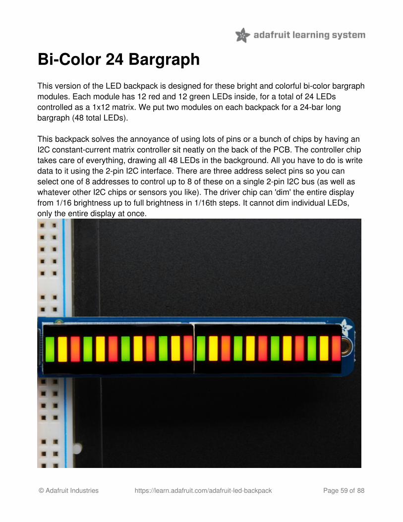
Bi-Color 24 BargraphThis version of the LED backpack is designed for these bright and colorful bi-color bargraphmodules. Each module has 12 red and 12 green LEDs inside, for a total of 24 LEDscontrolled as a 1x12 matrix. We put two modules on each backpack for a 24-bar longbargraph (48 total LEDs).
This backpack solves the annoyance of using lots of pins or a bunch of chips by having anI2C constant-current matrix controller sit neatly on the back of the PCB. The controller chiptakes care of everything, drawing all 48 LEDs in the background. All you have to do is writedata to it using the 2-pin I2C interface. There are three address select pins so you canselect one of 8 addresses to control up to 8 of these on a single 2-pin I2C bus (as well aswhatever other I2C chips or sensors you like). The driver chip can 'dim' the entire displayfrom 1/16 brightness up to full brightness in 1/16th steps. It cannot dim individual LEDs,only the entire display at once.
© Adafruit Industries https://learn.adafruit.com/adafruit-led-backpack Page 59 of 88

Attaching the bar-graph modulesPay close attention to the instructions for positioning the bargraphs. They must be orientedcorrectly to work and is almost impossible to remove them once soldered to the backpack!Remove the parts from packaging and place the LED bargraphs over the outlines on thetop of the PCB.
The bargraph must be soldered on the correct orientation or it will not work! Checkfor the side of the bargraph that has printing on it. Then look for the outline on thePCB that has "Text on this side" marked!
Do not solder the matrix onto the back of the PCB, it won't work either!
© Adafruit Industries https://learn.adafruit.com/adafruit-led-backpack Page 60 of 88

To keep the two bargraphs lined up nicely, you can use a little masking or scotch tape onthe bargraph modules, tape them so they are in a straight line. There is a little play duringsoldering so if you don't do this the two modules may not be in a perfect line.
Turn over the PCB and bendopposite-corner pins of themodules out so that the modulesare fixed in place against thePCB. Now is a good time to do alast check that you oriented themodules the right way!
© Adafruit Industries https://learn.adafruit.com/adafruit-led-backpack Page 61 of 88

Solder all the module pins in!
© Adafruit Industries https://learn.adafruit.com/adafruit-led-backpack Page 62 of 88

OK nice work!
Once soldered, clip each pin.They're quite short and the pinsare thicker than usual, so do thisover/inside a trash bin so that thepins don't fly off and it you or yourpets.
© Adafruit Industries https://learn.adafruit.com/adafruit-led-backpack Page 63 of 88

Everything should be neat andclipped, you're done!
Soldering on breadboard pins
This is an optional step - you only need to do this step if you're planning on using thebargraph in a breadboard. Chances are you may want to solder wires directly to the padsinstead, so you can mount the bargraph elsewhere. Anyhow, skip this step if its not for you!
Break off a piece of male header,4 pins long. Plug the long endsinto a solderless breadboard.
© Adafruit Industries https://learn.adafruit.com/adafruit-led-backpack Page 64 of 88

Place the PCB on top. you mayneed to support it a little since itsquite long.
Solder these 4 pins too, sinceyou're good at it now this shouldbe easy.
© Adafruit Industries https://learn.adafruit.com/adafruit-led-backpack Page 65 of 88

Bi-Color Bargraph LED Backpack Wiring& FirmwareWe wrote a basic library to help you work with the bi-color bargraph backpack. The libraryis written for the Arduino and will work with any Arduino as it just uses the I2C pins. Thecode is very portable and can be easily adapted to any I2C-capable micro.
Wiring to the bargraph is really easy
Connect SCL to the I2C clock - on Arduino UNO thats Analog #5, on the Leonardo itsDigital #3, on the Mega its digital #21Connect SDA to the I2C data - on Arduino UNO thats Analog #4, on the Leonardo itsDigital #2, on the Mega its digital #20Connect GND to common groundConnect VCC to power - 5V is best but 3V also seems to work for 3Vmicrocontrollers.
© Adafruit Industries https://learn.adafruit.com/adafruit-led-backpack Page 66 of 88

Next, download the Adafruit LED Backpack library from github (http://adafru.it/aLI) . Todownload click the DOWNLOADS button in the top right corner, rename the uncompressedfolder Adafruit_LEDBackpack. Check that the Adafruit_LEDBackpack folder containsAdafruit_LEDBackpack.cpp and Adafruit_LEDBackpack.h Place theAdafruit_LEDBackpack library folder your arduinosketchfolder/libraries/ folder. You mayneed to create the libraries subfolder if its your first library. You'll also need to download theAdafruit GFX library (http://adafru.it/aJa) that provides the graphics drawing routines.Restart the IDE.
Once you've restarted you should be able to select the File->Examples->Adafruit_LEDBackpack->bargraph24 example sketch. Upload it to your Arduino asusual. You should see a basic test program that tests all the LEDs with different colors
Using the library interface is very easy. Start by creating the object with
Adafruit_24bargraph bar = Adafruit_24bargraph();
you can name it whatever you want, not just bar
© Adafruit Industries https://learn.adafruit.com/adafruit-led-backpack Page 67 of 88

Then initialize it with
bar.begin(0x70); // pass in the address
You can init with any address from 0x70 to 0x77, just make sure you solder in the matchingsolder jumpers!
Finally, write to the bargraph with
bar.setBar(lednumber, ledcolor);
Where lednumber is 0 thru 23. ledcolor can be LED_RED, LED_YELLOW, LED_GREEN orLED_OFF
The drawing routines only change the display memory kept by the Arduino. Don't forget tocall bar.writeDisplay() after drawing to 'save' the memory out to the matrix via I2C.
There are also a few small routines that are special to the matrix:
setBrightness(brightness)- will let you change the overall brightness of the entiredisplay. 0 is least bright, 15 is brightest and is what is initialized by the display whenyou startblinkRate(rate) - You can blink the entire display. 0 is no blinking. 1, 2 or 3 is fordisplay blinking.
© Adafruit Industries https://learn.adafruit.com/adafruit-led-backpack Page 68 of 88

Connecting Multiple BackpacksThe coolest part about the I2C backpacks is that you can connect more than one using justthe same 2 pins. This opens possibilities for all kinds of multi-displayprojects (http://adafru.it/aQt).
For a project that shows this is practice, check out this page (http://adafru.it/aQF) onanimating multiple LED backpacks
© Adafruit Industries https://learn.adafruit.com/adafruit-led-backpack Page 69 of 88

Wire it UpTo connect another backpack to your project, just wire it in parallel with the first one as inthe diagram below.
Configure the AddressFor each backpack you add, you need to configure a different I2C address. You can keepadding backpacks in the same way until you run out of addresses. See the next page forhow to configure the address on your backpack.
© Adafruit Industries https://learn.adafruit.com/adafruit-led-backpack Page 70 of 88

© Adafruit Industries https://learn.adafruit.com/adafruit-led-backpack Page 71 of 88

Changing I2C AddressThe HT16K33 driver chip on these LED backpacks has a default I2C address of 0x70.Since each device on an I2C bus must have a unique address, its important to avoidcollisions or you'll get a lot of strange responses from your electronic devices!
Luckily, the HT16K33 has 2 or 3 address adjust pins, so that the address can be changed!The mini 0.8" 8x8 matrix backpack has 2 address adjust pins. The 1.2" 8x8, bi-color 8x8, bi-color bargraph and 4 x 7-segment backpacks have 3 address adjust pins.
That means that you can set the backpacks to these addresses:
Mini 0.8" 8x8: 0x70, 0x71, 0x72, 0x73Small 1.2" 8x8: 0x70, 0x71, 0x72, 0x73, 0x74, 0x75, 0x76, 0x774 x 7-segment: 0x70, 0x71, 0x72, 0x73, 0x74, 0x75, 0x76, 0x77Bi-color 1.2" 8x8: 0x70, 0x71, 0x72, 0x73, 0x74, 0x75, 0x76, 0x77Bi-color 24-bargraph: 0x70, 0x71, 0x72, 0x73, 0x74, 0x75, 0x76, 0x77
You can mix-and-match matrices, as long as each one has a unique address!
Changing Addresses
You can change the address of a backpack very easily. Look on the back to find the two orthree A0, A1 or A2 solder jumpers. Each one of these is used to hardcode in the address.If a jumper is shorted with solder, that sets the address. A0 sets the lowest bit with a valueof 1, A1 sets the middle bit with a value of 2 and A2 sets the high bit with a value of 4. Thefinal address is 0x70 + A2 + A1 + A0. So for example if A2 is shorted and A0 is shorted,the address is 0x70 + 4 + 1 = 0x75. If only A1 is shorted, the address is 0x70 + 2 = 0x72
A2 does not appear on the mini 0.8" 8x8 matrix, so you cannot set the address higher than0x73
On the 1.2" 8x8 backpacks, the labels for A1 and A2 are swapped! Sorry about that!
© Adafruit Industries https://learn.adafruit.com/adafruit-led-backpack Page 72 of 88

Changing the address in your code
Once you've adjusted the address on the backpack, you'll also want to adjust the address inthe code!
© Adafruit Industries https://learn.adafruit.com/adafruit-led-backpack Page 73 of 88

For the Arduino library we wrote, its simple. For example, lets say you want to have twoseven-segment matrices. One is set to address 0x70 and the other is set to 0x71. Find thiscode in the example
Adafruit_7segment matrix = Adafruit_7segment();
void setup() { Serial.begin(9600); Serial.println("7 Segment Backpack Test");
matrix.begin(0x70);}
And change it to this:
Adafruit_7segment matrix1 = Adafruit_7segment();Adafruit_7segment matrix2 = Adafruit_7segment();
void setup() { Serial.begin(9600); Serial.println("Double 7 Segment Backpack Test");
matrix1.begin(0x70); matrix2.begin(0x71);}
That is, instantiate two matrix objects. Then one is called with begin(0x70) and the other iscalled with begin(0x71). Each one can be used individually. If you need more matrices, justinstantiate more objects at the top and begin() each one with the unique i2c address.
© Adafruit Industries https://learn.adafruit.com/adafruit-led-backpack Page 74 of 88

F.A.Q.I want to use these modules with other non-Arduino, how can I port the code?The best way to get up and running is to read the HT16K33 driver datasheet available athttp://learn.adafruit.com/adafruit-led-backpack/downloads (http://adafru.it/aMx) - thebackpacks all use this chip to do all the LED driving. You can cross-reference thisdocument with the Arduino library code to adapt it to your platform. Any microcontroller thathas I2C host support should be able to drive the backpacks but we only provide Arduinoexample code at this time
I'd like to use these backpacks with Python / Linux (e.g. a Raspberry Pi)You're in luck! We have a full tutorial here that covers using the 7-segment and 8x8matrices on a Pi with Python code -> http://learn.adafruit.com/matrix-7-segment-led-backpack-with-the-raspberry-pi (http://adafru.it/aPj)
I am having strange problems when combining Adafruit Motor Shield/Servo Shield(PCA9685 based) with the Adafruit LED Matrix/7Seg BackpacksWe are not sure why this occurs but there is an address collision even though the addressare different! Set the backpacks to address 0x71 or anything other than the default 0x70 tomake the issue go away
© Adafruit Industries https://learn.adafruit.com/adafruit-led-backpack Page 75 of 88

Downloads
SoftwareDownload the Adafruit LED Backpack library from github (http://adafru.it/aLI) - This codeprovides support for the mini 8x8, 1.2" 8x8, 7-segment, bargraph, alphanumeric and bicolorLED matrix backpacks.
To download click the ZIP download button, rename the uncompressed folderAdafruit_LEDBackpack. Check that the Adafruit_LEDBackpack folder containsAdafruit_LEDBackpack.cpp and Adafruit_LEDBackpack.h Place theAdafruit_LEDBackpack library folder your arduinosketchfolder/libraries/ folder.
You may need to create the libraries subfolder if its your first library.
You'll also need to download the Adafruit GFX library (http://adafru.it/aJa) - its not actuallyused for the 7-segment, its only for the matrix backpacks but its still required. Install just likethe library above. Restart the IDE
FilesFritzing objects in Adafruit Fritzing library (http://adafru.it/aP3)EagleCAD PCB files for all backpacks in GitHub (http://adafru.it/aLJ)
The backpacks all use the HT16K33 chip solely for LED driving (http://adafru.it/aMy) -the mini 8x8's use the 24 pin version and the others use the 28 pin vesion
HT16K33 8x16 LED Backpack BreakoutSchematic & fabrication print
© Adafruit Industries https://learn.adafruit.com/adafruit-led-backpack Page 76 of 88

© Adafruit Industries https://learn.adafruit.com/adafruit-led-backpack Page 77 of 88

8x8 0.8" LED Backpack
© Adafruit Industries https://learn.adafruit.com/adafruit-led-backpack Page 78 of 88

© Adafruit Industries https://learn.adafruit.com/adafruit-led-backpack Page 79 of 88

8x8 1.2" LED Backpack
© Adafruit Industries https://learn.adafruit.com/adafruit-led-backpack Page 80 of 88

© Adafruit Industries https://learn.adafruit.com/adafruit-led-backpack Page 81 of 88

8x8 1.2" Bi-Color LED Backpack
© Adafruit Industries https://learn.adafruit.com/adafruit-led-backpack Page 82 of 88

16x8 1.2" LED Backpacks
© Adafruit Industries https://learn.adafruit.com/adafruit-led-backpack Page 83 of 88
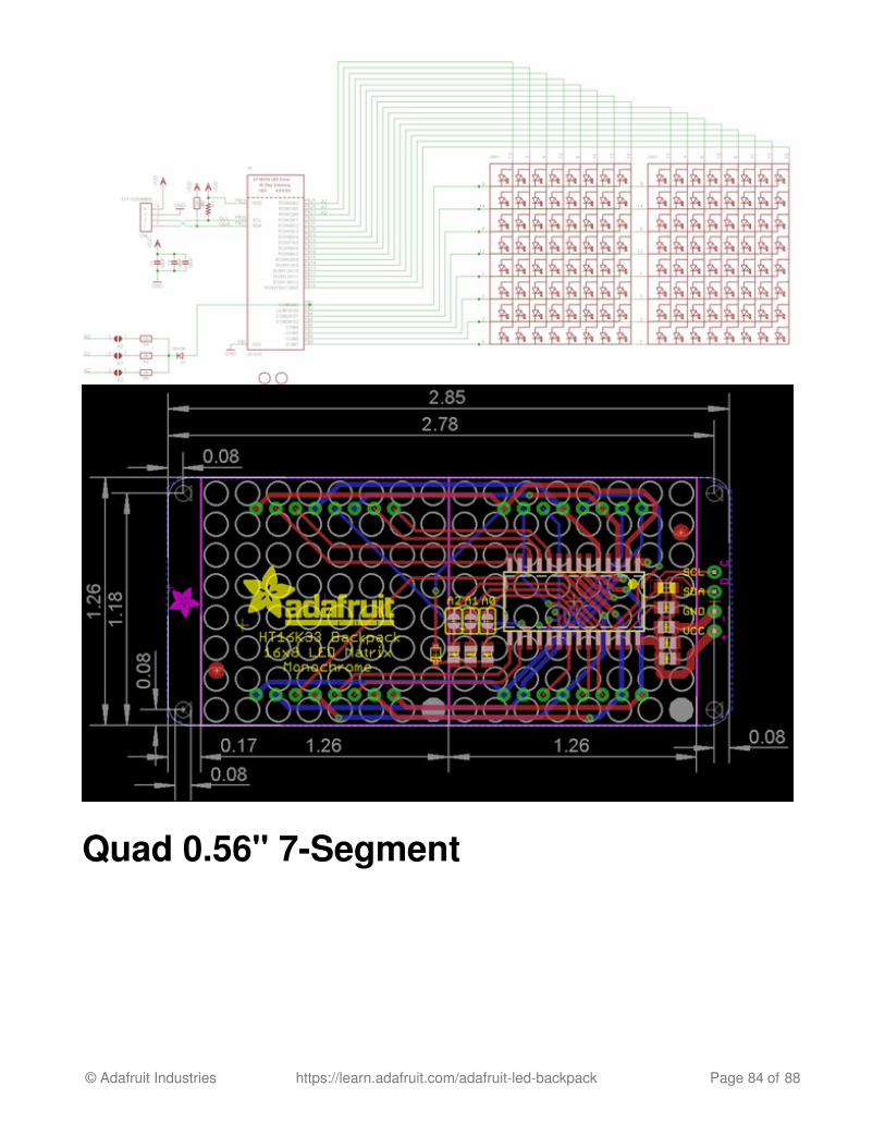
Quad 0.56" 7-Segment
© Adafruit Industries https://learn.adafruit.com/adafruit-led-backpack Page 84 of 88

Quad 0.54" 14-segment Alphanumeric
© Adafruit Industries https://learn.adafruit.com/adafruit-led-backpack Page 85 of 88

Quad 1.2" 7-Segment
© Adafruit Industries https://learn.adafruit.com/adafruit-led-backpack Page 86 of 88

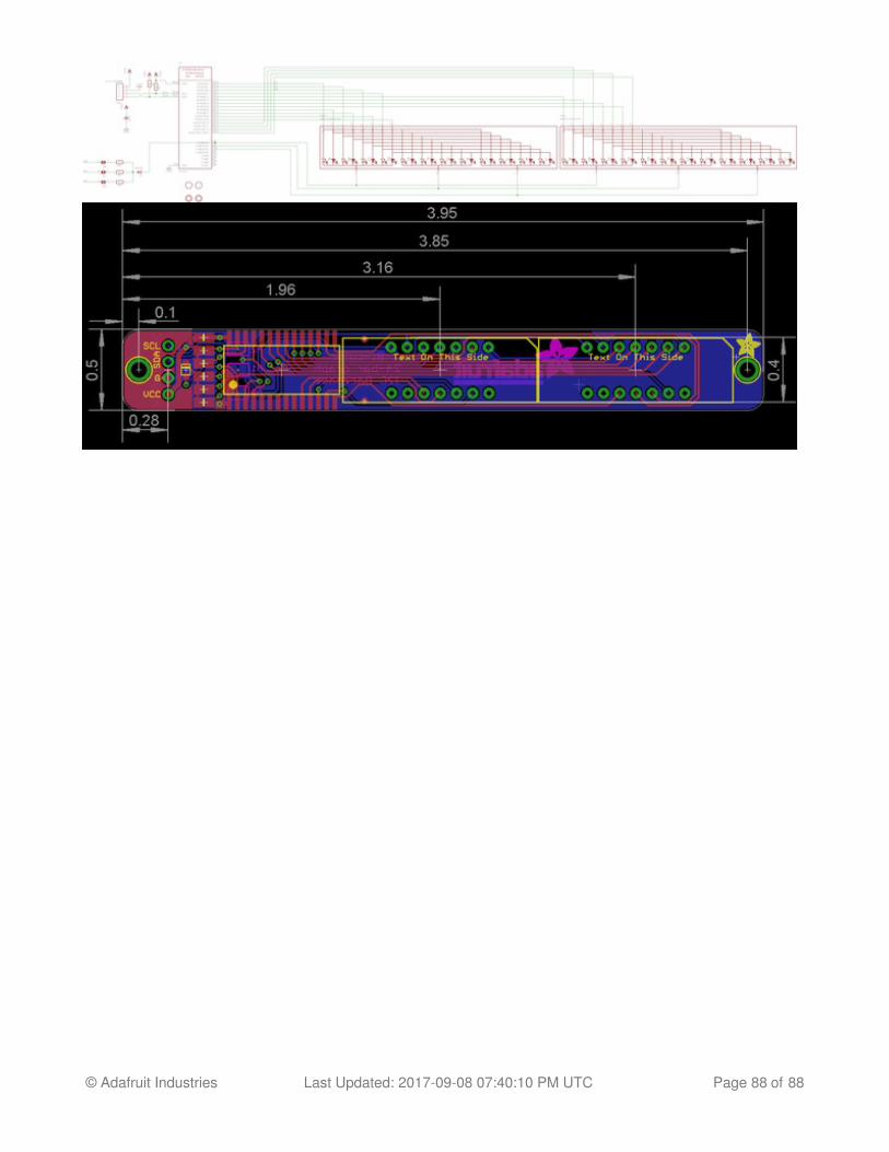
Bicolor 24-Bargraph
© Adafruit Industries https://learn.adafruit.com/adafruit-led-backpack Page 87 of 88
© Adafruit Industries Last Updated: 2017-09-08 07:40:10 PM UTC Page 88 of 88