Embed Size (px)
Citation preview
Adafruit I2C FRAM BreakoutCreated by lady ada
Last updated on 2017-07-14 05:38:45 AM UTC
23666
8889
1111121314161616
Guide Contents
Guide ContentsOverviewPinouts
Power Pins:I2C Logic pins:
AssemblyPrepare the header strip:Add the breakout board:And Solder!
Wiring and TestArduino WiringDownload Adafruit_FRAM_I2CLoad DemoLibrary ReferenceDownloadsSchematicsFabrication Print
© Adafruit Industries https://learn.adafruit.com/adafruit-i2c-fram-breakout Page 2 of 17
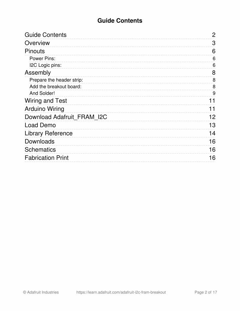
Overview
You're probably familiar with SRAM, DRAM, EEPROM and Flash but what about FRAM?FRAM is 'ferroelectric' RAM, which has some very interesting and useful properties. UnlikeSRAM, FRAM does not lose the data when power is lost. In that sense it's a durablestorage memory chip like Flash. However, it is much faster than Flash - and you don't haveto deal with writing or erasing pages.
© Adafruit Industries https://learn.adafruit.com/adafruit-i2c-fram-breakout Page 3 of 17
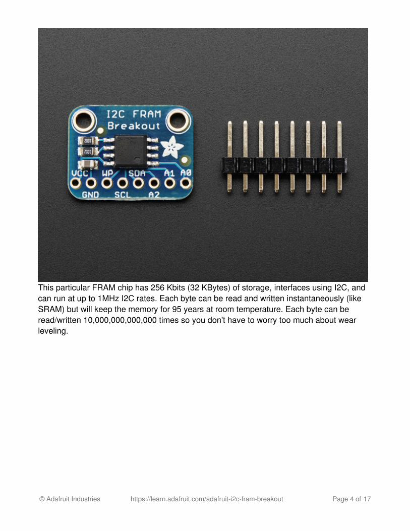
This particular FRAM chip has 256 Kbits (32 KBytes) of storage, interfaces using I2C, andcan run at up to 1MHz I2C rates. Each byte can be read and written instantaneously (likeSRAM) but will keep the memory for 95 years at room temperature. Each byte can beread/written 10,000,000,000,000 times so you don't have to worry too much about wearleveling.
© Adafruit Industries https://learn.adafruit.com/adafruit-i2c-fram-breakout Page 4 of 17
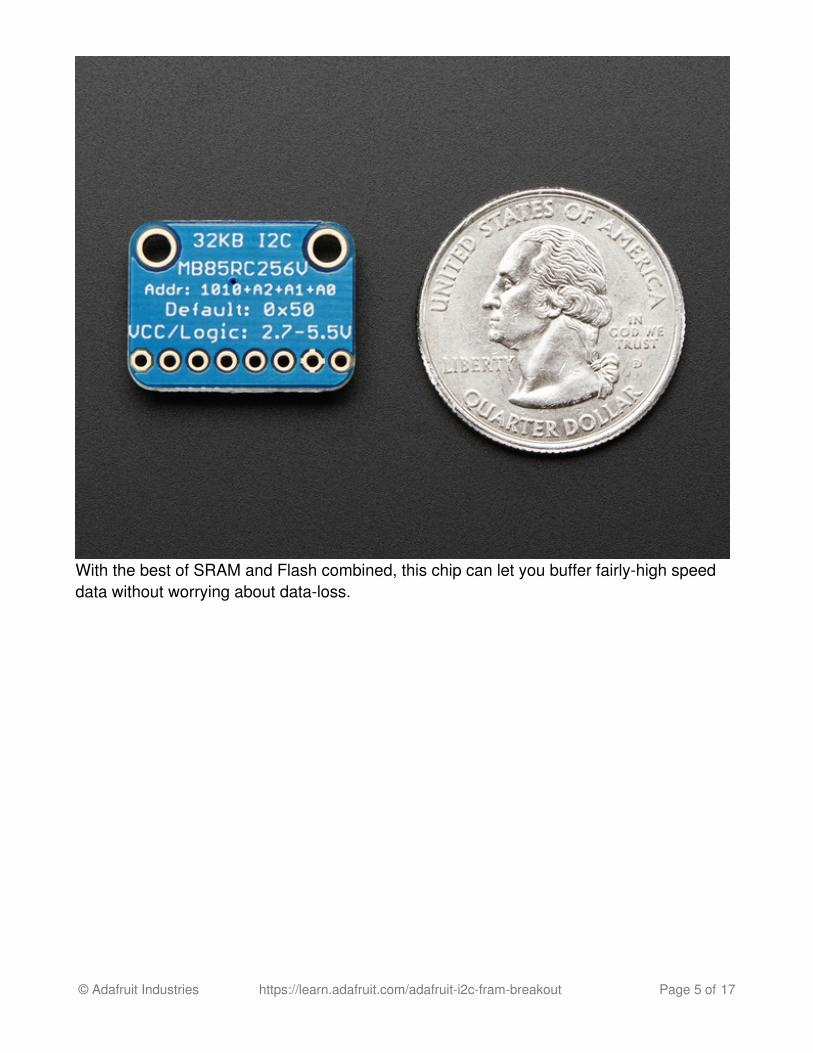
With the best of SRAM and Flash combined, this chip can let you buffer fairly-high speeddata without worrying about data-loss.
© Adafruit Industries https://learn.adafruit.com/adafruit-i2c-fram-breakout Page 5 of 17
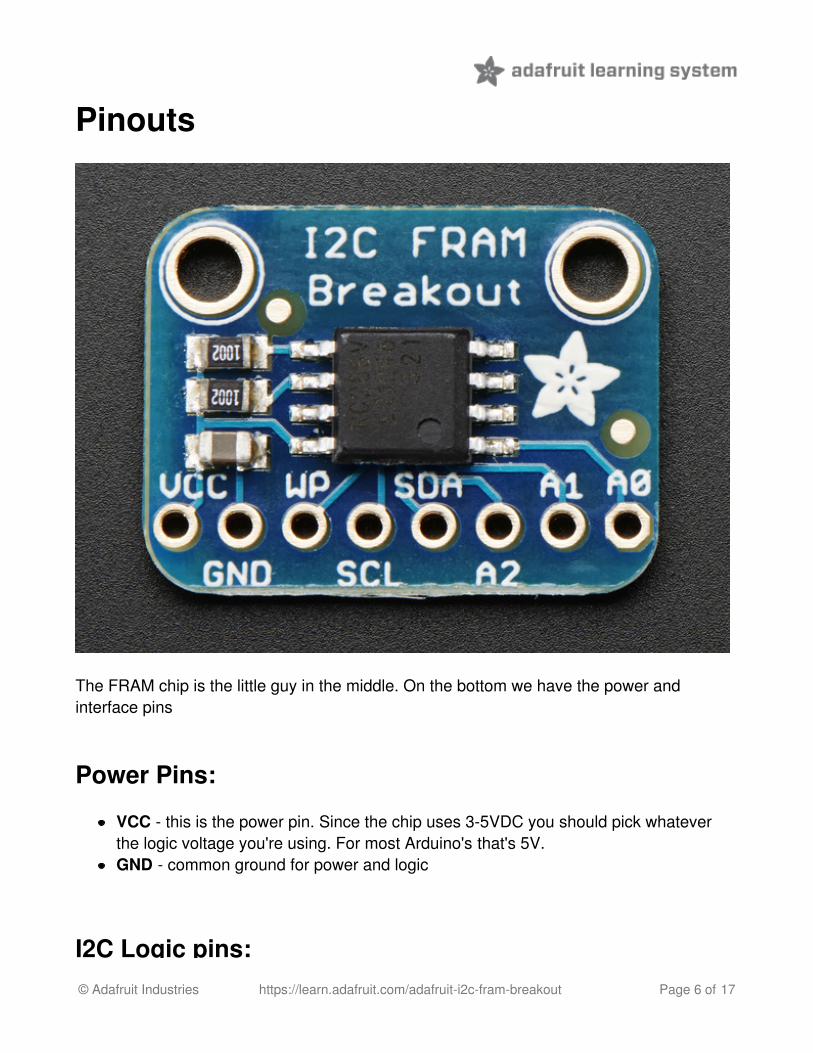
Pinouts
The FRAM chip is the little guy in the middle. On the bottom we have the power andinterface pins
Power Pins:
VCC - this is the power pin. Since the chip uses 3-5VDC you should pick whateverthe logic voltage you're using. For most Arduino's that's 5V.GND - common ground for power and logic
I2C Logic pins:© Adafruit Industries https://learn.adafruit.com/adafruit-i2c-fram-breakout Page 6 of 17
I2C Logic pins:
WP - Write Protect pin. This is used to force write protection so you cannot write tothe FRAM. It has an internal pulldown. Bring to a high voltage (VCC) to turn on WPSCL - I2C clock pin, connect to your microcontrollers I2C clock line.SDA - I2C data pin, connect to your microcontrollers I2C data line.A2, A1, A0 - These are the I2C address selection pins. By default the I2C address is0x50. Connecting these pins to VCC and power cycling the chip will adjust the lowerthree bits of the address. For example, if A0 is high, the address is 0x51. If A1 and A2are high, the address is 0x56
© Adafruit Industries https://learn.adafruit.com/adafruit-i2c-fram-breakout Page 7 of 17
Assembly
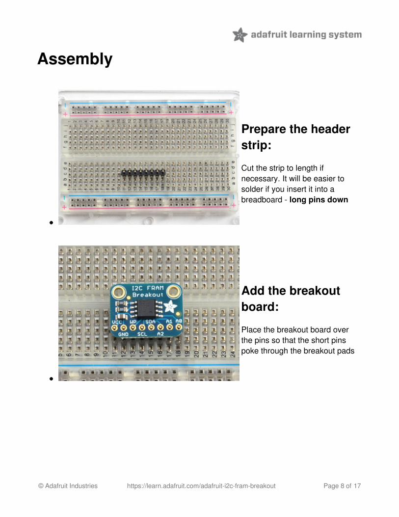
Prepare the headerstrip:
Cut the strip to length ifnecessary. It will be easier tosolder if you insert it into abreadboard - long pins down
Add the breakoutboard:
Place the breakout board overthe pins so that the short pinspoke through the breakout pads
© Adafruit Industries https://learn.adafruit.com/adafruit-i2c-fram-breakout Page 8 of 17
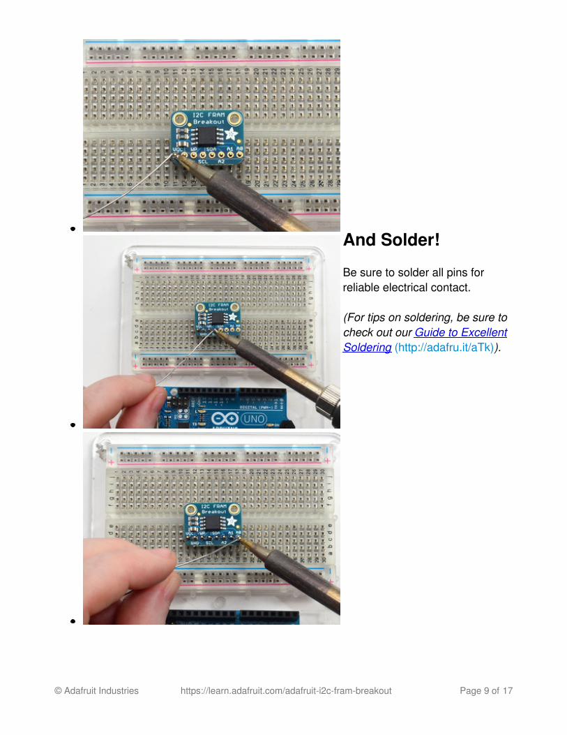
And Solder!
Be sure to solder all pins forreliable electrical contact.
(For tips on soldering, be sure tocheck out our Guide to ExcellentSoldering (http://adafru.it/aTk)).
© Adafruit Industries https://learn.adafruit.com/adafruit-i2c-fram-breakout Page 9 of 17
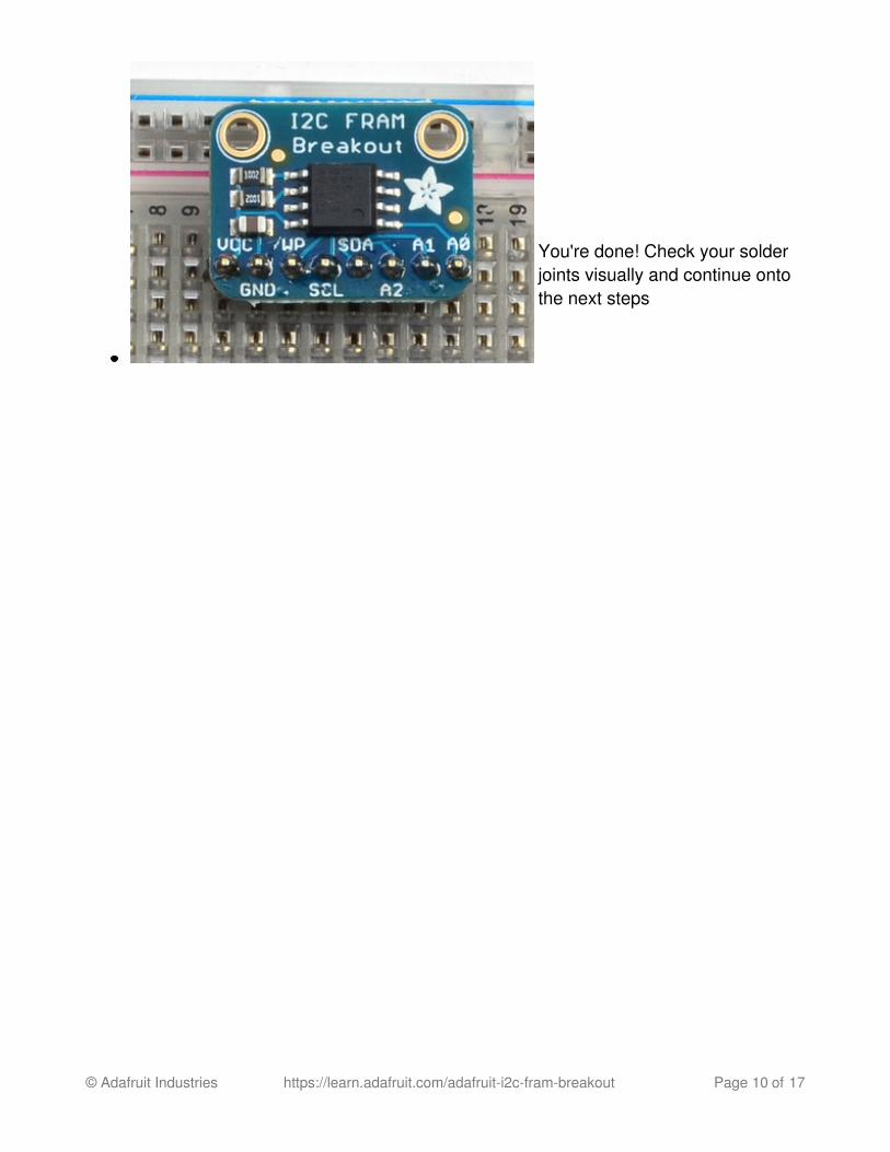
You're done! Check your solderjoints visually and continue ontothe next steps
© Adafruit Industries https://learn.adafruit.com/adafruit-i2c-fram-breakout Page 10 of 17
Wiring and Test
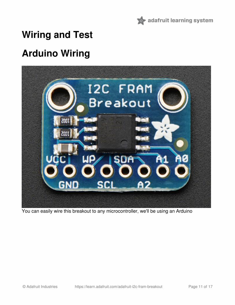
Arduino Wiring
You can easily wire this breakout to any microcontroller, we'll be using an Arduino
© Adafruit Industries https://learn.adafruit.com/adafruit-i2c-fram-breakout Page 11 of 17
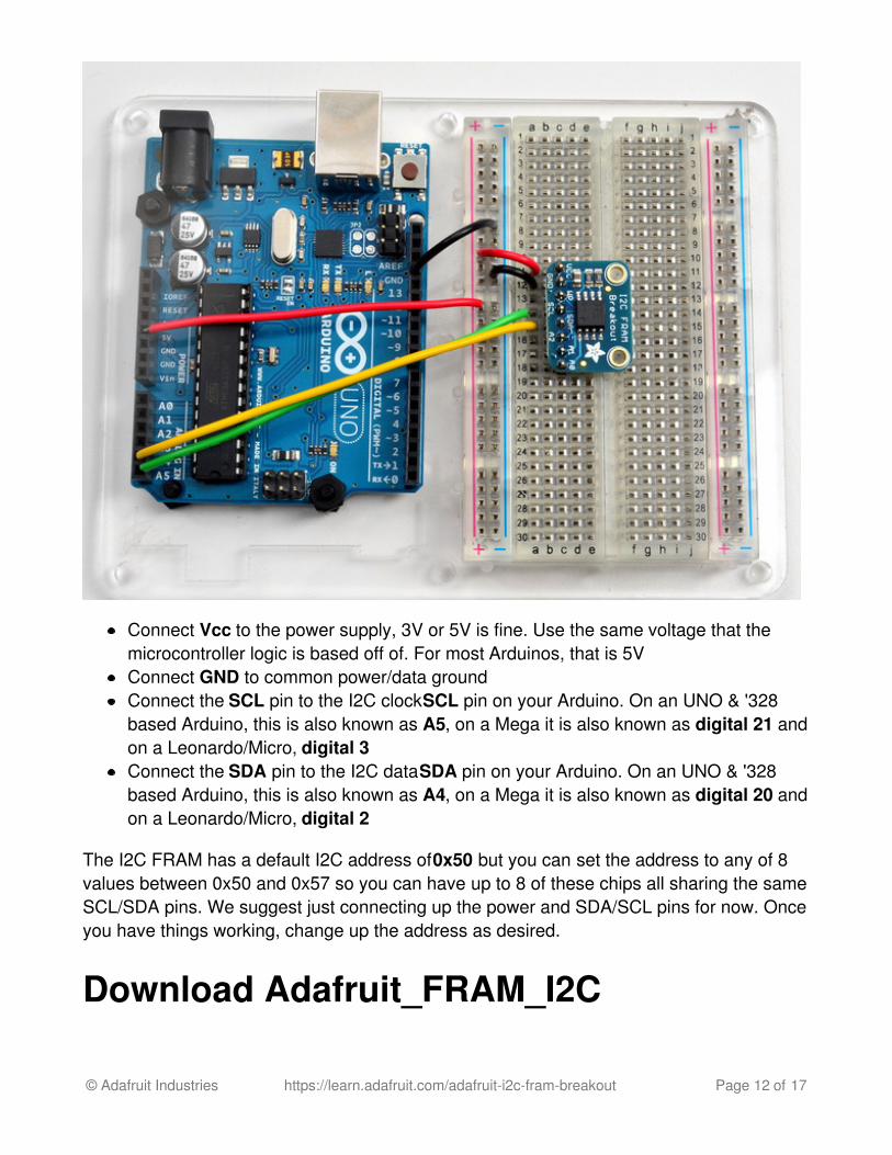
Connect Vcc to the power supply, 3V or 5V is fine. Use the same voltage that themicrocontroller logic is based off of. For most Arduinos, that is 5VConnect GND to common power/data groundConnect the SCL pin to the I2C clock SCL pin on your Arduino. On an UNO & '328based Arduino, this is also known as A5, on a Mega it is also known as digital 21 andon a Leonardo/Micro, digital 3Connect the SDA pin to the I2C data SDA pin on your Arduino. On an UNO & '328based Arduino, this is also known as A4, on a Mega it is also known as digital 20 andon a Leonardo/Micro, digital 2
The I2C FRAM has a default I2C address of 0x50 but you can set the address to any of 8values between 0x50 and 0x57 so you can have up to 8 of these chips all sharing the sameSCL/SDA pins. We suggest just connecting up the power and SDA/SCL pins for now. Onceyou have things working, change up the address as desired.
Download Adafruit_FRAM_I2C
© Adafruit Industries https://learn.adafruit.com/adafruit-i2c-fram-breakout Page 12 of 17
To begin reading and writing data to the chip, you will need to downloadAdafruit_FRAM_I2C from our github repository (http://adafru.it/dtq). You can do that byvisiting the github repo and manually downloading or, easier, just click this button todownload the zipDownload Adafruit FRAM i2c Libraryhttp://adafru.it/dtrRename the uncompressed folder Adafruit_FRAM_I2C and check that theAdafruit_FRAM_I2C folder contains Adafruit_FRAM_I2C.cpp and Adafruit_FRAM_I2C.h
Place the Adafruit_FRAM_I2C library folder your arduinosketchfolder/libraries/ folder. You may need to create the libraries subfolder if its your first library. Restart the IDE.
We also have a great tutorial on Arduino library installation at:http://learn.adafruit.com/adafruit-all-about-arduino-libraries-install-use (http://adafru.it/aYM)
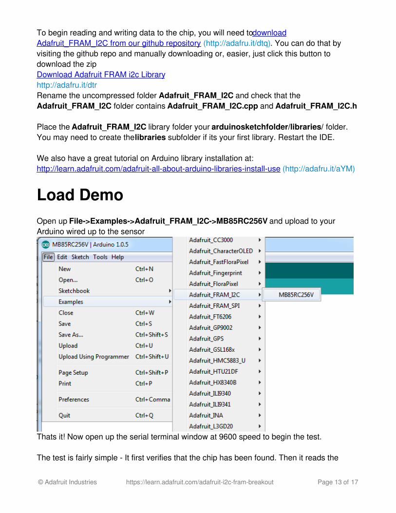
Load DemoOpen up File->Examples->Adafruit_FRAM_I2C->MB85RC256V and upload to yourArduino wired up to the sensor
Thats it! Now open up the serial terminal window at 9600 speed to begin the test.
The test is fairly simple - It first verifies that the chip has been found. Then it reads the
© Adafruit Industries https://learn.adafruit.com/adafruit-i2c-fram-breakout Page 13 of 17
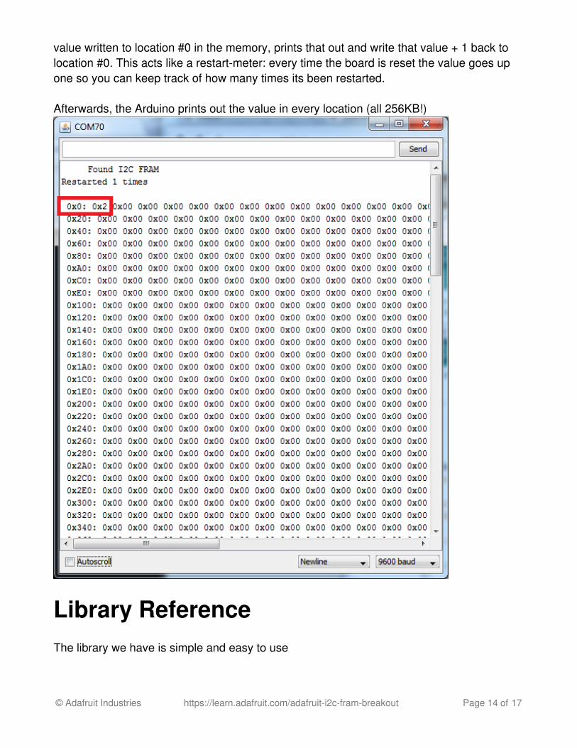
value written to location #0 in the memory, prints that out and write that value + 1 back tolocation #0. This acts like a restart-meter: every time the board is reset the value goes upone so you can keep track of how many times its been restarted.
Afterwards, the Arduino prints out the value in every location (all 256KB!)
Library ReferenceThe library we have is simple and easy to use
© Adafruit Industries https://learn.adafruit.com/adafruit-i2c-fram-breakout Page 14 of 17
You can create the FRAM object with
Adafruit_FRAM_I2C fram = Adafruit_FRAM_I2C();
Then when you begin(), pass in the i2c address. The default is 0x50 so if you don't put anyvalue in the default is used.If you have different addresses, call something like
fram.begin(0x53)
for example.
Then to write a value, call
fram.write8(address, byte-value);
to write an 8-bit value to the address locationLater on of course you can also read with
fram.read8(address);
which returns a byte reading.
© Adafruit Industries https://learn.adafruit.com/adafruit-i2c-fram-breakout Page 15 of 17
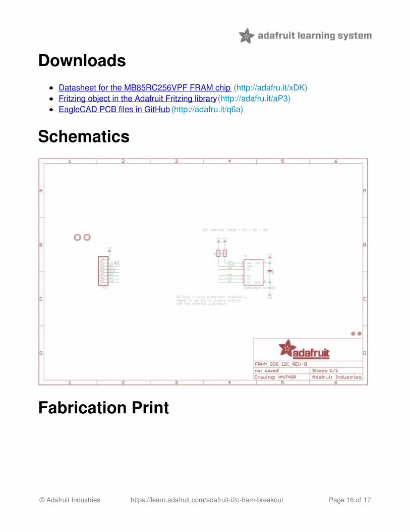
DownloadsDatasheet for the MB85RC256VPF FRAM chip (http://adafru.it/xDK)Fritzing object in the Adafruit Fritzing library (http://adafru.it/aP3)EagleCAD PCB files in GitHub (http://adafru.it/q6a)
Schematics
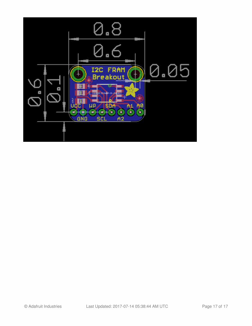
Fabrication Print
© Adafruit Industries https://learn.adafruit.com/adafruit-i2c-fram-breakout Page 16 of 17
© Adafruit Industries Last Updated: 2017-07-14 05:38:44 AM UTC Page 17 of 17


![FERROELECTRIC RAM [FRAM] - Study Mafiastudymafia.org/wp...FERROELECTRIC-RAM-FRAM-Report.pdf · A Seminar report On FERROELECTRIC RAM [FRAM] Submitted in partial fulfillment of the](https://img.pdfslide.us/doc/110x75/5b94f2f009d3f2130d8dd6e1/ferroelectric-ram-fram-study-a-seminar-report-on-ferroelectric-ram-fram.jpg)


![FERROELECTRIC RAM [FRAM]](https://img.pdfslide.us/doc/110x75/56816799550346895ddcd567/ferroelectric-ram-fram.jpg)