Embed Size (px)
Citation preview
Adafruit FT232H BreakoutCreated by Tony DiCola
Last updated on 2020-02-14 04:48:45 PM UTC

Overview
Wouldn't it be cool to drive a tiny OLED display (https://adafru.it/eau), read a color sensor (http://adafru.it/1334), or evenjust flash some LEDs directly from your computer? Sure you can program an Arduino (http://adafru.it/50) orTrinket (http://adafru.it/2000) to talk to these devices and your computer, but why can't your computer just talk to thosedevices and sensors itself? Well, now your computer can talk to devices using the Adafruit FT232H breakout board!
NEW: As of Feb 12, 2020 we have given this venerable board a makeover! We now have a modern USB C connectoron the board (instead of micro USB), a I2C switch to connect D1 and D2 for easy I2C interfacing, 3V power output pin
© Adafruit Industries https://learn.adafruit.com/adafruit-ft232h-breakout Page 3 of 48

up to 500mA, and a Stemma QT connector (https://adafru.it/HMF) that lets you plug & play any StemmaQT (https://adafru.it/HMF) or Qwiic devices, sensors and displays. This revision is completely back-compatible forboard size, mounting holes and pinouts (the additional 3V/GND pins are where previously there were none and do notchange the pinout, they can be left disconnected).
What can the FT232H chip do? This chip from FTDI (https://adafru.it/c97) is similar to their USB to serial converterchips but adds a 'multi-protocol synchronous serial engine' which allows it to speak many common protocols like SPI,I2C, serial UART, JTAG, and more! There's even a handful of digital GPIO pins that you can read and write to do thingslike flash LEDs, read switches or buttons, and more. The FT232H breakout is like adding a little swiss army knifefor serial protocols to your computer!
© Adafruit Industries https://learn.adafruit.com/adafruit-ft232h-breakout Page 4 of 48

Interested in learning more about the FT232H and its capabilities? Continue on to read about how to assemble,configure, and access the capabilities of the FT232H breakout. Also be sure to skim and read the FT232Hdatasheet (https://adafru.it/eav) for more information about the chip.
© Adafruit Industries https://learn.adafruit.com/adafruit-ft232h-breakout Page 5 of 48

Assembly &Wiring
Assembly
To assemble the FT232H breakout you'll need to solder the included headers to the breakout board. If you haven'tsoldered before, make sure to first read the guide to excellent soldering (https://adafru.it/dgp) and try practicing withsome scrap wires and components.
© Adafruit Industries https://learn.adafruit.com/adafruit-ft232h-breakout Page 6 of 48

Start by trimming the male headers to the length of the pin holes on the breakout board. You should have two rows ofmale headers with 10 pins each.
Then insert the longer pins of the headers into a breadboard so that the pin holes on the FT232H breakout slideperfectly through the header pins sticking out the top of the breadboard.
Using a soldering iron and some solder, carefully solder all the pins to the FT232H breakout board.
If you aren't clear on the steps above, check out an assembly guide for other breakout boards like the VS1053 audioboard (https://adafru.it/jFo). You should follow the same steps to solder the header pins to the FT232H breakoutboard.
Once the headers are soldered to the board, plug in a micro USB cable to the port on the FT232H breakout and thenplug the cable into a computer or laptop. You should see a green LED next to the 5V pin on the breakout light up. Congratulations your FT232H board is assembled!
Wiring
Below is a quick description of the pins on the FT232H breakout. You'll learn about these pins in more detail in theSerial UART (https://adafru.it/jFp) and MPSSE Setup (https://adafru.it/jFq) sections of the guide.
5V - This is a 5 volt power source connected directly to the USB bus. Don't pull more than about 400-500mA ofcurrent from this pin or else you might damage your computer's USB port!GND - This is the ground of the FT232H breakout.D0 through D7 - These are the ADBUS pins on the FT232H chip and are used for the serial UART and otherserial protocols. You can also use some of them as GPIO pins for digital inputs and outputs.C0 through C9 - These are the ACBUS pins on the FT232H chip and are mainly used as GPIO pins for digitalinputs and outputs. Note that pins C8 and C9 are not controlled by software and can only be assignedfunctionality by changing the EEPROM of the chip. You'll learn more about these two pins in the more infosection.
© Adafruit Industries https://learn.adafruit.com/adafruit-ft232h-breakout Page 7 of 48

Serial UART
Out of the box the FT232H is configured to act just like an FTDI friend USB to serial UARTconverter (https://adafru.it/dQa). This is great for talking to a serial device like an Arduino from your computer. It's safeto use with both 3.3 volt and 5 volt signals. This means the FT232H breakout can used to safely talk to an Arduino's 5volt serial ports, and a Raspberry Pi or BeagleBone Black's 3.3 volt serial ports!
When used as a serial UART the FT232H breakout pins have the following serial functions:
D0 - TX or transmit pin. This pin is the serial data output by the FT232H chip and should be connected to the RXor receive pin of a serial device.D1 - RX or receive pin. This pin is the serial data input for the FT232H chip and should be connected to the TX ortransmist pin of a serial device.D2 - RTS or ready to send pin. This is an optional pin for flow control of serial connections.D3 - CTS or clear to send pin. Like RTS, this is an optional pin for flow control.D4 - DTR or data terminal ready pin. Another optional pin for flow control in RS-232 serial connections.D5 - DSR or data set ready pin. Like DTR, this is another optional pin for flow control in RS-232 serialconnections.D6 - DCD or data carrier detect pin. This is an optional pin that is sometimes used in RS-232 serialcommunication.
The most important and commonly used serial pins are D0 and D1 for the TX and RX pins. The other pins are onlynecessary if you're using a device with flow control or specific RS-232 serial needs.
USB Serial Drivers
Before you can use the FT232H as a serial UART you need to make sure the proper serial port drivers are installed. Luckily most operating systems include FTDI's serial UART driver so there typically isn't any installation necessary.
Specifically Mac OSX Mavericks or greater have the FTDI serial driver included automatically. Linux kernel versionssince ~2.6 also have the FTDI serial driver included, so modern Linux distributions like Ubuntu 12.04 or 14.04 shouldwork without any driver installation. Windows can usually search online to find the driver automatically, however if thatfails see below for manual driver installation instructions.
If for some reason your operating system doesn't have FTDI serial drivers installed, you can download and install officialdrivers from FTDI's site (https://adafru.it/aJv). There are drivers available for Windows 7 & 8, Mac OSX, and Linux.
Windows Serial Driver Installation
Below I'll briefly walk through installation of the FTDI serial driver for Windows since it is a common platform to installthe driver.
First start with your Windows 7, 8, or 8.1 machine booted and the FT232H board disconnected from the PC.
Download the FTDI serial driver (sometimes called VCP or virtual COM port) here (https://adafru.it/aJv), make sure topick the Windows setup executable version of the driver.
Next open explorer and navigate to the folder where the driver executable was downloaded. Right click on the fileand select Run as administrator as shown below to start the installation. It's important to run as administartor or elsethe driver installation will fail to copy files to Window's system directories.
© Adafruit Industries https://learn.adafruit.com/adafruit-ft232h-breakout Page 8 of 48

Now click through the setup pages, read and accept the license agreement, etc. to install the driver. The aren't anyconfiguration or setup options you need to change or worry about in the installation.
Once the installation is done you might need to reboot your machine if the installation program tells you to do so.
After rebooting, plug in the FT232H breakot to your PC using a USB micro cable. You should see a message pop upthat the device is recognized and a driver is being installed.
To check that the serial port installed successfully and find the COM port assigned to it, open device manager byclicking the start menu and searching for Device Manager.
Inside device manager look under the Ports (COM & LPT) node and you should see a USB Serial Port (COMx) device,where x is a number like 5. This COMx is the COM port assigned to the FT232H serial UART, and what you should usewhen connecting to the serial port in the Arduino IDE or with a serial terminal program.
However if for some reason you don't see the USB Serial Port (COMx) device or Ports (COM & LPT) node, you mightneed to enable the VCP mode for the FTDI device. To do this open the Universal Serial Bus controllers node at thebottom of Device Manager and you should see a USB Serial Converter node. Right click this node and click theProperties menu, then click the Advanced tab at the top. Make sure the Load VCP checkbox is checked and then clickOK. See the picture below for the configuration page and device manager view you should see.
© Adafruit Industries https://learn.adafruit.com/adafruit-ft232h-breakout Page 9 of 48

Now unplug and plug in again the FT232H board and check device manager again to find the USB Serial Port (COMx)node in the Ports (COM & LPT) node. That's it, you're all set to access the device as a serial COM port in Windows!
Serial Usage
Once any necessary serial port drivers are installed, you're ready to use the FT232H as a USB to serial UART. Let'sperform a simple loopback test to confirm you can read and write data with the UART. This test will connect the TX pinto the RX pin so any data sent to serial UART will be immediately received and echoed back to you.
Using a jumper wire, connect pin D0 (TX) to D1 (RX) on the FT232H breakout as shown below.
Now open a serial console for the FT232H board and check that anything you type is echoed back to you.
© Adafruit Industries https://learn.adafruit.com/adafruit-ft232h-breakout Page 10 of 48

Windows
On Windows you can use PuTTY (https://adafru.it/aWh) as a serial console. Download and run PuTTY, then configure itfor a Connection type of Serial as shown below on the right. The Serial line should be set to the COM port you foundfor the USB serial converter in device manager (shown on the left), in this case COM5. Speed should be set to 9600baud.
Click open and you should see an empty terminal screen appear. Try typing a message and you should see what youtype echoed back to you, like below:
If you don't see anything, make sure you've connected the D0 pin to the D1 pin on the FT232H board.
Also make sure you're using the right COM port for the FT232H device. Try unplugging any other USB to serialconverter (including development boards like Arduinos!) and only connecting the FT232H board to make sure you canfind its COM port in device manager.
© Adafruit Industries https://learn.adafruit.com/adafruit-ft232h-breakout Page 11 of 48

Mac OSX
On a Mac you can use a few included terminal commands to list serial ports and connect to a serial port to test theloopback connection.
First start with the FT232H board disconnected and open a terminal to run the following command to list all serialports.
ls /dev/tty.*
You should see a list of devices, such as:
/dev/tty.Bluetooth-Incoming-Port /dev/tty.usbmodem20 /dev/tty.Bluetooth-Modem /dev/tty.usbmodem22 /dev/tty.usbmodem1d111 /dev/tty.usbmodem24
Now connect the FT232H breakout to the computer, wait a moment, and run the same ls command again. You shouldsee a new device in the list, such as:
/dev/tty.Bluetooth-Incoming-Port /dev/tty.usbmodem20/dev/tty.Bluetooth-Modem /dev/tty.usbmodem22/dev/tty.usbmodem1d111 /dev/tty.usbmodem24/dev/tty.usbserial-0000111D
The new device, /dev/tty.usbserial-0000111D, is the FT232H serial UART. You can use this device with a program likescreen to open a serial connection. Run the following command in the terminal to open the serial UART:
screen /dev/tty.usbserial-0000111D 9600
Replace the /dev/tty.usbserial name with the name of the device you found after running the ls commands above. The9600 after the name is the baud rate to open the screen connection.
Once screen opens the connection you should see a blank screen. Try typing characters and you should see themechoed back in the terminal. Congratulations, your serial loopback test is a success!
You can exit screen by pressing Ctrl-a and then Ctrl-\.
Linux
On Linux distributions such as Ubuntu 12.04 or 14.04 you can run terminal commands that are very similar to thoseshown above for Mac OSX. The only difference is that you should run the following ls command to list serial devices:
ls /dev/tty*
Run the above command before and after plugging in the FT232H breakout to find the path to the new device thatwas added. On a distribution like Ubuntu you will typically see a path like /dev/ttyUSB0.
To open the serial port use the exact same screen command as mentioned above for Mac OSX. Replace the path
© Adafruit Industries https://learn.adafruit.com/adafruit-ft232h-breakout Page 12 of 48

parameter with the path to the FT232H device you found above.
Note you might need to press Ctrl-a and then \ to quit screen on Ubuntu or other Linux distributions.
Other Serial UART Uses
You can use the serial UART on the FT232H just like you would any FTDI friend or similar USB to serial UART. Remember the FT232H breakout can work with 3.3 volt and 5 volt boards (that accept a 3.3 volt input as most do) soit's perfect for connecting to small embedded Linux boards like the Raspberry Pi.
For example to connect to a Raspberry Pi just connect the FT232H ground to Raspberry Pi ground, D0 (TX) toRaspberry Pi RX, and D1 (RX) to Raspberry Pi TX like below:
Use PuTTY or screen to open the FT232H serial port at 115200 baud and you'll be accessing the Raspberry Pi's serialport!
You can find more details on accessing a Raspberry Pi through its serial console in this console cableguide (https://adafru.it/jFr). The FT232H breakout can be used instead of the console cable mentioned in the guide!
© Adafruit Industries https://learn.adafruit.com/adafruit-ft232h-breakout Page 13 of 48

Python Setup &Usage
Python Setup & Usage (https://adafru.it/FWD)
© Adafruit Industries https://learn.adafruit.com/adafruit-ft232h-breakout Page 14 of 48

MPSSE Setup (Deprecated)
The Multi-Protocol Synchronous Serial Engine, or MPSSE, is the heart of the FT232H chip which allows it to speakmany different protocols such as I2C, SPI, and more. When the chip is in MPSSE mode it changes the D0 to D3 pins tohave special serial protocol functions:
D0 - Clock signal output. This line can be configured as a clock that runs at speeds between ~450Hz to 30Mhz.D1 - Serial data output. This is for outputting a serial signal, like the MOSI line in a SPI connection.D2 - Serial data input. This is for reading a serial signal, like the MISO line in a SPI connection.D3 - Serial select signal. This is a chip select or chip enable signal to tell a connected device that the FT232H isready to talk to it.
In addition to the serial protocol pins above, the MPSSE mode allows you to control other pins as general purposedigital inputs or outputs. These are great for controlling chip select, reset, or other lines on chips. You can even usethe GPIO to read switches, blink LEDs, and more!
The pins which are controllable as GPIO in MPSSE mode are D4 to D7 and C0 to C7, for a total of 12 GPIO pins. Thesepins can be configured individually as digital inputs or outputs.
Note that pins C8 and C9 are not controllable as GPIO pins. These two pins have a special function that can be set inthe EEPROM of the chip--you'll learn more about these later.
To use the MPSSE mode of the chip you'll need to use some special software and programming libraries. There areactually a few options for software that can talk to the FT232H and its MPSSE component:
FTDI's official D2XX drivers and libraries (https://adafru.it/eaB).
These drivers and libraries are produced by FTDI and provide low level access to FTDI chip functions. There are binary versions of the library available for Windows, Mac OSX, and Linux. This is a good optionto consider if you run into limitations or issues with other drivers. There's a good programmingguide (https://adafru.it/eaC) and example code (https://adafru.it/eaD) available too.
FTDI's LibMPSSE-I2C (https://adafru.it/eaE) and LibMPSSE-SPI (https://adafru.it/eaF) libraries.
These libraries build on top of the D2XX driver above and provide a simpler interface to I2C and SPIcommunication with the FT232H's MPSSE component.
libFTDI library (https://adafru.it/df4)
This is an open source library that's similar to the D2XX library and provides a low level interface to FTDIchip functions. There's even a Python interface which makes this library a little easier to use compared tothe D2XX library.
libmpsse library (https://adafru.it/df5)
Like the libMPSSE-I2C and libMPSSE-SPI libraries, this library builds on the libFTDI library and provides asimpler interface for I2C and SPI protocols using the MPSSE component. One thing to note is that hislibrary is currently only supported on Mac OSX and Linux.
This MPSSE page has been deprecated in favor of the much simpler Blinka support library which is documented here https://learn.adafruit.com/circuitpython-on-any-computer-with-ft232hThis page is for historical/research purposes only, Python 2 is completely deprecated and we do not support the old Python GPIO library anymore!
�
© Adafruit Industries https://learn.adafruit.com/adafruit-ft232h-breakout Page 15 of 48

Adafruit Python GPIO library (https://adafru.it/eaG)
To make using the FT232H simpler, Adafruit's Python GPIO library has been updated to include a simpleinterface for accessing GPIO, SPI, and I2C on the FT232H with the Python programming language. Usingthis library you can control the GPIO pins and send or received SPI & I2C commands much likeprogramming those interfaces on a Raspberry Pi or BeagleBone Black. This library is built on top of thelibFTDI library and supports Windows, Mac OSX, and Linux platforms.
In this guide I'll show you how to setup and use the Adafruit Python GPIO library (https://adafru.it/eaG) to access GPIO,SPI, and I2C devices using the FT232H board's MPSSE component. You can write Python programs to control GPIOpins and send/receive SPI & I2C commands directly from your computer using the FT232H breakout.
One thing to note, when you're using the MPSSE mode of the FT232H the serial UART mode will be disabled. Thismeans you can't use both the serial UART and MPSSE GPIO, SPI, I2C, etc. modes of the chip at the same time.
To learn how to enable MPSSE modes and install the Adafruit Python GPIO library, continue on to the next page that'sappropriate for your platform (Windows, Mac OSX, or Linux).
© Adafruit Industries https://learn.adafruit.com/adafruit-ft232h-breakout Page 16 of 48

Windows (Deprecated)
To access the MPSSE mode of the FT232H on Windows we need to install special drivers and software. We'll use atool called Zadig to replace the FTDI driver for the FT232H with a libusb-based driver required by libftdi. Then we'lldownload a libftdi binary and install it for Python to access. Finally we'll install the Adafruit Python GPIO library. Carefully follow the steps below to setup the software.
Note: When you enable MPSSE mode the serial UART driver will be disabled. If you want to disable MPSSE mode andenable the serial UART again I'll show instructions at the end of the page.
First before you get started make sure you have Python 2.7 installed. You can download the latest Python 2.7 installerhere (https://adafru.it/eaH) (at the time of writing it's version 2.7.8, but any 2.7.x version should work--unfortunately the3.x series isn't supported yet).
Download the MSI installer for your version of Windows, you must install the 32-bit version, and run the installer. Install Python into its standard location, typically C:\python27. Also make sure to install the option to add Python tothe system path so you can easily call the Python interpretor from a command terminal.
libusb Driver Install
Download the appropriate Zadig tool for your version of Windows at its homepage (https://adafru.it/eaI). This toolsimplifies the installation of a libusb driver for the FT232H device.
Before you run the tool unplug all FTDI devices from your computer. This includes devices likebArduinos whichinclude an FTDI chip as a USB to serial converter. You want to unplug these devices to make sure you don'taccidentally select one with the tool and replace its driver.
After all the FTDI devices are unplugged, plug in your FT232H breakout to the computer so it is the only FTDI deviceconnected to the computer.
Now run the Zadig tool executable you just downloaded (there is no installation necessary, the executable is theprogram). Click the Options menu and select the List All Devices item below:
This MPSSE page has been deprecated in favor of the much simpler Blinka support library which is documented here https://learn.adafruit.com/circuitpython-on-any-computer-with-ft232hThis page is for historical/research purposes only, Python 2 is completely deprecated and we do not support the old Python GPIO library anymore!
�
© Adafruit Industries https://learn.adafruit.com/adafruit-ft232h-breakout Page 17 of 48

The list box of devices should populate with many devices. Select the USB Serial Converter device shown below.
Note: Make sure to select the device with Driver equal to FTDIBUS and USB ID equal to 0403 6014! If you pick thewrong device you might accidentally uninstall another device's driver and make it inoperable.
Click the up/down arrows on the driver select box to the right of the green arrow and select the libusbK driver asshown above.
Now click the Replace Driver button to replace the FTDI driver with the libusb-based driver. After the driverreplacement finishes you can close Zadig tool.
To check that the driver was successfully replaced, open Device Manager from Control Panel or searching in the Startmenu. You should see a new top level node libusbK USB Devices and the USB Serial Converter underneath it asshown below.
© Adafruit Industries https://learn.adafruit.com/adafruit-ft232h-breakout Page 18 of 48

If you see the libusbK node and USB serial device, move on to the next step to install libftdi.
If you don't see the libusbK node, try unplugging and plugging back in the FT232H breakout. If you still don't see thenode, run Zadig tool again and follow the steps above again to make sure you replace the FTDI driver for the devicewith the libusbK driver.
libftdi Install
This step will install libftdi's Python library. Carefully follow the steps below to make sure the library is installed.
Start by downloading the binary version of the libftdi library by clicking the button below. This binary is provided by thepicusb USB resources project (https://adafru.it/srb).
https://adafru.it/src
https://adafru.it/src
Unzip the archive and you should see a series of folders like below:
© Adafruit Industries https://learn.adafruit.com/adafruit-ft232h-breakout Page 19 of 48

We need to copy some files from libftdi into Python's package directory. Open another Explorer window and navigateto the location you installed Python earlier, typically C:\python27. Inside the Python directory navigate to the Lib > site-packages folder. Files you copy into this folder will be available globally as packages that your Python scripts can use.
From the libftdi archive folder, copy all the .DLL files from the bin folder into the Python site-packages folder,specifically:
bin\libftdi1.dllbin\libftdipp1.dllbin\libgcc_s_dw2-1.dllbin\libiconv-2.dllbin\libintl-8.dllbin\libstdc++-6.dllbin\libusb-1.0.dll
Then also copy in the files from the python2.7 folder of the libftdi archive into the Python site-packages folder:
python2.7\_ftdi.pydpython2.7\ftdi1.py
To double check you copied in the right files, your Python site-packages folder should have at least the files belowinside it (you might see other files & directories, but don't worry they can be ignored):
© Adafruit Industries https://learn.adafruit.com/adafruit-ft232h-breakout Page 20 of 48

That's all you need to do to install libftdi. Let's move on to install the Adafruit Python GPIO library next.
Adafruit Python GPIO Library Install
Finally let's install the Adafruit Python GPIO library which will allow your Python scripts to access the MPSSEfunctionality of the FT232H breakout
First download an archive of the library by clicking the button below:
https://adafru.it/eaL
https://adafru.it/eaL
Unzip the contents and then open a command terminal and navigate to the directory where the library was unzipped. Execute the following command to install the library:
python setup.py install
Note if you see an error that Python can't be found then make sure you installed Python 2.7 as mentioned at the top ofthe page, and that it was added to your system path. Here's more details on how to manually add Python to yoursystem path (https://adafru.it/eaM).
You should see the Python library install itself with text similar to the below:
© Adafruit Industries https://learn.adafruit.com/adafruit-ft232h-breakout Page 21 of 48

Now let's test if both the libftdi and Adafruit Python GPIO libraries were correctly installed. In the commandterminal run Python by executing:
python
Once the Python interpretor has loaded, type the following at the >>> prompt:
import Adafruit_GPIOimport ftdi1
You should see no response from the Python interpretor after entering each command like below:
No response from the Python interpretor is a good sign because it means Python was able to successfully load thelibraries.
If you see an error message or failure after entering a command, unfortunately something went wrong with theinstallation of the library. Go back through the steps above and carefully check that nothing was missed. You want tomake sure all the libftdi files are copied into the Python site-packages folder, and that the Adafruit Python GPIO library
© Adafruit Industries https://learn.adafruit.com/adafruit-ft232h-breakout Page 22 of 48

installed itself successfully.
Once you've confirmed Python can load the libraries, exit the Python interpretor by typing:
quit()
Congratulations, the MPSSE mode drivers and Python libraries are installed and ready to use! Move on to the nextsection to see how to use the MPSSE mode to access GPIO, SPI, I2C, etc.
libusb Driver Uninstall
Should you ever want to disable the MPSSE mode for the FT232H and return to its serial UART mode follow the stepsbelow.
First make sure the FT232H breakout is plugged in to the computer. Then open Device Manager and find the libusbKUSB Devices node and the USB Serial Converter child of that node. Right click the device and select Uninstall asshown below:
In the dialog that appears make sure the 'Delete the driver software for this device.' option is checked as shown below:
© Adafruit Industries https://learn.adafruit.com/adafruit-ft232h-breakout Page 23 of 48

Click OK and the libusb driver should be completely uninstalled for the device.
Now unplug the FT232H breakout board and go back to the Serial UART page (https://adafru.it/jFp) to find theinstructions for installing the Windows serial driver. Follow those instructions again and you should be set with thedevice acting as a USB serial UART again.
© Adafruit Industries https://learn.adafruit.com/adafruit-ft232h-breakout Page 24 of 48

Mac OSX (Deprecated)
To access the MPSSE mode on Mac OSX we need to install libftdi and the Adafruit Python GPIO library. Carefullyfollow the steps below to install these libraries.
Note that these steps were tested using OSX Mavericks. The steps should work for later versions like Yosemite, butyou might need to search for extra help on installing Xcode command line tools below.
First before you get started you will need to make sure you have Xcode (https://adafru.it/eaN) and the Xcodecommand line tools installed. This is required to compile and build libraries from source. Follow the steps in theanswer to this Stackoverflow question (https://adafru.it/df2) for a good walkthrough of how to install the Xcodecommand line tools.
Next install the Homebrew package manager (https://adafru.it/df3) which will be used to install the necessary libftdidepedencies. Follow the installation instructions from the bottom of Homebrew's homepage (https://adafru.it/df3) toinstall it.
Now run the following commands in a terminal in order to install libftdi and its dependencies:
brew install cmakebrew install libusbbrew install swigbrew install --build-from-source https://raw.githubusercontent.com/Homebrew/homebrew-core/99ebd41decde2dd0fbab799bed88cfcb230a096a/Formula/libftdi.rbmkdir -p ~/Library/Python/2.7/lib/python/site-packagesecho '/usr/local/lib/python2.7/site-packages' > ~/Library/Python/2.7/lib/python/site-packages/homebrew.pth
The commands above should complete without any errors. If you do see errors, make sure you have Xcode andHomebrew successfully installed and try again.
Next download the Adafruit Python GPIO library by clicking the button below:
https://adafru.it/eaL
https://adafru.it/eaL
Unzip the archive and navigate to the folder inside a terminal. Then run the following command to install the library:
sudo python setup.py install
You should see the Python library successfully install without any errors.
To test the libraries are installed run the following command in a terminal to open the Python interpretor:
This MPSSE page has been deprecated in favor of the much simpler Blinka support library which is documented here https://learn.adafruit.com/circuitpython-on-any-computer-with-ft232hThis page is for historical/research purposes only, Python 2 is completely deprecated and we do not support the old Python GPIO library anymore!
�
© Adafruit Industries https://learn.adafruit.com/adafruit-ft232h-breakout Page 25 of 48

python
At the Python interpretor >>> prompt type the following commands to test loading the libraries:
import Adafruit_GPIOimport ftdi1
You should see no response from the Python interpretor after entering each line. If you do see an error that a modulecannot be loaded, go back to the libftdi installation steps above and carefully check they completed successfully.
If there are no errors, congratulations you've successfully installed libftdi and the Adafruit Python GPIO library! Moveon to the next section to learn how to access the MPSSE mode GPIO, SPI, I2C, etc.
To quit the Python interpretor enter the following:
quit()
Disable FTDI Driver on OSX 10.11 El Capitan
Note on OSX 10.11 El Capitan and higher you might need to permanently disable Apple's built in FTDI serial driver inorder to use all of the FT232H's functions. This can be accomplished by following section 7.3 Block with D2xxHelperfrom the FTDI app note here (https://adafru.it/ucE).
© Adafruit Industries https://learn.adafruit.com/adafruit-ft232h-breakout Page 26 of 48

Linux (Deprecated)
To access the MPSSE mode on Linux we need to install libftdi and the Adafruit Python GPIO library. Carefully followthe steps below to install these libraries.
Note that these steps are made for Ubuntu 12.04/14.04 and should work with any Debian-based distribution. If you'reusing a different distribution you might need to check its package manager for the appropriate commands to install thementioned dependencies.
In a command terminal execute the following commands to install libftdi and its dependencies.
NOTE: This assumes you're installing on a Debian/Ubuntu/Raspbian-based system and will use Python 2.7. If you'reusing a different version of Python or your distribution installs Python in a different location you might need to changethe paths of the -DPYTHON_xxxx environment variables in the cmake command.
sudo apt-get updatesudo apt-get install build-essential libusb-1.0-0-dev swig cmake python-dev libconfuse-dev libboost-all-devwget http://www.intra2net.com/en/developer/libftdi/download/libftdi1-1.2.tar.bz2tar xvf libftdi1-1.2.tar.bz2cd libftdi1-1.2mkdir buildcd buildcmake -DCMAKE_INSTALL_PREFIX="/usr/" -DPYTHON_INCLUDE_DIR="/usr/include/python2.7" -DPYTHON_LIBRARIES="/usr/lib/python2.7/" ../makesudo make install
The commands above should complete without any errors. If you do see errors, make sure all the dependencies wereinstalled with the apt-get install command.
Next download the Adafruit Python GPIO library by clicking the button below:
https://adafru.it/eaL
https://adafru.it/eaL
Unzip the archive and navigate to the folder inside a terminal. Then run the following command to install the library:
sudo python setup.py install
You should see the Python library successfully install without any errors.
To test the libraries are installed run the following command in a terminal to open the Python interpretor:
This MPSSE page has been deprecated in favor of the much simpler Blinka support library which is documented here https://learn.adafruit.com/circuitpython-on-any-computer-with-ft232hThis page is for historical/research purposes only, Python 2 is completely deprecated and we do not support the old Python GPIO library anymore!
�
© Adafruit Industries https://learn.adafruit.com/adafruit-ft232h-breakout Page 27 of 48

python
At the Python interpretor >>> prompt type the following commands to test loading the libraries:
import Adafruit_GPIOimport ftdi1
You should see no response from the Python interpretor after entering each line. If you do see an error that a modulecannot be loaded, go back to the libftdi installation steps above and carefully check they completed successfully.
If there are no errors, congratulations you've successfully installed libftdi and the Adafruit Python GPIO library! Moveon to the next section to learn how to access the MPSSE mode GPIO, SPI, I2C, etc.
To quit the Python interpretor enter the following:
quit()
© Adafruit Industries https://learn.adafruit.com/adafruit-ft232h-breakout Page 28 of 48

MPSSE Usage (Deprecated)
The next sections will walk through examples of using the Adafruit Python GPIO library to use MPSSE functions likeGPIO, SPI, and I2C.
Make sure you've first installed the libftdi library & Adafruit Python GPIO library by following the steps for your platformin the previous section!
This MPSSE page has been deprecated in favor of the much simpler Blinka support library which is documented here https://learn.adafruit.com/circuitpython-on-any-computer-with-ft232hThis page is for historical/research purposes only, Python 2 is completely deprecated and we do not support the old Python GPIO library anymore!
�
© Adafruit Industries https://learn.adafruit.com/adafruit-ft232h-breakout Page 29 of 48

GPIO (Deprecated)
Using the GPIO pins on the FT232H board is easy with the Python GPIO library that was installed. To demonstrate theusage I'll show a simple example of blinking an LED and reading a digital input.
To get started you'll need the following parts:
Assembled FT232H breakout board.One LED of any color.A small resistor between ~330-1000 Ohms to limit current through the LED.Jumper wires & breadboard.
Connect the parts as follows:
FT232H C0 to the LED anode (longer leg)LED cathode (shorter leg) to one leg of the resistor.Other resistor leg to FT232H GND.FT232H D7 to FT232H GND. This jumper wire will switch between reading a low value or high value on the D7input by moving it between FT232H GND and 5V.
You can see a photo of this setup below:
With this configuration pin C0 will be a digital output that controls if the LED is on or off, depending on the level of theC0 output. Pin D7 will be a digital input that reads if it's at a high level (3-5 volts) or low level (ground).
Now create a file named gpio_test.py in a text editor and fill it with the following Python code:
This MPSSE page has been deprecated in favor of the much simpler Blinka support library which is documented here https://learn.adafruit.com/circuitpython-on-any-computer-with-ft232hThis page is for historical/research purposes only, Python 2 is completely deprecated and we do not support the old Python GPIO library anymore!
�
© Adafruit Industries https://learn.adafruit.com/adafruit-ft232h-breakout Page 30 of 48
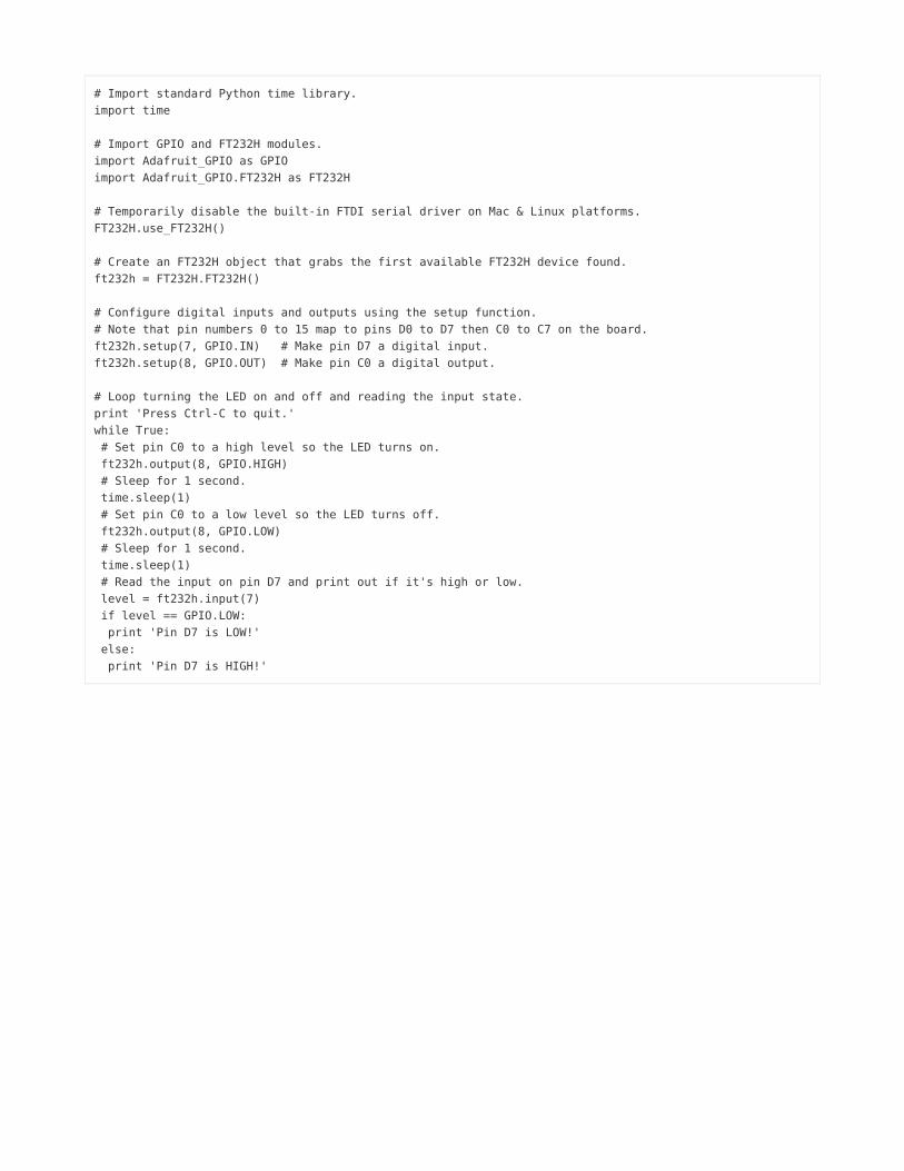
# Import standard Python time library.import time
# Import GPIO and FT232H modules.import Adafruit_GPIO as GPIOimport Adafruit_GPIO.FT232H as FT232H
# Temporarily disable the built-in FTDI serial driver on Mac & Linux platforms.FT232H.use_FT232H()
# Create an FT232H object that grabs the first available FT232H device found.ft232h = FT232H.FT232H()
# Configure digital inputs and outputs using the setup function.# Note that pin numbers 0 to 15 map to pins D0 to D7 then C0 to C7 on the board.ft232h.setup(7, GPIO.IN) # Make pin D7 a digital input.ft232h.setup(8, GPIO.OUT) # Make pin C0 a digital output.
# Loop turning the LED on and off and reading the input state.print 'Press Ctrl-C to quit.'while True: # Set pin C0 to a high level so the LED turns on. ft232h.output(8, GPIO.HIGH) # Sleep for 1 second. time.sleep(1) # Set pin C0 to a low level so the LED turns off. ft232h.output(8, GPIO.LOW) # Sleep for 1 second. time.sleep(1) # Read the input on pin D7 and print out if it's high or low. level = ft232h.input(7) if level == GPIO.LOW: print 'Pin D7 is LOW!' else: print 'Pin D7 is HIGH!'
Save the file and then open a command line terminal and navigate to the folder with gpio_test.py. Run the script byexecuting on Windows:
python gpio_test.py
Or on Mac OSX or Linux run the script as root by executing:
sudo python gpio_test.py
You should see the LED start to blink once a second, and the state of the D7 input is also printed. For example if D7 isconnected to ground you'll see:
Press Ctrl-C to quit.Pin D7 is LOW!Pin D7 is LOW!Pin D7 is LOW!
© Adafruit Industries https://learn.adafruit.com/adafruit-ft232h-breakout Page 31 of 48

Try moving the jumper wire for D7 from ground to 5 volts. You should see the input start to read a high value:
Pin D7 is HIGH!Pin D7 is HIGH!Pin D7 is HIGH!
Swap the jumper wire between ground and 5 volts to see the input value change.
Let's look a little more closely at the code to understand how reading and writing digital GPIO works.
# Import standard Python time library.import time
# Import GPIO and FT232H modules.import Adafruit_GPIO as GPIOimport Adafruit_GPIO.FT232H as FT232H
First the required modules are loaded for this script. The time module will be used to delay for a short period of time.
The Adafruit_GPIO and Adafruit_GPIO.FT232H modules will be imported with shorter names using the 'as' keyword. These modules have all the logic for reading and writing GPIO on the FT232H.
# Temporarily disable the built-in FTDI serial driver on Mac & Linux platforms.FT232H.use_FT232H()
Next the use_FT232H() function is called to temporarily disable any FTDI serial drivers. This command is necessary onMac or Linux platforms because the libftdi library will interfere with the built-in FTDI serial drivers.
You don't really need to run this command on Windows because the FTDI serial driver was disabled using the Zadigtool, however it can't hurt to call the function as it will do nothing on Windows.
# Create an FT232H object that grabs the first available FT232H device found.ft232h = FT232H.FT232H()
Now an FT232H object is created and assigned to the ft232h variable. This will detect the first available FT232Hdevice connected to the computer and initialize its MPSSE for use with GPIO.
Make sure the use_FT232H() function was previously called or else this function will fail!
# Configure digital inputs and outputs using the setup function.# Note that pin numbers 0 to 15 map to pins D0 to D7 then C0 to C7 on the board.ft232h.setup(7, GPIO.IN) # Make pin D7 a digital input.ft232h.setup(8, GPIO.OUT) # Make pin C0 a digital output.
Next the setup() function is called on the FT232H object. This function takes two parameters, the first is the pinnumber and the second is either GPIO.IN or GPIO.OUT to set the pin as a digital input or output.
Remember the pin numbers are 0 to 7 for D0 to D7, and 8 to 15 for C0 to C7.
© Adafruit Industries https://learn.adafruit.com/adafruit-ft232h-breakout Page 32 of 48

# Loop turning the LED on and off and reading the input state.print 'Press Ctrl-C to quit.'while True: # Set pin C0 to a high level so the LED turns on. ft232h.output(8, GPIO.HIGH) # Sleep for 1 second. time.sleep(1) # Set pin C0 to a low level so the LED turns off. ft232h.output(8, GPIO.LOW) # Sleep for 1 second. time.sleep(1)
Now an infinite loop is entered and the LED is turned on and off using the output() function on the FT232H object. Thisfunction takes two parameters, the first is the pin number and the second is GPIO.HIGH/True to set the pin to a highlevel (3.3 volts), or GPIO.LOW/False to set the pin to a low level (ground).
# Read the input on pin D7 and print out if it's high or low. level = ft232h.input(7) if level == GPIO.LOW: print 'Pin D7 is LOW!' else: print 'Pin D7 is HIGH!'
Finally the digital input is read using the input() function on the FT232H object. This function takes one parameter, thepin number to read. The function will return GPIO.LOW/False if the input is at a low level (below about 0.8 volts), andGPIO.HIGH/True if the input is at a high level (above about 0.8 volts, up to 5V max).
That's all there is to use GPIO on the FT232H board! You can use these GPIO pins to turn on and off devices or LEDs,or read switches or pins from other chips.
Be aware that the output pins on the FT232H are only designed to source a few milliamps of current (up to about 16mAper pin). If you need to drive devices that take a lot of current, look into using transistors to switch higher amounts ofcurrent.
© Adafruit Industries https://learn.adafruit.com/adafruit-ft232h-breakout Page 33 of 48

SPI (Deprecated)
The FT232H's MPSSE is great for generating signals to communicate using the SPI protocol. (https://adafru.it/cEC) TheMPSSE can take care of generating a clock signal from about 450hz to 30Mhz, and read & write bytes of data at thatfrequency. The Python GPIO library that was installed includes a small wrapper around MPSSE functions to simplify theuse of reading and writing SPI data.
When using SPI with the FT232H the following pins will have a special meaning:
D0 - SCK / Clock signal. This will be the clock that tells devices when to sample and write data.D1 - MOSI / Data Out. This will output data from the FT232H to the connected device.D2 - MISO / Data In. This will read data from the connected device to the FT232H.
One thing to note is that there isn't an explicit chip select / enable pin. You should use any of the free GPIO pins as adedicated chip select pin and specify that pin when creating the SPI object.
To use SPI with the Python library you need to create an instance of the Adafruit_GPIO.FT232H.SPI class. For examplesee the following code:
import Adafruit_GPIO.FT232H as FT232H
# Temporarily disable FTDI serial drivers.FT232H.use_FT232H()
# Find the first FT232H device.ft232h = FT232H.FT232H()
# Create a SPI interface from the FT232H using pin 8 (C0) as chip select.# Use a clock speed of 3mhz, SPI mode 0, and most significant bit first.spi = FT232H.SPI(ft232h, cs=8, max_speed_hz=3000000, mode=0, bitorder=FT232H.MSBFIRST)
# Write three bytes (0x01, 0x02, 0x03) out using the SPI protocol.spi.write([0x01, 0x02, 0x03])
Notice that the code starts by importing the FT232H part of the GPIO library and disabling the FTDI serial drivers asyour saw in the GPIO example.
Next the code creates a FT232H object also like was done in the GPIO example.
The next line of code creates a FT232H.SPI object using the FT232H device that was just created. An optional chipselect/slave select line is specified using GPIO 8 / pin C0 with the cs parameter value.
Notice too the speed, mode, and bit order of the SPI protocol are specified as parameters of the initializer. Mode 0and bit order of MSBFIRST are actually the default values and do not necessarily need to be specified here, but it'shelpful to show them for clarity.
This MPSSE page has been deprecated in favor of the much simpler Blinka support library which is documented here https://learn.adafruit.com/circuitpython-on-any-computer-with-ft232hThis page is for historical/research purposes only, Python 2 is completely deprecated and we do not support the old Python GPIO library anymore!
�
© Adafruit Industries https://learn.adafruit.com/adafruit-ft232h-breakout Page 34 of 48

Possible mode values are 0 through 3 and they correspond to SPI mode values for AVRprocessors (https://adafru.it/cEC).
Bitorder can be either MSBFIRST for most significant bits to be clocked out first, or LSBFIRST for the least significantbits to be clocked out first.
Finally the last line shows how to send 3 bytes of data out the D1 (MOSI) line using the write() function. The D0 (SCK)line will generate a clock signal, and the D1 (MOSI) line will clock out bits of data with every clock pulse.
There are also SPI functions you can use to read and transfer (read and write at the same time) data:
# Read 3 bytes of data using the SPI protocol.response = spi.read(3)print 'Received {0}'.format(response)
# Write 3 bytes and simultaneously read 3 bytes using the SPI protocl.response = spi.transfer([0x01, 0x02, 0x03])print 'Received {0}'.format(response)
The read() function will read the specified number of bytes on the D2 (MISO) line (sending clock pulses out D0 (SCK)as necessary).
The transfer() function is like calling write() and read() at the same time. The specified array of bytes will be sent out D1(MOSI) while at the same time data will be read from D2 (MISO).
That's all there is to using the SPI protocol with the FT232H and the Adafruit Python GPIO library!
You might also be interested in this tutorial which shows how to use the FT232H breakout with some Adafruit SPI devices (https://adafru.it/jFt) that have been ported to use Adafruit's Python GPIO library.
Driving NeoPixels With SPI
One interesting use of the SPI protocol is driving the colors of WS2811/WS2812 NeoPixel addressable RGB LEDs. These LEDs don't actually use SPI to communicate, instead they have a very specific self-clockedsignal (https://adafru.it/jFu) for sending pixel color bits. However by using a high speed 6Mhz SPI signal we can'oversample' the NeoPixel control signal and generate a close approximation of it from the D1 (MOSI) line of theFT232H.
Note that this method of driving NeoPixels is limited to lighting about 340 pixels at a time. This limitation comes fromthe maximum amount of data that can be sent to the FT232H at one time over the USB bus, about 64 kilobytes of data. Because we're oversampling the NeoPixel control signal each pixel actually takes 24*8 bytes of SPI data (or one byteof SPI data for every bit of pixel data).
To demonstrate lighting NeoPixels with the FT232H breakout you'll need the following parts:
Assembled FT232H breakout board.NeoPixel strip, strand, matrix, etc.
Remember at most you can only light about 340 pixels.
Strong 5 volt power supply to drive the NeoPixels.
Each pixel can take up to 60mA, so driving more than a handful of pixels can quickly add up to a few ampsor more of current. Do not try to power more than a couple NeoPixels over the FT232H 5V line!
© Adafruit Industries https://learn.adafruit.com/adafruit-ft232h-breakout Page 35 of 48

Level converter chip to convert 3.3 to 5 volts OR a power diode that can handle the full power of all theNeoPixels.
The NeoPixel control signal needs to be at least 0.7*Vcc (power supply voltage) which is just a little too highfor the 3.3 volt output of the FT232H breakout. Just like lighting NeoPixels with the RaspberryPi (https://adafru.it/jFv) you need to either convert the control signal to 5 volts using a chip like the74AHCT125 (http://adafru.it/1787), or drop the NeoPixel power supply down slightly below 5 volts using apower diode (http://adafru.it/755).
Jumper wires and breadboard.
In this example I'm lighting a 16 pixel ring so I'll use a power diode that can handle 1 amp of current. If you're usingmore than 16 NeoPixels you'll want a larger power diode, or a level converter chip.
Connect the hardware as follows:
FT232H GND to power supply ground.FT232H D1 (MOSI) to NeoPixel signal input.Power supply positive voltage to diode anode (side without the stripe).NeoPixel positive voltage to diode cathode (side with the stripe).NeoPixel ground to power supply ground.
A picture of the hardware setup is below (note I've added a large capacitor to the power supply as recommended inthe NeoPixel Uberguide (https://adafru.it/iZe)):
Now create a file neopixels.py and fill it with the following code:
import time
import Adafruit_GPIO as GPIOimport Adafruit_GPIO.FT232H as FT232H
class NeoPixel_FT232H(object): def __init__(self, n): # Create an FT232H object.
© Adafruit Industries https://learn.adafruit.com/adafruit-ft232h-breakout Page 36 of 48
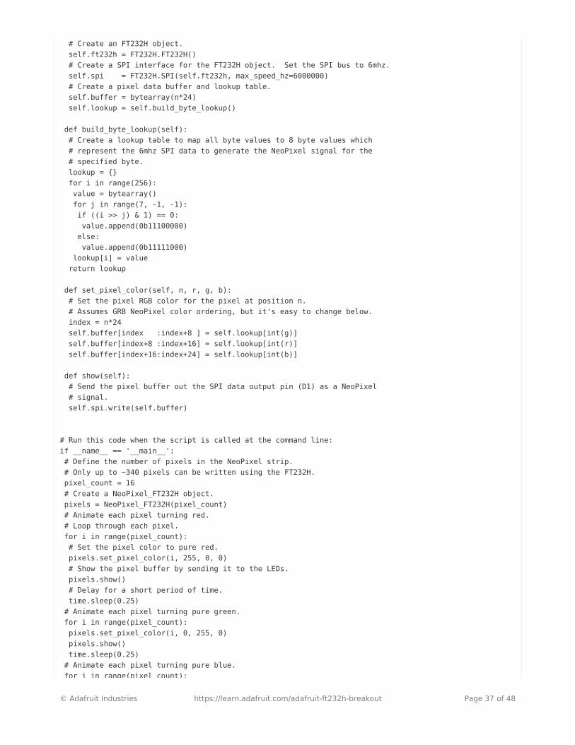
# Create an FT232H object. self.ft232h = FT232H.FT232H() # Create a SPI interface for the FT232H object. Set the SPI bus to 6mhz. self.spi = FT232H.SPI(self.ft232h, max_speed_hz=6000000) # Create a pixel data buffer and lookup table. self.buffer = bytearray(n*24) self.lookup = self.build_byte_lookup()
def build_byte_lookup(self): # Create a lookup table to map all byte values to 8 byte values which # represent the 6mhz SPI data to generate the NeoPixel signal for the # specified byte. lookup = {} for i in range(256): value = bytearray() for j in range(7, -1, -1): if ((i >> j) & 1) == 0: value.append(0b11100000) else: value.append(0b11111000) lookup[i] = value return lookup
def set_pixel_color(self, n, r, g, b): # Set the pixel RGB color for the pixel at position n. # Assumes GRB NeoPixel color ordering, but it's easy to change below. index = n*24 self.buffer[index :index+8 ] = self.lookup[int(g)] self.buffer[index+8 :index+16] = self.lookup[int(r)] self.buffer[index+16:index+24] = self.lookup[int(b)]
def show(self): # Send the pixel buffer out the SPI data output pin (D1) as a NeoPixel # signal. self.spi.write(self.buffer)
# Run this code when the script is called at the command line:if __name__ == '__main__': # Define the number of pixels in the NeoPixel strip. # Only up to ~340 pixels can be written using the FT232H. pixel_count = 16 # Create a NeoPixel_FT232H object. pixels = NeoPixel_FT232H(pixel_count) # Animate each pixel turning red. # Loop through each pixel. for i in range(pixel_count): # Set the pixel color to pure red. pixels.set_pixel_color(i, 255, 0, 0) # Show the pixel buffer by sending it to the LEDs. pixels.show() # Delay for a short period of time. time.sleep(0.25) # Animate each pixel turning pure green. for i in range(pixel_count): pixels.set_pixel_color(i, 0, 255, 0) pixels.show() time.sleep(0.25) # Animate each pixel turning pure blue. for i in range(pixel_count):
© Adafruit Industries https://learn.adafruit.com/adafruit-ft232h-breakout Page 37 of 48
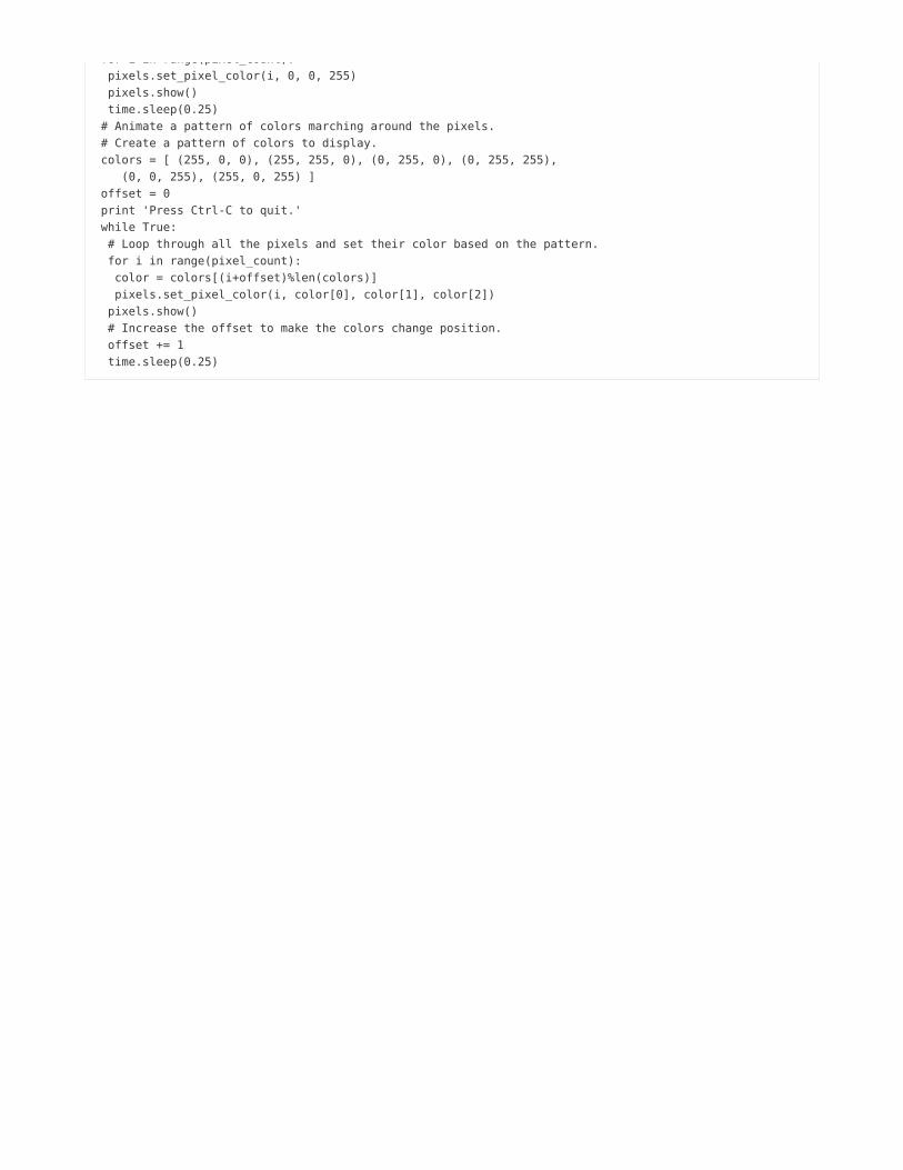
for i in range(pixel_count): pixels.set_pixel_color(i, 0, 0, 255) pixels.show() time.sleep(0.25) # Animate a pattern of colors marching around the pixels. # Create a pattern of colors to display. colors = [ (255, 0, 0), (255, 255, 0), (0, 255, 0), (0, 255, 255), (0, 0, 255), (255, 0, 255) ] offset = 0 print 'Press Ctrl-C to quit.' while True: # Loop through all the pixels and set their color based on the pattern. for i in range(pixel_count): color = colors[(i+offset)%len(colors)] pixels.set_pixel_color(i, color[0], color[1], color[2]) pixels.show() # Increase the offset to make the colors change position. offset += 1 time.sleep(0.25)
Save the file and navigate to the folder with it in a terminal, then execute the following in Windows to run the program:
python neopixels.py
Or on Mac OSX or Linux execute the following to run the program as root:
sudo python neopixels.py
You should see the NeoPixels light up and animate with different colors. Note that you might need to change thepixel_count variable in the main part of the program to match the number of pixels in your NeoPixel strip, circle, matrix,etc.
This code does a couple things at a high level. It first defines a class called NeoPixel_FT232H. This class containssome methods and state which control generating the NeoPixel signal with an FT232H board. The second part of thecode uses the NeoPixel_FT232H class to animate the NeoPixels.
You actually don't need to fully understand the NeoPixel_FT232H class code to use it. This code performs the'oversampling' by using a lookup table to expand each byte of color data into 8 bytes of SPI data that approximates theNeoPixel control signal. The only important thing to know about the NeoPixel_FT232H class is that it exposes aset_pixel_color() function which allows you to set the red, green, and blue color value of a pixel.
Instead let's walk through a bit of the second half of the code that uses the NeoPixel_FT232H class:
# Run this code when the script is called at the command line:if __name__ == '__main__': # Define the number of pixels in the NeoPixel strip. # Only up to ~340 pixels can be written using the FT232H. pixel_count = 16 # Create a NeoPixel_FT232H object. pixels = NeoPixel_FT232H(pixel_count)
This portion of code has an if statement that checks if the program is being run from the command line beforeexecuting. This is just a standard Python idiom for defining the main entry point of a program.
© Adafruit Industries https://learn.adafruit.com/adafruit-ft232h-breakout Page 38 of 48

Inside the if block you can see the number of pixels is defined and set in the pixel_count variable. Then theNeoPixel_FT232H object is created by telling it that number of pixels as its only parameter.
# Animate each pixel turning red. # Loop through each pixel. for i in range(pixel_count): # Set the pixel color to pure red. pixels.set_pixel_color(i, 255, 0, 0) # Show the pixel buffer by sending it to the LEDs. pixels.show() # Delay for a short period of time. time.sleep(0.25) # Animate each pixel turning pure green. for i in range(pixel_count): pixels.set_pixel_color(i, 0, 255, 0) pixels.show() time.sleep(0.25) # Animate each pixel turning pure blue. for i in range(pixel_count): pixels.set_pixel_color(i, 0, 0, 255) pixels.show() time.sleep(0.25)
The next section performs a few simple animations that turn each pixel on with primary colors. You can see a loop isused to go through each pixel and the set_pixel_color() function is called to the pixel color. This function takes 4parameters, the first is the number of the pixel (start at 0), and the last 3 parameters are the red, green, and blue colorcomponents. Each component should be a value from 0 to 255, where 0 is no color and 255 is maximum colorintensity.
After changing the pixel color, the show() function is called to send the colors to the LEDs. You must call show() inorder to make the NeoPixels light up with the colors you've set previously!
Finally notice the time.sleep() function is used to delay for a short period of time (a quarter of a second in this case). This sleep function is very useful for animating color changes that should go somewhat slowly.
# Animate a pattern of colors marching around the pixels. # Create a pattern of colors to display. colors = [ (255, 0, 0), (255, 255, 0), (0, 255, 0), (0, 255, 255), (0, 0, 255), (255, 0, 255) ] offset = 0 print 'Press Ctrl-C to quit.' while True: # Loop through all the pixels and set their color based on the pattern. for i in range(pixel_count): color = colors[(i+offset)%len(colors)] pixels.set_pixel_color(i, color[0], color[1], color[2]) pixels.show() # Increase the offset to make the colors change position. offset += 1 time.sleep(0.25)
Finally the code enters an infinite loop where it animates a rainbow of colors marching across the pixels. This codeuses the same set_pixel_color() function, but has a little extra logic to pick a color from a list and increase the offset ofchosen colors every loop iteration. Also notice the show() function is again called after updating pixel colors in order
© Adafruit Industries https://learn.adafruit.com/adafruit-ft232h-breakout Page 39 of 48

to make the LEDs light up with the desired colors.
That's all there is to controlling NeoPixels with SPI from the FT232H breakout! Feel free to use the code above in yourown NeoPixel projects!
© Adafruit Industries https://learn.adafruit.com/adafruit-ft232h-breakout Page 40 of 48

I2C (Deprecated)
The I2C protocol (https://adafru.it/srd) is another popular protocol for communicating with sensors and devices. I2C ismore complex and sometimes slower than SPI, but only requires two data lines (and a ground) which is desireable insome situations. Luckily the MPSSE component of the FT232H can implement the I2C protocol so you can speak tothese devices with the FT232H breakout.
To use I2C with the Adafruit Python GPIO library and the FT232H board you'll need to setup your circuit in a specialway. In particular you'll need to tie the D1 and D2 pins together with a jumper wire. One of the pins will be read by theF232H as an input, and the other pin will be used as an output. When tied together both these pins form the SDA ordata line for I2C.
The D0 pin alone will be the SCL clock line for I2C.
The second thing you'll need to do with your circuit is add explicit pull-up resistors from SDA & SCL on the FT232H upto 3.3 or 5 volts. This is necessary because the FT232H does not have pull-up resistors built in to these lines as it is avery general purpose chip. I recommend using 4.7 kilo-ohm resistors as these pull-ups.
To summarize, for using I2C you need to setup your hardware as follows:
Connect FT232H D1 and D2 together with a jumper wire. This combined connection is the I2C SDA data line.Add a 4.7 kilo-ohm resistor from the I2C SDA data line (pins D1 and D2 above) up to FT232H 5V.Add a 4.7 kilo-ohm resistor from FT232H D0 up to FT232H 5V. This pin D0 is the I2C SCL clock line.
Software Usage
To use I2C with the Adafruit Python GPIO library you'll need to create an Adafruit_FT232.I2CDevice instance. Thisobject takes as a parameter to its initializer the FT232H object that represents your FT232H chip, and the address ofthe I2C device to communicate with using the chip.
For example the code below creates an I2C device for a device with address 0x70:
import Adafruit_GPIO.FT232H as FT232H
# Temporarily disable FTDI serial drivers.FT232H.use_FT232H()
# Find the first FT232H device.ft232h = FT232H.FT232H()
# Create an I2C device at address 0x70.i2c = FT232H.I2CDevice(ft232h, 0x70)
At this point the I2CDevice instance is ready for reading and writing simple 8 and 16 bit values from registers. Theinterface on the I2CDevice class for reading and writing is exactly the same as the interface on the Raspberry Pi
This MPSSE page has been deprecated in favor of the much simpler Blinka support library which is documented here https://learn.adafruit.com/circuitpython-on-any-computer-with-ft232hThis page is for historical/research purposes only, Python 2 is completely deprecated and we do not support the old Python GPIO library anymore!
�
© Adafruit Industries https://learn.adafruit.com/adafruit-ft232h-breakout Page 41 of 48

Python I2C code (https://adafru.it/ebW), so you can examine code which is written for the Pi and use it with very fewchanges on the FT232H.
For example to read a 16 bit register value and write an 8 bit register value to the device the code might look like:
# Read a 16 bit unsigned little endian value from register 0x01.response = i2c.readU16(0x01)
# Write a 8 bit value 0xAB to register 0x02.i2c.write8(0x02, 0xAB)
That's all there is to using I2C with the Adafruit Python GPIO library and the FT232H board!
You might also be interested in this tutorial which shows how to use the FT232H breakout with some Adafruit I2Cdevices (https://adafru.it/jFt) that have been ported to use Adafruit's Python GPIO library.
Other I2C Libraries
Note that there are other libraries you might consider using for I2C communication with the FT232H. You canuse libmpsse (https://adafru.it/df5) to speak the I2C protocol from C or Python code. See this guide on using a colorsensor (https://adafru.it/jFw) for more information and code to use libmpsse and an I2C device.
Another alternative is the libMPSSE-I2C library that uses the FTDI D2XX drivers. See this application note for moredetails on using libMPSSE-I2C (https://adafru.it/eaT).
I2C Device Enumeration
You can run the following script to enumerate all possible I2C devices, kind of like the i2cdetect command on Linux. The script works by enumerating each possible I2C address (ignoring a few reserved ones) and checking if any deviceon the bus sends an ACK for the address.
import Adafruit_GPIO.FT232H as FT232H
# Temporarily disable FTDI serial drivers.FT232H.use_FT232H()
# Find the first FT232H device.ft232h = FT232H.FT232H()
print 'Scanning all I2C bus addresses...'# Enumerate all I2C addresses.for address in range(127): # Skip I2C addresses which are reserved. if address <= 7 or address >= 120: continue # Create I2C object. i2c = FT232H.I2CDevice(ft232h, address) # Check if a device responds to this address. if i2c.ping(): print 'Found I2C device at address 0x{0:02X}'.format(address)print 'Done!'
© Adafruit Industries https://learn.adafruit.com/adafruit-ft232h-breakout Page 42 of 48

MoreInfo
Phew, there are a lot of features on the FT232H breakout! In fact more features than have been covered in this guide. Check out some of the resources below for information on more things you can do with the FT232H:
Official FT232H Datasheet (https://adafru.it/eav)
The reference for all information about the FT232H. You should consider at least skimming this document,or even reading it in depth in order to understand all of the chip's capabilities.
MPSSE Command Reference (https://adafru.it/eaU)
This reference details the low-level commands that control the MPSSE component of the FT232H chip.
FTDI Utilities (https://adafru.it/eaV)
Check out the FT PROG tool for a utility that allows you to write the EEPROM on the FT232H breakout andcontrol the C8 and C9 pin functionality. These pins can be configured to drive status LEDs, generatelimited waveforms, or just act as a high or low signal. Check the datasheet for more information on all ofthe parameters that the EEPROM can control. Note that FT PROG unfortunately is only supported onWindows. If you're planning to use FT PROG be sure to see the note about erasing the EEPROM furtherbelow!
FTDI App Notes (https://adafru.it/eaW)
Search for FT232H or MPSSE on the page in order to find many useful app notes for using the FT232H tointerface with different serial protocols.
libftdi (https://adafru.it/df4)
libftdi is a nice open source alternative to FTDI's binary drivers. You can find more details here aboutinteracting with the FT232H at a low level using libftdi.
libmpsse (https://adafru.it/df5)
This is a nice library to access the MPSSE functionality of the FT232H, and is an alternative to the PythonGPIO library shown in this guide. You might check out this library if you find the Python GPIO library is toolimited.
OpenOCD Hardware (https://adafru.it/eaX)
If you're doing development with ARM chips the OpenOCD debugger tool is invaluable for steppingthrough the execution of chips using the JTAG protocol. FTDI chips with an MPSSE like the FT232H caneven speak JTAG and work with OpenOCD for on-chip debugging.
Erase EEPROM For Programming With FT_PROG
To use the FT_PROG programming tool from FTDI you might need to erase the EEPROM of the FT232H to put it into astate where FT_PROG can detect the device. To do this you can use a small eeprom command line tool from libftdi byfollowing the steps below. Note that these steps are for Windows users (since FT PROG is only usable on Windows).
First connect your FT232H board to the machine and follow the Zadig tool steps here (https://adafru.it/jFx) to enablethe libusb-based driver for the FT232H board.
Once libusbK is enabled as the driver for the FT232H then download the libftdi Windows binaries fromhere (https://adafru.it/fcS) (at the time of this writing you want the libftdi1-1.1_devkit_x86_x64_21Feb2014.zip archive).
© Adafruit Industries https://learn.adafruit.com/adafruit-ft232h-breakout Page 43 of 48

Unzip this archive and there should be a bin32 and bin64 subdirectory with a eeprom.exe and other command linetools. Open a command line terminal and navigate to the appropriate directory for your system (32 or 64-bit), then runthe following command to erase the EEPROM on any connected FT232H board:
eeprom -e -p 0x6014 -v 0x0403
Once erased the libusb driver needs to be uninstalled for the device to make it available for FT_PROG again. Followthe steps here (https://adafru.it/jFx) to use device manager to uninstall and remove the driver for the FT232H board.
Once the libusb driver is uninstalled unplug the FT232H from the machine and plug it back in again. Run FT_PROG,slick the scan button (magnifying glass) and the FT232H should be detected.
© Adafruit Industries https://learn.adafruit.com/adafruit-ft232h-breakout Page 44 of 48

Downloads
Files
EagleCAD PCB files on GitHub (https://adafru.it/p4B)Fritzing object (updated rev) in the Adafruit Fritzing Library (https://adafru.it/J2B)Fritzing object for previous rev in Adafruit Fritzing library (https://adafru.it/aP3)
Schematic
(Click to embiggen)
Original version:
© Adafruit Industries https://learn.adafruit.com/adafruit-ft232h-breakout Page 45 of 48

Fabrication Print
Dimensions in inches
Original version:
© Adafruit Industries https://learn.adafruit.com/adafruit-ft232h-breakout Page 46 of 48

© Adafruit Industries https://learn.adafruit.com/adafruit-ft232h-breakout Page 47 of 48

© Adafruit Industries Last Updated: 2020-02-14 04:48:45 PM UTC Page 48 of 48