Embed Size (px)
Citation preview
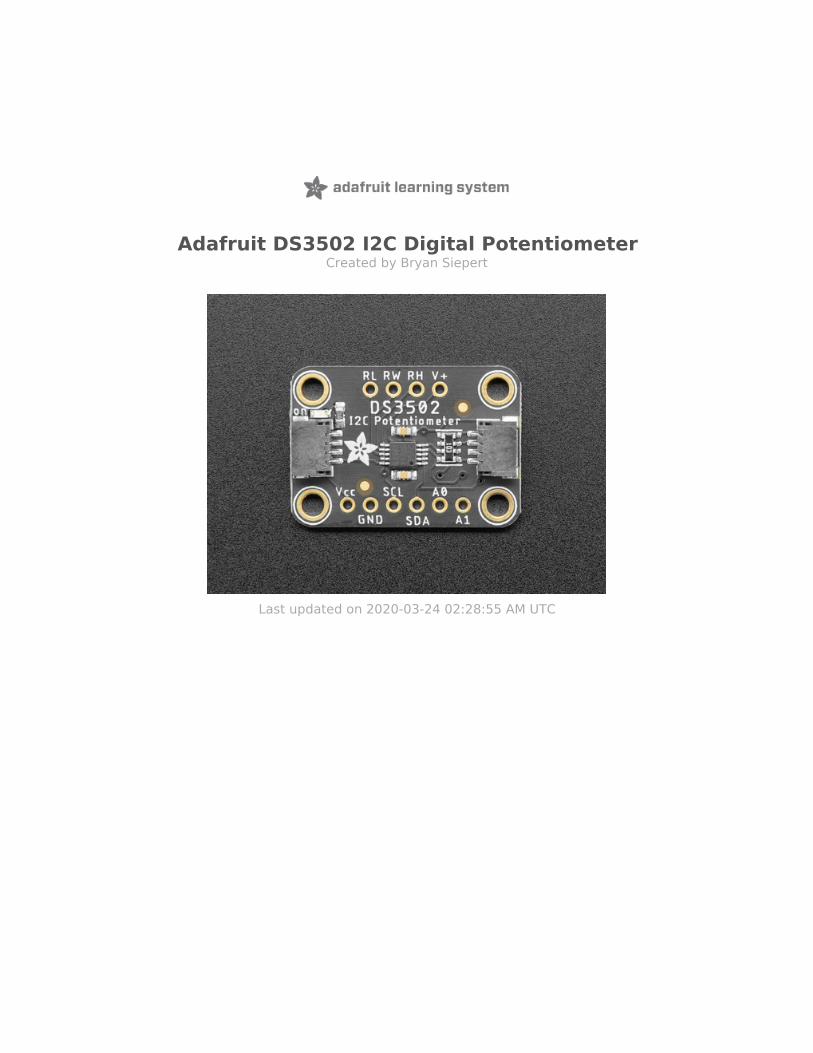
Adafruit DS3502 I2C Digital PotentiometerCreated by Bryan Siepert
Last updated on 2020-03-24 02:28:55 AM UTC

Overview
If you're a person like me that gets exhausted turning knobs all day, the DS3502 is just the ticket to calm all your knob-turning related troubles. Instead of having to turn knobs with your HANDS like an ANIMAL, the DS3502 I2C DigitalPotentiometer allows you to let your microcontroller adjust the resistance for you! Now you can free your hands to spinyour fidget spinner or or eat a slice of pizza while you're on the phone. Talking over an I2C bus, your Arduino,CircuitPython board, or Python powered computer can talk to the DS3502 and tell it to vary its resistance at your beckand call.
© Adafruit Industries https://learn.adafruit.com/ds3502-i2c-potentiometer Page 3 of 17

Working with the DS3502 is easy as an I2C controllable pie. We've put it on a breakout PCB with the required supportcircuitry and SparkFun qwiic (https://adafru.it/Fpw) compatible STEMMA QT (https://adafru.it/Ft4) connectors to allowyou to use it with other similarly equipped boards without needing to solder. This handy little helper can work with 3.3Vor 5V micros, so it's ready to get to work with a range of development boards. The DS3502 is a simple chip that doesone thing well and so it's very easy to work with. Wire it up and set the value for the wiper, thats it. To makethings even easier we've gone and written Arduino and CircuitPython/Python 3 drivers to simplify interfacing with yournew knob-replacing friend.
"OK, this thing sounds great. Give me some details" you say. OK then, here you go: The wiper value is a 7-bit numbermeaning there are 128 possible levels of resistance to choose, from 0-10K ohms. You can even set a default value thatwill be set on power up. The analog voltage controlled can be from 4.5-15.5V. Additionally you can use the addressjumpers or pins to set the I2C address to one of four values, allowing you to have four DS3502s on the same I2C bus.
© Adafruit Industries https://learn.adafruit.com/ds3502-i2c-potentiometer Page 4 of 17

Pinouts
Power Pins
The sensor on the breakout requires between a 2.7V and 5.5V, and can be easily used with most microcontrollers froman Arduino to a Feather or something else.
Vcc - this is the power pin. To power the board, give it the same power as the logic level of your microcontroller -e.g. for a 5V micro like Arduino, use 5VGND - common ground for power and logic
I2C Logic Pins
SCL - I2C clock pin, connect to your microcontrollers I2C clock line. The logic level is the same as Vcc and it hasa 10K pullup already on it.SDA - I2C data pin, connect to your microcontrollers I2C data line. The logic level is the same as Vcc. and it has a10K pullup already on it.STEMMA QT (https://adafru.it/Ft4) - These connectors allow you to connectors to dev boards with STEMMA QTconnectors or to other things with various associated accessories (https://adafru.it/Ft6)
Resistor Pins
RL is the Low Terminal of the potentiometer, often connected to ground.RW is the wiper of the potentiometer. As the wiper value is adjusted via I2C, the resistance between RW andRL/RH changes RH is the High Terminal of the potentiometer, often connected to your high voltage source.V+ is the wiper bias pin and is used to bias the gates of the MOSFETs that are responsible for changing theresistance between RW and RH or RL. If the voltage at RH is higher than VCC, V+ must be at the same or highervoltage than RH. By default this is connected with a jumper to RH but you can cut the solder jumper and wire it
© Adafruit Industries https://learn.adafruit.com/ds3502-i2c-potentiometer Page 5 of 17

directly
Extra Pins
A0 and A1 - These are the address select pins.
Since you can only have one device with a given address on an I2C bus, there must be a way to adjust the address ifyou want to put more than one DS3502 on a shared I2C bus. The A0/A1 pins set the bottom two bits of the I2Caddress. There are pull-down resistors on the board so connect them to VDD, you can solder the back jumpers or wirethem on a breadboard, to set the bits to '1'. They are read on power up, so de-power and re-power to reset the address
The default address is 0x28 and the address can be calculated by 'adding' the A0/A1 to the base of 0x28
A0 sets the lowest bit with a value of 1, and A1 sets the middle bit with a value of 2. The final address is 0x28 + A1 +A0.
So for example if only A0 is tied to VDD, the address is 0x28 + 1 = 0x29If only A1 is tied to VDD, the address is 0x28 + 2 = 0x2AIf A1 is tied to VDD and A0 is tied to VDD, the address is 0x28 + 2 + 1 = 0x2B.
© Adafruit Industries https://learn.adafruit.com/ds3502-i2c-potentiometer Page 6 of 17

© Adafruit Industries https://learn.adafruit.com/ds3502-i2c-potentiometer Page 7 of 17

Arduino
Wiring
Wiring the DS3502 to communicate with your microcontroller is straight forward forward thanks to the I2C interface.For these examples we can use the Metro or Arduino to measure the voltage changes as the DS3502 adjusts itsresistance. The instructions below reference a Metro (https://adafru.it/METROXMETR), but the same applies to anArduino
Connect the Metro 5V to VCC on the DS3502
Connect GND on the Metro to GND on the
DS3502
Connect the SCL pins on the Metro and DS3502
Connect the SDA pins on the Metro and DS3502
Connect RL to GND
Connect RH to Metro 5V
Connect RW to the A0 pin on the Metro, to allow
us to measure the voltage
Library Installation
Once wired up, to start using the DS3502, you'll need to install the Adafruit_DS3502 library (https://adafru.it/Ft7). Thelibrary is available through the Arduino library manager so we recommend taking that approach.
From the Arduino IDE, open up the Library Manager:
Click the Manage Libraries ... menu item, search for Adafruit DS3502, and select the Adafruit DS3502 library and clickInstall:
© Adafruit Industries https://learn.adafruit.com/ds3502-i2c-potentiometer Page 8 of 17

Follow the same process to install the Adafruit BusIO library.
Load Example
Open up File -> Examples -> Adafruit DS3502 -> ds3502_test and upload to your Metro wired up to the DS3502breakout as shown above. Once you upload the code, you will see the wiper settings and measured voltage beingprinted when you open the Serial Monitor (Tools->Serial Monitor) at 9600 baud, similar to this:
Example Code
The following code is part of the standard library and illustrates the basic function of using the variable resistance ofthe DS3502 to change the voltage measured at pin A0:
Temporarily unable to load content:
© Adafruit Industries https://learn.adafruit.com/ds3502-i2c-potentiometer Page 9 of 17

Arduino Docs
Arduino Docs (https://adafru.it/FrN)
© Adafruit Industries https://learn.adafruit.com/ds3502-i2c-potentiometer Page 10 of 17

Python &CircuitPython
CircuitPython Microcontroller Wiring
Wiring the DS3502 to communicate with your microcontroller is straightforward thanks to the I2C interface. For theseexamples, we can use a Metro or a Feather to measure the voltage changes as the DS3502 adjusts its resistance. Theinstructions below reference a Feather (https://adafru.it/Cmy), but the same applies to a Metro.
Connect the Feather 3.3V to VCC on the DS3502
Connect GND on the Feather to GND on the
DS3502
Connect the SCL pins on the Feather and DS3502
Connect the SDA pins on the Feather and
DS3502
Connect RL to GND
Connect RH to Feather 3.3V
Connect RW to the A0 pin on the Feather, to allow
us to measure the voltage
Python Computer Wiring
Since there's dozens of Linux computers/boards you can use we will show wiring for Raspberry Pi (https://adafru.it/scY).For other platforms, please visit the guide for CircuitPython on Linux to see whether your platform issupported (https://adafru.it/BSN).
Here's the Raspberry Pi wired with I2C:
Pi 3V3 to sensor VIN
Pi GND to sensor GND
Pi SCL to sensor SCL
Pi SDA to sensor SDA
Pi GND to sensor RL
Pi 3V3 to sensor RH
Multimeter Positive Lead to sensor RW
Multimeter Negative Lead to sensor GND
Note that because the Raspberry Pi does not include any pins with analog to digital converters (ADCs) to read thevoltage that will change on the DS3502's RW pin, you will need to use a multimeter to measure the voltage betweenthe RW pin and GND.
© Adafruit Industries https://learn.adafruit.com/ds3502-i2c-potentiometer Page 11 of 17

CircuitPython Installation of DS3502 Library
You'll need to install the Adafruit CircuitPython DS3502 (https://adafru.it/Ft8) library on your CircuitPython board.
First make sure you are running the latest version of Adafruit CircuitPython (https://adafru.it/Amd) for your board.
Next you'll need to install the necessary libraries to use the hardware--carefully follow the steps to find and install theselibraries from Adafruit's CircuitPython library bundle (https://adafru.it/uap). Our CircuitPython starter guide has a greatpage on how to install the library bundle (https://adafru.it/ABU).
For non-express boards like the Trinket M0 or Gemma M0, you'll need to manually install the necessary libraries fromthe bundle:
adafruit_ds3502.mpyadafruit_bus_deviceadafruit_register
Before continuing make sure your board's lib folder or root filesystem has the adafruit_ds3502.mpy,adafruit_bus_device, and adafruit_register files and folders copied over.
Next connect to the board's serial REPL (https://adafru.it/Awz)so you are at the CircuitPython >>> prompt.
Python Installation of DS3502 Library
You'll need to install the Adafruit_Blinka library that provides the CircuitPython support in Python. This may alsorequire enabling I2C on your platform and verifying you are running Python 3. Since each platform is a little different,and Linux changes often, please visit the CircuitPython on Linux guide to get your computerready (https://adafru.it/BSN)!
Once that's done, from your command line run the following command:
sudo pip3 install adafruit-circuitpython-ds3502
If your default Python is version 3 you may need to run 'pip' instead. Just make sure you aren't trying to useCircuitPython on Python 2.x, it isn't supported!
CircuitPython Usage
To demonstrate the usage of the potentiometer we'll initialize it and set the wiper value to change the voltage onthe WH pin. We will then use the A0 pin to take an analog reading of the voltage on the WH pin.
Run the following code to import the necessary modules and initialize the I2C connection with the potentiometer:
Because of hardware differences, Python Computer users should follow the "Python Usage" examples in the next section�
© Adafruit Industries https://learn.adafruit.com/ds3502-i2c-potentiometer Page 12 of 17

from time import sleepimport boardimport adafruit_ds3502from analogio import AnalogIn
i2c = board.I2C()ds3502 = adafruit_ds3502.DS3502(i2c)wiper_output = AnalogIn(board.A0)
With the driver initialized, we can the set the wiper value, take an ADC reading to measure the voltage, and thenconvert the raw ADC value to a human-readable value
ds3502.wiper = 127print("Wiper set to %d"%ds3502.wiper)voltage = wiper_output.valuevoltage *= 3.3voltage /= 65535print("Wiper voltage: %.2f V"%voltage)
We can then change the wiper value and take another reading to see how the resulting voltage on the RW pin haschanged
ds3502.wiper = 63print("Wiper set to %d"%ds3502.wiper)voltage = wiper_output.valuevoltage *= 3.3voltage /= 65535print("Wiper voltage: %.2f V"%voltage)
Full CircuitPython Example Code
© Adafruit Industries https://learn.adafruit.com/ds3502-i2c-potentiometer Page 13 of 17

Temporarily unable to load content:
Python Usage
Because the Raspberry Pi and many other similar devices do not include the hardware for measuring analog voltages,you will have to use a multimeter to measure the voltage on the RW pin.
To start, similar to above we will import the needed modules and initialize the driver
from time import sleepimport boardimport adafruit_ds3502
i2c = board.I2C()ds3502 = adafruit_ds3502.DS3502(i2c)
Once the driver has been initialized, we can use it to set the value of the wiper
ds3502.wiper = 127
You can then use your multimeter or other voltage measuring device to check the voltage across GND and RW. Itshould be the same as the voltage on the RH pin which will be the voltage level of your device, most likely 3.3V
Next, change the wiper value again and measure the voltage on the RW pin
ds3502.wiper = 63
The voltage on the RW pin should be approximately half of the voltage at the RH pin, likely around 1.6V
Full Python Example Code
Temporarily unable to load content:
© Adafruit Industries https://learn.adafruit.com/ds3502-i2c-potentiometer Page 14 of 17

Python Docs
Python Docs (https://adafru.it/FiU)
© Adafruit Industries https://learn.adafruit.com/ds3502-i2c-potentiometer Page 15 of 17

Downloads
Files
DS3502 Datasheet (https://adafru.it/Ft9)EagleCAD files on GitHub (https://adafru.it/Fta)3D CAD files on GitHub (https://adafru.it/FGL)Fritzing object in Adafruit Fritzing Library (https://adafru.it/Ftb)
Schematic
Fab Print
© Adafruit Industries https://learn.adafruit.com/ds3502-i2c-potentiometer Page 16 of 17

© Adafruit Industries Last Updated: 2020-03-24 02:28:55 AM UTC Page 17 of 17