Embed Size (px)
Citation preview
AD/A-C04 013
DESIGN CONCEPTS FOR HELICOPTER PALLETS AND GONDOLAS
C. Weber, et al
Parsons of California
Prepared for:
Army Air Mobility Research and Development Laboratory
Novembe r 1 974
DISTRIBUTED BY:
Mi] National Technical Information Service U. S. DEPARTMENT OF COMMERCE
f^WÜJWSJW^WW^Wf^ H.i k "WWi MMMMMi
UNCLASSIFIED «CCuniTV CLMMflCATlON O» TNIt #•«« (•*« D«« BnttM«
REPORT DOCUMENTATIOK PAGE ;T
RtAD mrntucTioNs ■trOWK COMPLBTWG rOKM
NICmilMT'l CATAkO« HlÜSiiM U»olV SDSm
USAAMRDL-TR-74-91
t. «OVT ACCIMWM HO.
AM. DESIGN CONCEPTS FC« HELICOPTER PALLETS AND GONDOLAS
■. TVI>I or'nt-tnr • »KMoocovinto
FINAL
» «uTMOur*)
C. WEBER, R. YUUNG
k, »CnFOMUNOCNO. ItC^OMT NUMKN
■. CONTMACT OH OMANT NUMaCMT*)
DAAJ02-73-C-0058
i«. PHOOMAM CLCMCMT.nnojtcr, r*«« AMA • •OMK UNIT NUMOtN*
TASK 1F162203AA3303
• PIMrOMMHO ONOANItATION NAMt ANO AOOHCtl
PARSONS OF CAIJFORNIA 3437 S. AIRPORT WAY, P. 0. BOX 6189 STOOCTON, CALIFOR>'IA 95206
< I. COMTMLLINO OPfICf MAMI ANO AOOMM
EUSTIS DIRECTORATE, U. S. ARMY AIR MOBILITY RESEARCH AND DEVELOPMENT LABORATORY FORT EUSTIS, VIRGINIA 23604
II. NKMNT OATI
November 1974 it.
II SSNTTOGNS SIINTV NAMC • Aoemtwn «Mmni m» CmSSnSZoiSZ») Jlk.
ii. iccumrv CLAM, (»t mi» n^wi)
UNCLASSIFIED TC-ö^j^cÄTi ON/DOWNONAOINO
I«. onTmaurioN ITATIMINT CI Sü« HOSii
Approved for public release; distribution unlimited.
IT OtlTNiauTION ITATIMtNT (9l *>• tttmmt mltm* m WM» W, If mMmml 5=155=5 ^ D D C r:"-""',-"; ":-:'7n nrp
.l/'-M 27 19T3 II Wn^LlMINTANV NOT«
'II '
D '•• RCV «ONOI (CmMmu m tmr
HELICOPTER EXTERNAL, CARGO SLUNG LOADS GONDOLA
i «M* If m—m—tr anä UmiHr If UM» mmtm)
SLINGS TOP LIFTING ANSI/ISO AREA DENSITY
CUBE DENSITY
PRICES SUBJECT TO CHANGE 10. AMTNACT (CmHim» m mrmt t»m II MMMCT m4 Itmlltr If MM* mm»*)
This report presents the results of the design concepts investigation and pre- liminary design of externally suspended cargo pallets and/or gondolas to be utilized with the CH-47, (31-54, and HLH helicopters. Results of the investi- gation demonstrated that gondolas of two sizes could be coupled to develop full payload capacity of any of the three helicopters. The basic gondola was right rectangular to accommodate vehicles and equipment or break-bulk cargo if required. The investigation and supporting analyses eliminated pallets with lifting points at the base which make it both unstable and structurally
00,:S-nU71 COtTtOH Or I NOV •• I« OMOUlTt
R«pi-iduc«d by
NATIONAL TECHNICAL INFORMATION SERVICE
U S Dcpaitmanl of Commarce Sprlngd.ld, VA. 22151
UNCLASSIFIED MCumTV CLAIIiriCATION or TMII PAOC (Wttmn Dim ««MM«
UNCLASSIFIED HCUWITY CLMwriOTiow o> Tmj »gtnww p—
inefficient. Therefore, pallets were not considered as a viable design concept. The gondola provides compatibility with ANSI/ISO geometry and can be transported with slings or other load acquisition equipment. 'The gondola may be introduced at any segment of the through-put supply system to transport vehicles and equipment or break-bulk cargo as required.
UNCLASSIFIED neuNiTr ei.*Mtf)e*TiOM or THIS PMwwttm om ammm
mcoiiw jjr
NTH
IW
^INNOMCEa
JISTiriCAIHM .
Mitt SKtlW ^ „
w EUSTIS DIRECTORATE POSITION STATEMENT m
—^This project generated conceptual designs and preliminary design drawings of a gonodla system selected as the most re- sponsive to support the mission of Army cargo helicopters. The contractor relied or reference material pertaining to -logistics, field operational requirements, Interviews with prime manufacturers of aircraft, and commercial terminal and helicopter operators. In-depth analyses were conducted to determine aerodynamic, material, structural, performance, and logistic factors and intermode compatibility. Preliminary design drawings generated under this program represent a new approach to a flexible, effective gondola system.
This directorate does not concur with the downward design load factor of 3.0 used in developing structural criteria. A factor of 2.8 is considered to be more realistic In view of guidelines determined by recently completed tests.
Results of this contract are being used to establish programs that will Include fabrication of experimental gondola assemblies designed to revised load factors for static/ground testing and flight evaluation.
Mr. S. G. Rlggs, Jr., of the Military Operations Technology Division served as Project Engineer for this effort.
DISCLAIMERS
Tbt finding« in this rtport »rt not to b« construed as an official Department of the Army position unless so designated by other authorized documents.
When Government drawings, specifications, or other data are used for any purpose other titan in connection with a definitely related Government procurement operation, the United States Government thereby inci'rs no responsibility nor any obligation whatsoever; and the fact that the Government may have formulated, furnished, or in any way supplied the said drawings, spaclflcationk, or other data is not to be regarded by implication or otherwise as in any manner licensing the holder or any other person or corporation, or conveying any rights or permission, to manufacture, use, or sell any patented Invention thet may In any way be related thereto.
Trade names cited in this report do not constitute an official endorsement or approval of the use of such commercial hardware or software.
DISPOSITION INSTRUCTIONS
Destroy this report when no longer needed. Do not return It to the orlginetor.
///
L
tMm^miwm-'mimimimm'
TABLE OF CONTEOTS
PACE
LIST OF ILLUSTRATIONS 6
LIST OF TABLES 9
imODUCTION 10
Objective 10
Requirements 10
Helicopter Characteristics 12
CH-47 12
CH-54 12
HLH 12
CARGO CHARACTERISTICS 18
Size 13
Cube and Weight 18
Area Density 19
GONDOLA PERFORMANCE 23
Sizing Methodology 23
Load Capacity 23
Cubic Capacity 23
Area Density 24
Payload Effectiveness 25
STABILITY 26
Towing Stability 26
Vertical Drag 31
CH-47 32
Table of Contents (continued)
PAGE
CH-54 35
Hm 36
Lift Point Stability 39
Vertical Bounce 44
Materials and Method of Construction 44
Methods of Construction 45
Materials 46
Strength-to-Weight Ratios 47
Cost/Strength Ratio 49
Composite Rating 49
SUPPORT EQUIPMENr 53
Loading 53
Cargo Restraints 55
Ground Mobility 55
Helicopter Attachment 55
Single Point 55
Four Point 58
Two Point 58
LOGISTICAL AND TECHNICAL MISSION REQUIREMENTS 59
Helicopter Mission 59
In Flight 61
Returns 61
Terminal Requirements 61
i*,«m*.im-<WBi
Table of Contents (continued)
PAGE
Intermodal Requirements 63
OPERATIONAL SUITABILITY" 66
utilization 66
Reliability-Maintainability 68
Intermodal Damage 69
Terminal and Yard Damage 70
Environment 70
PERSONNEL EFFECTIVENESS 71
DESIGN CONCEPTS 72
STRUCTURAL ANALYSIS AND LOADING CRITERIA FOR GONDOLA 79
Loads 79
Criteria 82
3.0 G Helicopter Lift, 40-Ft Gondola 86
SINGLE-POINT SLING LOADING AND INDUCED 87
Gondola Loads 87 ]
: 3.0 G Helicopter Lift, 20-Ft Gondola 88
60%:40l Load Distribution 89
1.25 G Forklift, 40-Ft Gondola 90
.6 G Side Sway - Helicopter, 40-Ft Gondola/Far Side 91
.6 G Side Sway - Helicopter, 40-Ft Gondola/Near Side 92
End Sway . 6 G - Helicopter, 40-Ft Gondola 93
Stacking Condition 95
Sunmary - Superstructure Limit Brace Loads 96
Unit Load Distribution/Deck to Crossbeams/20-Ft Gondola 97 i
3
Table of Contents (continued)
PAGE
IMit Load Distribution/Deck to Crossbeams/lO-Ft Gondola 98
Unit Load Distribution/Side Beams to Superstructure/ 20-Ft Gondola "
Unit Load Distribution/Side Beams to Superstructure/ 10-Ft Gondola 100
40-Ft Gondola Side Beam - Load Distribution 101
Side Beam Analysis 102
Margin of Safety 107
Typical Lug and Pin Analysis 109
Shear Out-Bearing Analysis 110
Compression Bearing HO
Pin Shear HO
Cone Bearing - Comer Stanchion I11
Joint Analysis - Side Beam to Comer Casting 112
Attachment H3
Shear 113
Bearing H3
Joint Analysis - End Beam to Comer Casting H4
M54 Truck on 40-Ft Gondola With M149 2 Wheel Trailer 116
CONCLUSIONS 128
RECOfCNnATIONS I29
REFERENCES 130
APPENDIXES 132
A. Analyses of Other Gondola Concepts I32
■MgHM k^ffli" .
Table of Contents (continued)
PAGE
B. Gondola Sizing Methodology 141
C. Survey of Technology 161
LIST OF SYMBOLS 171
LIST OF ILLUSTRATIONS
FIGURE PAGE
1 ai-47 Helicopter 13
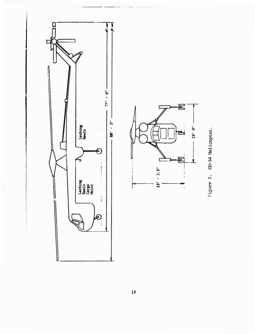
2 CH-54 Helicopter 14
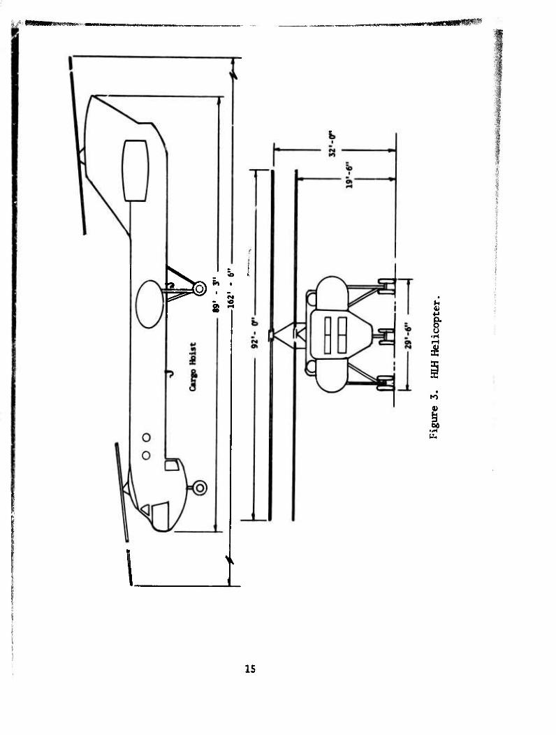
3 mi Helicopter 15
4 Load Profile Drag Forces 27
5 Minimum Drag Angles 28
6 Vertical Drag CH-47 33
7 Vertical Drag (H-54 37
8 Vertical Drag Hlfl 38
9 Pallet Instability 40
10 Allowable Flight Speed for Pallets With Varying Area Density and Load Factor 42
11 Strength-to-Weight Ratio 48
12 Cost-to-Strength Ratio 50
13 Typical Logistics Interfaces for Gondola Utilization 60
14 Gondola Utilization Flow Diagram 62
15 10-x-20-x-10-Ft Coupled Gondola Assembly 80
16 Brace Structure Loading (3G) 86
17 Sling Attachment Angles 87
18 Brace Structure Loads (Center Section) 88
19 60%:40% Load Distribution 89
20 Forklift Loading 90
21 Side Sway Loading - Far Side 91
22 Side Sway Loading - Near Side 92
23 End Sway Loading (.6G) 94
FIGURE PAGE
24 Shear and Moment Diagram - Deck to Crossbeam, 20-Ft Gondola 97
25 Shear and Moment Diagram - Deck to Crossbeam, 10-Ft Gondola 98
26 Shear and Moment Diagram - Side Beams, 20-Ft Gondola 99
27 Shear aid Moment Diagram - Side Beams, 10-Ft Gondola 100
28 Shear and Moment Diagram - Forklifting, 40-Ft Gondola 101
29 Tineway Analysis 102
30 Gondola Loaded With M-54 Truck and M-149 Trailer 119
31 Truck Front Wheel Shear-Moment Distribution on Crossbeams .. 120
32 Shear-Moment Distribution on 10-Ft Side Beam For Trailer Axle Load 123
33 Shear-Moment Distribution on 20-Ft Side Beam For Truck Front Wheel Loading 124
34 Shear-Moment Distribution on 10-Ft Side Beam For Truck Front Wheel Loading 125
A-l Folding Gondola - 20-Ft I33
A-2 Folding Base, 8-x-8-Ft 134
A-3 Soft Base Gondola, 8-x-20-Ft 135
A-4 Rigid Base Pallet Cell Gondola 139
B-l Area Density Variation 142
B-2 Cubic Gondola Weight Ratio (Welded) 143
B-3 Gondola Concept Weight Variance 144
B-4 Stanchion Weight Variation 145
B-5 Side Bracing Weight Variation 146
B-6 Floor Beam Weight Variation 147
-S ■', j I
FIGURE PAGE
B-7 Floor Grate Weight Variation 148
a-8 Gondola Height-to-Length Ratio vs. Weight 149
B-9 Typical Cube and Over-Cube Gondola Configurations 150
B-10 Corapar *ve Tare Weight of Cube vs. Over-Cube Gondolas 151
fföfcOtfitäp-yr ■ - ■, _ iiiwMimii»» m ' «rnvr- -1 -- - -mmm
LIST OF TABLES
TABLE KAHB
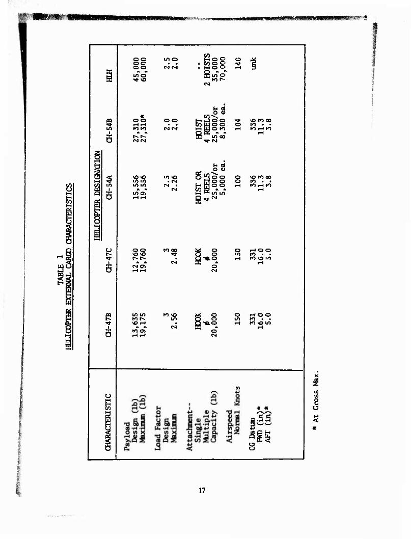
1 Helicopter External Cargo Characteristics 17
2 Transportability of Vehicles 21
3 (H-47 Cargo Containers Orientated Fore and Aft 32
4 CH-47 Cargo Containers Orientated Sideways 32
5 CH-54 Cargo Containers Orientated Fore and Aft 36
6 HIH Cargo Containers Orientated Fore and Aft 39
7 Material - Handling Vehicles 54
8 External Cargo-Handling Materials 56
9 Internal Cargo Restraints Materials 57
10 Intermodal Cargo Volumes 64
11 Intermodal Dynamic Load Factors 65
12 Operational Suitability Helicopter Gondola Utilization 67
13 Design Concepts 72
14 Composite Evaluation Matrix 78
15 Gondola Limit Design Load Factor 79
16 Vehicle Axle Loads 81
17 Superstructure Brace Limit Loads 96
18 Summary of Brace Structure Column Analysis for Superstructure I08
A-1 Loads and Member Si zing, Soft-Base Gondola ^ 36
A-2 Load and Member Sizing, Rigid-Base Pallet Cell Gondola 140
B-l Cubic Design Sunmary 160
C-l Pallet Gondola Suppliers ^
C-2 Commercial Helicopter Operators ^69
INTRODUCTION
A parametric investigation of the performance requirements for externally suspended helicopter cargo was conducted to generate pallet or gondola concepts. Design concept? were developed to satisfy the salient per- formance parameters and operational interfaces. The program to fulfill the objectives was conducted by th* following tasks:
1. Parametric Study (Helicopter, Cargo, and Interface)
2. Survey of Technology (Equipment Suppliers and Commercial Operators)
3. Design Concepts (Preliminary Design)
Increased uso of the helicopter in transporting vehicles, equipment, and break-bulk cargo as an externally attached load aas identified the need for improved cargo-carrying support equipment.
Through the investigation and supporting analysis, the pallet concept with loa^ arnni «itinn nmnts at nr npar ha<;p wa«; pi iminjitPfl rlnp tn it inherent ith load acquisition points at or near base was eliminated due to its nherent flight instability and lack of structural efficiency.
OBJECTIVE
The objective of this investigation was to identify the requirements and interfaces to optimize t'.j gondola concept and to initiate preliminary design. Subsequent to the investigation and design concept phase, the preferred concept was developed through preliminary design. The design requirements were developed to accommodate the CH-47, CH-54, and HLH to transport vehicles and equipment and break-bulk cargo as required. In addition, the gondola would provide the floor area and cubic capacity to develop full payload capacity of the three helicopters: CH-47, (H-54, and HLH. These objectives were achieved with a preferred concept which utilizes 10-ft and 20-ft gondola units which may be coupled to obtain a 40-ft gondola or used individually with a payload capacity range of 15,000 to 60,000 lb. The coupled 40-ft and individual 20-ft units are compatible with International Standard Organization geometry for land and sea operations.
REQUIREMENTS
The gondola design approach concepts were primarily predicated on the utilization of the helicopter as a principal mover and its attendant inter- face in the logistic supply line. While the gondola must satisfy the forward supply segment(s) of the distribution network, it should be com- patible with surface modes of transportation and in contingencies with fixed-wing aircraft.
10
Payload Effectiveness
The gondola design(s) must provide the payload capacity and volune to satisfy each of the three helicopters. Weight should be a minimum con- sistent with structural requirements.
Cargo To Be Transported
Cargo to be transported will consist primarily of vehicles and equip- ment with secondary capability to transport break-bulk cargo.
Attachment To The Helicopter
Slings or load acquisition devices shall be used to engage four lift points located above and outside the load center of gravity (CG).
Interface Compatibility
The gondola, while principally used attached to the helicopter, should be compatible with materials handling equipment except where such equipment is capacity limited. Corrpatibility shall be extended to other modes of transportation consistent with MILYAN and American National Standard Institute/International Standard Organization requirements.
Logistical and Technical Requirements
Logistic impact of the gondola is such that it can be introduced at any segment of the cargo distribution network. It shall provide maximum payload capacity of the helicopter and shall be compatible with surface and sea modes of transportation through all segments of the supply network.
Structural Requirements
The gondola shall withstand the static and dynamic forces encountered from helicopter transport. Additionally, it shall withstand the forces encountered from surface modes and terminal handling.
Stability
The gondola shall have four lift point attachments above and outside the center of gravity (CG) to preclude overturning when transported by heli- copter. It shall be compatible with single or multipoint suspension.
Construction
Construction shall be simple, low in cost, and n sistant to rough handling and environmental degradation when operating in ' limatic extremes.
11
Modularity
Gondolas should have the capability to be joined to acconroodate all three helicopters. The method of joining shall bt simple and require no special tools.
HELICOPTER CHARACTERISTICS
CH-47
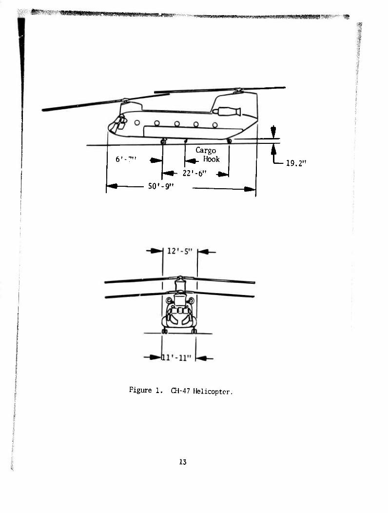
The CH-47B/C is a twin-rotor helicopter having internal as well as external cargo-carrying ability. The external cargo attachment is a single-point hook located at the underside of the fuselage. The power-actuated hook is on a load beam which permits lateral and longitudinal oscillations. The cargo hook fixed to the fuselage requires that personnel engage the external cargo between the load and the aircraft or use a guide pole from inside the aircraft, and this is undesirable from a personnel safety standpoint. However, we are unaware of any accidents experienced with this arrangement. The helicopter is shown in Figure 1, with data pertin- ent to the design of pallets/gondolas for the CH-47B/C sumnarized in Table 1.
CH-54
The CH-54 is a single-rotor helicopter which can utilize a cargo pod or external cargo hook/hoist available in both the A and B models. These ships are nearly identical in configuration. The B model has approximately 8,000 lb greater capacity than the A model, which for this study has the greatest impact. The ship will accept either four-point or single-point external load attachment. The four-point attachment can acquire a load with limited vertical travel with each point having either 5,000 or 8,300 lb capacity. The single-point attachment is accomplished with a cargo hook/hoist having a capacity of 25,000 lb. It is nonnally used to carry externally slung cargo rather than the four reel points. The reel points serve to acquire the cargo pod. The hoist has a useable length of 100 ft teminated at the hook, which is swiveled for 360° operation. Data pertinent to the design of pallets and gondolas for the CH-54A/B is sum- marized in Table 1.
HLH
Preliminary design of the helicopter is identified as a tandem-rotor air- craft equipped with a tandem hoist system to transport external cargo. Since the helicopter is in the preliminary design stages, complete defin- ition of the helicopter, including the external cargo system, is not avail- able. The principal design feature in addition to large payloa- capacity is the two-point hoist system. The two-point attachment should provide substantial yaw and pitch control of the load. Additionally, the hoist- ing capability will permit improved load acquisition since the hoisting cable would attach well below the aircraft. Data pertinent to the inter- face with the external pallet/gondolas is summarized in Table 1.
12
'•' 1,^m^':'mmm^^ m
Cargo i- Hook
ZZ'-V
- so'-g"
i i 19.2'
Figure 1. CH-47 Helicopter.
13
u 4) 4-»
I
5
a» u 3 05
14
8 r^ummmum^^
1
^t§)^: ' 8 1
\
I Ä
to
p
u.
15
-; ■:Äi.,;.!: .„_■■•';
A review of the external cargo characteristics of the three helicopters suggests that they may be categorized as medium and heavy load-carrying aircraft. The CH-47 and (H-54 helicopters are nearly identical except at alternate or maximum gross weight. Since the CH-54B is weight limited to 25,000 lb by the cargo hoist, they may be considered to be in the same capacity range. The HUH is approximately double the capacity of either of the other two helicopters. The alternate capacity could exceed 70,000 lb under limited operating conditions. However, it appears that normal external cargo deliveries will be made at less than 60,000 lb. Table 1 sunmarizes the characteristic data for each of the three heli- copters.
16
wmmmmxm vmimt v*&m
oo oo oo if> o
in O • • &joo ►H O O Q « « •p in o tot- CM
o 1
m
« oo i-HtH M tn
m m t». t^ N «M
OO • • CM CM
£ ÖS
loo >* VO »000 loo o ro • • OK» iH »O iH tO
m oo • CM
in i
0\0 m m m m * » m a>
m vo • CM
(M • CM
O S loo o \o to 00 loo o to • • 1 O O iH IO iH tO
m m CM
^ oo vOvO
«M 0%
to 00
CM
; o I o l'ÄO
o CM
O rH O O m to • • IH to \o m
5
in m to \o JKS O o rH O O to f~ in Q 0 m to • • »OfH • Q,«.o iH to om
» * CM Al * rH too» o r-tiH CM
V)
u t-H
« « I «
8
17
irv*-~ '■■'-
CARGO CHARACTERISTTCS
Cargo to be transported by helicopter shall include, but will not be limited to, that which is noncontainerizable; primarily, vehicles and equipment which cannot be stowed in closed containers. However, the gondola should accept break-bulk cargo for contingency missions. The principal cargo parameters which will impact design are as follows:
1. Size (length, width, and height)
2. Cube Density
3. Area Density
A listing of vehicles and equipment which might be transported as exter- nal cargo appears at the end of this section.
SIZE
Size of cargo to be handled must be considered for cube utilization. Ideally, the size of the cargo to be transported should fully utilize the cargo space of the pallet/gondola. In transporting cargo, this factor becomes quite unpredictable due to the varying package sizes. However, since the capacity of the gondola should provide for a load of 20,000, 30,000, or 60,000 lb, the cubic capacity becomes less critical for pack- age size consideration when bulk items are being transported. Size of the pallet/gondola is not so much a function of the crrgo item or package size but rather a size to develop full payload utilization of the helicop- ter. Since the helicopters considered herein have a capacity near 20,000 lb or greater, the size factor of items becomes secondary when compared to other interface size dimensions. While size factor of cargo may not be of primary concern, the transport of equipment and vehicles must be of concern in optimizing size. As the table indicates, the width, in some cases, is slightly greater than the nominal 8-ft highway and ocean ship cell dimension. Since these di- mensions are extremes, it is possible to transport such equip- ment with local projections when using a porous sided gondola. Another important difference to be considered for vehicle loads is the concentration of loads from the axles. Con- centrated axle or wheel loads would require considerably more structure locally. It is then advisable to design treadways or local reinforced structures for high-density axle loads. Therefore, cargo size becomes more important when transporting vehicles and outsized equipment than to accommodate standard sizes to a practical extent.
CUBE AND WEKHT
Confined cargo delivered in containers, palletized and packaged, has a range of density from 5 to 40 lbs/cu ft. This does not exclude the pos- sibility that heavier or lighter cargo will be experienced. However, historical data on overseas shipment since 1952 suggest that 90% of all
18
cargo will have a cubic density of 40 lb or less. The 20-ft containers used in ocean shipment are generally accepted to have a cargo capacity of 40,000 lb. The typical cube of such a container is approximately 1100 cu ft. If the cargo space and capacity is fully utilized, the resulting cargo density would be as follows:
Density « 4^QQ
0 = 36.36 Ib/cu ft
Data on the actual cargo densities as reported by Maritime Administration for a typical quarterly period is as follows:
North Atlantic Inbound 22.2 Ib/cu ft
North Atlantic Outbound 19.3 Ib/cu ft
Pacific Inbound 19.3 Ib/cu ft
Pacific Outbound 23.4 Ib/cu ft
The data1 shows that 21.0 Ib/cu ft is an approximate value for cargoes moving in both directions across the Atlantic and Pacific.1 These den- sities are based on containerized cargo for the standard 3-x-8-x-20-ft container. Using the average cube density of 21.0 cu ft and available cubic capacity of 1100 cu ft, results in an average pay load of 23,100 lb. This payload is approximately 3,000 lb over the capacity of the (H-47B/C and 4,000 lb below the Qi-54B capacity. Experience from WW-II and the Korean engagement suggests a mean density of 22.6 Ib/cu ft.2 Since this time, equipment and other cargo have a trend toward smaller and lighter configurations and air resupply. It would appear from the daf that an average cube density of 20.0 Ib/cu ft would suffice for predicting cubic density of the pallet/gondola.
AREA DENSITY
The parameter that is unique to aircraft external cargo is area density (AjO, which is defined as the weight of the load (W.) and the maximum frontal area (A^l that the load can have in an attitude which might be
i Berger, S., Heider, F., Lechus, J., Ralston, R., Watson, I., A CRITICAL ANALYSIS OF TOE STATE OF THE ART IN CONTAINER!ZATI0N; Control Systems Research Inc., United States Army Mobility Equipment Research and Dev- elopment Center, Ft. Belvoir, VA, November 1970 AD-877259L.
2 Wood, Charles, W., Watts, John H., Lucas, Robert H., DESIGN CRITERIA TECH- NICAL CHARACTERISTICS, AND DESIGN CONCEPTS IOR AN AIR TRANSPORTABLE CON- TAINER, Arthur D. Little, Inc.,; USAAML Technical Report 65-36, United States Army Aviation Materiel Laboratories, Fort Eustis, VA, June 1965 AD-619158.
19
imm*&v»*?>w«im*m,<iitii>mmr-*»:-'t- '■••»-■
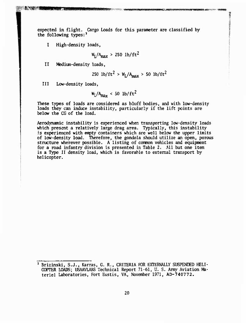
expected in flight. Cargo Loads for this parameter are classified by the following types:3
I High-density loads,
VW > "0 lb/ft2
II Medium-density loads,
250 lb/ft2 > WL/A,^ > 50 lb/ft2
III Low-density loads,
Wx < 50 lb/ft2 These types of loads are considered as bluff bodies, and with low-density loads they can induce instability, particularly if the lift points are below the CG of the load.
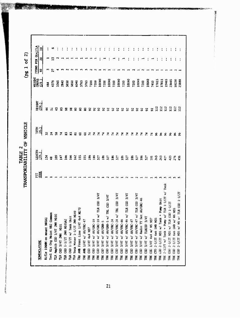
Aerodynamic instability is experienced when transporting low-density loads which present a relatively large drag area. Typically, this instability is experienced with empty containers which are well below the upper limits of low-density load. Therefore, the gondola should utilize an open, porous structure wherever possible. A listing of common vehicles and equipment for a road infantry division is presented in Table 2. All but one item is a Type II density load, which is favorable to external transport by helicopter.
3 Brizinski, S.J., Karras, G. R., CRITERIA FOR EXTERNALLY SUSPENDED HELI- COPTER LOADS; USAAVLABS Technical Report 71-61, U. S. Army Aviation Ma- teriel Laboratories, Fort Eustis, VA, November 1971, AD-740772.
20
FIPiBf,*■ *«;v**mmm WWI'JIBiMWJIW-WIIH.W MMMMMWMM—MW» "■"' - -
CM
o
oo
u
rg s
K> r- ««r rs|fS|fMK1tOfMrM^(N)H«>JrHr>Jf-H CM^HfMi-trsliHi-lr-li-tF-trH
5w5 | \o m O I-IQ cnl ^r r-. >o ^ Ul fi -41 00 K> O 00 So ^-1 ^ <» ^ rj
o o o »o o o ^ o ^t >o sO o o o ~ r-- r- rj fM o H> K) fs, IS. «H
o o o o o in in in o ^t O Tt- o ** o ■**■ o *t O *-< rH vO *o K1 flO
o o o o o o o m 00 00 ^t o o o rsi o rg o ^r r- r- K) K> on K> r- i-H 1^ f-t r^ .-1 t-- iH r-- r-( r- iH tH r4 (Nl rH r^j
^■^Kiioooaoo^OiNrMrjfsjrsjrMrMrjr-irgrgfsirg rg ,Tl/*^00OVO*fl00000Ot0»Ctff>C»CTtO>CnO*O^0tOO^ w
rj rvi (N rsi rj rg
torvjinr^aooooo^or-'-r^r-r- i^i^i^r--i^-r--r-i^r-i^a»o^aiCT»a>a)
Zl^- a»i^.-O'0r»jinino»c
■^-1 f-(^rHr-ti-4<HiHf-t(-ti-4r-i
tn 8|
r^oOrMOOrgOOfSiOOrvioO*^ O^O^OfN rsir^lO
«-t ro to Ki ro Ki »o
21
CM
o
(X
fM O
Sri
■H rti-IKlrOI-JCMlO tO CN4 1^ r4 <M M
SE CA r-J O I/) 1/1
1U B 31 « S>l/liHF-l<M»li-IIMiHfMi-<fM<M«'n
Id
■g 1 ( i
t t t t
H
1 l-l
' t t
1
Ü IO p-t i-4 «H t-^ i
ui m »o to r^ O ä ^
o s ^ R x> irt « f«J <M Kl •» o
«NfMiHiHi^tHtHfH •H oH O t fH
pHF-tr-tt-Hi-tKtK) IO K) Kl *>H " ^»O
§ rv t^. to »o -o Ot ot «o >o «o
^If-irslfM^irop-tiMr^fsJCM
gggg liil
oo
t 8.
ü =
22
««^^«»^■■■•tfWiWSttwsiBfsmws^^
GONDOLA PERFORMANCE
SIZING IdHODOLOGY
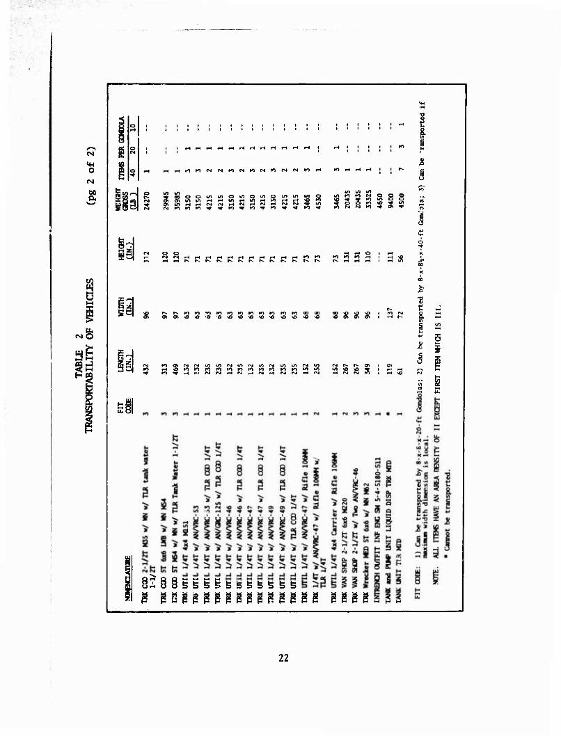
Sizing methodology is predicated on providing intermodal ccmpatibility and sufficient cubic capacity to transport vehicles and equipment. Several studies have been conducted on sizing optimization for efficient use of volume payload or a composite utilization. The 8-ft gondola width allows the transporting of 75% or more of the items listed in Table 2. These results also indicate that a gondola length between 400 and 500 in. would have more utility in transporting tactical vehicles and equipment than a shorter gondola. Therefore, it would appear that a wider and longer gondola would be best suited to the HLH than the medium helicopter. Additionally, the smaller gondola would transport the break-bulk items by realizing more efficient distribution in forward areas.
Load Capacity
Pal let/gondola performance can then be identified from the helicopter capacity and the cargo to be transported. As shown in Table 2, the two medium-lift helicopters have a maximum payload capability near 20,000 lb. with the (H-54B at 27,310 lb, and the Hlfl at 60,000 lb. To provide a 20,000-lb-capacity gondola for a helicopter load factor of 2.56 requires a structure that would carry a load which is near the capacity of the CH-54B (26,087 vs. 27,310)."^ This is 95% capacity of the 04-548 helicopter. From this aspect it does not appear feasible to have separate pallets/ gondolas for the CH-47 and CH-54 aircraft.
The HIÜ aircraft has approximately threefold the capacity of the other helicopters under consideration. This increased capacity suggested a significantly greater volume than required for the CH-47 and CH-54. It appears that the normal operable capacity for this ship is 60,000 lb with a load factor of 2.0. Therefore, considering both load capacity and dynamic load factor of the helicopters suggests two sizes of gondolas.
Cubic Capacity
Cubic capacity of the gondola should provide sufficient volume such that the helicopter will be operating at or near payload capacity most of the time. Previous studies of confined cargo suggest that a cubic density of 21.0 Ib/cu ft is average. Since trends are to lighter and smaller equip- ment and packaging, a cube density of 20.0 Ib/cu ft will be used to predict the volume of the various payload capacities. The resulting volume for a
i« Huebner, Walter E., DESIGN GUIEF. FOR LOAD SUSPENSION POINTS, SLINGS, AND AIRCRAFT HARD POINTS; USAAMRDL Technical Report 72-36, U.S. Aimy Air Mobility Research and Development Laboratory, Fort Eustis, VA, July 1972, AD-747814
23
20,000-lb load would, therefore, be 1,000 cu ft. Ynr a 60,000-lb load, a volume of 3,000 cu ft is required. The cube root of each of these vol- umes is 10 ft and 14,425 ft respectively. It is immediately obvious that these dimensions are impractical to interface with other modes of trans- portation and are both damaging and cumbersome to stack break-bulk cargo to 14.4 ft heights.
If we limit the width and +he height to 8-ft for intermodal transportabil- ity, we arrive at the following lengths:
L = V f A
L = V/A
L = 1,000 v 64 = 15.625 ft (20,000 lb/load)
L = 3,000 :- 64 = 46.88 ft (60,000 lb/load)
However, if we allow tare width for the side rails, floor, and trans- verse bracing, the internal dimensions of an 8-x-8-x-20-ft gondola becomes 7.0 x 7.3 x 19.489, yielding 1,000 cu ft. On the other hand, if we permit the height of the larger gondola to increase to 9.5 ft, the length becomes 40.93 ft. These dimensions then approximate the standard 20- and 40-ft containers. If the sides and top permit local protuberances, these lengths would suffice. Additionally, the cube utilization becomes more t-fficient for larger volumes. This fact becomes particularly true when carrying equipment and vehicles, much of which would have a higher average density. Cargo at 30 Ib/cu ft would be satisfied by an 8-X-8.5- x-40-ft gondola which would have a net volume slightly over 2,000 cu ft. Therefore, it is concluded that some of the pallet/gondola concepts consider a cubic configuration within these envelope dimensions. Inci- dental to the 8-x-20-ft or 8-x-4C-ft plan area is the fact that the standard MAC pallet would accept the gondola floor. Planned utilization of the larger gondola would experience a density such that it would rarely be cube limited.
Area Density
Area density is defined as the ratio of gross gondola weight over the maximum frontal (front or side) area. Suspended loads from single-point helicopter attachment tend to rotate such that the maximum cross-sectional area of the cargo will be perpendicular to the airstream. The area den- sity ratio is a measure, or indication, of the stability of the suspended cargo. Area density as the relationship of height (H), width (W), and length (L) are varied, maintaining a constant volume, is shown in Appendix B. It is seen that area density is a maximum for a cube where H = W = L. The maximum value is also applicable for all cases where the height is less than the minimum base dimension. Therefore, the most stable gondolas are those whose height is equal to or less than the minimum base dimension.
24
P^'-W- 'Wmmi!Jmmm!mm>tmm**>K MWWWfWIlMJiDHlM^tftUiw
Payload Effectiveness
Gondola weight ratios (tare weight/payload capacity) for cubic and oblong gondolas are discussed in Appendix B. Cargo load is that experienced in transporting vehicles, equipment, and break-bulk cargo. As expected, tare weight as a ratio of payload decreases as cargo density increases. Additionally, the area density increases with inproved stability. Optimum sizing to minimize tare weight is achieved with cubic gondolas between 5 and 7 ft with welded aluminum alloys. However, the size is insufficient to achieve the desired payload capacity. By using bolted connections, the trend reverses as cube increases. Additionally, an over-cube (oblong) gondola shows a tare weight ratio reduction as the load exceeds 30,000 lb.
A component breakdown of structural members as a function of weight, cargo, density, and load is presented in Appendix B.
This sizing methodology based on area density would not provide sufficient cubic capacity for any of the helicopters. The single-point suspension which allows the load to fly broadside would suggest a cube to achieve maximum area density. This would provide a 10-x-lO-x-lO-ft gondola to satisfy a requirement of 1,000 cu ft. Too frequently a stacking height of 10-ft is undesirable for vertical crushing loads and encumbers loading the gondola. Similarly, the 10-ft width severely limits shipment by high- way, ocean, and some aircraft. Therefore, the 10-ft-high and 10-ft-wide dimensions do not interface with other modes of transportation. Reducing the height and width to 3-ft respectively satisfies the intermodal cap- ability. However, the length would increase to approximately 20-ft.
Assuming a 20,000-lb payload, the area density would decrease from 200 lb/ ft^ (for a 10-ft cubic) to 125 Ib/ft^. This area density would appear to tow with minimum trail angle as presented in the following section on Stability.
A comparative analysis of a cubic gondola and oblong one (base length exceeds width) shows that tare weight is increased by slightly moie than 1/2% over a cubic gondola for a 20,0PO-lb capacity. However, a gondola for 50,000 lb becomes more efficient vhen configured with an 8-x-40-ft floor plan. Figure B-10 demonstrates that as length increases, oblong gondolas become more efficient than cubic configurations.
25
STABILITY
Stability of helicopter externally transported cargo is analyzed from the following considerations:
Towing Stability
System Excitation "Vertical Bounce"
System excitation or vertical bounce is a phenomenon whereby the airframe body bending and rotor RPM become sympathetic. This excitation is exper- ienced when an external force is imposed on the helicopter such as a slung load. The second stability factor is the aerodynamic characteristics of a bluff body when towed.
TOWING STABILITY
The transportation of large cargoes by helicopter introduces several load/ stability problems that reduce flight speed and affect control of the helicopter.
One of these problems occurs when large oblong containers (freight, gon- dolas, loaded pallets, etc.) are suspended under a helicopter with a single-point suspension. This type of load will rotate until it presents the largest frontal area perpendicular to the direction of flight and, therefore, creates the highest possible drag.5
Rotational or yaw instability can be reduced by proper aerodynamic shape, the addition of drogue chutes or vertical stabilizers, or additional attachment points on the helicopter. riy far, the most effective is two or more attachment points on the helicopter. Wind tunnel tests6 conducted on attachment points suggest that s longitudinal separation of 48.0 in. or more is an improvement. This approach to yaw and attendant pitch con- trol of the load appears to be the most positive.
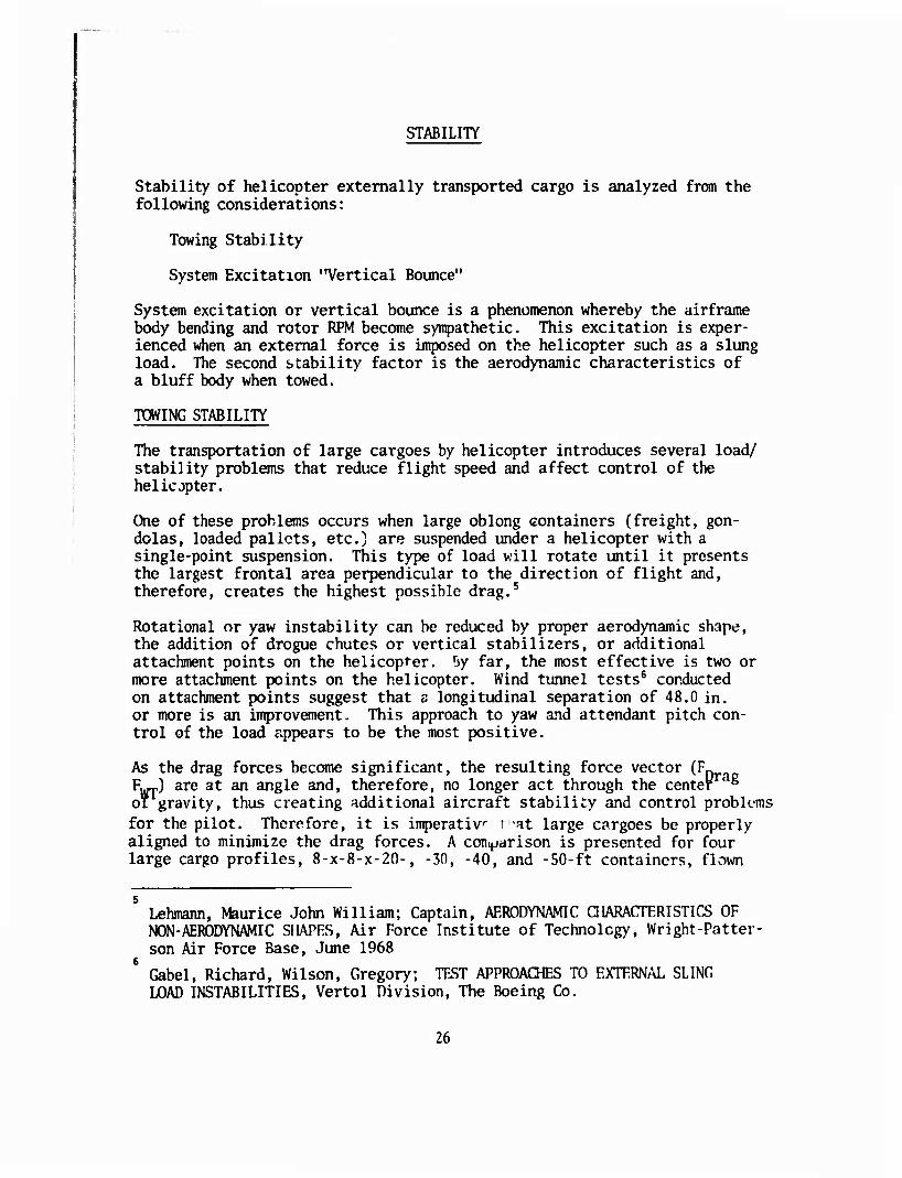
As the drag forces become significant, the resulting force vector (?«___ R^J are at an angle and, therefore, no longer act through the center * ol gravity, thus creating additional aircraft stability and control probk-ms
for the pilot. Therefore, it is imperativ t -at large cargoes be properly aligned to minimize the drag forces. A comparison is presented for four large cargo profiles, 8-x-8-x-20-, -30, -40, and -50-ft containers, flown
Lehmann, Maurice John William; Captain, AERODYNAMIC CHARACTERISTICS OF NON-AERODYNAMIC SHAPES, Air Force Institute of Technology, Wright-Patter- son Air Force Base, June 1968
Gabel, Richard, Wilson, Gregory; TEST APPROACHES TO EXTERNAL SLING LOAD INSTABILITIES, Vertol Division, The Boeing Co.
26
- CSIft"- ■
a
i 3
o
00
0) rH • i-t m
I
a»
(J-.
oo
.OL * 91 - HDHOd DVMQ
27
50 60 70 80 90 100 110 120 130
AIRSPEED - KT 0 20,000 lb
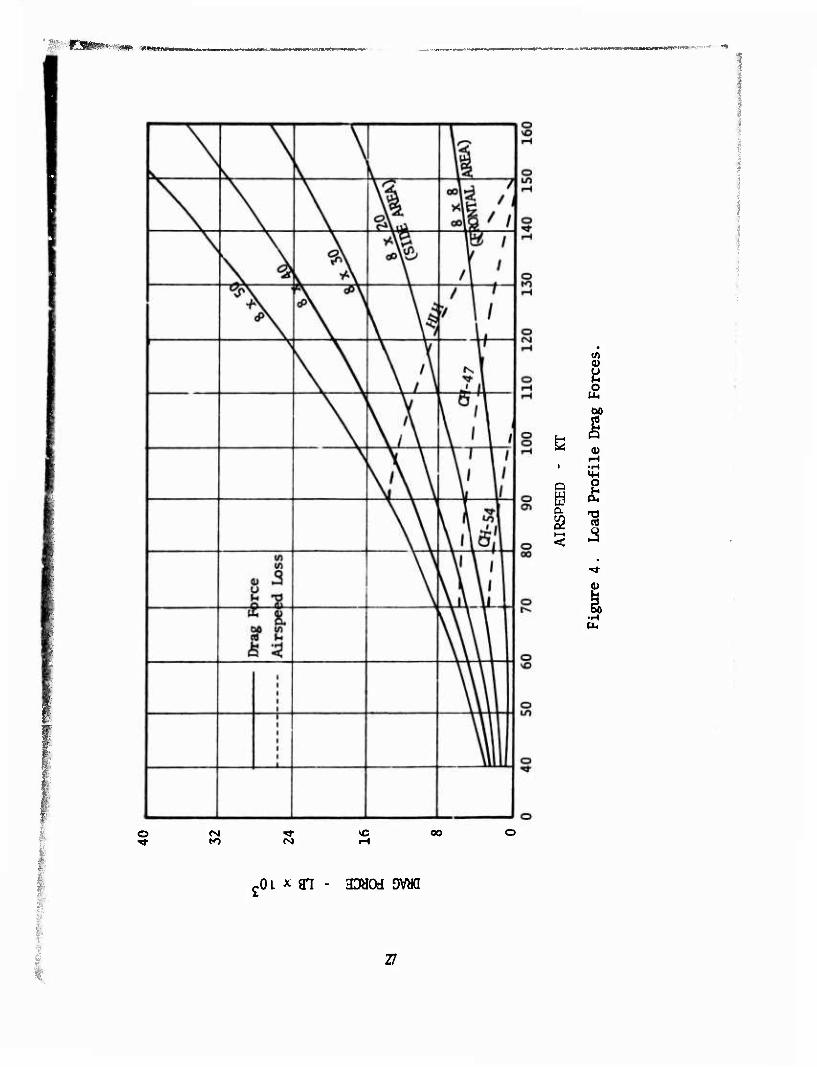
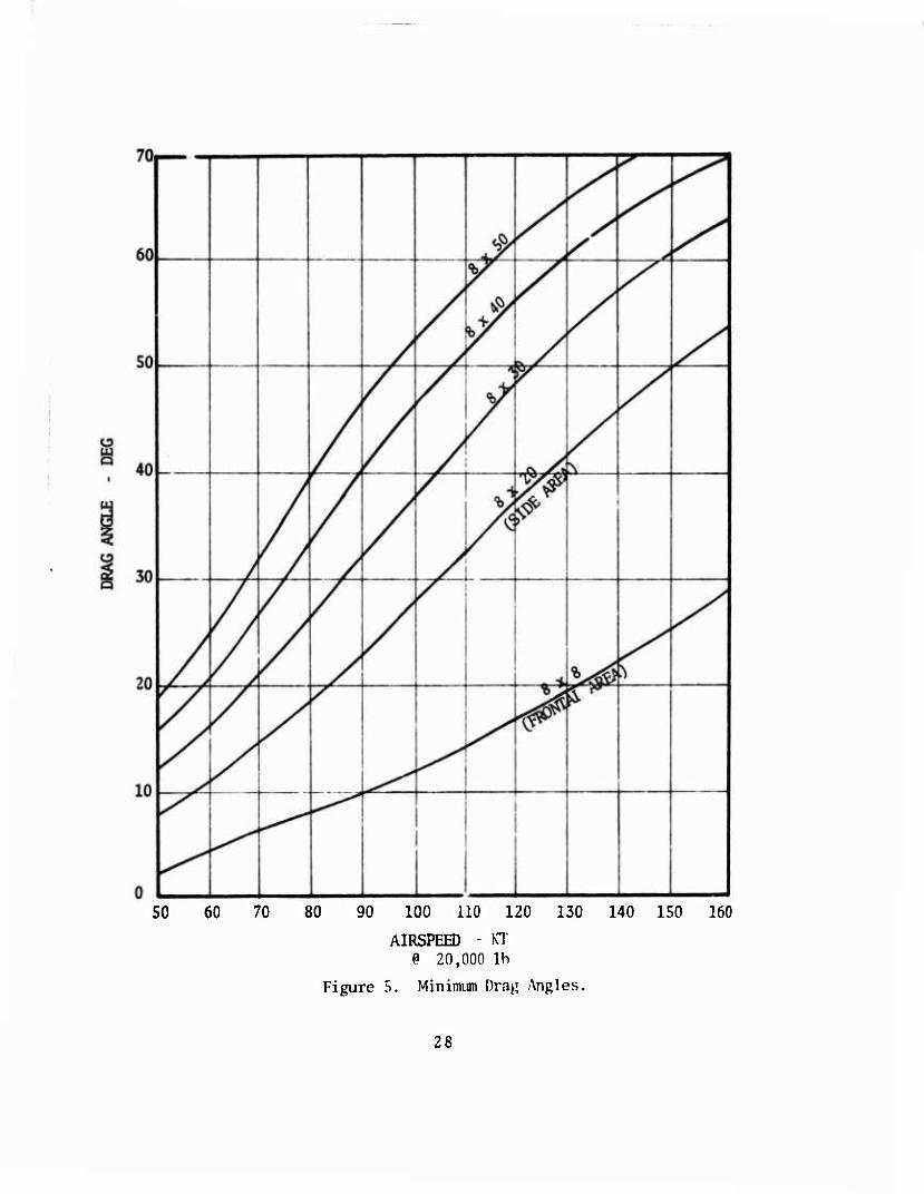
Figure 5. Minimum Drag Angles.
140 150 160
28
\ \ , \ \ \
\ \
\
\
A A A ^ A
\ 2
co\|
\ \\
\ «jr- 00 \E
Y \\
, \
\v \\
\\ \\l \\
o
o o
o
1 i $ X) |
i-i •B o c o 5
-, c u o u4 * oo ^
2 U1
5 cai
o ■ H ti,
o
o
o
o o o <N1
Daa - TiDNV jvaa
29
DHd - HTDNVDVad
30
rMHbflHMMMIP^ lÜS
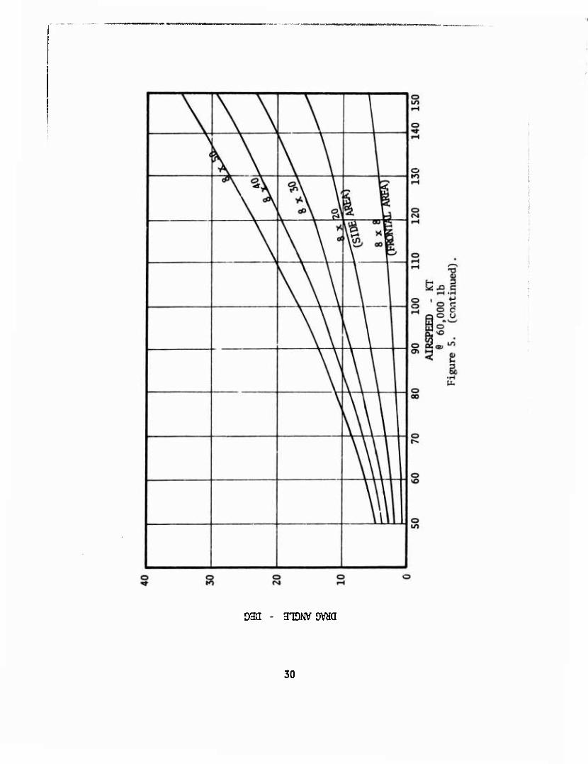
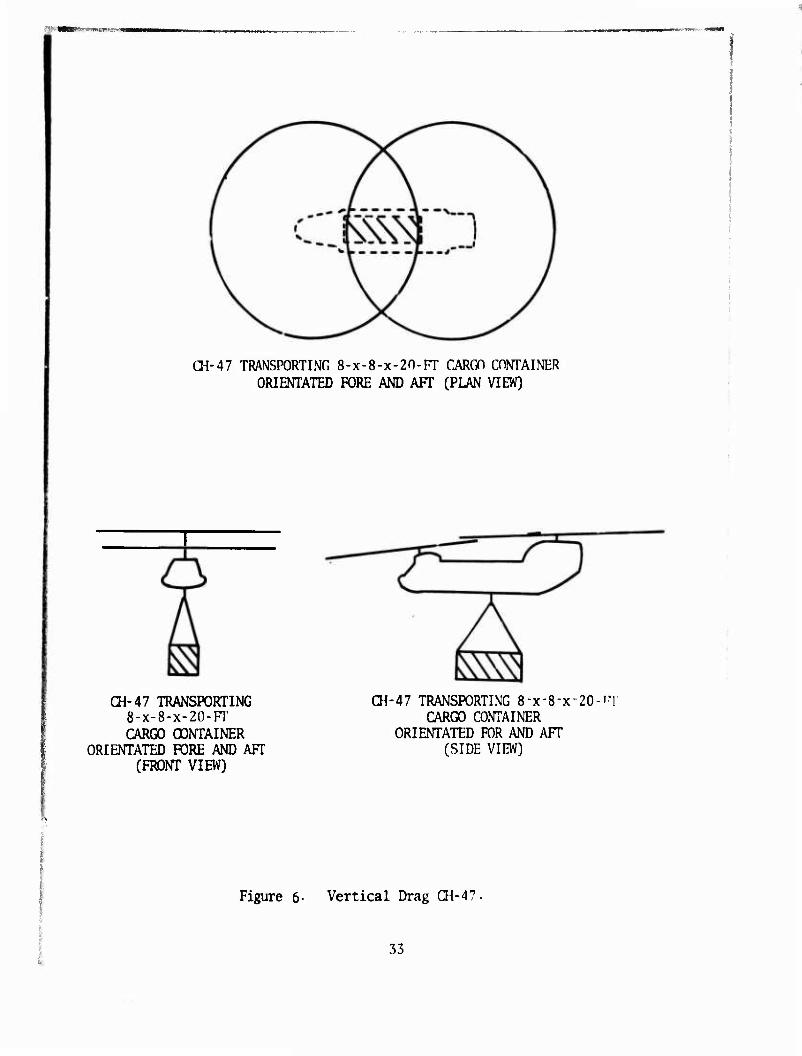
at sea level, at airspeeds from zero to 160 knots, and positioned parallel to and perpendicular to the airstream. (See Figures 4 and 5.)
FD= D^A Drag Force
Co» 1.28 Flat Plate Coefficient of Drag
A = (H) (W) or (H) (L) Flat Plate Area Perpendicular to Airstream
q = 1/2 p V2 Dynamic Pressure
p = .00237 slugs/ft2 Density of Air
It is shown that an unrestrained 8-x-8-x-20-ft load will produce drag loads of 2.5 times those drag loads which would result from a restrained load. The increased load is 6.25 for an 8-x-8-x-50-ft load.
The cargo drag angle is a function of the profile drag force and the load weight,
-1 FD ( 0 = tan i ^ )
The angle approaches 90° as the weight of the container approaches zero. The minimum possible drag angle for helicopter maximum payload is shown; at nominal airspeeds, these angles become large and will necessitate the utilization of longer than desired pendants to prevent helicopter-cargo impacts. Long pendants create additional vertical control stability prob- lems. Therefore, the advantages of rotational cargo restraint are obviously desirable (side load angles were included foi the CH-54 and HIJH even though these helicopters employ a two point or four-point hoist system which partly restrains rotation).
Vertical Drag
A second load/stability problem is the "downwash" loading on large "plan- form" cargoes. This additive loading on the cargo profile requires that some of the total helicopter lift capacity be used to counteract this load, thus reducing the useful helicopter lift capacity. The helicopter can reach a large enough forward velocity (when the cargo drag angle is suffi- ciently increased to swing the cargo out of the "downwash" airstream) to eliminate this additional load, but this does not help much since the loading is always present at the load acquisition and load release times.
Experimental "downwash" measurements were obtained by a joint US and UK test effort at Boscombe Downe, England, in May/June 1971.7 These tests were with a large "planform" cargo (12-x-52-ft bridge). The results indicate that "downwash" loading can be predicted by.
'Bradley, J., Toms, G., BRIDGE EMPLACEMENT TRIALS - PHASE II USING CH-47A AND ai-54A HELICOPTERS; Aeroplane and Armament Experimental Establishment, Boscombe Down, United Kingdom.
31
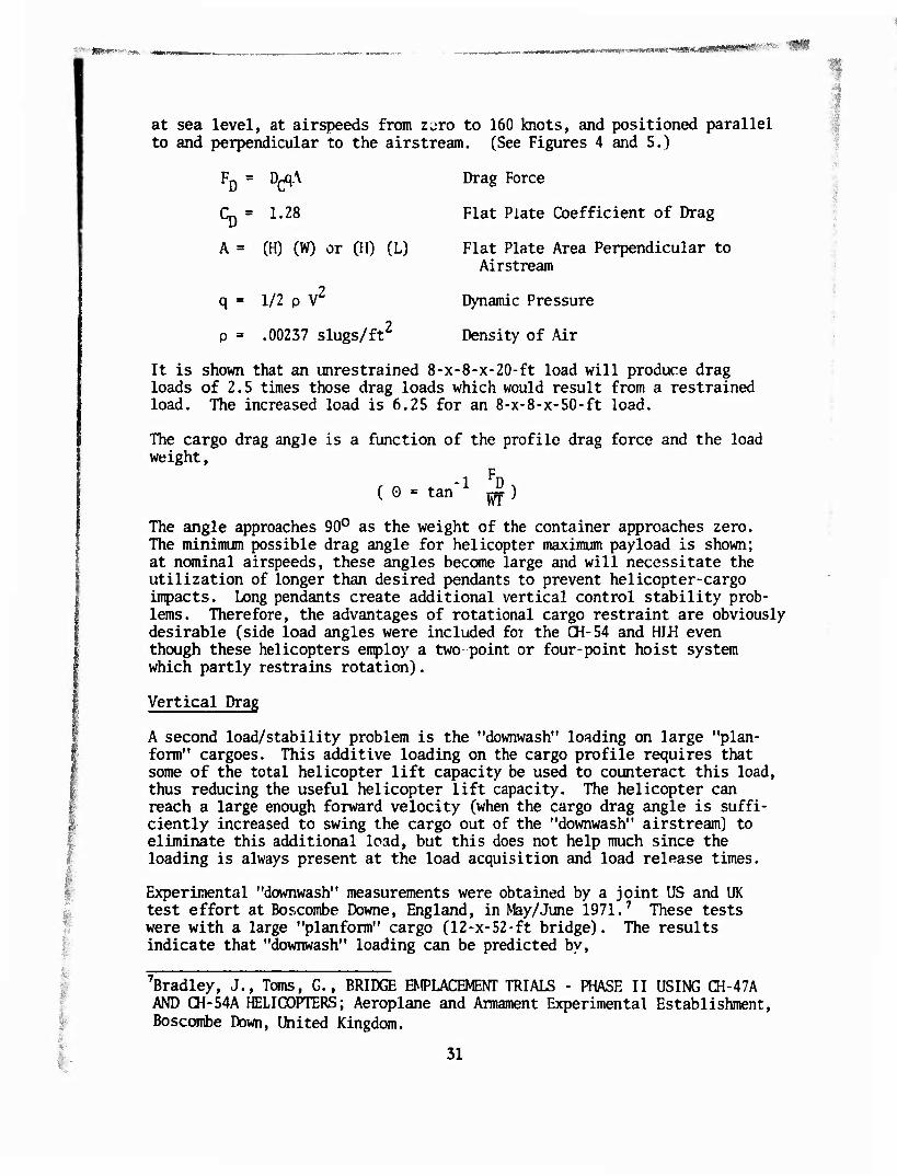
F = PD (1 - .0006 (HQi + HHC)2} (^ - ^ )
HJJ, is a fixed distance for each helicopter.
Hup has a minimum value for each size cargo, for each helicopter, in order to maintain the 30-degree maximum load angle required for most helicopters.
CH-47
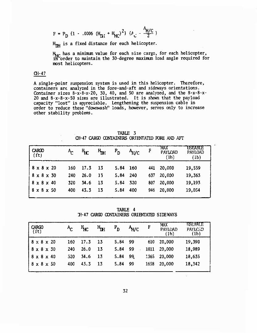
A single-point suspension system is used in this helicopter. Therefore, containers are analyzed in the fore-and-aft and sideways orientations. Container sizes 8-x-8-x-20, 30, 40, and 50 are analyzed, and the 8-x-8-x- 20 and 8-x-8-x-50 sizes are illustrated. It is shown that the payload capacity "lost" is appreciable. Lengthening the suspension cable in order to reduce these "downwash" loads, however, serves only to increase other stability problems.
TABLE 3 CH-47 CARGO CONTAINERS ORIENTATED FORE AND AFT
1 CARGO (ft) \: "HC "DH PD Vc F
MAX PAYLOAD
(lb)
U5EABLE 1 PAYLOAD i
(lb)
8 x 8 x 20 160 17.3 13 5.84 160 441 20,000 19,559
8 x 8 x 30 240 26.0 13 5.84 240 637 20,000 19,363
[ 8 x 8 x 40 320 34.6 13 5.84 320 807 20,000 19,193
8 x 8 x 50 400 43.3 13 5.84 400 946 20,000 19,054
TABLE 4 11-47 CARGO CONTAINERS ORIENTATED SIDEWAYS
CARGO (ft)
AC "HC "DH PD Vc F MAX PAYLOAD
(lb)
USEABLE 1 PAYLOAD
(lb)
i 8 x 8 x 20 160 17.3 13 5.84 99 610 20,000 19,390 1
8 x 8 x 30 240 26.0 13 5.84 99 1011 20,000 18,989 |
8 x 8 x 40 320 34.6 13 5.84 99, 1365 20,000 18,635 j
[ 8 x 8 x 50 400 43.3 13 5.84 99 1658 20,000 18,342 j
32
CH-47 TRANSPORTING 8-x-8-x-2n-FT CARGO CONTAINER ORIENTATED FORE AND AFT (PLAN VIEW)
CH-47 TRANSPORTING 8-X-8-X-20-FT CARGO CONTAINER
ORIENTATED FORE AND AFT (FRONT VIEW)
CH-47 TRANSPORTING 8-X-8-X-20 CARGO CONTAINER
ORIENTATED FOR AND AFT (SIDE VIEW)
Figure 6- Vertical Drag CH-4'
33
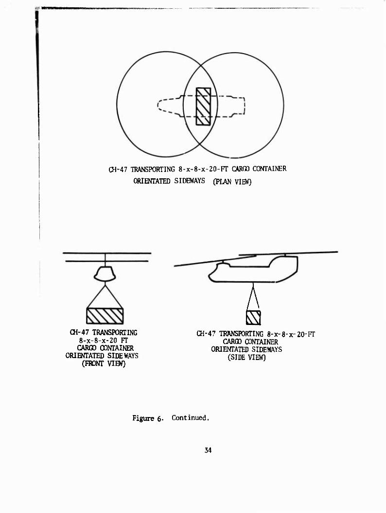
CH-47 TRANSPORTING 8-X-8-X-20-FT CARGO CONTAINER
ORIENTATED SIDEWAYS (PLAN VIEW)
(H-47 TRANSPORTING 8-X-8-X-20 FT CARGO CONTAINER
ORIENTATED SIDEWAYS (FRONT VIEW)
CH-47 TRANSPORTING 8-X-8-X-20-FT CARGO CONTAINER
ORIENTATED SIDEWAYS (SIDE VIEW)
Figure 6' Continued.
34
■wmmm^mmm MMV
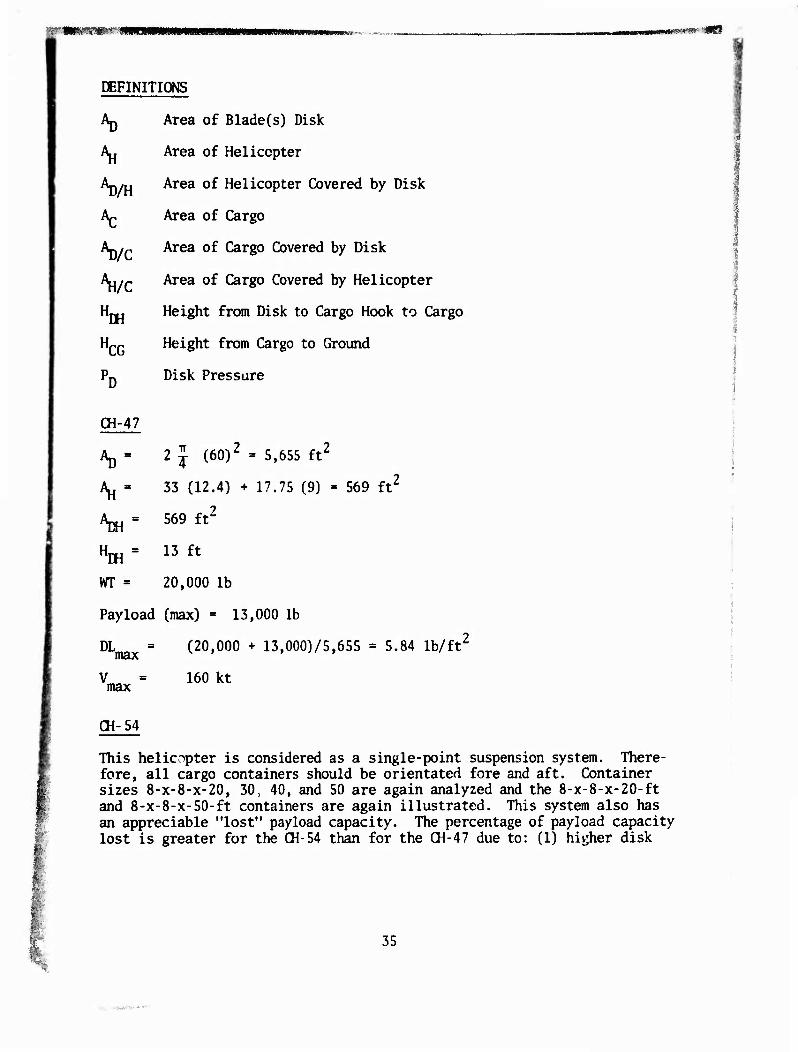
DEFINITIONS
VH
AC
Vc Vc H 'EH H CG
01-47
Area of Blade(s) Disk
Area of Helicopter
Area of Helicopter Covered by Disk
Area of Cargo
Area of Cargo Covered by Disk
Area of Cargo Covered by Helicopter
Height from Disk to Cargo Hook to Cargo
Height from Cargo to Ground
Disk Pressure
v 2 J (60)2 = 5,655 ft2
'S.' 33 (12.4) + 17.75 (9) = 569 ft2
*m- 569 ft2
"m = 13 ft
wr ■= 20,000 lb
Payload (max) • 13,000 lb
DW (20,000 + 13,000)/5,655 = 5.84 lb/ft
V max
160 kt
CH-54
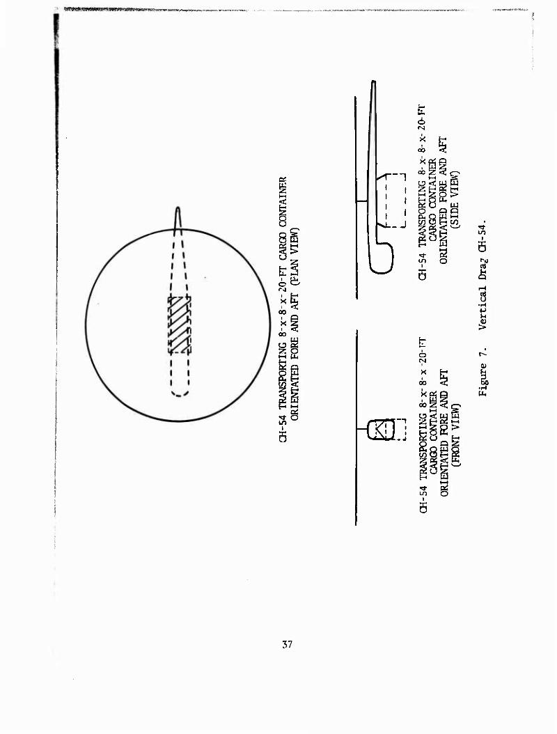
This helicopter is considered as a single-point suspension system. There- fore, all cargo containers should be orientated fore and aft. Container sizes 8-X-8-X-20, 30, 40, and 50 are again analyzed and the 8-x-8-x-20-ft and 8-x-8-x-50-ft containers are again illustrated. This system also has an appreciable "lost" payload capacity. The percentage of payload capacity lost is greater for the CH-54 than for the CH-47 due to: (1) higher disk
35
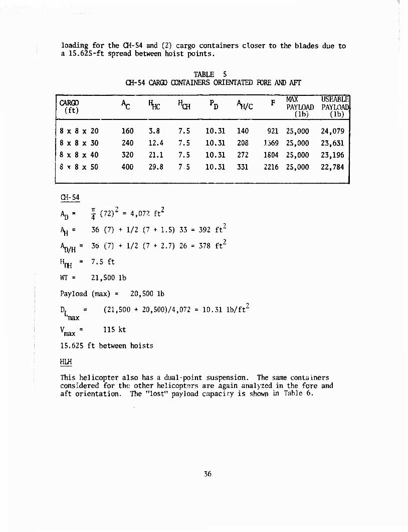
loading for the CH-54 and (2) cargo containers closer to the blades due to a 15.625-ft spread between hoist points.
TABLE 5 CH-54 CARGO CONTAINERS ORIEOTATED PORE AND AFT
CARGO (ft)
^ "HC "CH PD ^Wc F MAX PAYLOAD
(lb)
USEABLE PAYLOAD
(lb)
8 x 8 x 20 160 3.8 7.5 10. 31 140 921 25,000 24,079
8 x 8 x 30 240 12.4 7.5 10, 31 208 1369 25,000 23,631
8 x 8 x 40 320 21.1 7.5 10. 31 272 1804 25,000 23,196
8 x 8 x 50 400 29.8 7.5 10. 31 331 2216 25,000 22,784
(H-54
AD = j (72)2 = 4,07^! ft2
AH = 36 (7) + 1/2 (7 + 1.5) 33 = 392 ft'
Ap/H = 36 (7) + 1/2 (7+2.7) 26
H^ = 7.5 ft
WT = 21,500 lb
Payload (max) = 20,500 lb
378 ft'
DT max
(21,500 + 20,500)/4,072 = 10.31 lb/ft'
115 kt max
15.625 ft between hoists
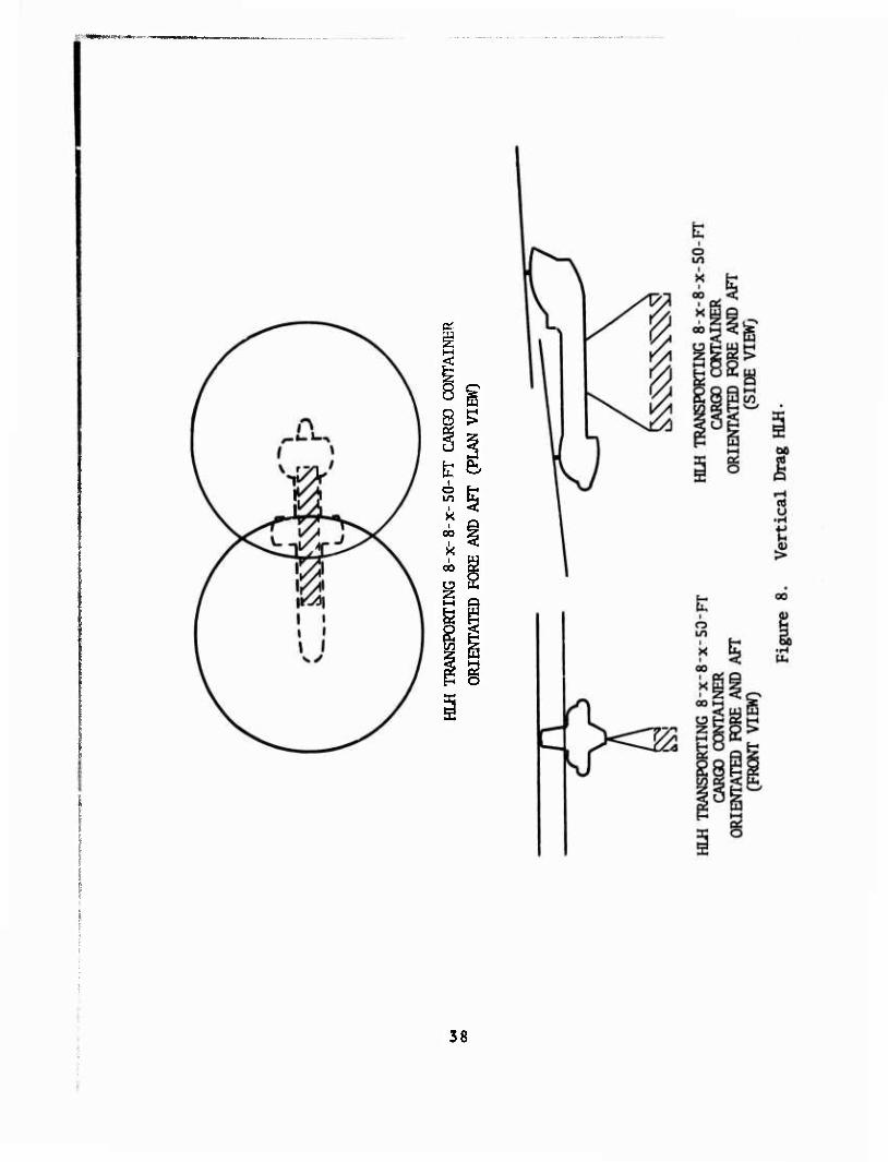
HLH
This helicopter also has a dual-point suspension. The same containers considered for the other helicopters are again analyzed in the fore and aft orientation. The "lost" payload capacity is shown in Table 6.
36
SS-'S-T^^-cp^w^^fjpitrswB^B^tw^,.™»,^
8 8S
o &
oo
S I
t o in
I I
I I
Ü J
-{Si:
6 rg
i X I
00
i 00 :io C3 •< tU W
t-i g O > H O Hi
O P Q t/) Q H ^
F § to o
^1- i
5
s • H
(U I
37
8 8. £
00 Z
oo g o
g
g
38
r,v»<>>. - -v ■ ■-■■■
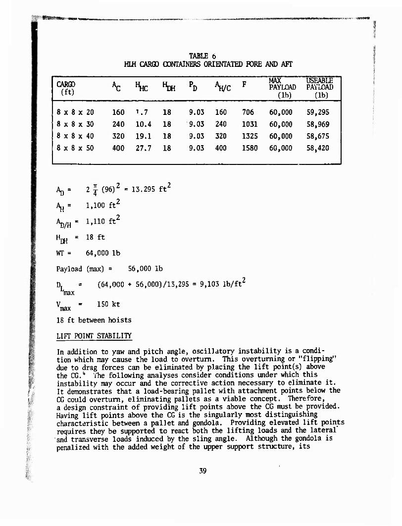
TABLE 6 HIH CARGO OCMAINERS ORIENTATED FORE AND AFT
CARGO | (ft) AC "HC »DH PD Vc F MAX
PAYLQAD (lb)
USEABLE 1 PAYLOAD
(lb) 1
8 x 8 x 20 160 1.7 18 9.03 160 706 60,000 59,295
8 x 8 x 30 240 10.4 18 9.03 240 1031 60,000 58,969
8 x 8 x 40 320 19.1 18 9.03 320 1325 60,000 58,675
8 x 8 x 50 400 27.7 18 9.03 400 1580 60,000 58,420
Ap = 2 J (96)2 = 13.295 ft2
AH = 1,100 ft2
Ap^ = 1,110 ft2
Hj^ = 18 ft
m = 64,000 lb
Payload (max) = 56,000 lb
Sna> (64,000 + 56,000)/13,295 = 9,103 lb/ft'
150 kt max
18 ft between hoists
LIFT POINT STABILITY
In addition to yaw and pitch angle, oscillatory instability is a condi- tion which may cause the load to overturn. This overturning or "flipping" due to drag forces can be eliminated by placing the lift point(s) above the CG.', The following analyses consider conditions under which this instability may occur and the corrective action necessary to eliminate it. It demonstrates that a load-bearing pallet with attachment points below the CG could overturn, eliminating pallets as a viable concept. Therefore, a design constraint of providing lift points above the CG must be provided. Having lift points above the CG is the singularly most distinguishing characteristic between a pallet and gondola. Providing elevated lift points requires they be supported to react both the lifting loads and the lateral' and transverse loads induced by the sling angle. Although the gondola is penalized with the added weight of the upper support structure, its
39
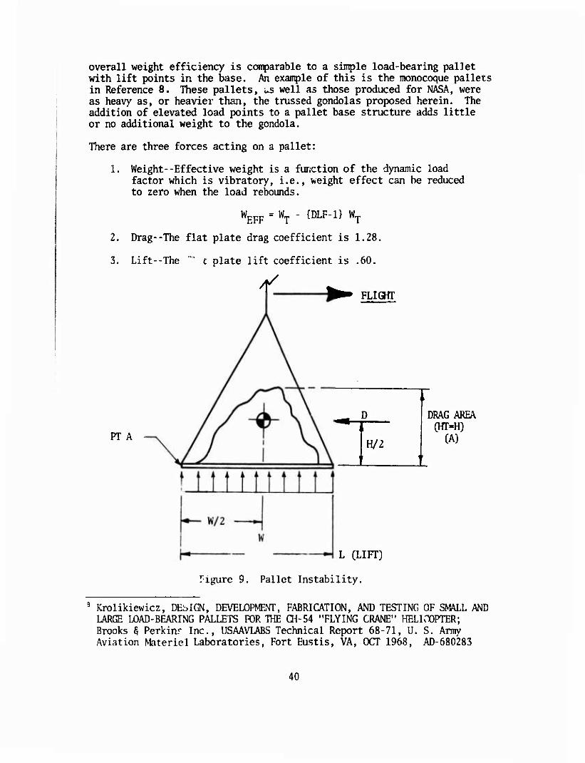
overall weight efficiency is comparable to a simple load-bearing pallet with lift points in the base. Pen example of this is the monocoque pallets in Reference 8. These pallets, us well as those produced for NASA, were as heavy as, or heavier than, the trussed gondolas proposed herein. The addition of elevated load points to a pallet base structure adds little or no additional weight to the gondola.
There are three forces acting on a pallet:
1. Weight--Effective weight is a function of the dynamic load factor which is vibratory, i.e., weight effect can be reduced to zero when the load rebounds.
W, EFF WT - {DLF-1} WT
2. Drag--The flat plate drag coefficient is 1.28,
3. Lift--The "" c plate lift coefficient is .60.
PT A
FLIGHT
D
H/2
DRAG AREA (HT-H)
(A)
L (LIFT)
•igure 9. Pallet Instability.
Krolikiewicz, DEbIGN, DEVELOPMENT, FABRICATION, AND TESTING OF SMALL AND LARGE LOAD-BEARING PALLETS FOR THE 01-54 "FLYING CRANE" HELirOPTER; Brooks 5 Perkinr Inc., USAAVLABS Technical Report 68-71, U. S. Army Aviation Materiel Laboratories, Fort Eustis, VA, OCT 1968, AD-680283
40
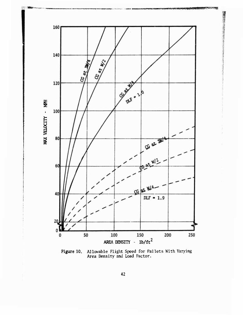
10.
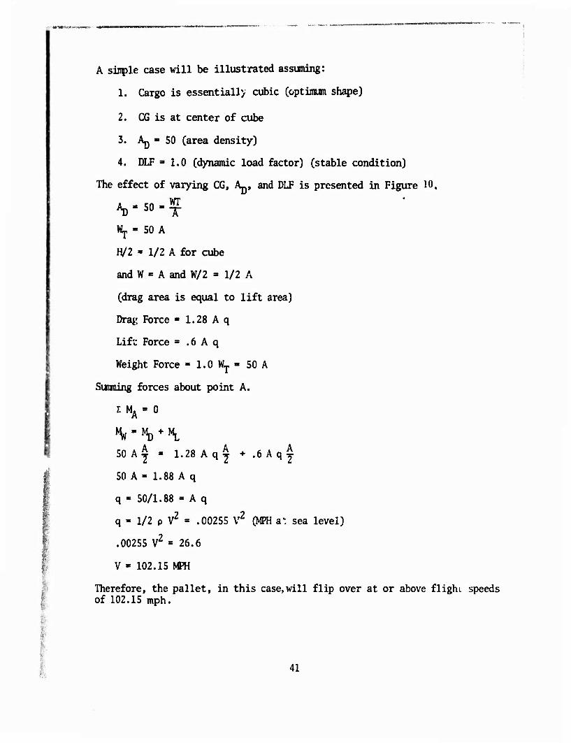
A simple case will be illustrated assuming:
1. Cargo is essentially cubic Coptiraura shape)
2. CG is at center of cube
3. AQ = 50 (area density)
4. DLF =1.0 (dynamic load factor) (stable condition)
The effect of varying CG, A-., and DLF is presented in Figure
AD-50'? WJ. « 50 A
H/2 - 1/2 A for cube
and W - A and W/2 = 1/2 A
(drag area is equal to lift area)
Drag Force ■ 1.28 A q
Lift Force = .6 A q
Weight Force - 1.0 WT » 50 A
Sunning forces about point A.
E MA » 0
50 A^ » 1.28 Aqy + .6 kq^
50 A - 1.88 A q
q « 50/1.88 - A q
q - 1/2 p V2 « .00255 V2 (MPH a", sea level)
.00255 V2 = 26.6
V - 102.15 MPH
Therefore, the pallet, in this case,will flip over at or above flight speeds of 102.15 mph.
41
_ Mmaamm^alf^mf^^^^
AREA DENSITY - lb/ft
Figure 10. Allowable Flight Speed for Pallets With Varying Area Density and Load Factor.
42
160
140
120
I 100
80
60
40
20
/ /
• /
" 1 L/
* /
7 kH / A A [^
//
* \
/ 1
\ A 7
<$$J. i 1 i l
A ^ DLF > 2. o 1
kill/ 0 5 0 10 0 IS 0 20 0 250
AREA DENSITY - lb/ft
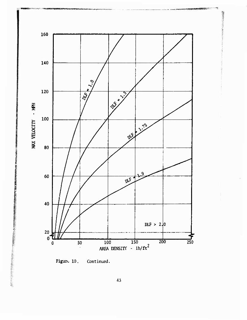
Figure 10. Continued.
43
It is seen that the permissible flight speed can be increased to a max- imm by reducing the overturning moments produced by the variable forces of lift and drag. The drag moment can be reduced to zero if the pallet attachment points are raised (through the addition of stanchions at the four comers) to the height level of the center of the drag area. Then the moment equation becomes
50 A £ = .6 a q ^
50 = .6 q
q = 8?i.333
83.333 = 1/2 p V2 = .00255V2 (MPH at sea level)
V = 180.78 MPH max
If the attachment points are raised again, then the pallet (which became a gondola with the addition of stanchions) will tend to rotate about the forward attachment points (instead of the rear attachment points) and the drag again contributes to the overturning moment; therefore, the per- missible flight speed will be reduced accordingly.'
VERTICAL BOUNCE
Vertical bounce was investigated to determine what effect, if any, the gondola structure might introduce. The vertical bounce phenomenon occurs when an outside force such as a slung load is introduced to the system (helicopter). If the slung load suspension system and the helicopter have a coupled frequency less than the helicopter natural frequency, significant aircraft vibrations will be experienced. The recommended procedures to determine this coupled frequency are presented in Reference 4. The para- meter which can be selectively controlled in avoiding a nontrivial fre- quency is the spring constant of the sling system. The spring constant of the gondola is several orders of magnitude greater than any of the spring constants of the sling system. Therefore, the spring constant of the gondola should have no effect on the system coupled frequency.
MATERIALS AND METHOD OF CONSTRUCTION
The choice of materials and rnethods of construction must satisfy the following parameters,
44
Structural Integrity
Environmental Resistance
Minimal Cost
Attendant factors weight, strength, availability, and cost must be inher- ent in the choice of material and the method(s) of construction.
Methods of Construction
Aside from the basic material properties are those characteristics which provide ease of fabrication (machinability, formability, and joinability). These factors influence both structural application and fabrication costs. Principally, the gondola requirements are light weight, ruggedness, and porous structure. The criterion for light weight suggests the use of a material that has a high strength-to-weight ratio and should be available in structural shapes which are efficient in reacting the principal load conditions. Since the pal let/gondola is acquired at load points which are at or above the load CG, the floor is subject to bending and shear loads which are in turn transferred to the lift attachment points. The relatively high load encountered locally requires significant shear and bearing properties of the materials. To satisfy the floor bending and shear loads, it is suggested that beam members or a monocoque structure of skin and stringers or honeycomb sandwich which may be joined by welding, brazing, adhesive bonding, or riveting be used. The transfer of local loads requires local reinforcements which distribute the load transfer over a fairly large area of the relatively weak skin of the monocoque structure. In addition, the monocoque structure is difficult to repair without special tools and in some instances facilities. The use of sheet stock for the monocoque structure makes it highly vulnerable to impact damage and related degrading effects from corrosion and abrasion. The loss of a few mils of material of thin-gauge sheet stock becomes a significant percentage of the working material. In summary, the damage threshold and the load transfer detract significantly from the weight saving that might be expected from monocoque structures. Additionally, the monocoque floor system requires significant reinforcement for axle bearing loads and local loads due to tie-downs.
Field experience from bonded sandwich structures utilized in pallet con- struction reveals a high vulnerability to compression failure in the sand- wich core material and delaminations. It appears that the potent* il for this type of construction is low-cost retirement life-cycle appli. cions. Since the gondola requires elevated lift points for stability, the nport structure of these points must be integrated into the overall structure to support the bending moments due to floor loads. Structural efficiency would dictate that the side support structure be utilized as a truss. For convenience of fabrication and economy, the principal structural framing members can be comprised of axial load members. The side truss members can be pinned for field removability, affording access for loading or for stowing compactly. The floor system joining the principal side
45
truss frame is composed of crossbeams which support a porous grating over- lay. This floor when compared to a monocoque system demonstrates comparable weight savings with the added features of impact and corrosion resistance, cargo tie-down provisions, and field replaceability. The use of rugged structural shapes allows the designer the option to use mechanical fast- eners or to weld the members without supplemental doublers or machined fittings. The material should have properties compatible with this method of joining, which requires good shear and bearing variability; these characteristics are not embodied by the anisotropic materials such as fiber reinforced plastic (FRP] and wood. These materials demonstrate good structural properties when utilized in composite monocoque structure or when compound curvature is a premium design consideration.
Structures which may be analogous to the gondola in their operational interfaces are containers and load-bearing pallets. Containers are con- structed of various materials including the conrnon steels, aluminum, fiber reinforced plastic, and wood. Pallets utilize approximately the same materials, with wood as the predominate material. The fact that containers are a complete enclosure, sheet-stringer or composite structures of wood and fiber reinforced plastic are frequently employed. The container structure, because of its closed feature, utilizes sheet stock in the sides, ends, and top. Experience has shown this feature to be highly susceptible to impact damage, corrosion, and cracking around fastener penetrations.
The desirability of rugged and porous gondola structures permits the designer to efficiently support the load by a trussed side and end struc- ture that has relatively thick walled members. The containers generally utilize rugged structural shapes for floor side beams and transverse cross members. Although the container floor design capacity (lb/ft2) is higher, it does not experience the dynamic load factors encountered in externally slung helicopter transport. Additionally, the roof and upper siderail members are inadequate for top comer lifting. Although some of the structural requirements are analogous to the container, the elevated lift points with attendant angular sling loads required a substantial increase in member sizing, particularly the upper siderail member and its secondary truss members.
Several significant material and construction disadvantages are apparenet from a review of container pallet designs which should be avoided. This evaluation suggests the use of rugged structural members of a material which has high strength-to-weight ratios, is corrosion resistant, and demonstrates good shear and bearing properties.
Materials
Selection of materials to construct pallets/gondolas presents a dilemma when one considers the myriad options which include composites and their fibers and orientation. Evaluation of candidate materials for this appli- cation will of necessity be limited to the following salient characteristics:
46
—ww—
Strength-to-weight ratios to minimize tare weight.
Price-to-strength ratios to minimize cost.
Corrosion resistance to minimize in-service degradation.
Mechanical properties other than strength which would affect serviceability.
Availability of shapes and degrees of processing to achieve the end product.
There is no single figure of merit which can be assigned to each of the materials. However, several comparisons can be presented which reflect trends and limit the candidates to a degree.
Strength-to-Weight-Ratios
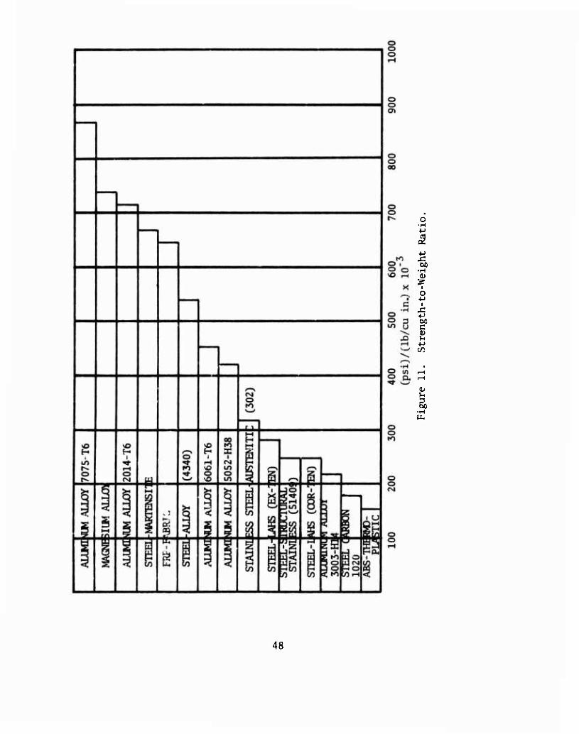
Since the pallet/gondola will be transported by helicopter and quite pos- sibly by fixed-wing aircraft, it is imperative that the tare weight be kept at a minimum. The relatively high operating costs of these transportation modes must be utilized carrying cargo rather than tare weight. Several candidate materials used in the aerospace and commercial container industry are presented. Strength-to-weight ratios are presented in Figure 11. It is observed that two aluminum candidates rank the highest on the scale. Although some materials such as advanced composites and certain other metals would rank higher, they are not considered for obvious cost and utility. These two alloys are widely used in aerospace structures, but due to their susceptibility to corrosion, they are not used in the maritime industry. However, the next aluminum candidate ranks above average on this scale and possesses other desirable properties.9
Bidirectional fiber reinforced plastic materials demonstrate good potential behind the aluminum alloys. It would be possible to select a fiber rein- forced plastic with a highly unidirectional characteristic to its reinforc- ing fabric and show fiber reinforced plastic to be superior to aluminum.10
however, with a reasonable balanced fabric and resin matrix, fiber rein- forced plastic ranks more favorably than aluminum alloy 6061-T6. Figure 11 shows, however, that even a bidirectional fabric such as 181, which loses approximately KK of its strength in the transverse direction, loses approximately 501 of its strength in the 45° direction. In general, the fiber reinforced plastic when used in sandwich structures compares favor- ably with aluminum. The advantages of fiber reinforced plastic are best exploited when load paths are predictable to take advantage of the direc- tional properties of the material. However, the relatively low bearing and shear strength of fiber reinforced plastic imposes restraints that Isotropie materials do not.
9 Military Handbook Strength of Metal Aircraft Elements, Department of Defense, MIL-HDBK-5, 1 September 1971
10 Military Handbook Plastics for Aerospace Vehicles, Department of De- fense, MIL-HDBK-17A, January 1971
47
o •H
bo •H
0.
■ H
48
Steels range widely on this scale from the high ranking of martensitic steels to the low ranking of the carbon steels. The corrosion-resistant steels do not demonstrate an advantage over corrosion-resistant aluminum.
Strength-to-weight difference, while not a conclusive indicator for selec- tion of material, does provide an indicator to the designer. However, this factor alone would be misleading when one selects a high-ranking steel which allows thin sections but which would be severely degraded by cor- rosion and vulnerable to impact. On the other hand, a low-ranking mater- ial when used in composite construction becomes efficient.
Cost/Strength Ratio
The consideration of a cost parameter in material performance comparisons is essential, since the application of engineering materials invariably includes economy as a decision factor.
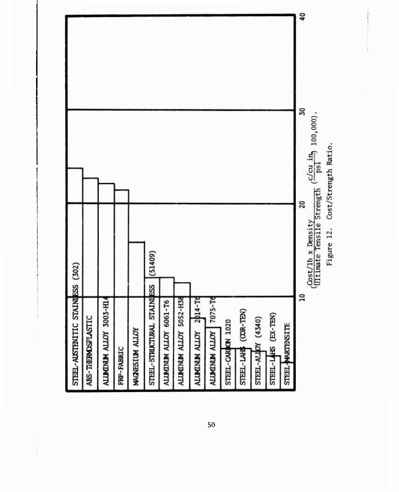
The advantage of steel is inmediately obvious. Most of the low-ranking (favorable) positions are occupied by steel. The higher strength steels are in the most favorable positions, showing that, in general, costs do not rise in proportion to the gain in strength. It is also apparent that no cost penalty must be paid for the improved corrosion resistance of COR-TEN. However, the fully stainless group of steels is not in this favorable position. (See Figure 12.)
Aluminum alloys are in the mid-range positions. There is a sharp increase from steels to aluminums. Then the aluminum alloys increase from the stronger alloys upward, similar to the behavior noted for the steels. Thus, economy considerations would lead to selection of the higher strength alloys. Tins is particularly true when the corrosion-resistant steels are compared to aluminum 6061-T6.
It should be noted that aluminum showed a more favorable position in Figure 11 than its ranking in Figure 12. Similarly, fiber reinforced plastic shows a similar reversal. It appears that the higher strength alloys of steel and aluminum show a favorable trend in cost-to-strength compari sons.
Composite Rating
Composite rating of the materials is difficult; however, the alloys of aluminum and steel demonstrate the most favorable position overall. The most frequently used alloys of aluminum in structural applications (50S2- H38 for sheet and 6061-T6 for extrusions) are medium in their ranking with respect to the other alloys. Their corrosion resistance rating is excel lent in industrial atmospheres and good to very good in marine atmospherei-. Their availability in both sheet and structural shapes permits flexibility for the designer.
49
50
'Hp*«^»^iS*?»«piW«»Ä»!^^ ra—w——aw—n— ■ i .II --■n-if-fW^a«^1
Aluminum alloy 7075-T6 demonstrates an overall advantage over the more common 5052 and 6061 alloys. However, its poor weldability and less re- sistance to corrosion detract from its composite rating. This alloy, with proper surface treatment, should be used whenever welding can be avoided. Although aluminum rates lower overall than the alloy steel, its superior corrosion resistance gives it a decided overall advantage.
Fiber reinforced plastic material compares less favorably overall than do ail the alloys of steel and aluminun unless directionality of load is controlled. The advantage of fiber reinforced plastic tends to improve in composite sandwich structures when used as a face sheet. However, the desirability of rugged and porous structures tends to minimize a fav- orable application for thi:- material for gondola fabrication.
The composite rating of alloy steels would suggest that they be considered to the maximum extent. However, to take advantage of their composite rating would in many instances dictate relatively thin wall shapes, which are prone to impact damage, and high percentage thickness reduction due to corrosion and abrasion. These factors point out the pitfalls using rating indices.
A composite rating of materials based solely on strength, weight, and cost is, at best, an indication only. The final choice must be resolved for the application. The application of these materials in an efficient load-carrying pallet/gondola structure can be further analyzed by the material shape availability and resistance to environmental degradation. The basic design constraints previously mentioned which are pertinent to the structure are as follows:
Cube Capacity
Payload Capacity
Minimum Tare Weight
Elevated Lift Points
Porous Structure
Corrosion Resistance
Impact Resistance
Fatigue
The first two requirements have little or no impact on the choice of ma- terials. However, the remaining characteristics are significant to material selection.
51
Minimum tare weight is a function of strength-to-weight ratio and available shape for optimized placement. Certain materials may demonstrate favor- able strength, weight, and cost, but they are not available in an effi- cient shape. Structural requirements of porosity and ruggedness to mini- mize impact damage suggest the avoidance of thin gauge sections. There- fore, the use of structural members will be paramount and the material should be easily formed or extruded. Additionally, the material must demonstrate good joining capability. This becomes an immediate problem with plastics and fiber reinforced plastic, which must be reinforced lo- cally to distribute the load transfer over a relatively large area.
Therefore, the material should be readily joined by mechanical fasten- ing, welding, brazing, etc., which are relatively inexpensive methods com- pared to adhesive bonding at local connections. Additionally, the ma- terial must demonstrate good bearing and shear strengths consistent with efficient joints. Fatigue strength of the candidate? materials is nearly proportional to ultimate strength and will invariably follow the ranking of strength-to-weight ratios. From this material evaloation, the two candidates which offer the greatest potential are aluminum and steel. Therefore, judicious use of these materials should be considered for the framing members as a minimum. Joints and connections to minimize bulk may of necessity utilize steel and continuous members utilize aluminum.
52
SUPPORT EQUIPMENT
Support equipment for the gondola, ii. - Htion to the interface require- ment with the helicopter and other trans tation modes, will include, to the maximum extent, available materi?". md equipment organic to the transportation terminal. The gondola by _ s nature provides bearing con- tainment of the load with its floor system; however, end, side, and top containment must be supplemented in these areas by straps, nets, and dunnage fabricated in place. Available equipment and materials appear to be adequate to support the utilization of the pallet and gondola. The salient interfaces of the support equipment are as follows:
Loading
Restraining
Ground Mobility
Attachment to Helicopter
Unloading
Return
Any one, or all, of these interfaces may require some support equipment which could be identified during logistic supply trials. However, the equipment which appears to be inadequate is ground mobility support at
I both the terminal and user organization.
LOADING
The gondola can be loaded by using conventional materials handling equipment such as conveyors, hand trucks, ramps, and forklifts. The standard ^f^E could be used to load and unload break-bulk cargo.
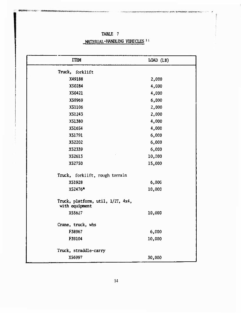
A desirable feature of the gondola would be one which permits the load to be placed from the side or ends. Invariably, all the concepts con- sidered may be loaded from the top and both ends by removing two diagonal braces. In most cases one or both sides can be removed by simply un- pinning. Where it is desired to allow a forklift to traverse the floor of the gondola, dunnage material such as plywood or planking could bridge the grated floor. Floor structure sufficient to allow a 4,000-lb forklift carrying a 2,000-lb load adds 500 lb or more to the base structure. Accessibility in placing loads on the gondola by forklift is advantageous since the gondola, unlike a container, permits loads which can extend above the top plane. A typical listing of Nfffi equip- ment from Reference 11 is shown in Table 7.
^FMlOl-lO-l, STAFF OFFICERS FIELD MANUAL, July 1971.
53
r&*iimmTKr!rri**-:*rm***-<.\; '««Ha»^wt«w-iKP*iW*iw^^- «MM "»^«mWWS?' «MIMP'W^B '
TABLE 7
MATERIAL'HANDLING VEHICLES 11
| ITEM LOAD (LB) 1
I Truck, forklift
X49188 2,000 |
X50284 4,000
X50421 4,000 |
X50969 6,000 1 X51106 2,000 1
1 X51243 2,000
X5I380 4,000
X51654 4,000 |
j X51791 6,000 j
X52202 6,000 |
j X52339 6,000
X52613 10,000 |
X52750 15,000
I Truck, forklift, rough terrain
X51928 6,000
X52476* 10,000
Truck, platform, with equipment
util. 1/2T, 4x4,
j X55627 10,000
I Crane, truck, whs
F38967 6,000
| F39104 10,000 j
I Truck, straddle-carry
X56997 30,000 |
54
yi&t&ey ^fjff'VW'MfC^»' ■
CARGO RESTRAINTS
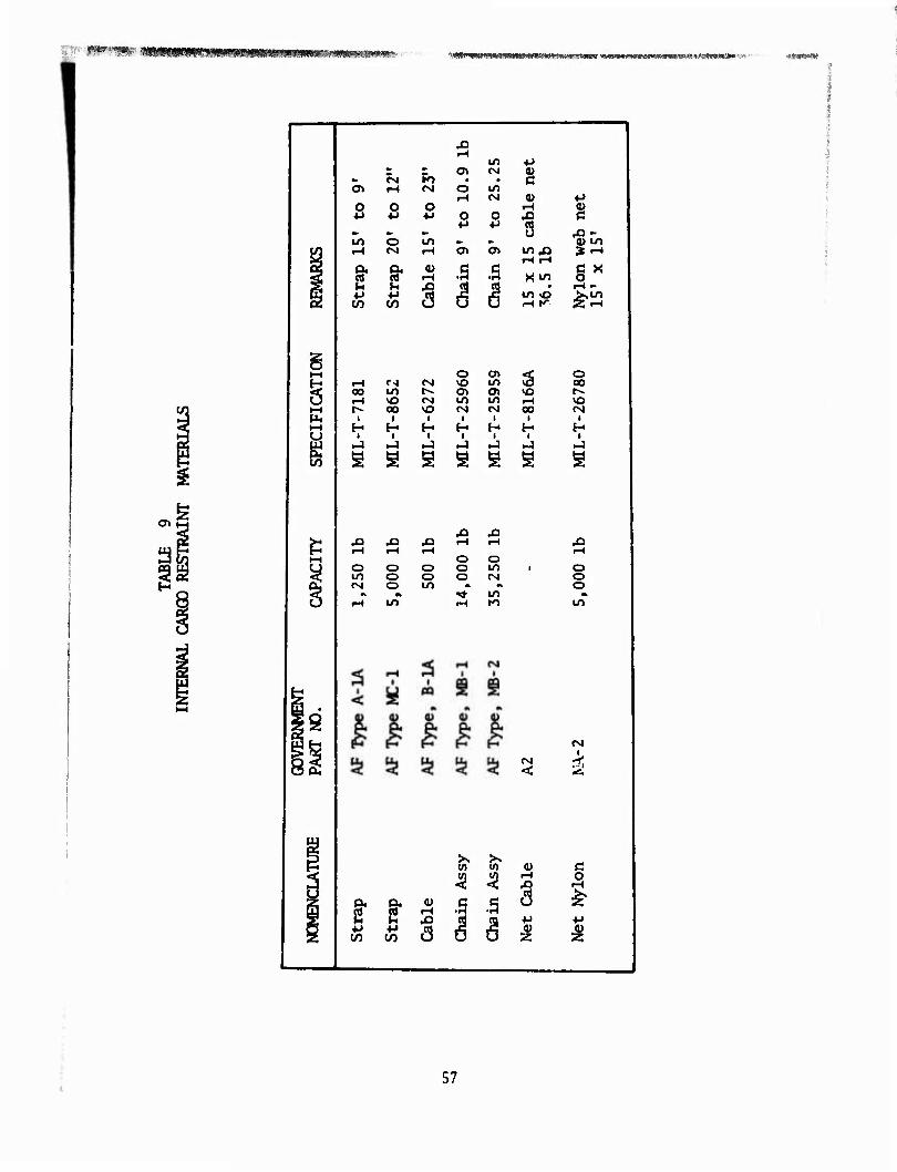
Cargo can be secured by using conventional methods such as straps, cables, and chains. Table 8 lists the available federal stock numbers of materials for securing external cargo. In addition, a listing of aircraft tie-down materials is included in Table 9. Some of the concepts have tie-down rings located in the base of the gondola similar to aircraft internal cargo provisions. In addition, the floor system is porous, permitting the riggers to pass straps, wire, rope, etc., in securing the load to the crossbeams or other base structure. Since the gondola as conceived is an open trussed structure, some supplemental containment of small items may be desirable to minimize tie-down straps. It appears that some of the available nets could be utilized in this manner. Additionally, dunnage material could be fitted to the sides and ends to facilitate the containment of loose items. In general, the gondola affords flexibility in cargo tie-down and restraint.
GROUND MOBILITY
Ground mobility of the gondola should be provided in forklift, mobilizer dollies or skids. The most direct and efficient method is by forklift. However, the available forklift capacity organic to the terminal transfer unit does not have sufficient capacity for the 20,00ü-lb capacity gondola. Unless the loading ai d unloading of the gondola is accomplished at the acquisition site, the loaded gondola could not be moved with existing forklifts. Since the gondola is designed for transport by vertical lift, it is desirable to use the lift points for surface transpolt as well. This would require a straddle carrier or a mobile crane unit. However, provisions for forklift handling should be required. Additionally, those pallet/gondola concepts having an 8-x-8-ft cross section can be transported by highway or rail. Some of the gondola concepts presented do not directly permit forklift handling; however, they would accept top-lift carriers or straddling transporters. This type of equipment is presently not available and would introduce new requirements.
HELICOPTER ATTACHMENT
Helicopter attachment is accomplished through a load acquisition device or a sling set having one or more legs. The gondola must provide a suitable attachment point to which slings may be secured. The attachment point to the load shall always be at or above the mid-height of the load. All of the gondola configurations present either single-, two-, or four-point load attachment, which permits attachment to either of the helicopters.
Single Point
The CH-47 helicopter has single-point attachment, while the QI-54 has both single- and four-point attachment. The Ql-54 is assumed to use single- point attachment since the limited length of the individual four-point reels do not lend themselves to efficient rigging and load acquisition in
55
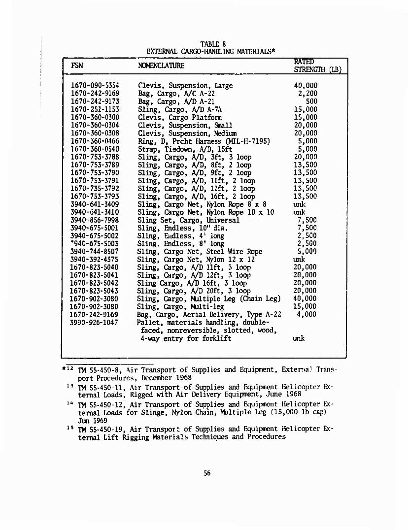
TABLE 8 EXTERNAL CARGO-HANDLING MATERIALS*
FSN NOMENCLATURE ■RST05 STRENGTH CLB)
1670-090-5354 Clevis, Suspension, Large 40,000 1670-242-9169 Bag, Cargo, A/C A-22 2,200 1670-242-9173 Bag, Cargo, A/D A-21 500 1670-251-1153 Sling, Cargo, A/D A-7A 15,000 1670-360-0300 Clevis, Cargo Platform 15,000 1670-360-0304 Clevis, Suspension, Small 20,000 1670-360-0308 Clevis, Suspension, Medium 20,000 1670-560-0466 Ring, D, Prcht Harness (MIL-H-7195) 5,000 1670-360-0540 Strap, Tiedown, A/D, 15ft 5,000 1670-753-3788 Sling, Cargo, A/D, 3ft, 3 loop 20,000 1670-753-3789 Sling, Cargo, A/D, 8ft, 2 loop 13,500 1670-753-3790 Sling, Cargo, A/D, 9ft, 2 loop 13,500 1670-753-3791 Sling, Cargo, A/D, lift, 2 loop 13,500 1670-735-3792 Sling, Cargo, A/D, 12ft, 2 loop 13,500 1670-753-3793 Sling, Cargo, A/D, 16ft, 2 loop 13,500 3940-641-3409 Sling, Cargo Net, Nylon Rope 8x8 unk 3940-641-3410 Sling, Cargo Net, Nylon Rope 10 x 10 unk 3940-856-7998 Sling Set, Cargo, Universal 7,500 3940-675-5001 Sling, Endless, 10" dia. 7,500 3940-675-5002 Sling, Endless, 4' long 2,500 '940-675-5003 Sling, Endless, 8» long 2,500 3940-744-8507 Sling, Cargo Net, Steel Wire Rope 5,000 3940-392-4375 Sling, Cargo Net, Nylon 12 x 12 unk 1670-823-5040 Sling, Cargo, A/D lift, 2> loop 20,000 1670-823-5041 Sling, Cargo, A/D 12ft, 3 loop 20,000 1670-823-5042 Sling Cargo, A/D 16ft, 3 loop 20,000 1670-823-5043 Sling, Cargo, A/D 20ft, 3 loop 20,000 1670-902-3080 Sling, Cargo, Multiple Leg (Chain Leg) 40,000 1670-902-3080 Sling, Cargo, Multi-leg 15,000 1670-242-9169 Bag, Cargo, Aerial Delivery, Type A-22 4,000 3990-926-1047 Pallet, materials handling, double-
faced, nonreversible, slotted, wood, 4-way entry for forklift unk
*12 TM 55-450-8, \ir Transport of Supplies and Equipment, Exterr.ai Trans- port Procedures, December 1968
13 TM 55-450-11, Air Transport of Supplies and Equipment Helicopter Ex- ternal Loads, Rigged with Air Delivery Equipment, June 1968
"* TM 55-450-12, Air Transport of Supplies and Equipment Helicopter Ex- ternal Loads for Slinge, Nylon Chain, Multiple Leg (15,000 lb cap) Jun 1969
15 TM 55-450-19, Air Transport of Supplies and Equipment Helicopter Ex- ternal Lift Rigging Materials Techniques and Procedures
56
::: f**'**** 'mmmimT^mi>m^^^mmmmsmmmi^»-' "-WtMIWIlHIMUHI Hill ■ I l.'.H"TO«i!» ^MIHIII ■WimulMMUWffifcWI' «■
o>
t-H o en < o H •H f-) (M VO in VÖ oo 6 oo 10 1-- Ol CT> o t^.
r-l vO <M U1 u> r-t \o t^ 00 NO CM (VJ oo tM
H E- H H E- H H J J »J <-) J ►J »J s s s s s s s
1—I
CM O» «-4
O
U1
W
<M
O O 4-* 4-)
CM r-(
O
O
in (M
in (M
O 4J
o> at
8* 9- ^ II 3 I I
a> t-t
in .a
in o .-H K
8* f -S I •§ S t -s J 5 CO to u U u
r-t
4-)
o iH - >,in
o o o O o o Ln i o in o o o (NJ o rsi o in * M o A M »* in *
tH tn tH to in
<M I
-r
c o
57
hover. The single-point suspension presents problems of in-flight sta- bility which limits flight speeds well below normal. The principal cause of this instability is the flying of bluff bodies broadside to the airstream. Two deleterious effects are encjuntered from this lack of yaw control: the drag forces reduce speed and the trail angle becomes sufficiently large to jeopardize safety of flight. Since it is not prac- tical to shape the load to the desired aerodynamic profile, the problem remains. Various methods have been tried, but all appear to be less than desirable for operational suitability. These methods were attachment of drogue chutes or vertical stabilizers. The drogue chute which trails the load may become entangled with the aircraft and present a safety-of- flight hazard. The vertical stabilizers require an area which is approx- imately one-third to one-half the projected drag area of a slung load. This surface becomes a fairly bulky appurtenance which interferes with economical ground handling and storage, and adds tare weight. A similar effect can be achieved by loading the gondola such that the CG is at or near the forward one-third of the longitudinal span, with the sling apex above the CG. This will cause the load to fly with the least drag area.
All of these methods are poor solutions. Since this problem is encount- ered for each cargo sortie, its solution might better consider either a modification to the helicopter or an attachment to the helicopter which provides this yaw stability. A comparative analysis of drag load caused by the yawing of the load to fly broadside is presentgd in the section on Stability.
Four Point
Four-point attachment capability is encountered on the CH-54 helicopter only. These points have limited adjustable lengths of 12 and 16 ft, de- pendent on the model. The capacity is 5,000 and 8,300 lb respectively. This configuration will require that the aircraft acquire the load by straddling or by attaching a sling leg to each of the reels. However, the four-point attachment, which would provide maximum in-flight suspended load restraint when rigged to four load points, is capacity limited and not a normal configuration mode for the CH-54.
Two Point
The two-point attachment is planned for the HLH aircraft. The two points may be separated by 13 to 16 ft and will have hoisting capability. Com- bined load capability is 70,000 lb. The two-hoist system provides sufficient stability to fly external loads at or near normal cruise speeds. Loads are restricted in yaw, with attendant pitch and roll restraint. However, the significant improvement is achieved by restrict- ing yaw. This permits the designer to configure the gondola to present the least drag area to the direction of flight. Two or four load sus- pension points can be used. Two load points could be engaged by the cargo hook, while the four-point system would require a two-legged sling at either end.
58
fSS^, v v-. wfmGwpm&min' $?*?*$ !^W^***w*"Ma}f,wjc?».>.f" i nffwtpnwv v*« ■ -
LOGISTICAL AND TECHNICAL MISSION REQUIREMEMTS
The logistical and technical mission requirements of the gondola are to provide delivery of cargo by helicopter as an externally slung load. The cargo to be transported will consist of vehicles and equipment which are noncontainerizable. Additionally, the gondola can be utilized for transporting break-bulk cargo in forward areas. Its porous and stowing density when empty allows for efficient low-cost return with minimal drag. In addition, the gondola should have the capability to clear cargo from air and surface terminals in support of the "through-put supply" concept. The helicopters which will be the transport vehicle may be classified as medium- and heavy-lift aircraft. Therefore, the loading capacities of the helicopters will affect the size of the gondola utilized in the through-put supply system. The continuous gondola will accommodate the capacity of either the 25,000-or 30,000-lb capacity of the CH-47 and CH-54, and a larger gondola will accept the 60,000-ib capacity of the HUL
Interconnection of the larger gondolas would permit the transport of outsized loads or multiplicity of single items such as vehicles and equip- ment (see Table 2). This versatility could also allow transporting supplies that would be disbursed at two or more user organizations. Par- ticular attention must be given to the connection, which invariably must transfer relatively high loads, and the connection shall be simple with minimal mechanical lash and no special tools.
HELICOPTER MISSION
To focus on the gondola in the cAtemal cargo transport by helicopter, a typical supply mission is examined. Analyzing a typical mission of 25NM,
ithe helicopter can fly two missions per hour. For the CH-47 this would result in the delivery of two 10-ton loads of cargo. The Terminal Trans- fer Company work unit, comprised of five men r uld stuff, secure, and rig a gondola in approximately three hours. The off-loading should be accomplished in approximately 1.5 hours. During this time frame, the helicopter would deliver nine gondolas. From this example it would appear that for each 01-47 helicopter, the system should provide approximately nine gondolas. As the mission radius increases, the number decreases to a point that when the helicopter is flying at maximum range, approximately three gondolas are required. Applying similar logic for the QI-54B and HLH with higher capacity (especially the HU1'; would require proportionally more gondolas per helicopter. However, the number could be reduced if loading and unloading time is improved by pioviding improved mechanical assistance. Roll on/roll off capability is readily achieved by using shallow ramps or by using dunnage to bridge the seven-inch floor height.
To accomplish any segment of the supply mission where the gondola is used, no technical advancement is introduced that is not already available at the normal cargo handling units. A typical combat logistics scenario is
59
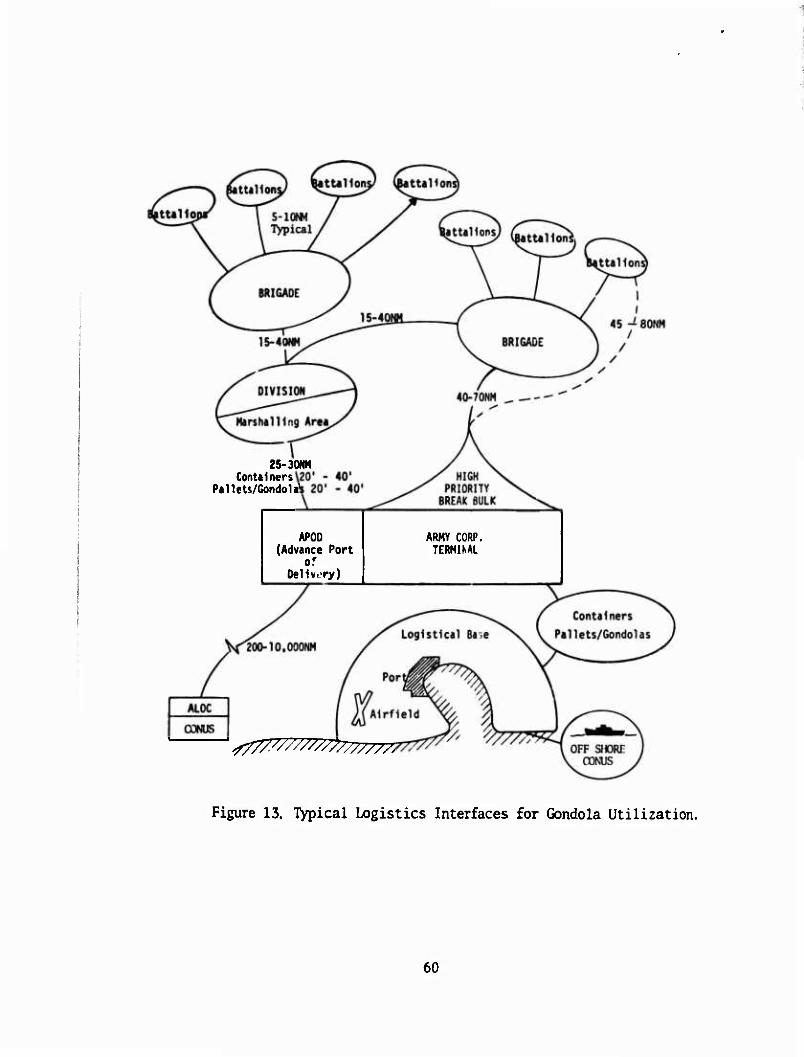
25-30NM Containers
Pallets/GondoW
APOD (Advance Port
of Dellwory)
ARMY CORP. TERMIKAL
200-10,000NM
Per
i^Airfield
Figure 13. Typical Logistics Interfaces for Gondola Utilization.
60
WW^*^-' - W&mmPSi^wmmmab, mmmm*v&mr&*mm^ ■*yM'.'*ifyfm-i&rtwvv?&4wwa*^^
depicted in Figure 13. The role of the gondola is further extended in its use as a shuttle vehicle in transporting combat vehicles over inter rupted surface routes such as craters or unserviceable bridges. Addition- ally, the gondola use in ship-to-shore off-loading is a key function when off-loading vehicles and equipment in particular multiple unit loads. Personnel familiar with rigging other external cargo for helicopter trans- port should minimize errors of judgement, since fixed load points are available. However, weight and balance provisions should be made avail- able to limit center-of-gravity unbalance. This could be accomplished at the transfer terminal but would require care in judicious placement of cargo in the forward areas. Tie-down provision for break-bulk cargo and equipment will be integral to the pallet base. Attachment to the aircraft will be made by slings and pendants which have the capacity to support the potential payload.
In Flight
Operation of the helic r>tci s uld be typical for external cargo operations, Experience should be demonst:- -ed prior to flying tactical supply mis- sions.
Returns
Return of the empty gondola can be accomplished in multiples since most of the concepts will stow at one-fourth the cube of the deployed mode. The goal of the design should allow the rotum of four empty gondolas in the volume occupied by one fully load i gondola.
Terminal Requirements
The gondola terminal handling requirements are similar to those exper- ienced for containers. The open frame upperstructure permits ease in roll-on/roll-off loading and unloading. This is accomplished with stan- dard shallow ramps or by bridging with available dunnage material. The volumetric size and payload are nearly identical to that experienced for containers. The loading and unloading can be accomplished by similar means. However, more flexibility is permitted by the gondola since the top is open and since the ends and, in some concepts, the sides are remov- able. The use of hand trucks and small forklifts for loading and unload- ing can be used when available. This equipment is standard TOE for a terminal transfer unit. However, the movement of a fully loaded gondola within the terminal cannot be accomplished with existing forklift capacity. Therefore, terminal transfer units must be equipped with mobile lifting equipment with 25,000- and 60,000-lb capacity. The mobile lifting equip- ment need not be forklift devices but could be gantry or straddle carriers, which engage the gondola at the lift points used by the helicopter.
61
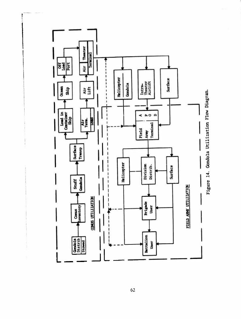
I
Hi
§
4J
I
I •H
[a^sj ■
62
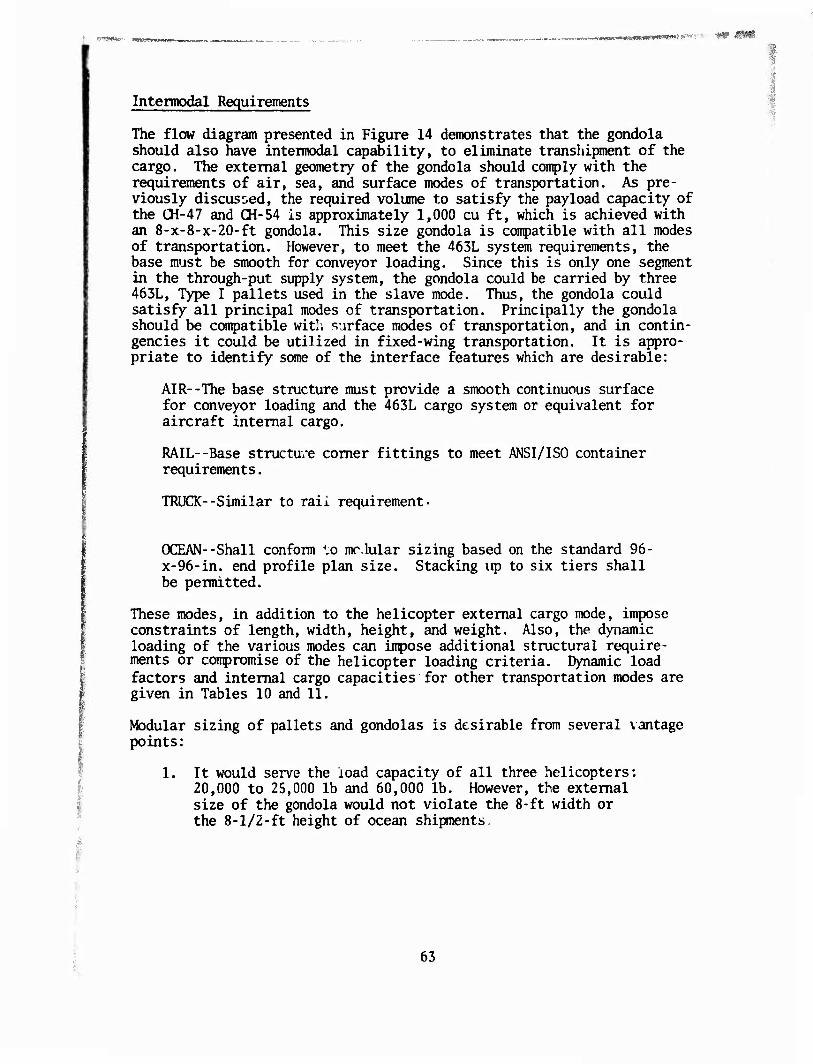
Intermodal Requirements
The flow diagram presented in Figure 14 demonstrates that the gondola should also have intermodal capability, to eliminate transhipment of the cargo. The external geometry of the gondola should comply with the requirements of air, sea, and surface modes of transportation. As pre- viously discussed, the required volume to satisfy the pay load capacity of the CH-47 and CH-54 is approximately 1,000 cu ft, which is achieved with an 8-x-8-x-20-ft gondola. This size gondola is compatible with all modes of transportation. However, to meet the 463L system requirements, the base must be smooth for conveyor loading. Since this is only one segment in the through-put supply system, the gondola could be carried by three 463L, Type I pallets used in the slave mode. Thus, the gondola could satisfy all principal modes of transportation. Principally the gondola should be compatible with surface modes of transportation, and in contin- gencies it could be utilized in fixed-wing transportation. It is appro- priate to identify some of the interface features which are desirable:
AIR--The base structure must provide a smooth continuous surface for conveyor loading and the 463L cargo system or equivalent for aircraft internal cargo.
RAIL--Base structure comer fittings to meet ANSI/ISO container requirements.
TRUOC--Similar to rail requirement-
OCEAN--Shall conform ".o modular sizing based on the standard 96- x-96-in. end profile plan size. Stacking up to six tiers shall be permitted.
These modes, in addition to the helicopter external cargo mode, impose constraints of length, width, height, and weight. Also, the dynamic loading of the various modes can impose additional structural require- ments or compromise of the helicopter loading criteria. Dynamic load factors and internal cargo capacities for other transportation modes are given in Tables 10 and 11.
Modular sizing of pallets and gondolas is desirable from several vantage points:
1. It would serve the load capacity of all three helicopters: 20,000 to 25,000 lb and 60,000 lb. However, the external size of the gondola would not violate the 8-ft width or the 8-1/2-ft height of ocean shipments
63
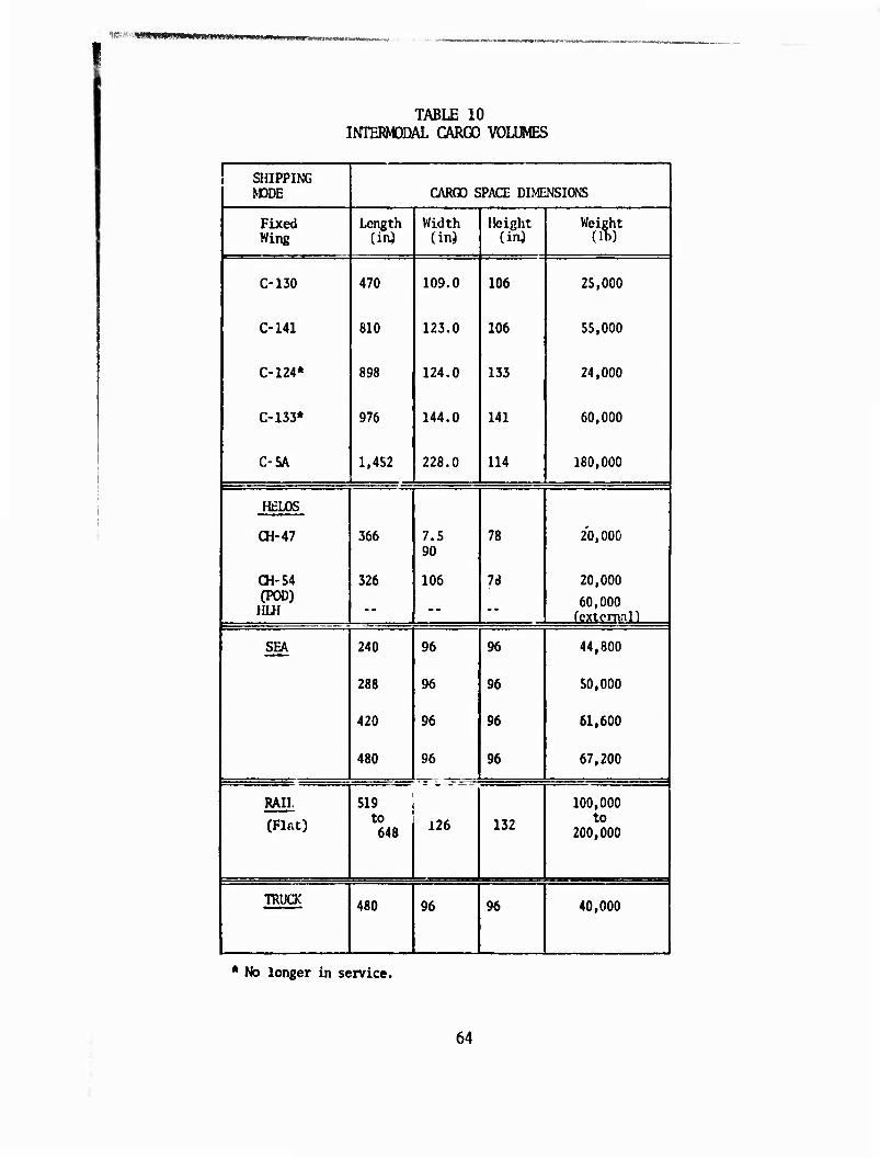
^'■■*-^¥*<tit&s&»*iSHimv^ ww.**
TABLE 10 INTERMODAL CARGO VOLUMES
1 SHIPPING } KDDE CARGO SPACE DIMENSIONS
1 Fixed Wing
Length (inj
Width (in)
Height (in)
Weight (lb)
j C-130 470 109.0 106 25,000 |
1 C-141 810 123.0 106 55,000
| C-124* 898 124.0 133 24,000
C-133* 976 144.0 141 60,000
i C-5A 1,452 228.0 114 180,000
! HELOS
1 CH-47 366 7.5 90
78 20,000
1 ai-54 I (POD)
HLH
326 106 7<J 20,000
60,000 fextcmal) 1
SEA 240 96 96 44,800
288 96 96 50,000 I
420 96 96 61.600
480 96 96 67,200 j
! RAIL 519 100,000
j (Flat) to 648 126 132 to
200,000
! TOUCK 480 96 96 40,000 I
* No longer in service.
64
■ ST' ?M8gr. W'W^''"««fs»««r»'/' ™m!f£%^jmymim&-^!e:?*'-- . .. .
TABLE 11 INimDDAL DYNAMIC LOAD FACTORS **
1 Direction of Load Relative to the Axis of Container
Terminal Operations MARINE HIGHWAY RAIL
AIR PHEb WING
Downward Upward Lateral Longitudinal
2.0 0.0 0.2 0.7
1.8 0.0 0.6 0.6
1.7 0.0 0.1 0.7
1.5 0.0 0.3 1.8
3.0 l.il 1.5 3.0*
MPer AN STD. Ml 5.1 1970
i * 3g Per MIL-A-842:C when not loaded at same level as crew
2. Modular to Air, Ocean, Rail, and Highway
Interface dimensional requirementi. can be achieved with an 8-ft wide load, which is standard for both highway and ocean shipment. Current aircraft would accept slightly wider loads, or twice this width in the case of the C5-A. Modular lengths with respect to aircraft caz-go length would accept 10-ft multiples. The 10-ft length module would utilize more than 75% of the allowable cargo length of the five principal fixed-wing aircraft presently available. Invariably, fixed-wing cargo aircraft are weight limited; therefore, the nominal load density of less than 20 Ib/ft^ would fully utilize the fixed-wing capacity. In the C5-A, as an example, could be stowed six 8-x-8-x-40-ft pallet/gondola loads equaling 15,360 ft^, assuming that a normal payioad of 180,000 lb yields a density of 11.75 lb/ft3. This load density is approximately one-half the average cargo density of 20 to 25 lb/ft3.
Intermodal requirements of the gondola can be achieved by re- stricting the width to 8 ft and the height to 8-1/2 ft or less. Thii restraint in no way compromises the gondola in its mission of transporting break-bulk cargo as a slung load on the heli- copters. An interior clearance width of 9 ft would be more compatible with larger vehicles.
65
OPERATION SUITABILITY
Operational suitability of the gondolas must be demonstrated by the following criteria:
1. Sufficient capacity
2. Structure to support maximum pay load with attendant load factor
3. Reliability
4. Maintainability
5. Transportable by one or more other modes
6. Environmental
The gondola concept selected as the preferred design meets the of ,ional goals presented. Its primary operation will consist of transporting noncontainerizahle cargo to include vehicles and equipment.
UTILIZATION
The gondola will normally be utilized in resupply operations with "s principal applications predicated on the helicopter. This is not to pre- clude mtermodal operation nor the fact that the H1H may be used in direct supply to forward area user organizations. However, there appears to be more efficient use of each size gondola and helicopters at partic- ular segments of the resupply system. The continuous 20- and 40-tt gondolas accept nearly all vehicles and equipment organic to a road combat unit. The gondola design preserves the intermodal capability while satisfying the helicopter external cargo requirements. Therefore, the gondola could be employed directly at the port terminal when tranship- ment of high-priority cargo is required, or it could interface at any of the surface transportation terminal points. It appears that the gondola has all the capability of a container except protection of contents from weathering while providing oiing load capability and safety and effi- ciency of empty return flight. The tare weight of the gondola is consid- erably less than that of containers of comparable size. The selected gondola design concept can interface with all modes of transportation within the existing system.
Operational suitability of the three helicopters utilizing gondolas is summarized in Table 12. Utilization of the helicopters is predicated on mission radius suitability, payload, and exposure risk from enemy engagement.
66
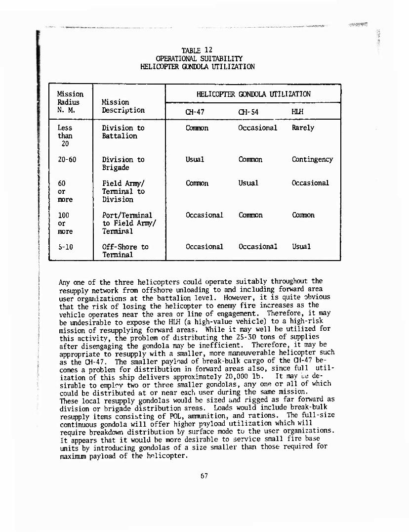
'> *»)r>»|,"** Wn*»!«....*■—.»., ^ ^-j.* ■^r*?»^''"'^•,(t*<TW*'y# ■
TABLE 12 OPERATIONAL SUITABILITY
HELICOPTER GONDOLA UTILIZATION
Mission Radius N. M.
Mission Description
HFMCOPTER GONDOLA UTILIZATION
CH-47 CH-54 HLH
Less than
20
Division to Battalion
Ccramon Occasional Rarely
20-60 Division to Brigade
Usual Common Contingency
60 or more
Field Army/ Terminal to Division
Common Usual Occasional
100 or more
Port/Terminal to Field Army/ Terminal
Occasional Common Common
5-10 Off-Shore to Terminal
Occasional Occasional Usual
Any one of the three helicopters could operate suitably throughout the resupply network from offshore unloading to and including forward area user organizations at the battalion level. However, it is quite obvious that the risk of losing the helicopter to enemy fire increases as the vehicle operates near the area or line of engagement. Therefore, it may be undesirable to expose the Hm (a high-value vehicle) to a high-risk mission of resupplying forward areas. While it may well be utilized for this activity, the problem of distributing the 25-30 tons of supplies after disengaging the gondola may be inefficient. Therefore, it may be appropriate to resupply with a smaller, more maneuverable helicopter such as the CH-47. The smaller payload of break-bulk cargo of the CH-47 be- comes a problem for distribution in forward areas also, since full util- ization of this ship delivers approximately 20,000 lb. It may be de- sirable to employ two or three smaller gondolas, any one or all of which could be distributed at or near each user during the same mission. These local resupply gondolas would be sized and rigged as far forward as division or brigade distribution areas. Loads would include break-bulk resupply items consisting of POL, ammunition, and rations. The full-size continuous gondola will offer higher payload utilization which will require breakdown distribution by surface mode to the user organizations. It appears that it would be more desirable to service small fire base units by introducing gondolas of a size smaller than those required for maximum payload of the helicopter.
67
Minimum exposure of the helicopter would suggest simply unhooking in hover and returning for another load. The empty gondolas could be recovered when the area becomes more or fully ".ecured. Therefore, the return leg of une mission could be flown at V , »dth every third or fourth return leg designated as an empty gondola return. If the HLH was employed in forward areas, resupply distribution flexibility is decreased while risk value increases.
Gondolas used in rear areas (brigade and above) need not have the clus- tered/breakdown for local distribution but could be compatible with all transportation modes if the 9G fixed-wing requirement wet? waived. This requirement imposes a severe penalty on the design, particularly tare weight. The pallet can be sized for width compatibility to the ANSI/ISO standard size of 8-x-20-ft or 8-x-40-ft plan areas while accepting loads to a height of 8 ft and 8.5 ft respectively. This sizing would be com- patible with highway, rail, and maritime transportability. It crash survivability of the 9G load by fixed-wing aircraft is not a requirement, the same size pallet/gondola could be utilized in the ALOC system. This size pallet/gondola would also be compatible with the container ship cell dimensions. Stackability for ocean shipment does not appear to induce excessive tare weight in the structure. However, the intermodal design shall not significantly compromise the basic objective of the resupply mission of the helicopter. Sizing methodology for helicopters and oth^r modes of transportation appears in the section on Gondola Performance. Additional suitability requirements shall consider forklift openings for terminal handling and ground relocations, and smooth treadways for conveyor handling and locking devices to American National Standard Institute/ International Standard Organization (ANSI/ISO) requirements.
RELIABILITY-MAINTAINABILITY
Reliability and maintainability requirements will be in accordance with AR 705-50. The goal of the design concents is to provide a gondola that avoids the uso of thin-gauge materials, with maximum utilization of rugged structural members having relatively high resistance to abuse and environmental degradation.
Reliability and maintainability of the gondola are predictable from the perfomance criteria established for the design, except for fatigue en- vironment. A close approximation of the gondola service life can le predicted once the fatigue loads are measured. However, an assessment of the operational environment suggests that the gondola be constructed of heavy-gauge material such as extrusions, forging and castings to mini- mize the percentage loss of thickness due to abrasion, corrosion, etc., that would significantly compromise total structure integrity. Where such materials and/or thickness do occur, they shall be easily repaired or replaced with minimum complexity. Therefore, the types of structures conceived should demonstrate these attributes.
68
ffKKwmBpmtr+sii'imf i, »iaM;»'^'r«CTWWCT^:''W'»P'»gBW>y • *«1W^3W'*rW'WJSW*f^?WW!WfW^<P.'^P^«9^P*^
The reliability goal of the gondola system is to demonstrate a 95% prob- ability of completing the helicopter mission. As shown in the section on mission requirements, the gondola could be utilized for several seg- ments of the supply system. However, the forward resupply mission appears as critical as any of the other missions which interface at some time during the delivery cycle with the helicopter. Assuming 24-hour utilization at 2/3 yearly availability suggests that the gondola be used for 5,840 hours. A typical forward resupply mission would consume approx- imately 7 hours:
Load Rig and Attach 3 hours
Flight Delivery 1 hour
unload and Prepare for Return 2 hours
Flight Return 1 hour
TOTAL 7 hours
Therefore, a gondola should complete 834.2 missions annually. Assuming a maintenance ratio of .1 would allow 58.4 maintenance hours annually. This maintenance hour estimate is over 501 of the fabrication assembly time allotted for most concepts. Due to the relatively simple structure, local repairs by a mechanic should be permitted to complete a miss'oi.. The use of pinned or bolted connections on the side, end, and top trame members should permit local replacement by the user organization. Scheduled maintenance should be permitted on an annual basis. It is pro- jected that local maintenance could be accomplished within 1 hour and support maintenance within 3 hours. Preventive maintenance such us painting and replacement of fasteners, as required, could be accomplished during annual maintenance. Except for the helicopter mode, the gondola and container experience similar damage from intermodal transportation, terminal handling, and environmental degradation.
INTERMODAL DAMAGE
Of all the transportation modes other than by helicopter, the maritime conditions appear to be the most severe. However, the load factors due to rail humping and fixed-wing crash survivability would be more severe than the helicopter mode. The maritime conditiuis which impose the most damage occur when the gondola is lashed above deck. This becomes par- ticularly detrimental when the gondolas are stacked, with the higher stack imparting racking and rolling motions which could damage the struc- ture. It should be noted that the crash survivability and rail humping load factors are not considered. These load factors are 9.0G and 25.0G respectively. If these extreme conditions were included in the design criteria, a substantial tare weight penalty would be imposed.
69
TERMINAL AND YARD DAmGE
Terminal and yard handling is a major cause of damage experienced in the container industry. This frequently occurs when provisions are lacking for forklifting or gantry acquisition. Another frequent source of damage is puncture of thin-gauge materials. To avoid these pitfalls, the gondola has both forklift tineway and toplifting load points.
It is desirable to have both capabilities except where the gondola is utilized beyond the terminal areas. No thin-gauge materials such as sheet stock is utilized to avoid susceptibility to puncture, tear, etc., or where abrasion, erosion, and corrosion would cause a significant per- centage reduction in load-carrying ability. Chemical conversion coatings anu subsequent protective finishes should be used.
ENVIRONMENT
Environmental degradation provisions are inherent in the selection of the materials and the surface protection afforded by the design. It is assumed that the gondolas would operate in a marine environment at the cli- matic extremes of AR 70-38 categories 1, 2, 5, and 6. The choice of ma- terials and judicious use of thin-gauge materials must be such as to avoid corrosive and thermal degradation. The gondola shall have no restrictions to preclude operation in extreme climatic or atmospheric conditions. Corrosion and abrasion are the two most active degrading el- ements acting on the equipment. In addition, the degradation to fatigue loads must be considered. True assessment of the fatigue loads can only be achieved by performing a flight strain survey. From such a survey the stresses and a predicted frequency of occurrence could be estab- lished. Analysis has addressed limit and ultimate load factors. In satisfying these extreme load conditions, the structure would have a sig- nificant fatigue life of several years. Using a dynamic load factor of 3.0 superimposed on a 1.5 ultimate safety factor should provide suffi- cient structure to carry high frequency but relatively low amplitude vibratory stresses.
70
■ •■:• W. HWHIIUWU "— ~~ ■ —•■ ■ ,.,..-■ „•,..,-.*M..;.->.-!«»»'rr:
PERSONNEL EFFECriVENESS
Utilization of the pallet/gondola should inprove personnel effectiveness when moving cargo by helicopter, slung externally. Previous evaluation strongly suggests that many vehicles and equipment were carried as single items or required complex rigging procedures. This imposed a severe pay- load efficiency penalty on the helicopter. In addition, it required the rigging and attachment time to occur four times to achieve full load capacity of the CH-47 and CH-54. While loading, rigging, and attachment times for nets are difficult to quantify, they are strongly suspected to be significantly greater than that for a single gondola load. Optimized use of the helicopter gondola system may best be ex- ploited wheii operating from an APOD or rear position terminal serviced by a typical Terminal Transfer Co.11 The gondola should not only promote manpower and helicopter efficiency, but minimize rigging errors resulting in damage to or loss of cargo. The gondola will either enclose the cargo or provide tie-down restraints at specified intervals. In addition, the load lift points will eliminate errors in judgement which frequently occur in rigging individual vehicles and equipment. Prescribed rigging and cargo restraining instructions should be carried out with minimal guidance at the Terminal Transfer Co.
When using the gondola in contingency tactical deployment of equipment and vehicles, the load should be inspected for proper r^^traint and distribution. This could be accomplished by anyone witn cue minimum knowledge of standard aircraft rigging practices. Utilization of the gondolas in rear areas to a point where they are introduced at CONUS shipments demonstrates a vast potential by avoiding the transfer of the cargo at each transportation mode interface.
The selected design concept utilizes standard aircraft tie-down restraint? which permit th? use of standard restraint hardware. In addition, the loading and unloading of the gondola is improved over normal containers due to quick-release pinned structure. Vehicles and equipment can be loaded similar to CONUS shipment of break-bulk cargo, thereby eliminating onboard rigging. The attendant reductions in manpower requirements and the efficiency of unloading should be demonstrated.
Personnel effectiveness should be demonstrated particularly by prerigged gondolas with multiple units of vehicles and equipment. This will eliminate individual item rigging. This factor becomes particularly important when off-loading equipment from ship to shore.
71
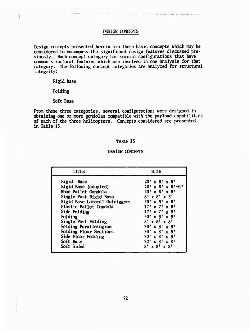
DESIGN CONCEPTS
Design concepts presented herein are those basic concepts which may be considered to encompass the significant design features discussed pre- viously. Each concept category has several configurations that have common structural features which are resolved in one analysis for that category. The following concept categories are analyzed for structural integrity:
Rigid Base
Folding
Soft Base
From these three categories, several configurations were designed in obtaining one or more gondolas compatible with the payload capabilities of each of the three helicopters. Concepts considered are presented in Table 13.
TABLE 13
DESIOI CONCEPTS
TITLE SIZE
Rigid Base 20» x 8' x 8' Rigid Base (coupled) 40' x 8» x B'-ö" Wood Pallet Gondola 20« x 8» x 8' Single Post Rigid Base 8' x 8' x 8' Rigid Base Lateral Outriggers 20' x 8' x 8' Plastic Pallet Gondola 17« x ?• x 8« Side Folding 17» x 7' x 8' Folding 20» x 8* x 8' Single Post Folding 8' x 8» x 8* Folding Parallelogram 20» x 8» x 8' Folding Floor Sections 20' x 8' x 8» Side Floor Folding 20» x 8' x 8' Soft Base 20» x 81 x 8' Soft Sided 8' x 8' x 8'
72
$pg$£v-h *^• ^^sr^^^'m-^^^-^^y^:s^^^rpf-v.-..,?,.,-,.. ■'■'•■-■■■ ttwvffr ■ P« ■.-*. -Lf^.-«.».
DESIGN BRIEF
A brief narrative discussion of each of the concepts is presented to point out significant features which contribute to or detract from overall per- formance of the gondola concepts. Significantly, all the concepts util- ize standard structural shapes of aluminum alloy 6061-T6. This choice of material achieved nearlv the highest rating in strength to weight and cost of several mater;i: ;andidates rated in the section on Materials and Methods of Construction. Joints ere riveted, bolted, or welded, with welded connections used sparingly to avoid the strength reduction. Attachment fittings are both cast steel and aluminum alloys. In satis- fying the reliability and maintainability, the gondola is conceived using rugged structural shapes that have a high resistance to mishandling, which is typical of cargo transfer operations.
In other concepts, relatively inexpensive pallets or nets were utilized to accoranodate replaceability. In general, the concepts embody ruggedness for long life or replaceability at low cost.
RIGID BASE (20-x-8-x-8-ft)
This unit provides a 20-x-8-ft continuous, uninterrupted floor and vol- ume. Four lift points are located coincidental with the ISO comer fit- tings. The unit can be transported by all surface modes incidental to the maritime container. It could be transported by fixed wing when used in conjunction with the 463L pallet as a slave. Two units may be con- nected at their sides to develop sufficient capacity for the HIH.
RIGID FLOOR (40-x-8-x-8!s-ft)
Similar to the basic 20-ft-long rigid base, this concept connects two 10-ft end sections to a 20-ft center body. The height was increased to provide sufficient cubic capacity. The end connections are accom plished with a standard ISO fitting. The advantage of the 40-ft length is desirable to develop payload capacity of the HLH and for transporting vehicles. It is compatible with all surface modes of transportation and could be delivered by fixed wing using the 463L pallet as a slave.
WOOD PALLET GONDOLA (20-x-8-x-8-ft)
This concept has some of the construction features of the 20- and 40-ft- long rigid-based gondolas, but it integrates a standard wood pallet as a part of the floor surface. Preloaded pallets can be placed on the gon- djla structure. The base structure becomes somewhat heavier, but its utilization of the basic wooden pallet should prove to be highly effective. It coul^ also be coupled on the side to achieve capacity near that of the HLH.
73
SINGLE-POST RIGID BASE f8-x-8-x-8-£t)
This concept features a rigid base with a removable center post which allows the empty base to be stacked for empty return. Although the unit does not have the single capacity of any of the helicopters, it can be piggy-backed to achieve near capacity of the CH-47 and CH-54 helicopters. It allows two-point distribution for supplying smaller units.
RIGID BASE - OUTRIGGER SUPPORTS (20-x-8-x-8-ft)
This concept has a floor structure similar to the 20- and 40-ft rigid- base gondolas; however, the side racking loads were reacted by a retract- able outrigger support. This method proved to be impractical for the high reaction load and was rejected. Since the lift points were located at the quarter span, the other alternative was to place a diagonal brace across the lateral span, which would encumber the free areas. Later iter- ations of the design proved to have less tare weight when the side frame was continued to the end.
REM3VEABLE PLASTIC PALLETS (17-x-7-x-8-ft)
This concept was designed around a cormercially available polystyrene pallet. The support structure is similar to that used for the wood pallet. It was initially conceived to support the pallet about its edge, which proved to be inadequate. However, with more support structure and added weight, the pallet could be utilized. The advantage of the plastic pallet is its stackability and potentially lower life-cycle cost than that of the wooden pallet.
SIDE FOLDING (20-x-8-x-8-ft)
This concept allows the sides to fold over the base and eliminates loose side parts when transported empty. This type of side structure could be utilized on any of the rigid-base concepts, with some modification required on the 40-ft length.
FOLDING BASE (20-x-8-x-8-ft)
This gondola concept allows the gondola to be stowed to nearly 251 of its deployed capacity by unpinning the end diagonal bracing. Three of the empty units can be connected in the folded configuration and transported on a fourth for empty return. The floor system aside from the hinged cross member is similar to the basic 20- and 40-ft-long gomolas.
SINGLE-POINT FOLDING (8-x-8-x-8-fO
This concept folds about a center post to slightly over 3-x-8-ft and can be stowed in approximately 5% of its load capacity. Its low stowage density would allow it to be carried as internal cargo in the CH-47. Two of these units slung in piggyback would provide near payload capacity of the CH-47. However, due to the center post, the unit has limited equipment utility and no vehicle transport.
74
1B*l*l'*#*SKmSimmi*mmamm
PARALLELOGRAM FOLDING (20-x-8-x-8-ft)
A parallelogram folding concept has two salient features which become inefficient for structural integrity. It requires a longitudinal center member about which a single-point hinge must rotate. Since it is both a tension and compression pivot point, it is more expensive than a horizon- tal hinge which is kept in tension. The center longitudinal member and the vertical hinges add weight and cost and degrade reliability, disad- vantages which are not appreciably offset by its stowability over other concepts.
BASE SIDE AND END FOLD (20-x-8-x-8-ft)
The side and end folding concept offers improved stowability when empty. However, its load lift points occur over the floor area, which precludes the transport of vehicles and many equipment items. The use of additional members to accomplish folding further detracts from its reliability and payload effectiveness. In summary, the encumbered floor and free volume severely handicap its effectiveness.
SIDE FOLDING (20-x-8-x-8-ft)
This concept allows for folding the sides over the center section to reduce stowage. It has growth potential to double the floor width to pro- vide capacity near that required for the HLH. The concept again encumbers the floor and the desired free internal volume. Little or no advantage is achieved for weight reduction or empty stowage bv the folding side struts since the structure requires two longitudinal members. As shown in the analysis, folding, cantilevered, load strut structure is less efficient than a rigid floor. There is no distinct advantage for this concept.
SOFT BASE GONDOLA (20-x-8-x-8-ft)
The soft base concept is in effect a rigidized net which will contain cargo similar to a net but would virtually eliminate induced crushing of the loads. The structure base members are pinned, to which netting is attached. The base is attached to the upper acquisition structure by cable or chain. The structure could carry all previously netted loads and equipment. An on-site floor could be overlayed with planking or plywood to facilitate other equipment. Its ease in fabrication, low cost, and some weight sav- ings are advantages over rigid and folding base concepts. However, it has limited intermodal capability and cannot transport vehicles.
M
SOFT BASE ERECTOR (8-x-8-x-8-ft)
This concept is an attempt to utilize inexpensive nets but to eliminate the undesirable crushing loads. The base and upper structure are rigidized by standard structural members to support the net. Since the size is 8-x-8-x-8-ft, provisions are made to couple two together, providing near capacity for the CH-47. To minimize upper support structure, a sling leg is required at each comer. The soft sides allow stowage to approximately
75
;X":*;»sv ■WS&f.),fl'm-MjSf^%vm^iim>!iiyi^!sm*smmstmimKtmi>^^.«
15% of its deployed volume. The unit can be forklifted and has limited intermodal capability.
OONCEPT EVALU/VTION
The above design concepts were rated by a comparative evaluation system which weighted the various features to accumulate 100 points maximum. The evaluation conmittee was composed of the project engineer, designers, and an analyst who were familiar with the design goals of the study. The rating system is presented below.
CONCEPT EVALU/VTION OOMPARATIVE/WEKKrED FACTORS (lOO-POINT TOTAL)
1. Design and Payload Acquisition (15 points)
Three points for the following features:
1. Provides cube capacity over continuous floor surface 2. Interior unencumbered by support structure 3. Simplest structure configuration 4. Ease in tie-down restraint 5. Multipoint attachment
2. In-flight Stability (15 points)
Three points for the following features:
1. Provides two or more lift points 2. Lift point(s) above CG 3. Least aerodynamic effect (drag) 4. Low drag, high porosity when empty 5. Permits quarter span CG travel
3. Interface Compatibility (15 points)
15. Conpatible with all interfaces of the supply network 10. Excludes certain-interfaces of the siqpply network 5. Compatible with helicopter mission only
4. Logistical and Technical Mission Requirements (10 points)
10. Satisfies three helicopters 6. Satisfies two helicopters only 2. Offers limited capability
5. Production Costs (10 points)
10. Lowest cost of all concepts 8. In first quartile of cost ranking 6. Median cost of all concepts
76
/:: *?SR*W? ».!a®«raw>?»Mra¥Wtjlfli(Söw^ ^ .J!mm
4. In third quartile of costs of all concepts 2. Highest cost of all concepts
6. Weight (10 points)
10. Highest pay load per unit tare weight 5. At or near median of all concepts 0. At or near heaviest
7. Personnel Efficiency (10 points)
10. Least time per unit cargo load 8. In first quartile of time consumed of all 5. Median time, all concepts 2. In third quartile, all concepts 0. Highest time of all concepts
8. Support Systems Compatibility (5 points)
5. Can be integrated into supply system with minimal peripheral equipment
3. Requires limited introduction of support equipment 2. Capable of modification but compromises utility 0. Limited compatibility
9. Reliability and Maintainability (5 points)
5. Very reliable, easily maintained 3. Reliable with moderate maintenance 2. Reliable but has vulnerable components 0. Potentially unreliable, requiring frequent maintenance
10. Environmental and Climatic Limitations (5 points)
5. Suitable for all weather operations 2. Suffers degradation due to corrosive and abrasive degradation 0. Potentially unsuitable in climatic extremes
77
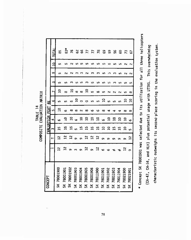
X t—I
'* o
-I =3 00 _l
I— »—I
o S: o
_ « ^ J in co iP CM <n rv I-* 00 en CTi *£> o CO rv
1 ^ CO 1^ lO lO iv. iv. rv io in in m rv in
ft in in CM in in in m in in in in in CM CM
r in CM CM n CO CM CO CO m lO CO in CM CM
CO in in CO in in CO in in in W) CO in in in
o O O r». c-l 00 i-l 00 00 <—i in CO in CM CM CM in CO
o O o o UJ UJ in in in t-H o o in in t—4 in in in t-H t-H
QC
in o
vn 00 00 CO 00 vo in 00 ^i- «3- ^j- cn on
o o o o o o o o o o o «s- VD -i f-t ID <—i 1—1 t-H t-H m i-H t-H t-H t-H vo H a ' 3
in in in in in in in o o in m o ^ ••> i—i t-t t-i in i-i »—i t-H t-H t-H I-l t-H t-H t-H in
<\j CM CM CM CM CM CM CM r-4 i-l t-H a> en t—» t-H i—i cr> a\ cn cn <T> t-H
i—t CVJ CM CM CM <M i-H t-H Ol co a\ t-H cr> t-H io VO -a -a t-H cn
o t-H CM CO *t m vo o t-H CM CO ^t o •-' 1 o Ü O o o o o O o o o o o o 1 <T> CTl CT> <T> o^ CT» en a^ (T> cr> CT> CTt «T> Ol 1
t-< •-I i-H r-t t-H t-H t-H t-H t-H i-l t-H t-H 1
1— f O O O o o O o t-H t-H T-i I-H t-H CM CM 1 a. O O
^ o § o o O O O O O O o 1
UJ 00 Ü0 00 00 00 CO 00 00 CO on on cn <-> 1 r^ 1»» fv r^ l-v rv IV. IV rv rv i^ rv 1 z 1 o i ^ ^ *i it ^ v: ^ ü ^ ^ ü ^ V v: 1 1 CO CO CO 00 CO oo oo CO 00 CO 00 00 co CO 1
l/) i.
o. o
<u c Ol
Ul
<u, w OJ -c 0) L. E c
o JC 0) •r* •M > -M
o <o ^— 3 ^— to r— <o T- (0
£ > u 1— <u o
M- 0) • -C c in +J o <t
•I— h- c 4-» »- •r- <a =3 hj o>
•r— -C c r— 4-> 'f— •t— •i— t. •M 2 o 3 o
a» lO 10 CT •M <o 0) •i— VI o
3 <a O 4-»
<o a. i
0) •r»* -a => ■M c ■o C o
CO u ■CT •M 01 (U O to ••-» O. O 10 (U V» ■M
r— 3 •r— 0) r— to a. 10
to ■'"^ o> (O 3i *r» ? -j OJ
a: 3t t-H •M O TD 3 <T> c O I-H ■a o O O •« •r» 00 ^t ■I-» tv in Ifl
^ X f. 00 o 0)
f-> « o a. i^ «J <u ^i- %. o «o c 3: x: o o o o ^^^
78
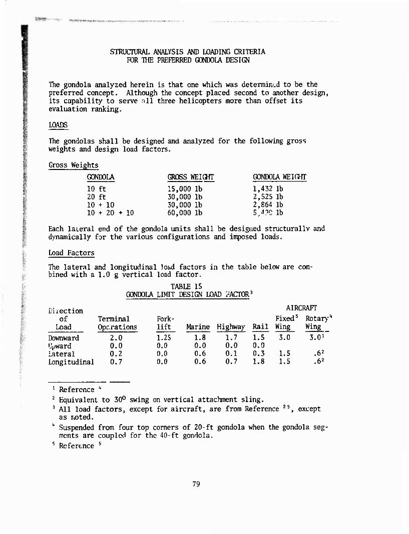
-v.»^, t?fe,VSfiifl*i,*r;!"v<*i-w:-'^j*Tv .-tTMow-Wi—MJ*:*-^«»*»«
STRUCTURAL ANALYSIS AND LOADING CRITERIA FOR THE PREFERRED GONDOLA DESIGN
The gondola analyzed herein is that one which was determin.d to be the preferred concept. Although the concept placed second to another design, its capability to serve all three helicopters more than offset its evaluation ranking.
LOADS
The gondolas shall be designed and analyzed for the following gross weights and design load factors.
Gross Weights
GONDOLA GROSS WEIGHT GONDOLA WEIGHT
10 ft 15,000 lb 1,432 lb 20 ft 30,000 lb 2,525 lb 10 + 10 30,000 lb 2,864 lb 10 + 20 + 10 60,000 lb 5,^0 lb
Each lateral end of the gondola units shall be designed structurallv and dynamically for the various configurations and imposed loads.
Load Factors
The lateral and longitudinal load factors in the table below are com- bined with a 1.0 g vertical load factor.
TABLE 15 GONDOLA LIMIT DESIGN LOAD rACTOR3
Direction AIRCRAFT
of Terminal Fork- Fixed5 Rotary1* Load Operations lift Marine Highway Rail Wing Wing
Downward 2.0 1.25 1.8 1.7 1.5 3.0 3.01
Upward 0.0 0.0 0.0 0.0 0.0 Lateral 0.2 0.0 0.6 0.1 0.3 1.5 .62
Longitudinal 0.7 0.0 0.6 0.7 1.8 1.5 .6Z
Reference **
Equivalent to 30° swing on vertical attachment sling. All load factors, except for aircraft, are from Reference 25, except as noted.
Suspended from four top comers of 20-ft gondola when the gondola seg- ments are coupled for the 40-ft gondola. Reference 5
79
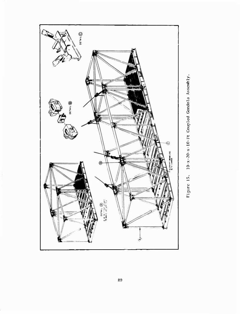
i-H
■S 5
<
o c
13 O
5
o (VI
CO
8(1
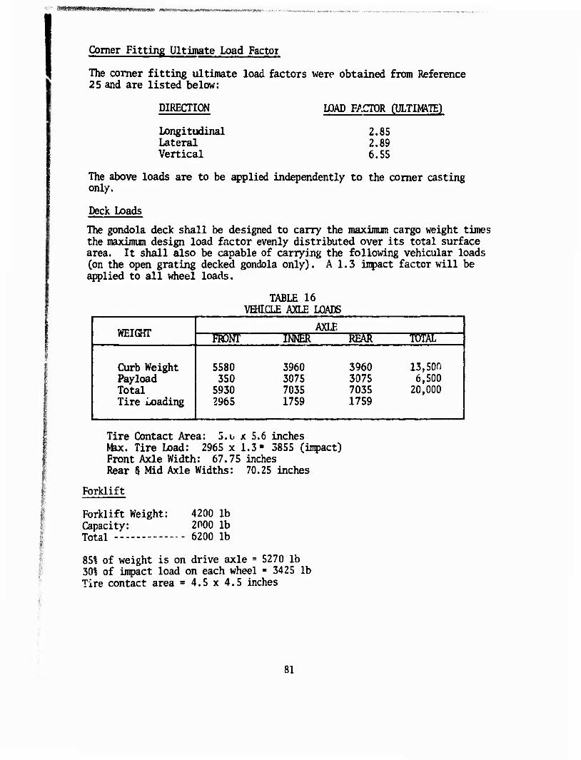
HHMWHnMMMBMnMMMn' tammmmmm* < rmm*™**'-**?™*'^!''*?' -
Comer Fitting Ultimate Load Factoi
The comer fitting ultimate load factors were obtained from Reference 25 and are listed below:
DIRECTION
Longitudinal Lateral Vertical
LOAD FACTOR CULTIM/VIE)
2.85 2.89 6.55
The above loads are to be applied independently to the comer casting only.
Deck Loads
The gondola deck shall be designed to carry the maximum cargo weight times the maximum design load factor evenly distributed over its total surface area. It shall also be capable of carrying the following vehicular loads (on the open grating decked gondola only). A 1.3 impact factor will be applied to all wheel loads.
TABLE 16 VEHICLE AXLE LOADS
WEIGHT AXLE
■rorr ismc "REäT ■TOST
Curb Weight Payload Total Tire Loading
5580 350
5930 2965
3960 3075 7035 1759
3960 3075 7035 1759
13,son 6,500
20,000
Tire Contact Area: 5.o x 5.6 inches Max. Tire Load: 2965 x 1.3" 3855 (inpact) Front Axle Width: 67.75 inches Rear § Mid Axle Widths: 70.25 inches
Forklift
Forklift Weight: Capacity: Total
4200 lb 2000 lb 6200 lb
85% of weight is on drive axle = 5270 lb 30% of impact load on each wheel = 3425 lb Tire contact area = 4.5 x 4.5 inches
81
Stacking
The gondolas shall be capable of withstanding loads imposed by stacking the gondolas six high at their maximum gross weights. The bottom con- tainer is assumed to be supported equally by the four lower comer fittings. The 1.8 g downward load factor shall be applied to the stacked gondolas.
Racking
The gondolas shall be capable of withstanding racking loads applied longi- tudinally or laterally at the upper comers and restrained by the lower ccmers. This load shall be .6 times the container gross weighs A 1.0 g downward load is also acting on the container during the racking load.
Tie-Down Rings
The cargo tie-down rings and immediate backup structure shall be capable of withstanding 5,000 lb vertical or 5,000 lb 30° from the vertical in any direction.
CRITERIA
General
Ali loads presented in the loads section shall be considered limit loads, unless specified otherwise; and shall be multiplied by an ultimate load factor of 1.5 in the stress analysis. The margin of safety calculation shall be based on ultimate allowable stress values of the material for a zero or greater margin of safety unless a 15% margin of safety based on yield values of the material is more critical.
w c Ultimate Material Allowable , ^ n M-b' * —Ultimate Stress Level ^ ' u ;: i
) -or-
w c Yield Material Allowable -. > ir M'b- = Limit Stress Level ^ " "^
i
Joints
All multi-attachment joints or eccentrically loaded joints shall use a 15% fitting factor on both the limit loads and ultimate load?. The rules of the preceding section shall app1y in all cases.
Mat\ ial Allowables
The following material allowables, with the exception of the weld allow- ables, are from Reference 9.
82
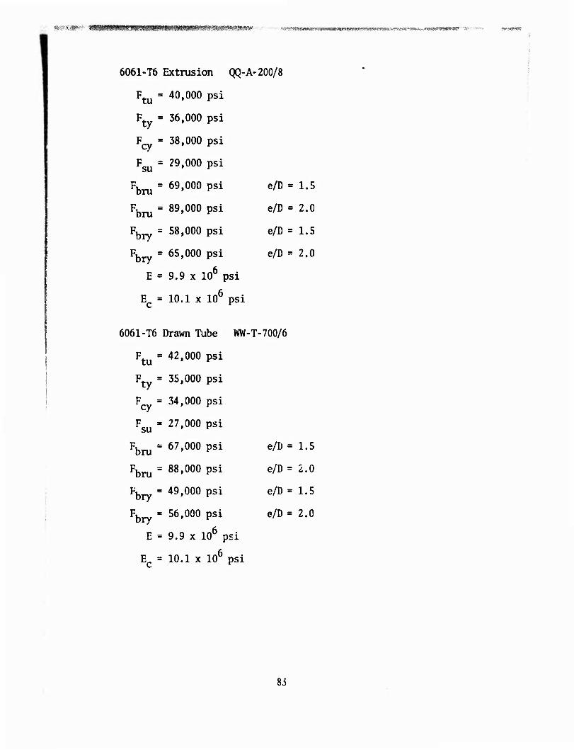
6061-T6 Extrusion QQ-A-200/8
Ftu = 40»000 Psi
Ft = 36,000 psi
F^ = 38,000 psi
Fsu = 29»000 Psi
Fbru = 69»000 Psi e/D = l'S
Fbru = 89»000 Psi e/D ' 2-0
Fbry = 58»000 Psi e/D s 1-5
Fbry != 65»000 Psi e/D a 2'0
E = 9.9 x 10⁶ psi
Ec = 10.1 x 10⁶ psi
6061-T6 Drawn Tube WW-T-700/6
Ftu = 42»000 Psi
Ft = 35,000 psi
Fcy = 34,000 psi
Fsu = 27,000 psi
Fbru = 67'000 Psi e/D = l's
Fbru = 88»000 Psi e/D = 2-0
Fbry = 49,000 psi e/D = 1.5
Fbry = 56'000 Psi e/D = 2-0
E = 9.9 x 10⁶ psi
Ec = 10.1 x 10⁶ psi
Si
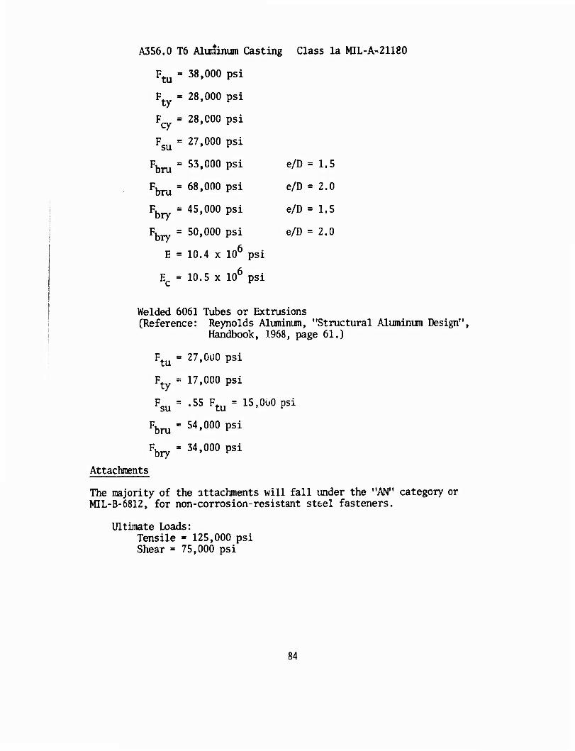
A356.0 T6 Aluminum Casting Class la MIL-A-21180
Ftu = 38»000 Psi
F = 28,000 psi
F^ = 28,000 psi
Fsu = 27'000 psi
Fbru = 53'000 Psi e/D = 1*5
Fbru = 68»000 Psi e/D ^ 2-0
Fb = 45,000 psi e/D = 1.5
Fbry = 50»000 Psi e/D = 2'0
E = 10.4 x 10⁶ psi
Ec = 10.5 x 10 psi
Welded 6061 Tubes or Extrusions (Reference: Reynolds Aluminum, "Structural Aluminum Design",
Handbook, 1968, page 61.)
Ftu = 27'0ü0 Psi
Ft = 17,000 psi
Fsu = •55 Ftu = 15'0u0 Psi
Fbru = 54'000 Psi
Fbry = 34'000 psi
Attachments
The majority of the attachments will fall under the "AN" category or MIL-B-6812, for non-corrosion-resistant steel fasteners.
Ultimate Loads: Tensile = 125,000 psi Shear = 75,000 psi
84
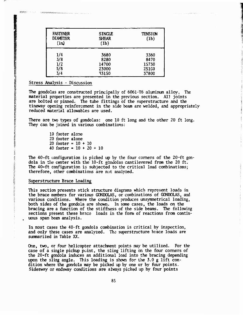
^^ÄF»-"' 'I«WW1SWW«>K««-
FASTENER SINGLE TENSION DIAMETER SHEAR (lb)
1 (in^ (lb)
1/4 3680 3360 3/8 8280 8470 1/2 14700 15730 5/8 23000 251C0 1 3/4 33150 37800 i
Stress Analysis - Discussion
The gondolas are constructed principally of 6061-T6 aluminum alloy. The material properties are presented in the previous section. All joints are bolted or pinned. The tube fittings of the superstructure and the tineway opening reinforcement in the side beam are welded, and appropriately reduced material allowables are used.
There are two types of gondolas: one 10 ft long and the other 20 ft long. They can be joined in various combinations;
10 footer alone 20 footer alone 20 footer =10+10 40 footer =10+20+10
The 40-ft configuration is picked up by the four comers of the 20-ft gon- dola in the center with the 10-ft gondolas cantilevered from the 20 ft. The 40-ft configuration is subjected to the critical load combinations; therefore, other combinations are not analyzed.
Superstructure Brace Loading
This section presents stick structure diagrams which represent loads in the brace members for various GONDOLAS, or combinations of GONDOLAS, and various conditions. Where the condition produces unsymmetrical loading, both sides of the gondola are shown. In some cases, the loads on the bracing are a function of the stiffness of the side beams. The following sections present these bncc loads in the form of reactions from contin- uous span beam analysis.
In most cases the 40-ft gondola combination is critical by inspection, and only these cases are analyzed. Tho superstructure brace loads are sumnarized in Table XX.
One, two, or four helicopter attachment points may be utilized. For the case of a single pickup point, the sling lifting on the four comers of the 20-ft gondola induces an additional load into the bracing depending upon the sling angle. This loading is shown for the 3.0 g lift con- dition where the gondola may be picked up by one or by four points. Sidesway or endsway conditions are always picked up by four points
85
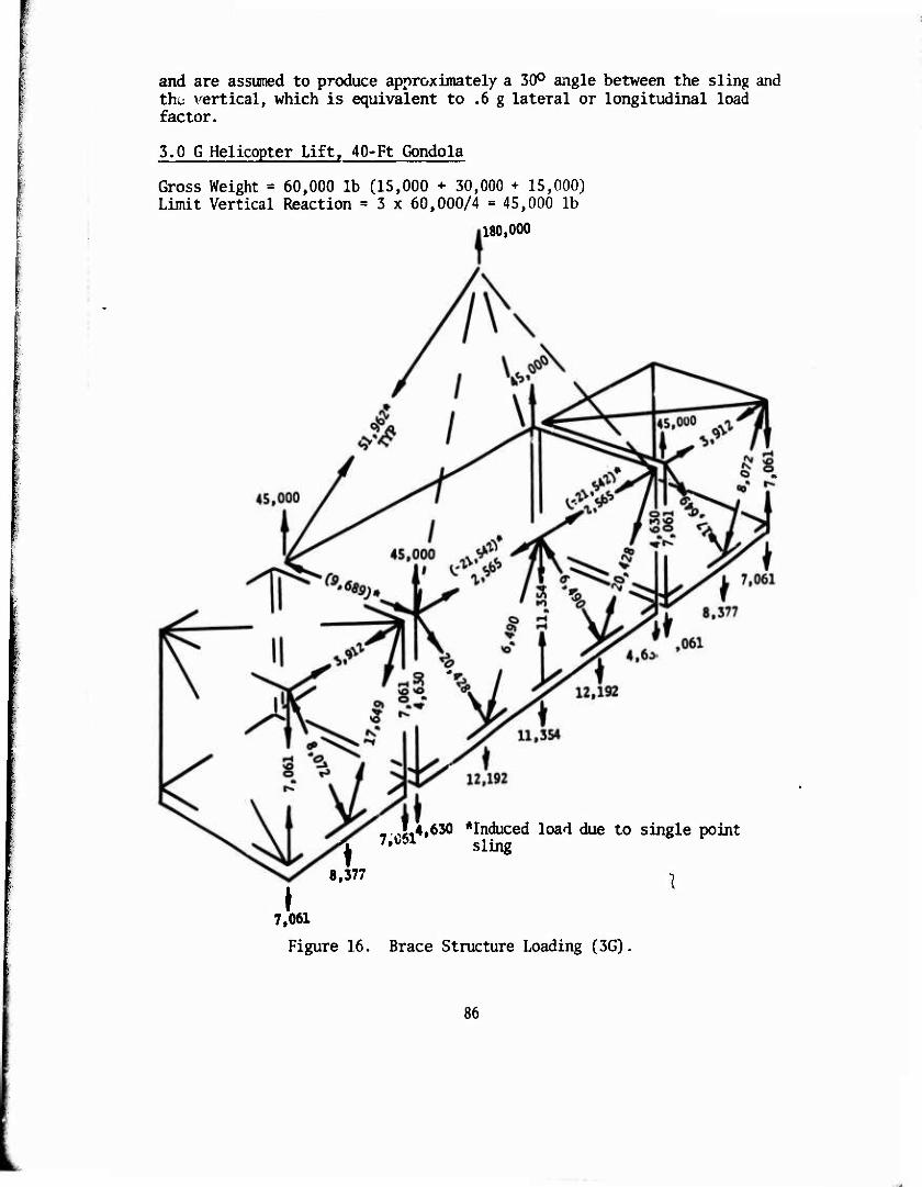
and are assumed to produce approximately a 30° angle between the sling and the vertical, which is equivalent to .6 g lateral or longitudinal load factor.
3.0 G Helicopter Lift, 40-Ft Gondola
Gross Weight = 60,000 lb (15,000 + 30,000 + 15,000) Limit Vertical Reaction = 3 x 60,000/4 = 45,000 lb
180,000
».4,630 *Induced load due to single point 'i 7,im sling
8,377 T
♦ 7,061
Figure 16. Brace Structure Loading (3G).
86
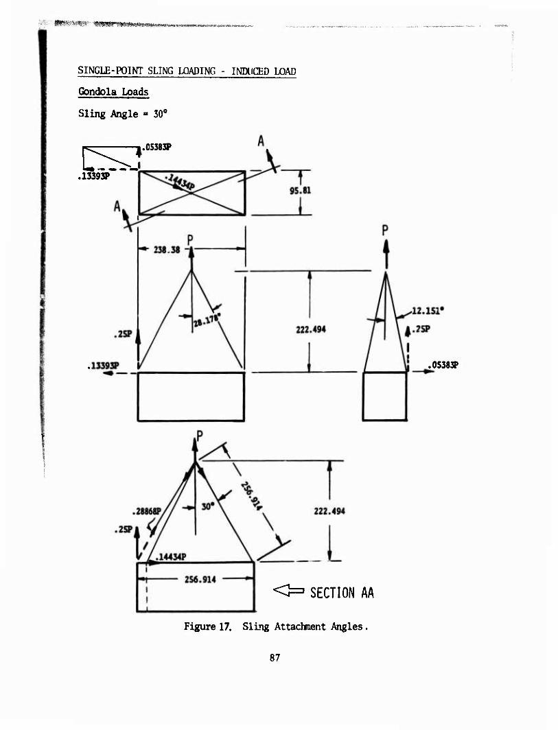
;■-. iff*-i«%5-- '^m**m'mt»imw' '^•«^\si»»-»'-W,ifir*K*.-.t,-;^v-vj'ff-.i*sBi>!'1«Bf«a**-^-»J
SINGLE-POINT SLING LOADING - INDUCED LOAD
Gondola Loads
Sling Angle « 30°
J.0S383P
.13393?"
<=■ SECTION AA
Figure 17. Sling Attachment Angles
.0S383P
87
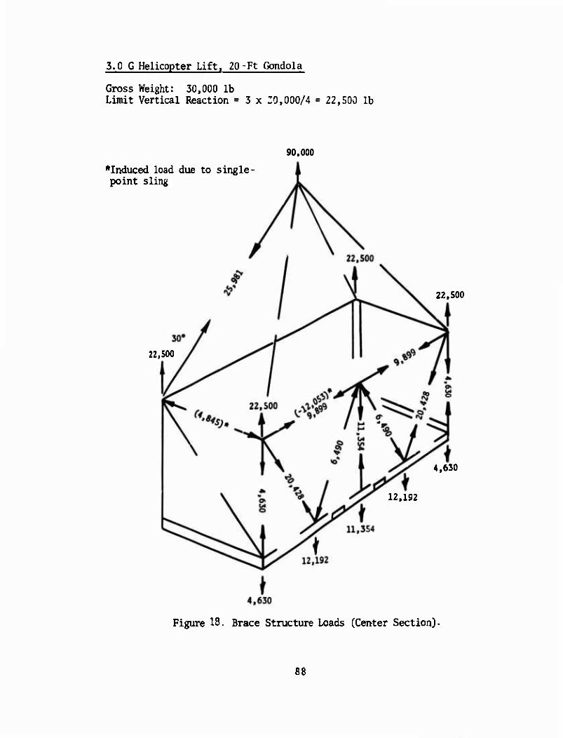
3.0 G Helicopter Lift. 20-Ft Gondola
Gross Weight: 30,000 lb Limit Vertical Reaction = 3 x 30,000/4 = 22,500 lb
90.000
*Induced load due to s ingle- point sling
22.500
22,500
4,630
12,192
Figure 18. Brace Structure Loads (Center Section).
88
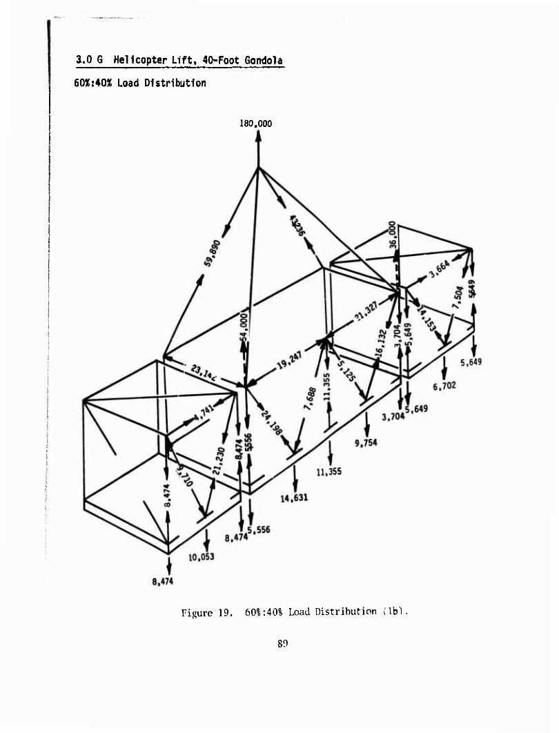
a.O G Helicopter Lift. 40-Foot Gondola
60%:AQ% Load Distribution
180,000
Figure 19. 601:40% Load Distribution i\h)
89
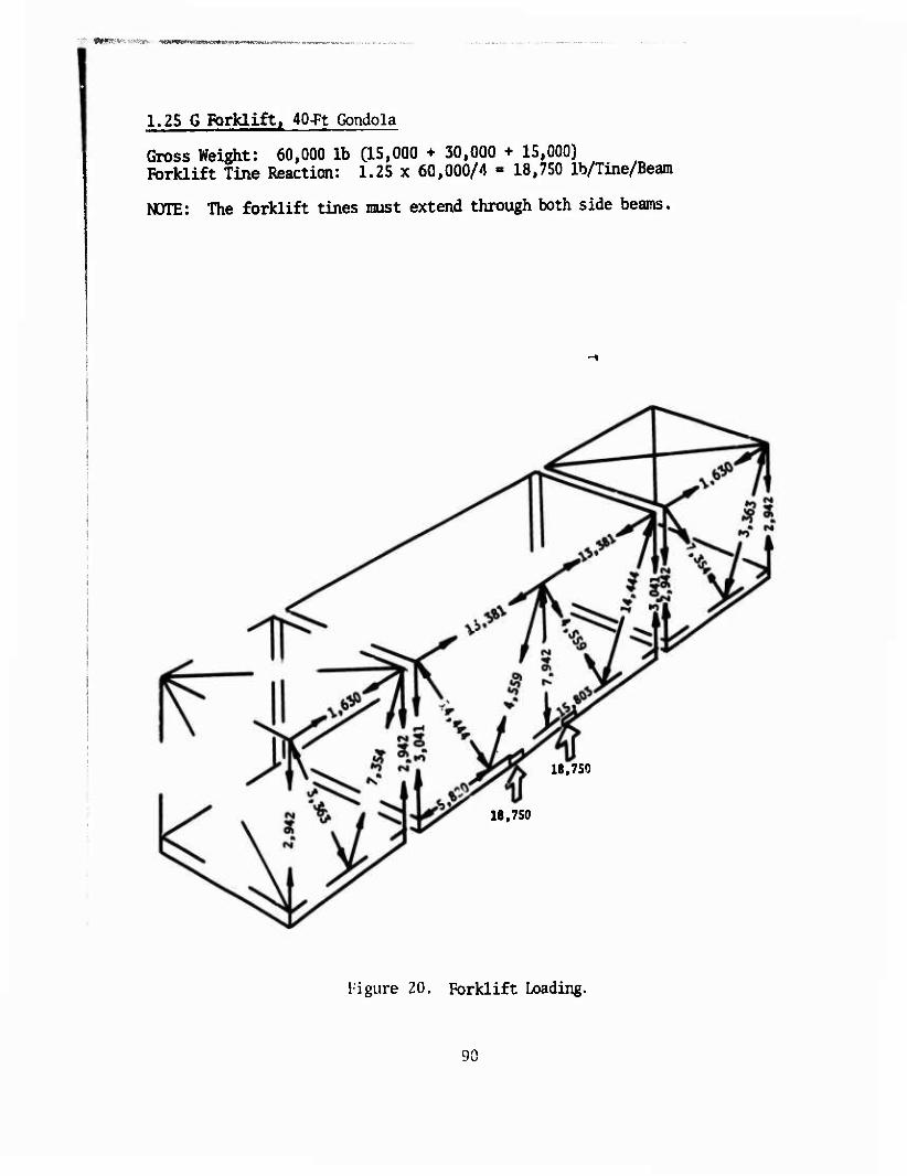
1.25 G Forklift. 40-Ft Gondola
Gross Weight: 60,000 lb CIS,000 + 30,000 + 15,000) Förklift Tine Reaction: 1.25 x 60,000/4 » 18,750 lb/Tine/Beam
NOTE: The forklift tines must extend through both side beams.
18,750
18,750
Figure 20. Forklift Loading.
90
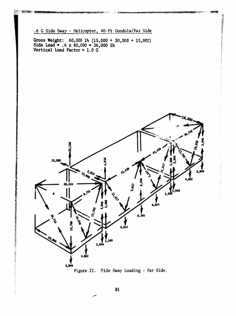
'8SlWi'WI«SIIHWWRsr«WR»e^^ f^jSPw»i»H«E!9w«<t«i»^^
■
.6 G Side Sway - Helicopter, 40-Ft Gondola/Far Side
Gross Weight: 60,000 lb (15,000 + 30,000 + 15,000) Side Load - .6 x 60,000 - 36,000 lb Vertical Load Factor »LOG
15,090
3.946
Figure 21. Side Sway Loading - Far Side.
91
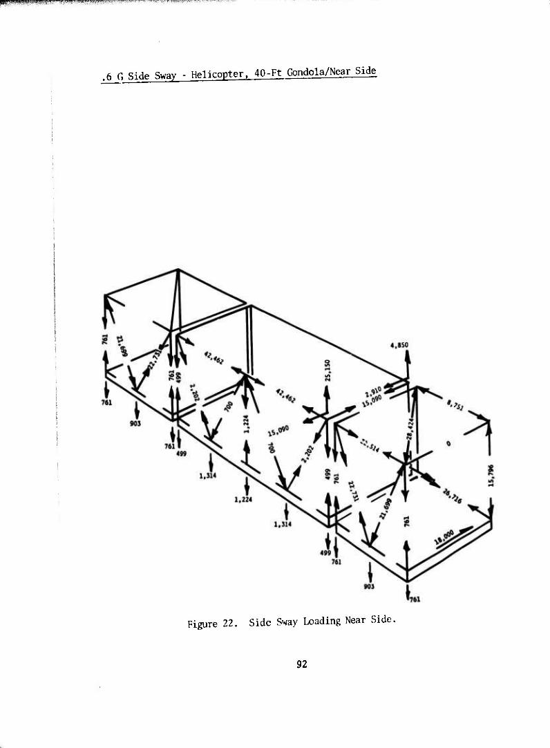
HSnpniPJ,! pump* i \'mv.^miiwm^¥MK-^^T^^--^r''^r^^!rf^F^^--^^^-^~\"^
.6 G Side Sway - Helicopter, 40-Ft Gondola/Near Side
Figure 22. Side Sway Loading Near Side.
92
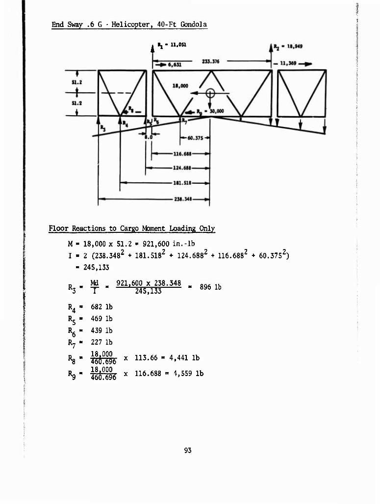
End Sway .6 G - Helicopter. 40-Ft Gondola
. Rj - 11,051
Floor Reactions to Cargo Moment Loading Only
M » 18,000 x 51.2 « 921,600 in.-lb I - 2 (238.3482 + 181.5182 + 124.6882 + 116.6882 + 60.3752)
• 245,133
D Md 921.600 x 238.348 _ fiQ, ,. R3 " T ' 245,133 896 lb
R4 = 682 lb R5 - 469 lb R6 - 439 lb R7 - 227 lb
*8 " *& X 113-66 " 4'441 lb
R9 " M& x 116-688 ' /l'559 lb
93
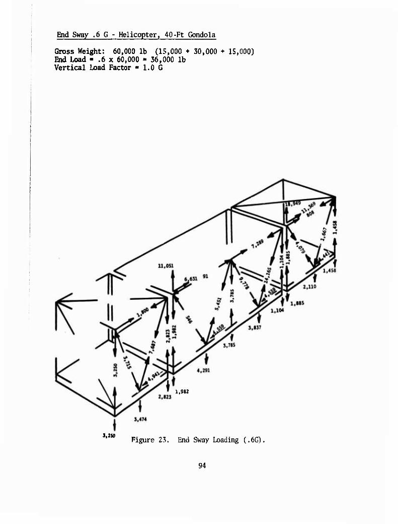
End Sway .6 G - Helicopter, 40-Ft Gondola
Gross Weight: 60,000 lb (15,000 + 30,000 + 15,000) End Load - .6 x 60,000 - 36,000 lb Vertical Load Factor - 1.0 G
1,982
S,2S0 Figure 23. End Sway Loading (.6G)
94
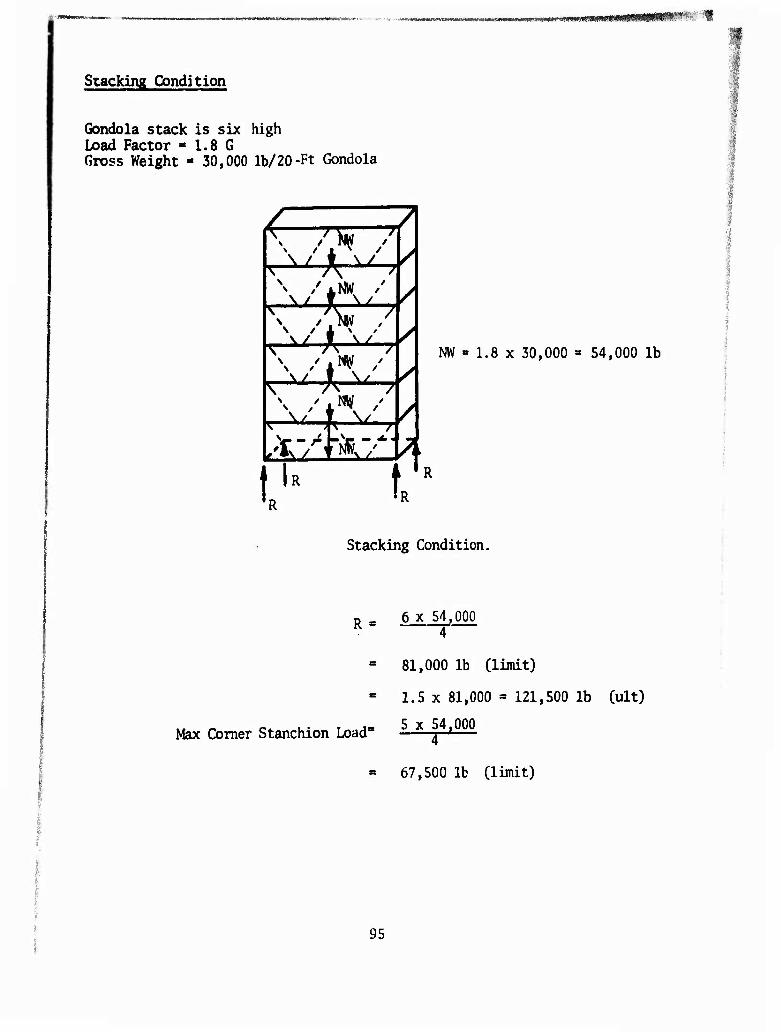
MMMn«wnuu*><'* ..-■■■-,■ .sij»^*«wiinf*rt»*i^x.««"^iviiw^A/^»^=Mfwiiwui*w^^
Stacking Condition
Gondola stack is six high Load Factor - 1.8 G Gross Weight - 30,000 lb/20-Ft Gondola
\ /> 7 /
v / ANW /' AX AX
ZNW , v / f v /
W / L
7
'v— A " / /
?
R t
NW « 1.8 x 30,000 = 54,000 lb
Stacking Condition.
R
Max Comer Stanchion Load"
6 x 54,000 4
81,000 lb (limit)
1.5 x 81,000 = 121,500 lb (ult)
5 x 54.000
67,500 lb (limit)
95
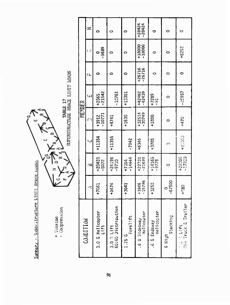
OJ
Z3 +J O
L. +-> n
vÜ O n
i
o
d
'*'* CM CM n: «S-'d-
o o o COCO CM CM + 1
o o o
oo o> oo OJ
( ) 00 oo in O W3 o o CO 00 o o OJ
1 i-H r-i + 1
CO +
lO VO f-t r-l
IJ_ O o o hs t^ o o o vo vo CM CM + 1
C\J t—» l-H CM <y\ r^ UJ in »i- VO CO vo ro en m
VD LO r». n ^- *r CO o en If) r-t CO ro CM CM CM i-H to
oc OJ CM r-t r-i «a- ^r r> en 0>J
cq + 1 1 + + i + i i
™^^—
»r LU r-t *»■ CTl s: CM f*. i-H o rH^t o
r-i t-H r-s. rT n m 1^ o o en o r>. io CM O OJ o r^ CO i-l ^t- t-H CO 00 .-H ^ + 1 + + + 1 + +
«d- Lf) fv"j LO in CM VO in i—
t_) CO CO »J- <■ CO o t—t i—i cr> ro r~. o 1 ~l <-H r-t r>. vo 00 CM
+ + i + + +
CO CO ^t r-i en LO to o CM CM en o «d- <* o-) en U3 00 o c J
•«3- r«* 1—< r—« m ^t r- vo t-Ht^ CM cn
ra o o «J- (^ c •> »3- CM rH VM~-, o oi r—
CM CO OJ cn r- rH CM CM i-< m CJ r--
+ 1 + i + 1 + i + i + 1
vo o t-< ■=>■ t-H vo en o o ^. W3 r^ ^t •vj- rv. in LO o * >* o M- O en Lfi CM o r^ CO r^ CO ro OO rH ro VO CO
+ + + + i + i +
i. c QJ o r—
L. •r* s_ s- •r-
OJ •M VU <u rc> 4J 3 *-> +J ■»-> rji i.
i g^ Q. a «4- >> a i.X CT h-
ö O ■r - ro o >, o •r-
U il t— 5 U (O o jk: c3 >—t ■r- 4-> +J 4-> J* (/i •<- 3: •<- ü ■»J
i— t— «»- <+- <S) t. QJ r-- </) i— (O *«- -V 0) T- *r- •r— o "O 1) "O <u -t > ••- o S 3C —I _J O i.u ■t- S c :n 00 _j n
C3 </) ÜJ ^= s- — CD £.'.> O nn ' • t- o M- in t3 e> •!-• <_i O o
O CM
vo VO -x.
- U',1 <vl 00 <X> t-< VO ; T'J
96
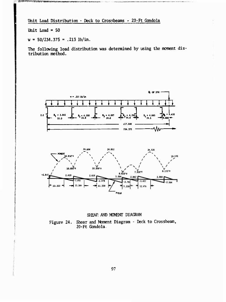
|SpW'W*W««w^|j(|gjg^ .
Ihit Load Distribution - Deck to Crossbeams " 20-Ft Gondola
Unit Load = 50
w = 50/234.375 » .213 lb/in.
The following load distribution was determined by using the moment dis- tribution method.
t OF SM
w ■ .21J lb/in
U M M I M M MT i i M M!! 2.0 R. > 2.142 f 1L.4.2M A «.- 4.197 1 R. • 4.2651 R. • 4.0IS 1% " 4»M
22.0 »T* »■» »T* M0 -^-*14.0 -i^- ^24.5 -^9.618"^
117.111
734.J75 ^kr
24.664 24.012 24.526
\ li.9J0"l / N / V 19.141
•2.142
1*13.522-1 -»I 11.586 \*- -#ju.
SEAR
SHEAR AND MOMENT DIAGRAM
Figure 24. Shear and Moment Diagram - Deck to Crossbeam, 20-Ft Gondola,
97
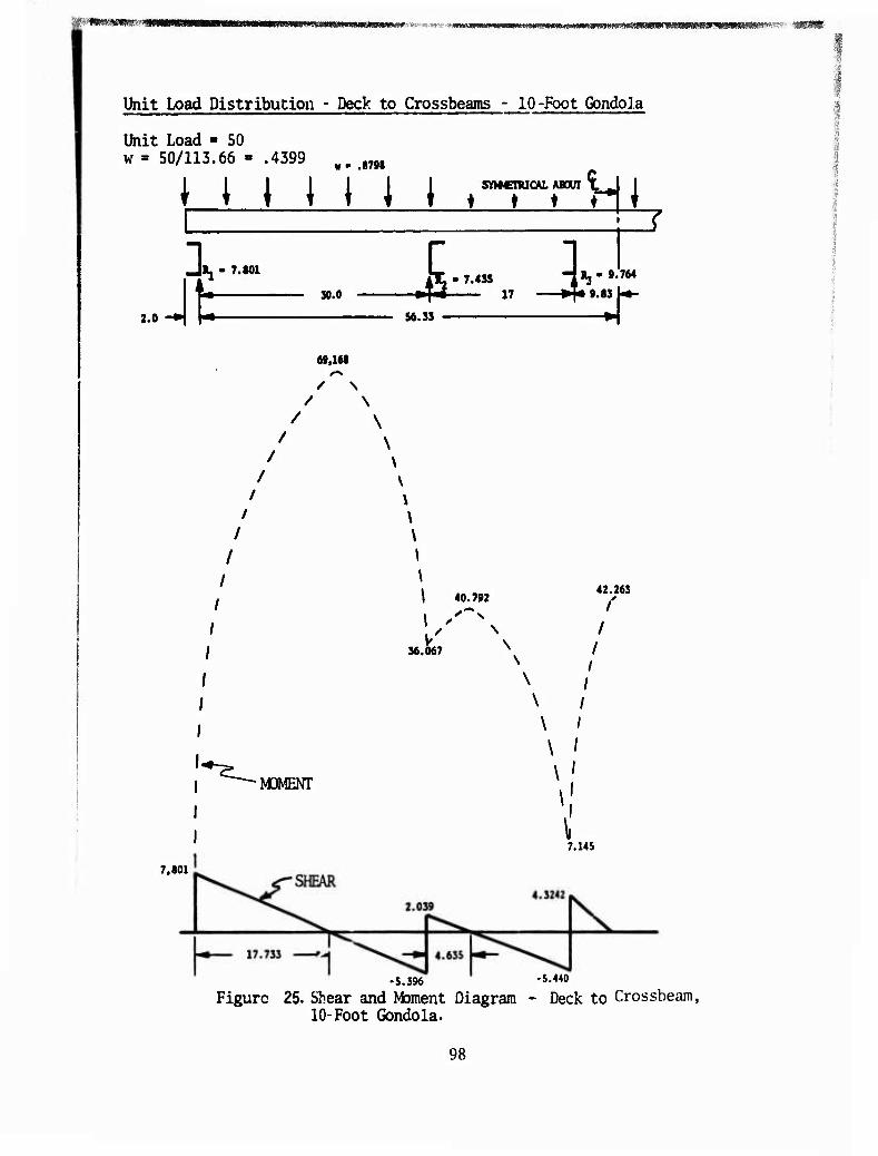
"■■f«W««l»""SB WBWIiaWWIMIWTOMtWWIIIIWIMMII^^ •««■a' *mmvmmvrm;m^^m^mmm^»'f'''' -«WB
Unit Load Distribution - Deck to Crossbeams - 10-Foot Gondola
Unit Load - 50 w = 50/113.66 - .4399 ¥m „n
i_i_L_Li_LJ t^^cHl
2.0 -*\ H—
7.801
1
30.0 -•44 17 *^* 9.83 U- S6.3S T
69,1«8
/ \ / \
/
\
\
\ 40.792
V 36.067
42.263 /'
/ /
I
•MOMENT
\ I
\ I
\ '
\ '
\ 7.14S
7,801
-5.396 -S.4«
Figure 25. Shear and Moment Diagram - Deck to Crossbeam, 10-Foot Gondola.
98
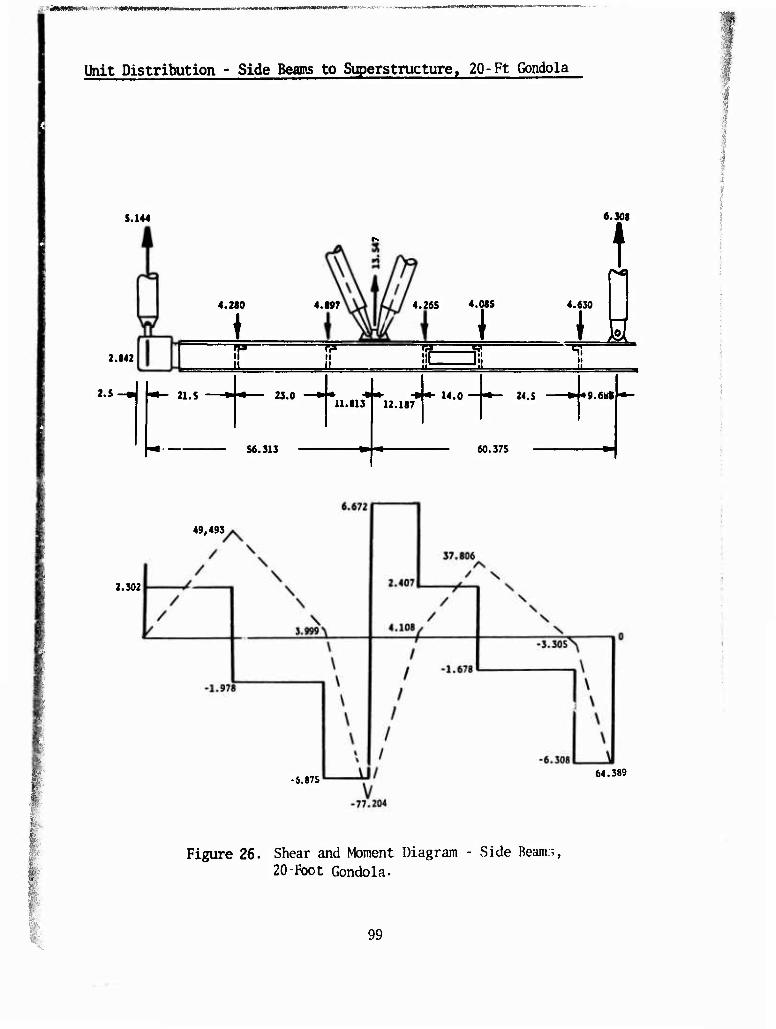
«»,.««-*W»WW>i*«'!«,»'W»W-'W»»«
Unit Distribution - Side Beams to Superstructure. 20-Ft Gondola
S.144
2.842
4.2S0
i na- il
2.5 21. S
4.S97 4.265 4.Q85
M
23.0
If P
6.308
t 4.630
I \ ■• •• -»I*- X4.o U 24.s —J-g.e««
il.813 12.187T j |
56.313 60.375
49,4P3
2.302
-8.87S 64.389
Figure 26. Shear and Moment Diagram - Side Beanie, 20-Foot Gondola.
99 ••:.
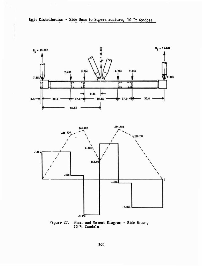
Unit Distribution - Side Beam to Supers ructure, 10-Ft Gondola
R, - 1S.692
256.750
7.891
-9.50«
Figure 27. Shear and Moment Diagram - Side Beams, 10-Ft Gondola.
100
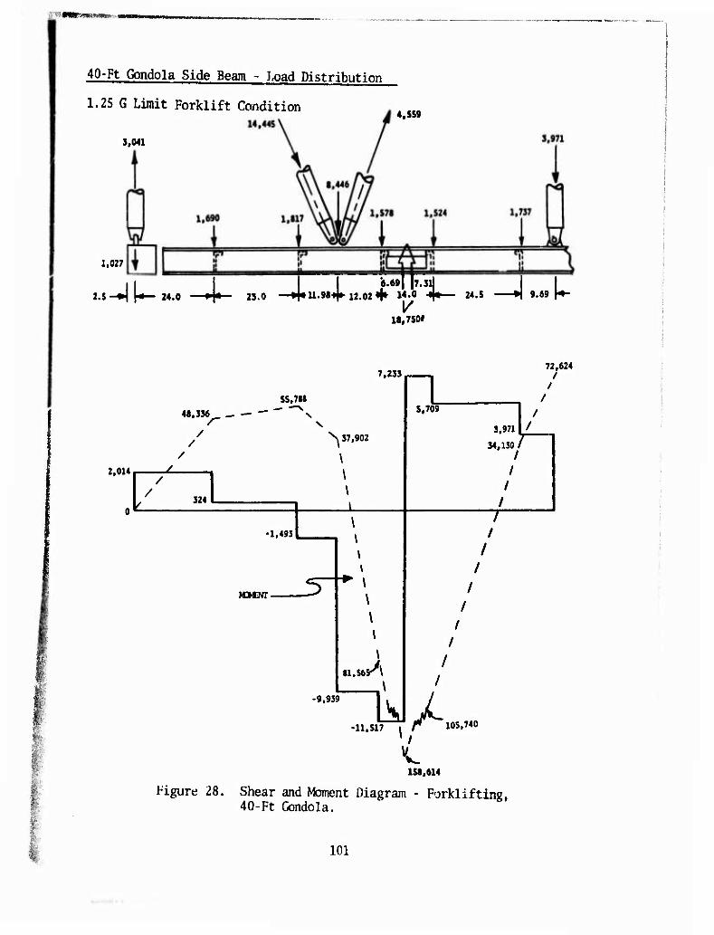
SMMMHMIMü »
40-Ft Gondola Side Beam - Load Distribution
1.25 G Limit Forklift Condition 4,SS9
3,041
1,027
2.S-H|-»— M.O —^|*- 2S.0 —-»^U.M«!»-12.02 «f M-« "V" M.5 A 9.69 W
18,7501
7,233
55,788
48,336 _ —
/ /
2,014 /
/ 324
-1,493
N 37,902
\ \ \ \
wmn-
\
\
81.56S<\
72,624 /
/
S,709
3,971
34,130 I I
I I
I T
■11.517 ^ r 105.740 /
158,614
Figure 28. Shear and Moment Diagram - Fork! if ting, 40-Ft Gondola.
101

y&m**am wni IIIWMIIWIIIIIIUJ
Side Beam Analysis
The 1.Z5 G limit forklift condition on the 40-ft-lün2 combined gondola set is the critical loading for side beam bending at the tineway cutouts.
x\
1.69
4.06 *
1.2S
"T U 13.0 H
Side Beam With Tineway
i
S.853
.S x 4.S0P1ATE
• 38
7 • .6414
Us ä« •5 -A I—.23
4. SO
»ra
.so
1.69
4.06
l.ZS
7.0
Upper Cap
A = 7.2063 in2, I = 3.66322 hi 7= 1.02516 in
Lower Cap
A = 4.4151 in2
i= .71307 in^ Z = .6414 in
7 x 4.5 "I" BEAM
.5 ANGLE 4 PUCES
Section Through Tineway Reinforcement
Figure 29. Tineway Analysis.
102
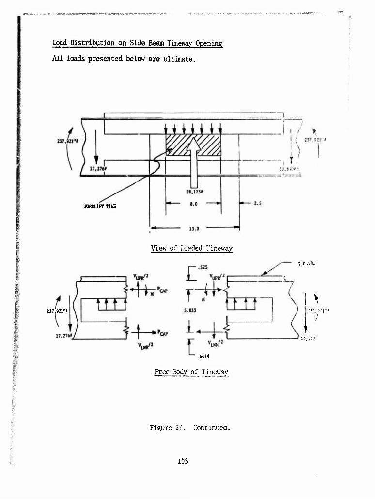
-vWU>Ji'.WIWWW« Wiymwwjwtieaiwuw^tn* ■ jitj«www«»wiiai*iwi>iwww' ■ ■■ ' "
Load Distribution on Side Beam Tineway Opening
All loads presented below are ultimate.
I i
PORKLIFT TINE
237,921"l
View of Loaded Tineway
.6414
Free Body of Tineway
S PtATE
I
10,850
Figure 29. Continued.
103
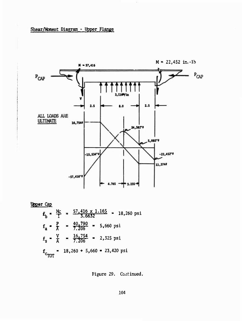
Shear/Moment Diagram - Upper Flange
M » S7.416 M = 22,452 in.-lb
rCAP
Upper Cap r Mc 57.416 x 1.165 , lft ^n _c4 £b" T = '3.6632 18,260 psi
£. - 40.790 5,660 psi ■a * " Tm . V 16.754 . 7 „r • fs- Ä B 7^06" " 2'325PS1
f - 18,260 + 5,660 - 23,420 psi cTOT
Figure 29. Continued.
104
PCAP ' 237.921/5.833 - 40,789 lb
VUPR + VLWR ' 17'276 * 10'850 " 6'426 lb
VLWR " ^.6632271^0!71307) x 6'427 " W*7 lb
VUPR 6'426' 1»047 = 5'379 lb
PCAP " 237.921/5.833 = 40,790 lb
Fixed End Moment at Edge of Cutout
1) Due to Tine Load:
M« - i £ (C2 - 3L2)
C « 8 in. L = 13in.
W = 28,125 lb
W s h X 2&l\25 ^S2 " 3 x u2) " "39,934 in.-lb
2) Due to Beam Shear:
M' - ^^2) x 6.5 = 5,379 x 6.5/2 * 17,482 in.-lb
MJ^J, - -39,934 - 17,482 •= -57,416 in.-lb
-or-
Mj^, - -39,934 + 17,482 » -22,452 in.-lb
105
.^vrÄ^^v-Ww^^f^-^WT^S^'1''
tu
SU
R.
M.S. = -
27,000 psi
15,000 psi 1 23.920
- .886
2.325 islööff = .155
1
[Rc2 + V Jjl/2
WELD ALLOWABLES OF 6061-T6
1 = .886 -f*-.15T - 1 - .11
Lower Cap
Mament at Edge of Cutout
M » CVLWR/2) x 6.5 = 1,047 x 6.5/2 = 3,403 in.-lb
f . Mc - 3.403 x .6414 _ , nftn „c. fb' T ' .71307 3,060 psi
ft ' Ä " ABT = 9'239 Psi
L ' 9,239 + 3,060 * 12,299 psi
t" » 1.047 s i ' itnsr s 237Psi
1.2 M « _ 27.000 T _
Column Analysis
Column analysis is performed on all braces. The critical column load is taken from the Sunmary - Siyerstructure Limit Brace Loads. For all brace members whose L'/P is greater than TT [2E/F ]l/^, Eulers Column formula
is used; for values greater, Johnsons's column formula is used. The ma- terial for all members is 6061-T6 drawn tubing.
F is the same as F = 34,000 psi
Er = 1Ü.1 x 106 psi
106
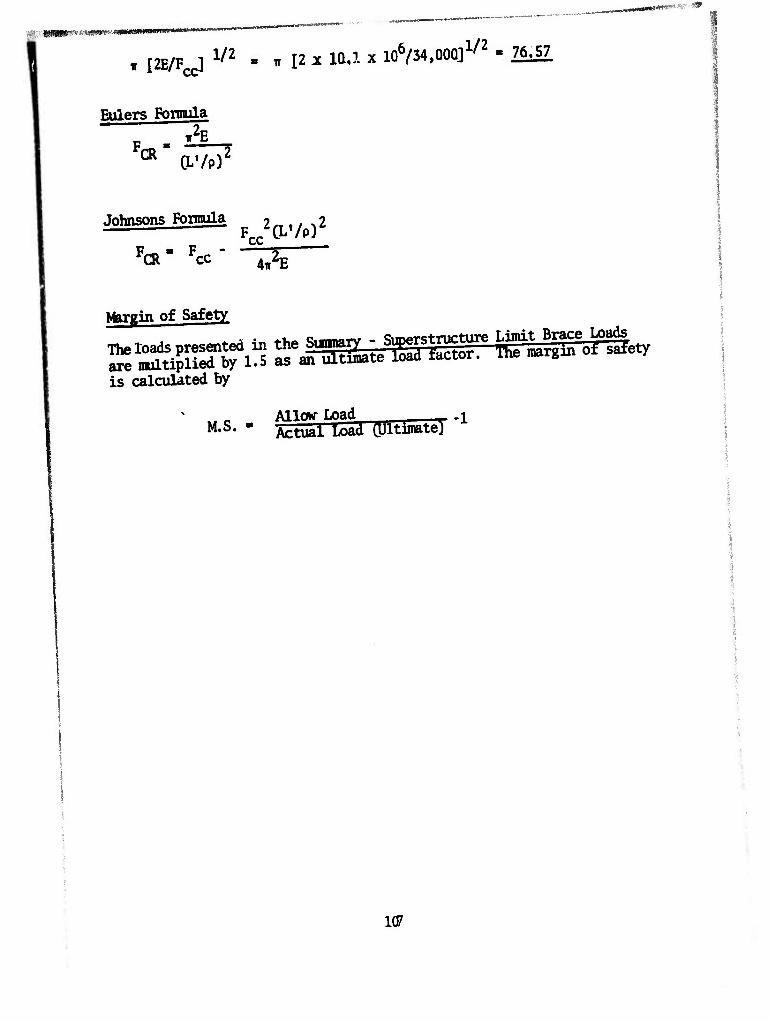
mmmm ^mt/mtmimmmm^
IT I2E/FCC] V2 m ill* la.l x 106/34.00Q]1/2 - 76^57
t.
Eulers Fonrula
01 O-'/P)2
Johnsons Fonnula
FCR" Fcc-
F^CLVP)
4Tt2E
Nbr^in of Safety
The loads presented in the Sunnary - Superstructure Limit Brace Loads are multiplied by 1.5 as an ultimate load factor. The margin of safety
is calculated by
w c . Allour Load , M-J>* Actual Load ÖJitimate) "1
107
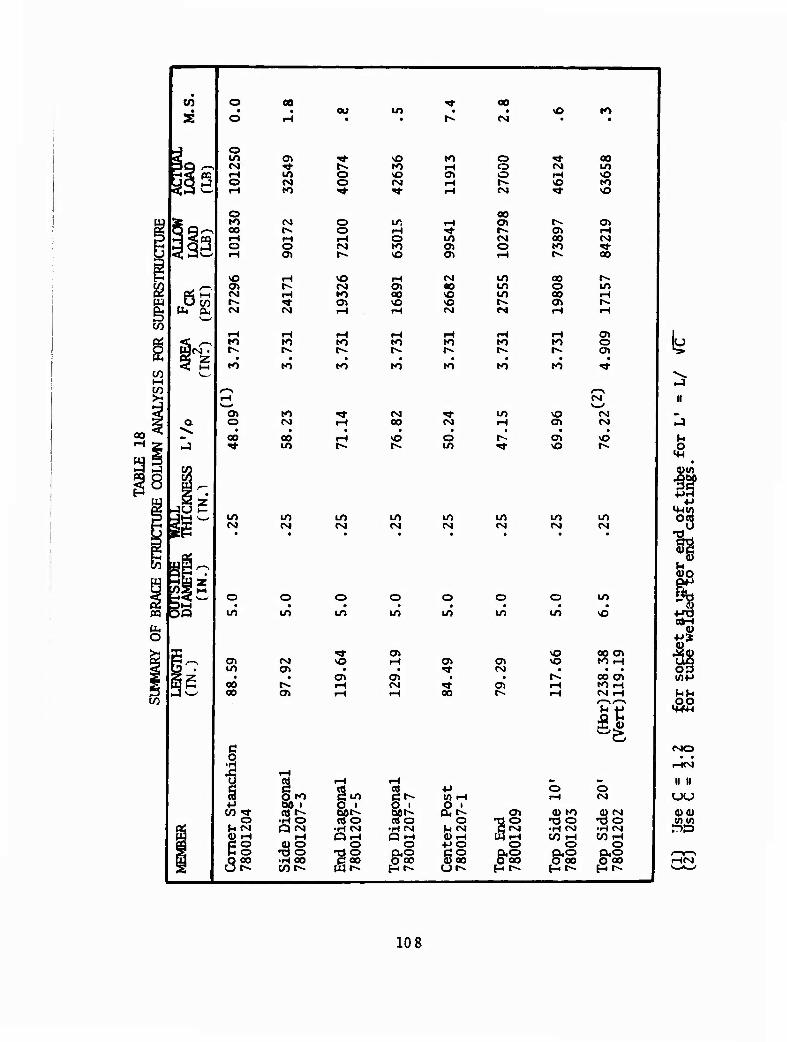
to o
o a> m
ao »O
/IS?
PQ
o
o ro oo
CM
to
»o
o
00
CM
o
00 00
a*
«M
fM
o
(M
ro
»o
lO CM
00
(M
O
CM
O o 'S-
o o
CM
IO
to
to iH NO O» CM iH ^t rH
LT, r-t rH TJ- O lO to Oi vO C7>
iH CM cn 00 CO VO vO VO iH CM
to rH to
1^ t^
to
o lO
vO
to
00
vO
in CM
c o •H
1 »H
QtO <-» bO i Ö * w »* rt t^ bO»^ o •rtO ctf O J*CM Q CM ■H CM « iH iH Qr-(
e§ 0)0 O •do •T3 O
8S •HOO CQ0 t2 r^ cnt--
«3 o i «J O
•H CM
O oo
to
CM
o to
lO CM
o O • • lO lO
o> iH o> • «* o> • CM 'S- iH oo
o o o CM
00
CM O
LO lO lO
CM
to
to
in
in CM
o in
CM
a\
CM
oo to
oo o oo
to
to
vO o^
vO
m CM
•p 1/1 t-l p ' a. «^ o H CM (UfH 4JO ÖO 0) 00
TJ O
IS O
&i
0) to TS O •H CM C/3 tH
O
&§
00 m vO to vO
rH CM ■«* 00
m
cn o cn
CM
CM CM
vO
in CM
o m • • in vO
s ao ai tO r-i • • •
iH
ao o> •O r-i CM rH /—\i—v
o (M
Q> CM •Ö O •H CM C/3 rH
O 0,0 5^00
II
V4
ß
, 4J
og
PS
03 tfip
.0,0
CMO • *
i-KM
II II UU 4)4) torn ro
i-HCM
10 8
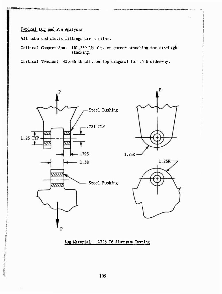
■ ■
Typical Lug and Pin Analysis
All uibe end clevis fittings are similar.
Critical Compression: 101,250 lb ult. on comer stanchion for äix-high stacking.
Critical Tension: 42,636 lb ult. on top diagonal for .6 G sidesway.
Steel Bushing
781 TYP
1.25R
Steel Bushing
Lug Material: A356-T6 Aluminum Casting
109
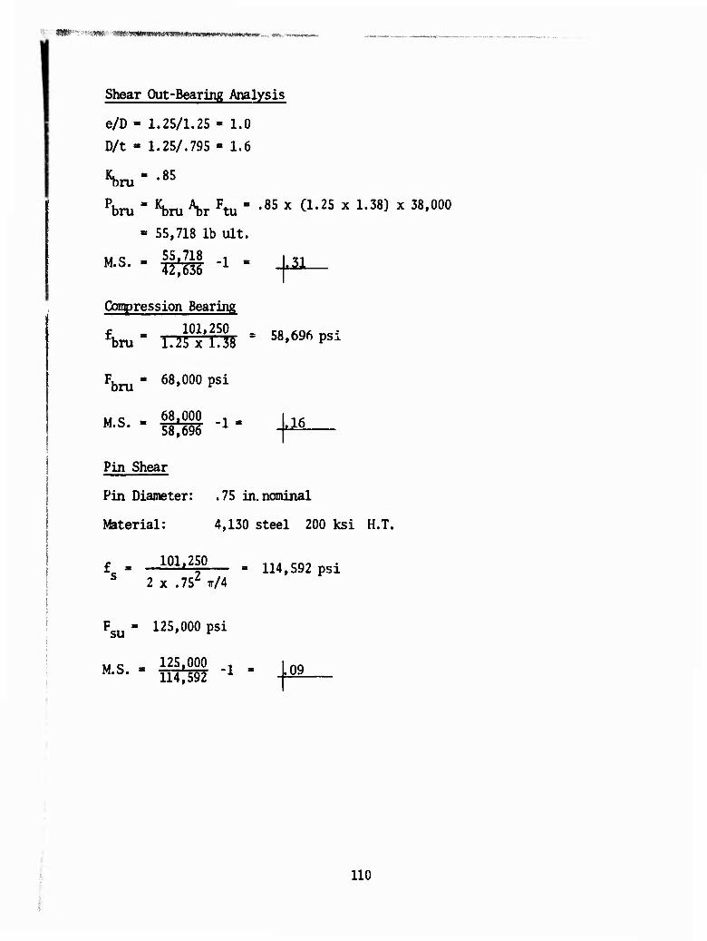
MS»-";"<"<.«».•■■ ■mfä'3m>mmA-im*mmm*vmv^wanm«*im... <m~<**a~**m*
Shear Out-Bearing Analysis
e/D - 1.25/1.25 » 1.0
D/t - 1.25/.795 - 1.6
«bru " •85
Pbru = Kbru V Ftu ' -8S x Ö.25 x 1.38) x 38.000
» 55,718 lb ult.
Compression Bearing
f 101,250 _ rfl .Qft - fbrua 1.25x1.38 = 58,6% ps.
Fbru " 68'000 psi
w c 68,000 , M-S* 5M^ ^ .16
Pin Shear
Pin Diameter: .75 in. nominal
Material: 4,130 steel 200 ksi H.T.
f » 101.250 S 2 x .752 ir/4
Fsu = 125,000 psi
114,592 psi
MS - 125'000 -l » L09 M•i,• 114,592 1 J^9
110
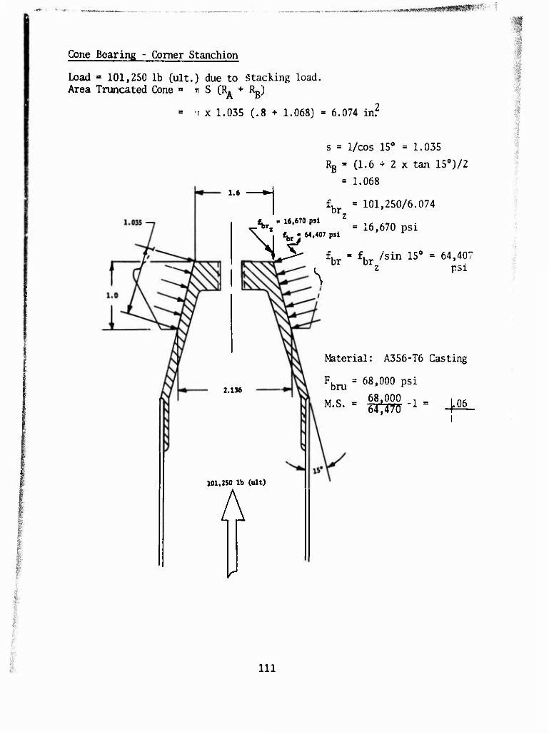
.^i.TÄ'c'twv«-; «MMBMMR tm I
Cone Bearing - Comer Stanchion
Load » 101,250 lb (ult.) due to Stacking load. Area Truncated Cone ■ TT S (R. + Rg)
= r x 1.035 (.8 + 1.068) = 6.074 in.2
s = 1/cos 15° = 1.035
RB = (1.6 + 2 x tan 150)/2
= 1.068
fbr = 101,250/6.074 t - 16,670 psl Z
^-^«■i = 16,670 psi \ | «bryM.407p$i
l^S- fbr = fbr /sin 15° = 64,40: L z psi
1.6 »-I
2.136
101,250 lb (ult)
A
Material: A356-T6 Casting
Fbru " 68'000 psi
x, c 68,000 T . n.
\r
in
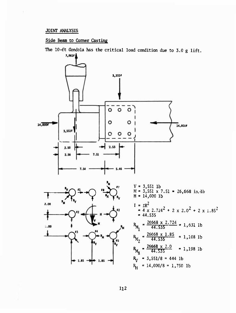
JOINT ANALYSIS
Side Beam to Comer Casting
The 10-ft Gondola has the critical load condition due to 3.0 g lift. 7.061li
14.0001
s.ssn
14,000f
2.00 "
V » 3,551 lb M » 3,551 x 7.51 - 26,668 in.-lb H = 14,000 lb
I = IR^ = 4 x 2.7242 + 2 x 2.02 + 2 x i.852
= 44.535
D = 26668 x 2.724 , ,T1 1U \-—4—33 1'6311b
o „ 26668 x 1.85 , . infl ,. ^ 44.535 l*m lb
P . 26668 x 2.0 _ , 1Q0 1k \ 44.535— -1.198 1b
Ry = 3,551/8 = 444 lb
R^, = 14,000/8 = 1,750 lb
112
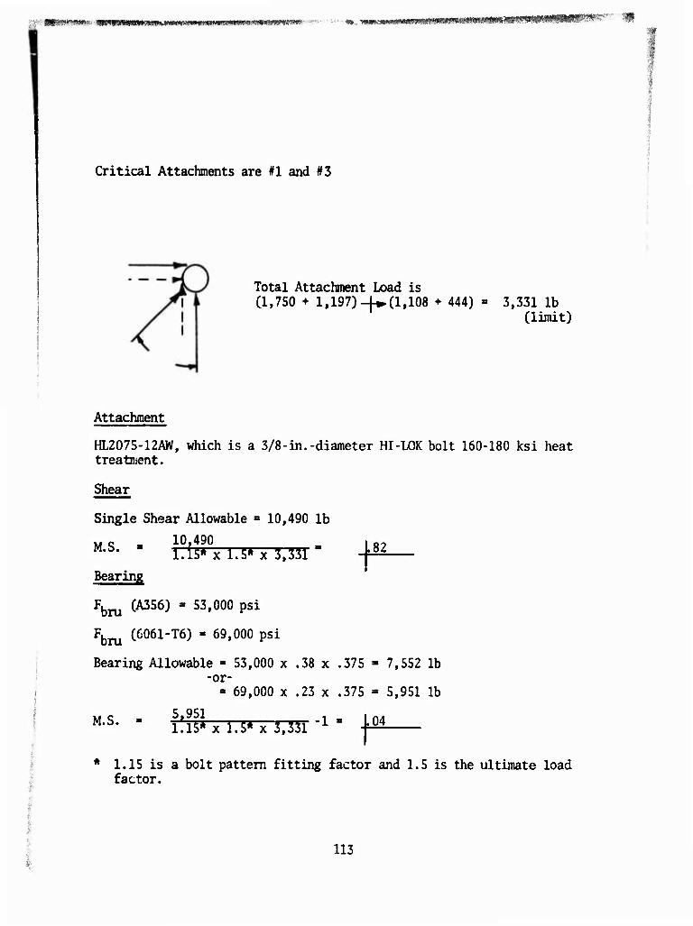
■: ■ imew*™*- ■ ■wmmmmmma&mmmmmmmmmmmmm*mmm• --■ ■•■■■■*». T>^wv'P'm^mi*mm»tfmH0*m' Sir m
Critical Attachments are #1 and #3
Total Attachment Load is Cl, 750 + 1,197)-[♦(1,108 + 444) 3,331 lb
(limit)
Attachment
HL2075-12AW, which is a 3/8-in.-diameter HI-LOK bolt 160-180 ksi heat treatment.
Shear
82
Single Shear Allowable ■ 10,490 lb
Mc . 10,490 m M-S- l.is*x 1.5* x 3,331
Bearing
Fbru CA356) " 53'000 Psi
Fbru C6061"T6) " 69'000 Psi
Bearing Allowable » 53,000 x .38 x .375 - 7,552 lb -or-
» 69,000 x .23 x .375 » 5,951 lb
M.S. 5,951 i:iS*x 1.5* x 3,331 ^ ' + 04
* 1.15 is a bolt pattern fitting factor and 1.5 is the ultimate load factor.
113
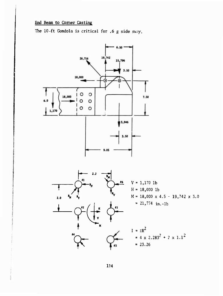
End Beam to Comer Casting
The 10-ft Gondola is critical for .6 g side sw;iy,
2.0 ^ ^
V = 1,170 lb
H = 18,000 lb
M = 18,000 x 4.5 - 19,742 x 3.0 s 21,774 in.-lb
I = zr - 4 x 2.2832 + 2 x l.l2
= 23.26
114
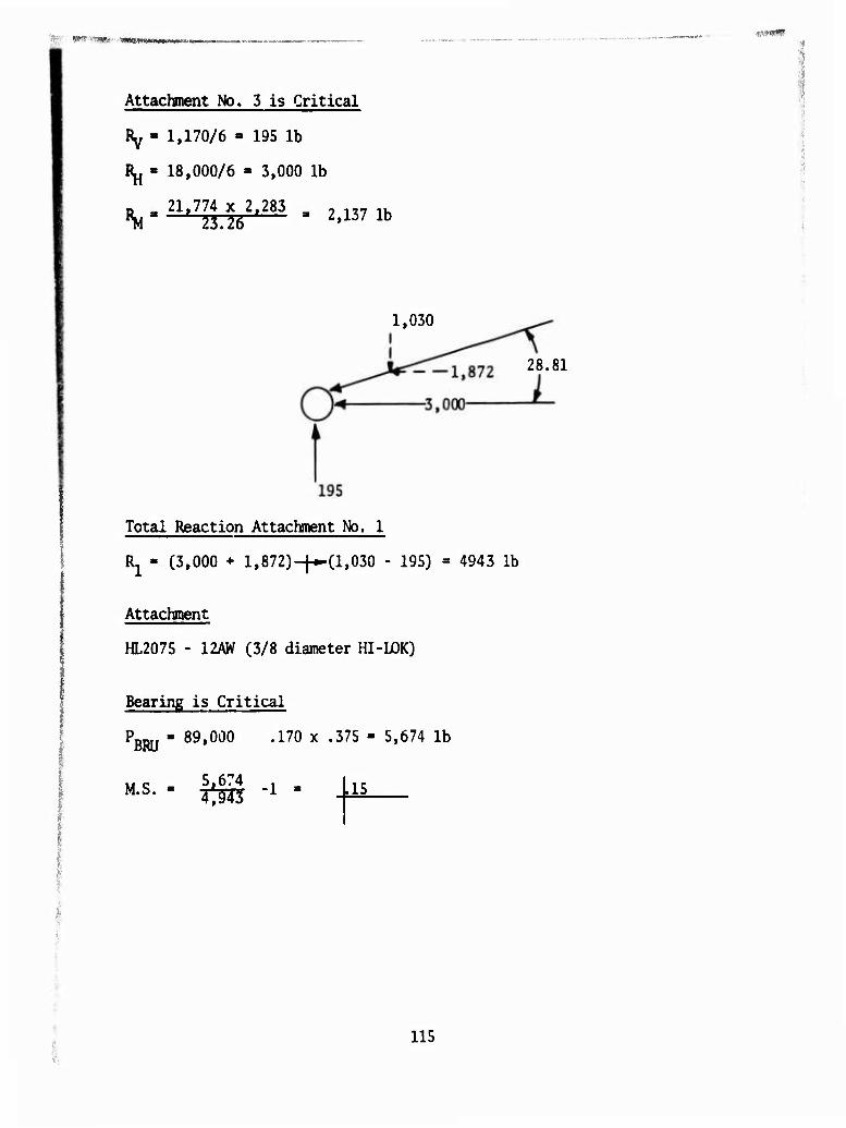
■wirwn
Attachment No. 3 is Critical
Ry - 1,170/6 - 195 lb
1^ - 18,000/6 - 3,000 lb
D « 21.774 x 2,283 3 , ,„ ,. ^ 2i.l6 '— 2'137 lb
1,030
Total Reaction Attachment No. 1
Rj - C3,000 + 1,872)-|^(1,030 - 195) = 4943
Attachment
HL2075 - 12AW (3/8 diameter HI-LOK)
28.81
lb
Bearing is Critical
PBRU * 89»000 •170 x •375 " 5»674 lb
M.S. 5.674 , 1^3 1 15
115

M54. 5-Ton Truck Loaded on 40-Ft Gondola With M149 2-Wheel Trailer
Weight Distribution - loaded (Ref MS53087 § 500024)*
Curb Weight
Pay Load
Tire Loading
Trailer
Tire Loading
Design Loads:
Front Tire = 4750 x 3.0 = 14,250 lb
FRONT AXLE (LB)
INNER AXLE (LB)
REAR AXLE (LB)
TOTAL (LB)
3735 5605 5605 19,945
765 9617 9617 20,000
9500 15300 15300 40,100
- - 5455 5,455
limit (21,375 lb ult.)
Inter § Rear Tires = 3825 x 3.0 = 11,475 lb limit (17,212 lb ult.)
Trailer Tires = 2728 x 3.0 = 8,184 lb limit (12,275 lb ult.)
Wheel base, truck, 179 inches
Tread - Front Axle 74 in. Inter 5 Rear Axle 72 in. Trailer Axle 67-3/8 in.
Tire Area 9 in. wide-x-10 in. long
Since trailer axle loads are significantly lower than truck axle loads, they are not analyzed for floor loads.
Cieck Deck Grating
The front tire produces the critical pressure load on the deck. The max- imum span between crossbeams is 30 in. but contains intermediate bracing. Therefore, the critical span is 24.5 in.
* Heaviest Vehicle in Table 2
116
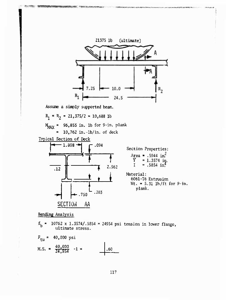
ÄStÄSte- '!%*!$!mmmm*mmtmmmK. ^msy^mtmimm ■■■•■ - ■- - MM»WI«K»'«i'-.w"ct Mm ^s-V»M IWMMWi -. ^.IIM ■.*-.- r..' -.r\f ■■' '.»:»■ Mf -»■..■ -»'■"uÄ»"!»
21375 lb (ultimate)
Assume a simply supported beam.
^ = 112 = 21,375/2 = 10,688 lb
I^j^ = 96,855 in. lb for 9-in. plank
= 10,762 in.-lb/in. of deck
Typical Section of Deck I-*—1.808-H r .094
.12
d
1
i
Al I 1 2.562
Section Properties;
Area ■ .5944 in.2
Y » 1.5574 in. I = .5854 in?
1 .750
SECTION AA
.203
Material: 6061-T6 Extrusion Wt. »5.31 lb/ft for 9-in.
plank.
Bending Analysis
£b = 10762 x 1.3574/.5854 = 24954 psi tension in lower flange, ultimate stress.
Ftu a 40»000 Psi
M c 40,000 , .60
117
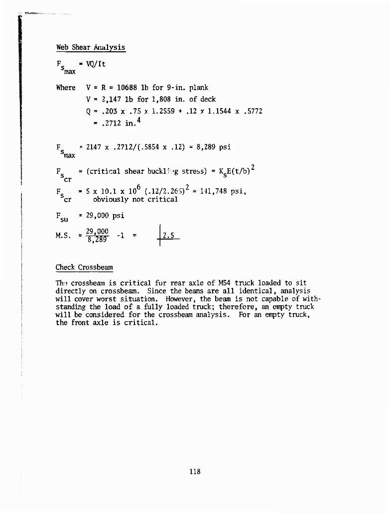
Web Shear Analysis
F = VQ/It max
Where V = R = 10688 lb for 9-in. plank
V = 2,147 lb for 1,808 in. of deck
Q = .203 x .75 x 1.2559 + .12 y 1.1544 x .5772
= .2712 in.4
2147 x .2712/(.5854 x .12) = 8,289 psi max
F = (critical shear buckll 'g stress) = K E(t/b) cr
F = 5 x 10.1 x 106 (.12/2.261i)2 = 141,748 psi, cr obviously not critical
Fsu = 29,000 psi
M c 29,000 -1 = 2.5
Check Crossbeam
Tho crossbeam is critical for rear axle of M54 truck loaded to sit directly on crossbeam. Since the beams are all identical, analysis will cover worst situation. However, the beam is not capable of with- standing the load of a fully loaded truck; therefore, an empty truck will be considered for the crossbeam analysis. For an empty truck, the front axle is critical.
118
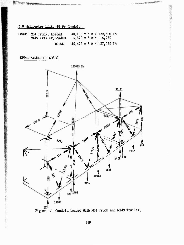
.,-,-. wwwfciia^jiWiiLTIWni
3.0 Helicopter Lift, 40-Ft Gondola
Load: M54 Truck, Loaded 40,100 x 3.0 = 120,300 lb M149 Trailer, Loaded 5.575 x 3.0 = 16,725
TOTAL 45,675 x 3.0 = 137,025 lb
a
i
UPPER STRUCTURE LOADS
&■
30181
^ S ^ ^ A" ^>- 1 9841
880
1408
♦ 9848
29018
9848
Figure 30. Gondola Loaded With M54 Truck and M149 Trailer.
119
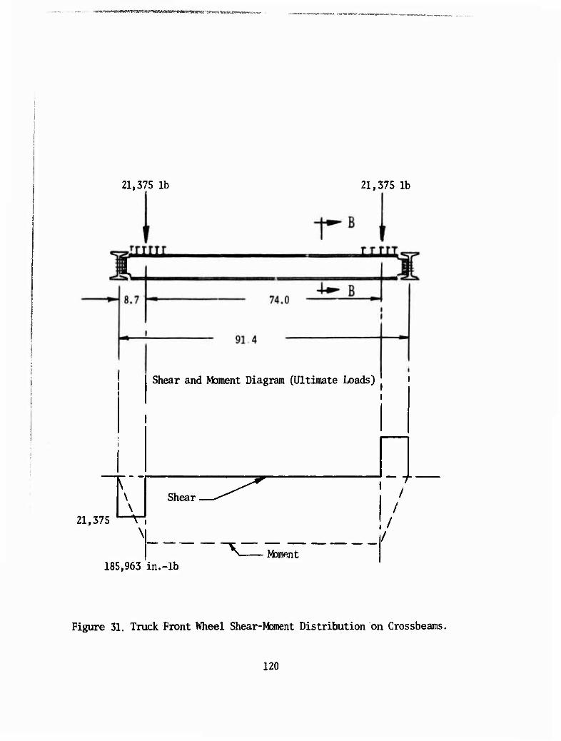
rVHM *'V3VT J?f««,tw»nws- .-•*■
21,375 lb 21,375 lb
Shear and Moment Diagram (Ultimate Loads) '
Shear
21,375 '—V-* \
I I
I
Mament 185,963 in.-lb
/
Figure 31. Truck Front Wheel Shear-Moment Distribution on Crossbeams.
120
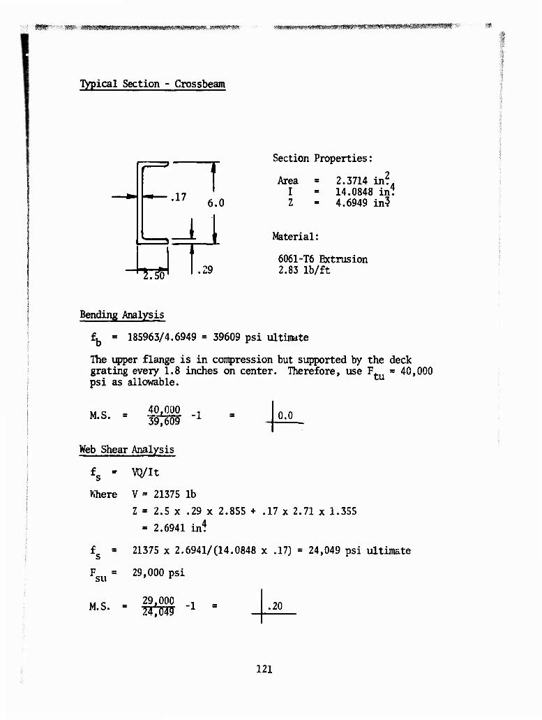
M ■ WP"';'!'*P- -imwmmfmw^mvmmmvi^mm» s*mw*m: ^MWBIMIWMIIWMIIWBimillMWWIt^^ s: ft«
Typical Section - Crossbeam
.17 6.0
M T^ .29
Section Properties:
Area I Z
Material:
2.3714 inf. 14.0848 in. 4.6949 in?
6061-T6 Extrusion 2.83 lb/£t
Bending Analysis
fb = 185963/4.6949 » 39609 psi ultimate
The upper flange is in compression but supported by the deck grating every 1.8 inches on center. Therefore, use F^, * 40,000 psi as allowable. tu
M.S. 40,000 T 39,609 'l 0.0
Web Shear Analysis
£s - VQ/It
Where V = 21375 lb
Z = 2.5 x .29 x 2.855 + .17 x 2.71 x 1.355
» 2.6941 in*
£s = 21375 x 2.6941/(14.0848 x .17) = 24,049 psi ultimate
Fsu " 29'000 psi
M.S. = 29.000 .20
121
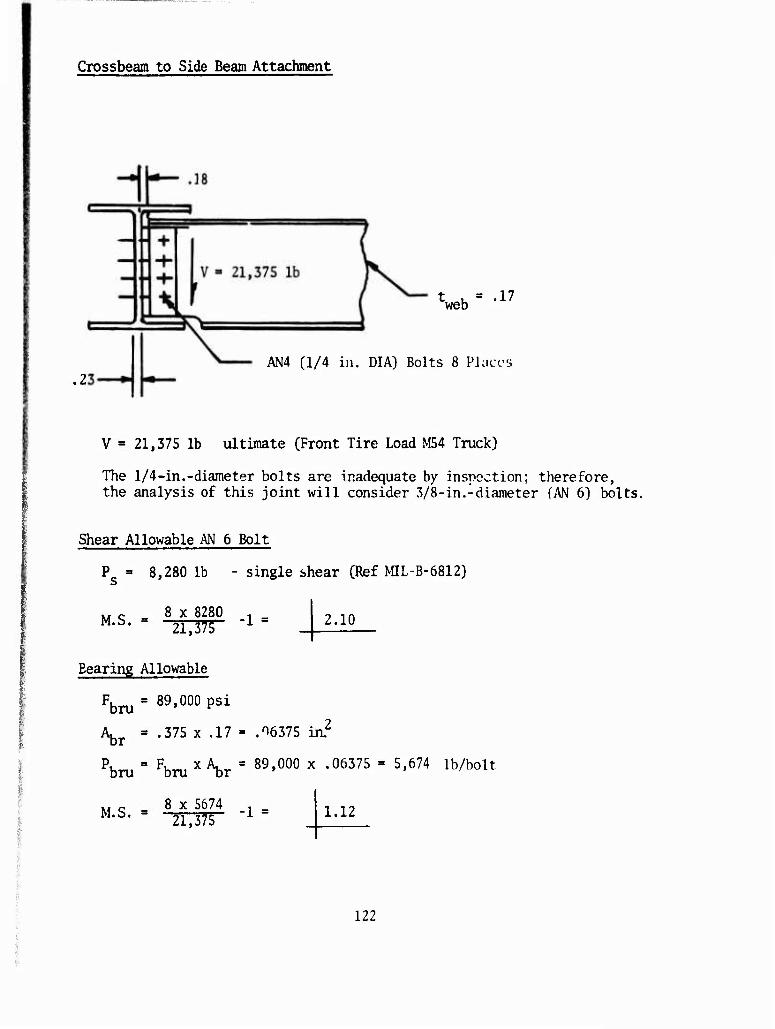
Crossbeam to Side Beam Attachment
tweb = ■17
AN4 (1/4 in. DIA) Bolts 8 Places
V = 21,375 lb ultimate (Front Tire Load M54 Truck)
The 1/4-in.-diameter bolts are inadequate by inspection; therefore, the analysis of this joint will consider 3/8-in.-diameter (AN 6) bolts.
Shear Allowable AN 6 Bolt
P » 8,280 lb - single shear (Ref MIL-B-6812)
M c 8 x 8280 , _ M-S' 21,375 ^ "
Bearing Allowable
Fbru = 89'000 psi
2.10
:_2 Abr = •375 x -i7 " ^6375 in
Pbru = Fbru x V = 89,000 x •06375 = 5'674 lb/bolt
8 x S674 M.S. = 21,375
-1 = 1.12
122
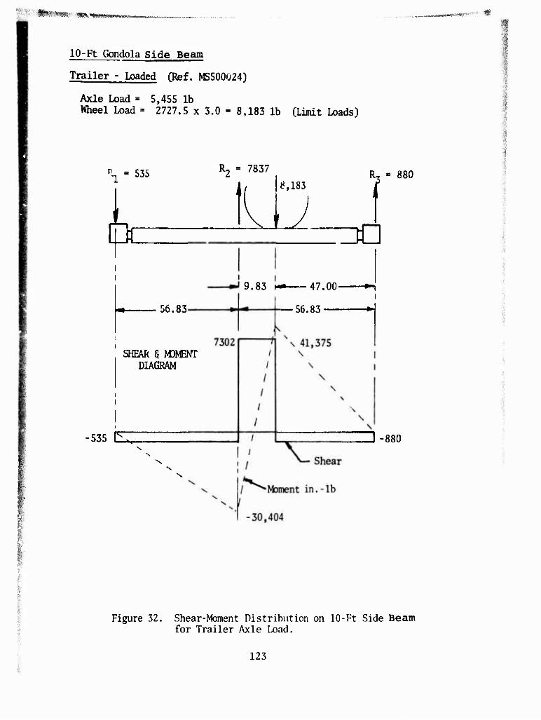
■****w HMh ^ew**-¥wwK*-* «"WW""!'"" "P
10-R Gondola side Bearo
Trailer - Loaded (Ref. MS500Ü24)
Axle Load = 5,455 lb Wheel Load = 2727.5 x 3.0 = 8,183 lb (Limit Loads)
Rj = 535 R2 = 7837
1 ii 8,183 RT = 880 1
(C ZO
i6.83
9.83 i— 47.00 »-i
56.83-—*-
SHEAR § MDMENT DIAGRAM
535 EZ
f
J -880
Figure 32. Shear-Moment nistribution on 10-Ft Side Beam for Trailer Axle Load.
123
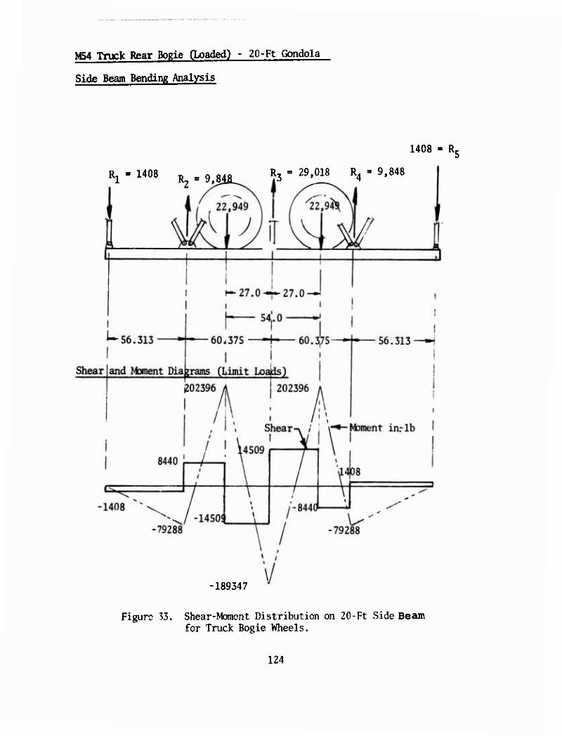
M54 Truck Rear Bogie CLoaded) - 20-Ft Gondola
Side Beam Bending Analysis
1408 - R,
R, - 1408 R3 = 29,018 R4 - 9,848
-189347
Figure 33. Shear-Momont Distribution on 20-Ft Side Beam for Truck Bogie Wheels.
124
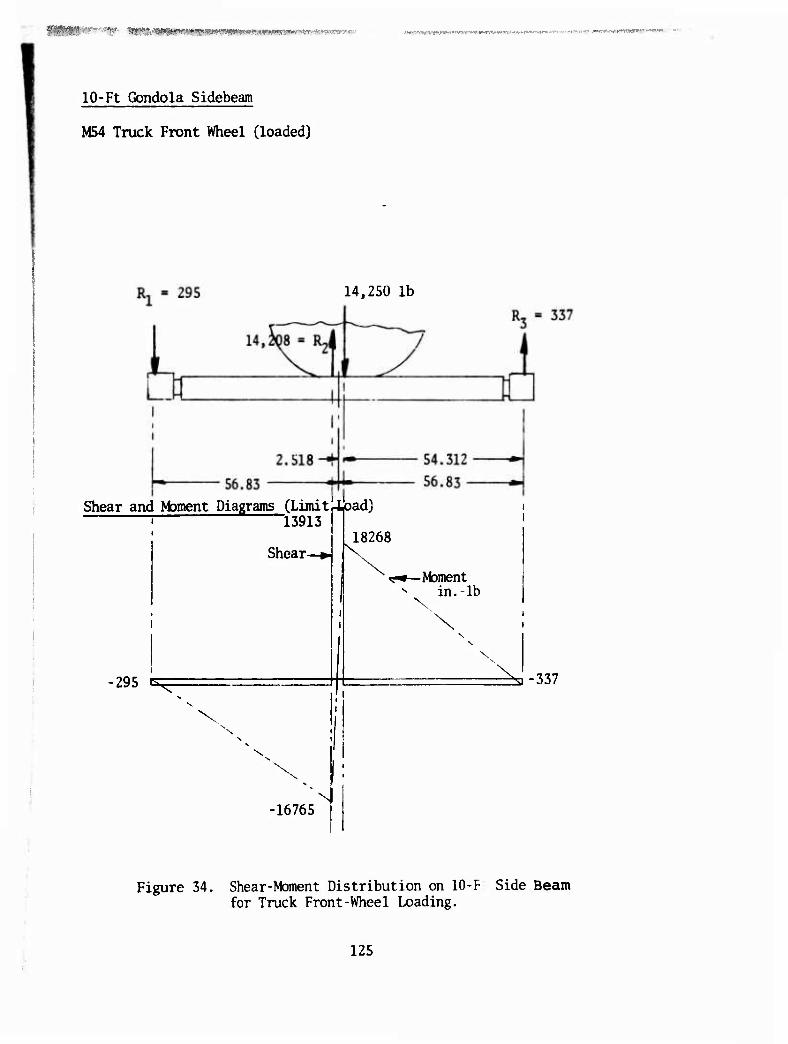
^^^mm^mmmvm p»TWfl*m»r*K''iv.' .'•w^r-T^nr ipmr«^» •'wrrw«; WMCA*»»«^ ^ »p > y.Ty-j-flniimiiia'ii «i^ii;
10-Ft Gondola Sidebeam
M54 Truck Front Wheel (loaded)
14,250 lb
Shear and Moment Diagrams (LimitrLpad) i 13913
Shear-
■295 K ",:^-
18268 K
\
-Moment in.-lb
x
\. s-337
-16765
Figure 34. Shear-Moment Distribution on 10-F Side Beam for Truck Front-Wheel Loading.
125
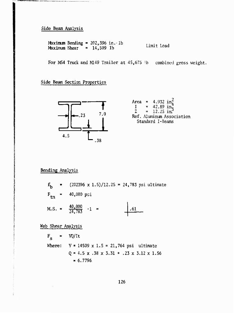
>vi*m*W*i-*t;..-**K
Side Beam Analysis
Maximum Bending Maximum Shear
202,396 in.-lb 14,509 lb Limit Load
For M54 Truck and M149 Trailer at 45,675 'b combined gross weight.
Side Beam Section Properties
T ,23 7.0
U 4.5 r .38
Area = 4.932 in.^ I = 42.89 in.! Z = 12.25 inT
Ref. Aluminum Association Standard I-Beams
Bending Analysis
tn
M.S.
(202396 x 1.53/12.25 = 24,783 psi ultimate
40,000 pci
40,000 24,783
■1 = .61
Web Shear Analysis
Fc = VQ/It
Where: V = 14509 x 1.5 = 21,764 psi ultimate
Q = 4.5 x .38 x 3.31 + .23 x 3.12 x 1.56
- 6.7796.
126
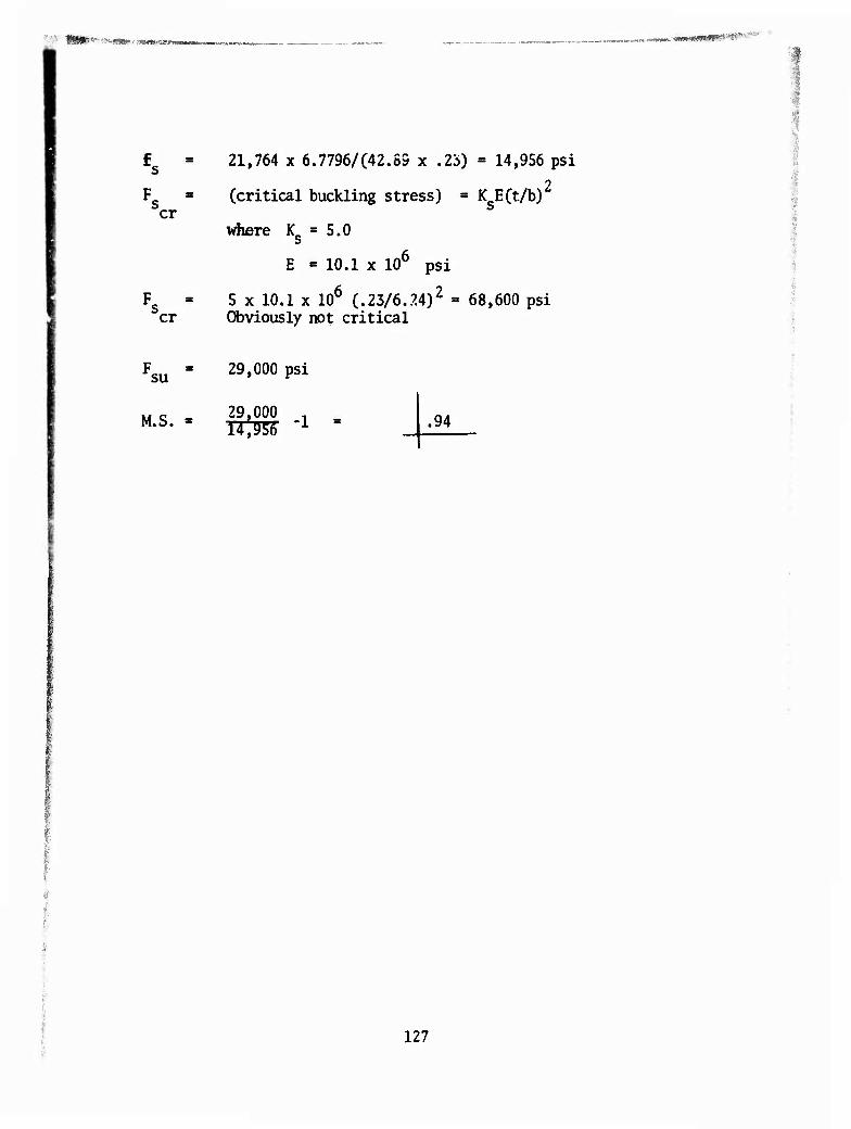
,,. , t*Tmmm*immm 0WMMWM)pr»a«ft-<.'ai'
er
er
21,764 x 6.7796/(42.89 x ,23) « 14,956 psi 2
(critical buckling stress) = K ECt/b)
where K = 5.0
E * 10.1 x 106 psi
5 x 10.1 x 106 (.23/6.24)2 = 68,600 psi Obviously not critical
su
M.S.
29,000 psi
29,000 . .94
127
W^-' ' »^SWWIWW&Wffl^i^^^ ...,,. , -.-: t-'.j.,».^^«^^
CONCLUSIONS
1. From the operating characteristics of the three helicopters, two gondola sizes were identified; however, three sizes can be achieved with a coupling of two gondola units.
2. Cargo density and size would suggest 1,000 cu ft capacity for the CH-47/CH-54 and 2,500 cu ft capacity for the HLH, with a payload capacity of 25,000 lb and 60,000 lb respectively. A width of 8 ft would be ade- quate transport for many vehicles and equipment and break-bulk cargo as required.
3. Stability of the gondola is significantly improved when two or more helicopter attachment points are available. A gondola load attached to a single-point helicopter will fly broadside with significant trail angle and parasitic drag. Attachment points to the load should be above the CG to prevent overturning. Attachiuent to the helicopter must be accom- plished by a sling/pendant/hoist system that will not induce vertical bounce at any load capacity.
4. The gondola should be constructed of rugged structural shapes for the main framing members. Materials must be corrosion resistant and of a thickness such that puncture and abrasion would not render the structure unserviceable. The use of extruded aluminum alloy 6061-T6 should be used as the primary structural material. The use of sheet stock must be avoided.
5. Basically, standard rigging materials can be used in securing cargo. However, existing ground mobility equipment is not compatible with the fully loaded gondolas. Slings should be compatible with the gondolas.
6. The gondola has great potential to be used throughout the system from CCNUS through forward resupply; however, it appears that local resup- ply of advance bases may be better suited to a smaller gondola.
7. The gondola is suited to all modes of transportation if the 8-ft width and 20- or 40-ft length is maintained. However, for fixed-wing transportability, the gondola must be used with the 463L pallet as a slave and would require additional structure for the 9G crash survivability.
8. The gondola is both personnel and cost effective by providing uniform rigging practices and better utilization of manpower. A significant labor saving is experienced when transhipment of cargo is avoided, as can be realized with a gondola when introduced in CONUS deliveries. In heli- copter deliveries alone, it is estimated that the gondola cost could be recovered in as few as five missions.
128
*'^' ^ww^s^äwrÄw^^^ : .:
CONCLUSIONS
1. From the operating characteristics of the three helicopters, two gondola sizes were identified; however, three sizes can be achieved with a coupling of two gondola units.
2. Cargo density and size would suggest 1,000 cu ft capacity for the CH-47/CH-54 and 2,500 cu ft capacity for the HIH, with a payload capacity of 25,000 lb and 60,000 lb respectively. A width of 8 ft would be ade- quate transport for many vehicles and equipment and break-bulk cargo as required.
3. Stability of the gondola is significantly improved when two or more helicopter attachment points are available. A gondola load attached to a single-point helicopter will fly broadside with significant trail angle and parasitic drag. Attachment points to the load should be above the CG to prevent overturning. Attachment to the helicopter must be accom- plished by a sling/pendant/hoist system that will not induce vertical bounce at any load capacity.
4. The gondola should be constructed of rugged structural shapes for the nuiin framing niembers. Materials must be corrosion resistant and of a thickness such that puncture and abrasion would not render the structure unserviceable. The use of extruded aluminum alloy 6061-T6 should be used as the primary structural material. The use of sheet stock must be avoided.
i
5. Basically, standard rigging materials can be used in securing cargo. However, existing ground mobility equipnent is not compatible with the fully loaded gondolas. Slings should be compatible with the gondolas.
6. The gondola has great potential to be used throughout the system from CONUS through forward resupply; however, it appears that local resup- ply of advance bases may be better suited to a smaller gondola.
7. The gondola is suited to all modes of transportation if the 8-ft width and 20- or 40-ft length is maintained. However, for fixed-wing transportability, the gondola must be used with the 463L pallet as a slave and would require additional structure for the 9G crash survivability.
8. The gondola is both personnel and cost effective by providing uniform rigging practices and better utilization of manpower. A significant labor saving is experienced when transhipment of cargo is avoided, as can be realized with a gondola when introduced in CONUS deliveries. In heli- copter deliveries alone, it is estimated that the gondola cost could be recovered in as few as five missions.
128
1 K*tn-mi*W(l^XV»lllSf*m*r*''. 7 ■ nrtfrrfn;i'r>»i>mv^. 11M H ■»K»U(P!f«lll»*W«?!«,»»*?^'*W
9. The design concept selected should provide the load and cubic capa- city over a continuous floor that is uninterrupted by support structures. Four lift points are preferred, and they must be above the load CG. A single lift point on smaller gondolas may be acceptable, but it also shall be above the floor.
10. The preferred concept should be so configured as to satisfy the three helicopters. The selected concept presented has this capability.
11. Cost effectiveness can be demonstrated by the capability of the gondola to transport a multiplicity of vehicle or equipment units, there- by reducing the number of trips and attendant helicopter operating costs.
12. Personnel effectiveness is improved by rigging from the same fixed points rather than many different hoisting points for each vehicle or piece of equipment.
13. The reliability of the gondola will demonstrate 95% probability of completing the helicopter mission.
14. Availability of the gondola is based on 24-hour utilization of 2/3 year for 5,840 hours.
15. Maintenance ratio shall not be greater than 0..1, which would allow 58.4 hours annually. This should be more than adequate since it is over 50% of the time required for fabrication.
16. Tare weight savings on a 20-ft gondola is nearly 50% that of an equivalent 20-ft container. Weight savings on a 40-ft gondola is over 20%. In addition, the payload for the 40-ft gondola is approximately 10,000 lb greater in the rotary-wing transport mode.
RECOMMENDATIONS
It is recommended that one unit of the preferred concept be fabricated and tested. The unit would be comprised of two 10-ft sections and a 20-ft mid-section. The unit would be bench tested followed by flight testing through a full spectrum of its utilization cycle.
129
REFERENCES CITED
1. Berger, S., Heider, F., Lechus, J., Ralston, R., Watson, I., A CRITICAL ANALYSIS OF THE STATE OF THE ART IN CONTAINERIZATION; Control Systems Research In., United States Army Mobility Equip- ment Research and Development Center, Ft. Belvoir, Virginia, November 1970, AD-877259L
2. Wood, Charles W., Watts, John H., Lucas, Robert M., DESIGN CRITERIA TECHNICAL CHARACTERISTICS, AND DESIGN CONCEPTS FOR AN AIR TRANS- PORiAßLE CONTAINER, Aurthus D. Little, In.,; USAAML Technical Report 65-36, U. S. Army Aviation Materiel Laboratories, Fort Eustis, Virginia, June 1965, AD-619158
3. Brizinski, S. J., Karras, G. R., CRITERIAL FOR EXTERNALLY SUSPENDED HELICOPTER LOADS; USAAVLABS Technical Report 71-61, U. S. Army Aviation Materiel Laboratories, Fort Eustis, Virgi-nia, November 1971
4. Huebner, Walter E., DESIGN GUIDE FOR LOAD SUSPENSION POINTS, SLINGS, AND AIRCRAFT HARD POINTS; ISAAMRDL Technical Report 72-36, U. S. Army Air Mobility Research and Develooment Laboratory, Fort Eustis, Virginia, July 1972, AD-747814
5. Lehmann, Maurice John William; Captain, AERODYNAMIC CHARACTERISTICS OF NON-AERODYNAMIC SHAPES, Air Force Institute of Technology, Wright-Patterson Air Force Base, June 1968
6. Gabel, Richard, Wilson, Gregory; TEST APPROACHES TO EXTERNAL SLING LOAD INSTABILITIES, Vertol Division, The Boeing Co.
7. Bradley, J., Toms, G., BRIDGE EMPLACEMENT TRIALS-I^IASE II USING CH-47A AND CH-54A HELICOPTERS; Aeroplane and Armament Experimental Establishment, Boscombe Down, United Kingdom
8. Krolikiewicz, DESIGN, DEVELOPMENT, FABRICATION, AND TESTING OF SMALL AND LARGE LOAD-BEARING PALLETS FOR THE CH-54 "FLYING CRANE" HELI- COPTER; Brooks 5 Perkins Inc., USAAVLABS Technical Report 68-71, U. S. Army Aviation Materiel Laboratories, Fort Eustis, Virginia, October 1968, AD-680283
9. Military Handbook Strength of Metal Aircraft Elements, Department of Defense, MIL-HDBK-5, 1 September 197''.
10. Military Handbook Plastics for Aerospace Vehicles, Department of Defense, MIL-HDBK-17A, January 1971
11. FM 101-10-1 STAFF OFFICERS FIELD MANUAL, July 1971
130
Wemmm " mmznusmt** ,-■".-»
12. TM 55-450-8, Air Transport of Supplies and Equipment, External Trans- port Procedures, December 1968
13. TM-55-450-11, Air Transport of Supplies and Equipment Helicopter External Loads, Rigged with Air Delivery Equipment. June 1968
14. IM 55-450-12, Air Transport of Supplies and Equipment Helicopter External Loads for Sling, Nylon Chain, Multiple Leg (15,000 LB CAP) June 1969
15. TM 55-450-19, Air Transport of Supplies and Equipment, Helicopter External Lift Rigging Materials Techniques and Procedures
16. TM 55-1520-217-10/2 Operators Manual CH-54A Helicopter, February 1969
17. TM 55-1520-227-10 Operators Manual CH-47B/C Heliconters, December 1961
18. Vichness, J. A., Deacon, J.A., CARGO COMPARTMENT OPTIMIZATION STUDY, ARMY TRANSPORT AIRCRAFT; USAAVLABS Technical Report 66-79, U. S. Army Aviation Material Laboiatories, Fort Eustis, Virginia.
19. Finlay, Patrick, JANES FREIOTT CONTAINERS, 1972-1973, Fifth Edition
20. Hone, Horace T., Huebner, Walter E., DEVELOPMENT OF CARGO SLINGS WITH NON-DESTRUCTIVE CHECKOUT SYSTEMS; Interim Technica Report, Sikorsky Aircraft Division of United Aircraft, U. S. Army Air Mobility Research and Development Laboratory, Fort Eustis, Virginia, DAAJ02-72-C-0008
21. Lancashire, T., et al INVESTIGATION OF THE MECHANICS OF CARGO HANDLING BY AERIAL CRANE-TYPE AIRCRAFT; Vertol Division, The Boeing Co., USAAVLABS Technical Report 66-63 U. S. Army Aviation Material
22. Burroughs, Lester R., Ralsten, Harold E. . DESIGN STUDY OF HEAVY LIFT HELICOPTER EXTERNAL LOAD HANDLING SYSTEMS, Sikorsky Aircraft, Division of United Aircraft Corporation, USAAVLABS, Technical Report 67-46, U. S. Army Aviation Materiel Laboratories, Fort Eustis, Virginia, November 1967, AD-828283
'. 23. FM 55-70, Army Transportation Container Operations, the U. S, Army
Transportation School, July 1973
24. TB 55-46-2, Standard Characteristics (Dimensions, Weight and Cube) For Transportability of Military Vehicles and Equipment.
25. American National Standard MIS. 1-1970, Eleventh Draft, June 1, 1970
26. MIL-A-8142C (USAF) Air Transportability Requirements, General Spec- ification For, 14 August 1969
131
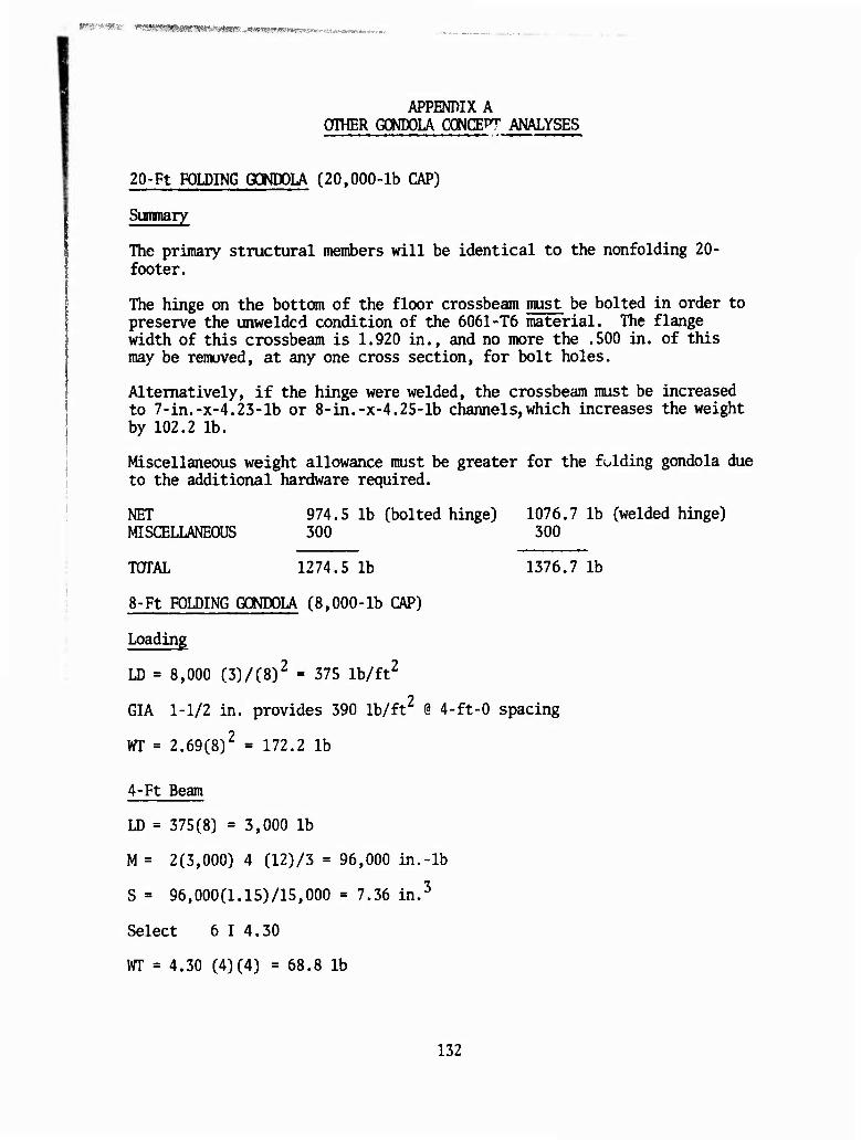
,«"•■;: «WB* ^fflmwrnwrnvtmi .i><^<^mrKr.V!Sr^.;.. .'.uhWW*»'*«»« ««•*■»*
APPENDIX A OTHER GONDOLA CONCEPT ANALYSES
20-Ft FOLDING GONDOLA (20,000-lb CAP)
Sunanary
The primary structural members will be identical to the nonfolding 20- footer.
The hinge on the bottom of the floor crossbeam must be bolted in order to preserve the unweldcd condition of the 6061-T6 material. The flange width of this crossbeam is 1.920 in., and no more the .500 in. of this may be removed, at any one cross section, for bolt holes.
Alternatively, if the hinge were welded, the crossbeam must be increased to 7-in.-x-4.23-lb or 8-in.-x-4.25-lb channels,which increases the weight by 102.2 lb.
Miscellaneous weight allowance must be greater for the folding gondola due to the additional hardware required.
NET 974.5 lb (bolted hinge) 1076.7 lb (welded hinge) MISCELLANEOUS 300 300
TOTAL 1274.5 lb 1376.7 lb
8-Ft FOLDING GONDOLA (8,000-lb CAP)
Loading
LD = 8,000 (3)/(8)2 = 375 lb/ft2
GIA 1-1/2 in. provides 390 lb/ft2 @ 4-ft-0 spacing
m = 2.69(8)2 = 172.2 lb
4-Ft Beam
LD = 375(8) = 3,000 lb
M = 2(3,000) 4 (12)/3 = 96,000 in.-lb
S = 96,000(1.15)/15,000 = 7.36 in.3
Select 6 I 4.30
WT = 4.30 (4)(4) = 68.8 lb
132
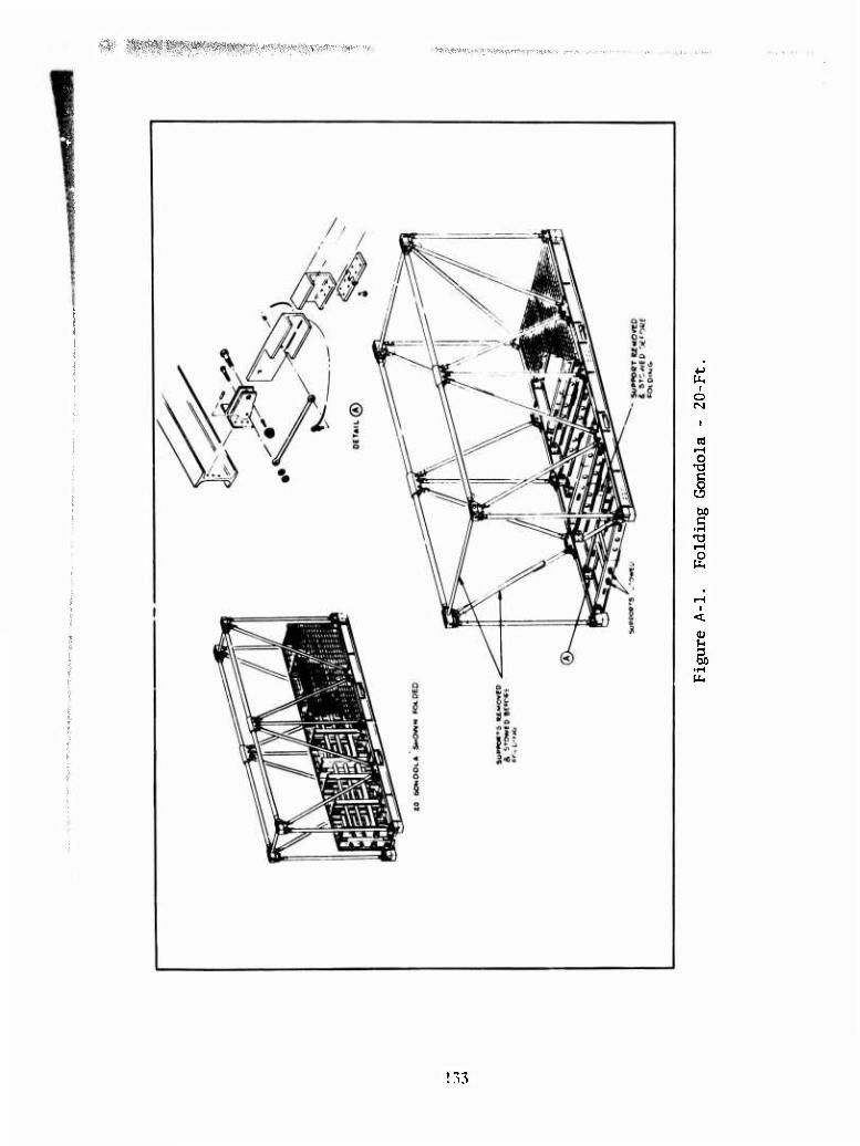
i&S&iR&W f^W*^ftip^t»^pr»IB«*W: ■>" P- ■
I o
I •H
i-i
0)
I •H
! 33
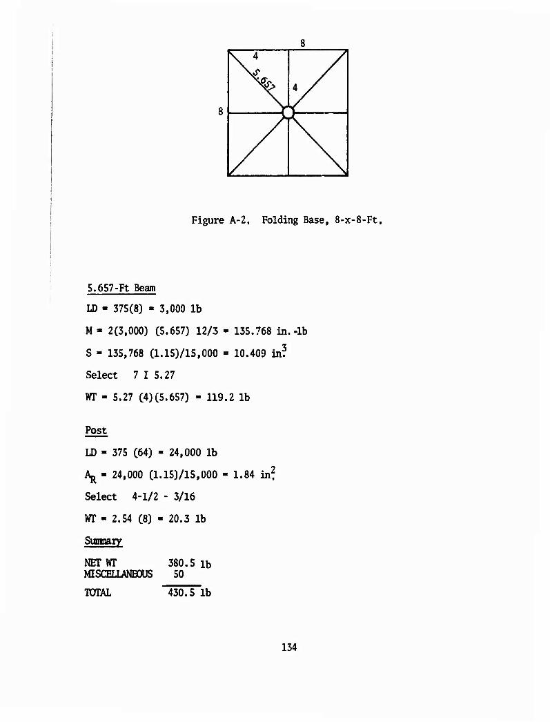
N 4
* /
N Figure A-2. Folding Base, 8-x-8'Ft.
5.657-Ft Beam
ID - 375(8) - 3,000 lb
M- 2(3,000) (5.657) 12/3 - 135.768 in.-lb
S - 135,768 (1.15)/15>000 - 10.409 in?
Select 7 I 5.27
WT - 5.27 (4)(5.657) - 119.2 lb
Post
LD - 375 (64) - 24,000 lb
Aj^ - 24,000 (1.15)/15,000
Select 4-1/2 - 3/16
WT - 2.54 (8) - 20.3 lb
Sumnary
NET WT 380.5 lb MISCELLANEOUS 50
1.84 in?
TOTAL 430.5 lb
134
n/^ttvmitMt&^x^iy^^-
c r j
X i
o c c
o
OG
o
i .>:
ffiVp^pnumuwM""'W^-ni-i-»--*.'^- ■".■.■.
Soft Base Gondola
This concept was generated to minimize the deficiencies inherent in a cargo net while taking advantage of lightweight nets and high-density stowage. The concept is indeed lightweight but has limited utilization beyond the helicopter transportation mode. This concept was analyzed for structural sizing, and the results are presented in Table A-l.
w
M-i
S5
s a'
£ £ e
I O
« 'S in c g ti in g 111 s O H H ^ O
iH iH
O
in
CO
o
Is-
o o
.0,0.0 "O. iH i-l iH
XI XI
LO IT) O O LT» r-i «N o \o <NI vO vO O NO vO
«k » •« M M 00 00 LO C) 00
rsi (N tn »oroi^-oot^c^«<oot^. »* TJ- N H Z
CM rg
i-l iH »O
vO VO «N ^t
o »o to « »o to I I
C-J
to I
0)
to I
iH
\o I o
to
iH
136
■W)i?6«w»"WW^A«sw*«i^^ ~i'm**m,iram'tj*i*vm*me<ez*>ifn *wwvf«a1«^.?^f^3^*.1lW,?•'!W&?•!*^
20-Ft BOEING MATERIALS HANDLING DEVICE (20,000-lb CAP) (REF Pat. 3580,403) i
LOADING
LD = 20,000 (3)/8(20) = 375 lb/£t2
CROSSBEAM (4-Ft Pallet)
LD = 375 (4)(4)/2 = 3,000 lb
M = 3,000 (24) = 72,000 in.-lb
S = 72,000 (1.15)/15,000 = 5.52 in.3
Select 6 I 4.30
WT = 4.30 (4)(20) = 344.0 lb
CENTER BEAM
LD = 375 (8)20 = 60,000 lb
M = 60,000 (20)12/8 = 1,800,000 in.-lb
S = 1,800,000 (1.15)/15,000 = 138.00 in.3
There is no standard I-beam large enough.
Estimated weight of beam is 50 (20) = 1,000 lb
POSTS
LD = 30,000 lb
Aß * 30,000 (1.15)/15,000 = 2.70 in.2
Select 4-3/4 - 3/16
WT = 3.161 (8)(2) = 50.6 lb
137
A - .125 [ ] - .575 in?
WT » .575 { C2 x 120) + (2 x 96) + (2 x 154)} (.1) = 43 lb
Spreader Bar
LD - 30,000 sin 30° * 15,000
2. C240)2 15.000 Y A - ^ \ y TT 10
min is 5-1/4 - 3/16
WT = 3.507 (20) » 70.1 lb
4x4 Pallets
WT = 665.7 lb
Cradle
Not included since it does not fly.
Summary
NET WT 2505.4 lb MISCELLANEOUS 275
TOTAL WT 2780.4 lb
RIGID-BASE PALLET CELL GONDOLA 17-x-7-x-8-Ft (SK78001905)
This concept was designed around a commercially available polystyrene pallet. The support structure is similar to that used for the wood pallet. It was initially conceived to support the pallet about its edge, which proved to be inadequate. However, with more support structure and added weighc, the pallet could be utilized. The advantage of the plastic pallet is its stackability and potentially lower life-cycle cost than that of the wooden pallet.
138
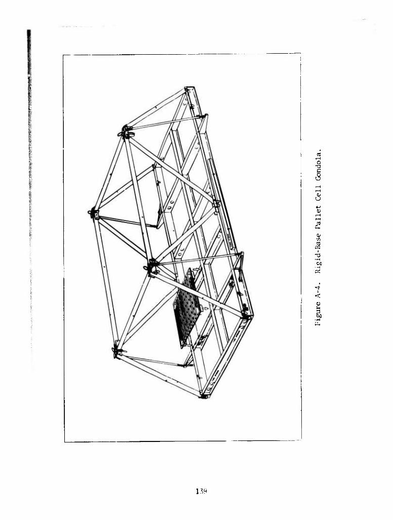
c 5 (Li u a>
2
CO
t I
<
1.^
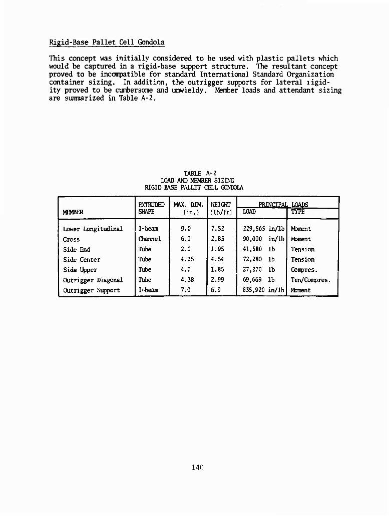
Rigid-Base Pallet Cell Gondola
This concept was initially considered to be used with plastic pallets which would be captured in a rigid-base support structure. The resultant concept proved to be inconqpatible for standard International Standard Organization container sizing. In addition, the outrigger supports for lateral ligid- ity proved to be cumbersome and unwieldy. Member loads and attendant sizing are summarized in Table A-2.
TABLE A-2 LOAD AND MEMBER SIZING
RIGID BASE PALLET CELL GONDOLA
MEMBER EXIRUDED SHAPE
MAX. DIM. (in.)
WEIGHT (lb/ft)
PRINCIPAL LOADS i LOAD TYPE |
Lower Longitudinal I-beam 9.0 7.52 229,565 in/lb Moment
Cross Channel 6.0 2.83 90,000 in/lb Mament
Side End Tube 2.0 1.95 41,580 lb Tension
Side Center Tube 4.25 4.54 72,280 lb Tension
Side Upper Tube 4.0 1.85 27,270 lb Conpres.
Outrigger Diagonal Tube 4.38 2.99 69,669 lb Ten/Conpres.
Outrigger Support I ■■'beam 7.0 6.9 835,920 in/lb Moment 1
140
«^«»w^^KMiBaiw«^^ ■ • ■ '.■--* ■.:•,.■,v-,-"« M^rmmtmmmvmBii,. M WIMimMn«
APPENDIX B GONDOLA SIZING METHODOLOGY
SIZING METOODOLOGY FOR SQUARE GONDOLA
Gondola sizing was initiated by considering area density and cubic density as parameters to optimize design geometry. Figure B-l shows that maximum area density is achieved when the suspended load is a cube. Figure B-2 compares area density for cubic gondolas from 5- to 10-ft with various cubic densities. This analysis demonstrates that cubic gondolas achieve maximum area density between 5 and 7 ft. Figures B-3 through B-7 sum- marize the principal framing member weights as a percentage of tare weight. The greatest impact occms for the floor beams; however, the floor grating decreases as cargo density increases. It is noted that the floor beams and grating a^e most affected by cargo cube density.
Figures B-8 and B-10 compare cubic and oblong gondolas as a function of tare weight. A comparative analysis of a cubic gondola and an oblong one (base length exceeds width) shows that tare weight is increased approx- imately 1/2% over a cubic gondola for a 20,000-lb capacity. However, a gondola for 50,000 lb becomes more efficient when configured with an 8-x-40-ft floor plan. Figure B-10 demonstrates that as length increases, oblong gondolas become more efficient than cubic configurations.
Following the graphical displays is the analysis of cubic and oblong gon- dolas at 20,000 lb and 50,000 ib capacities, which are in the range of the helicopter payloads. The analysis shows that the oblong gondola becomes more efficient in transporting loads in excess of 30,000 lb. This sizing analysis demonstrates that tare weight of an oblong gondola is not sig- nificantly greater than that for a cubic gondola. Therefore, the gondola may be sized to meet ANSI/I SO geometry consistent with the payload require- ments of the helicopter.
t
141
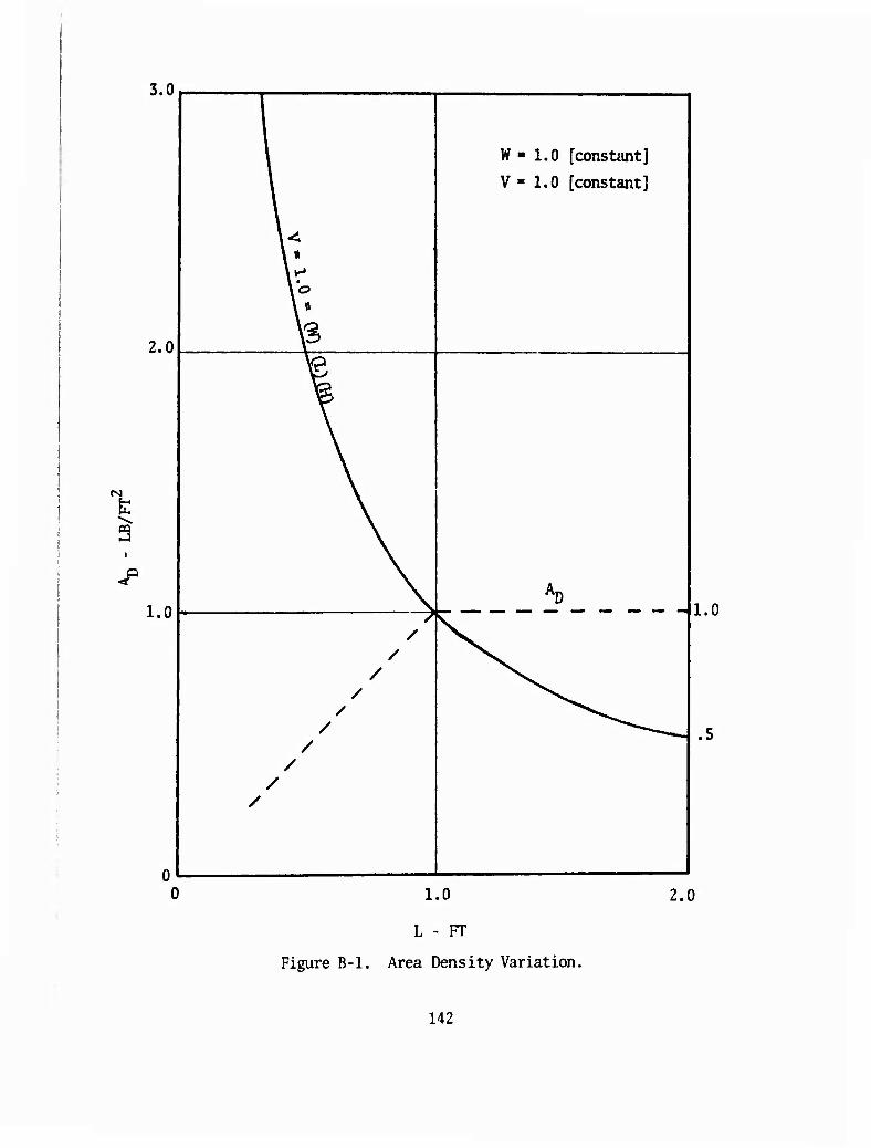
3.0
2.0
rg
3
<P
1.0
\ * '
\ \ *
i
W « 1.0 [constant]
V - 1.0 [constant] |
V
^ I /
/ /
/ /
/ /
/ \ /
R^ 1.0 .5
1.0
L - FT
Figure B-l. Area Density Variation.
2.0
142
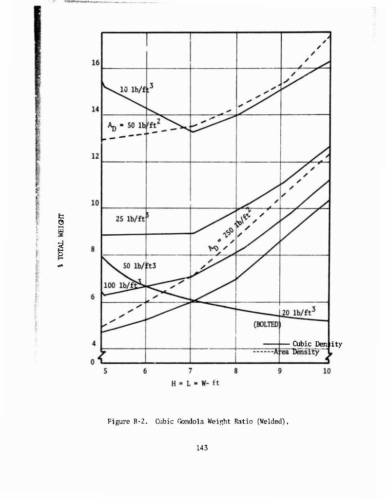
"•'•""•J""T--rrf T-mrmwimimnu,.,
tw>
Cubic Den ity
Figure B-2. Cubic Gondola Weight Ratio (Welded).
143
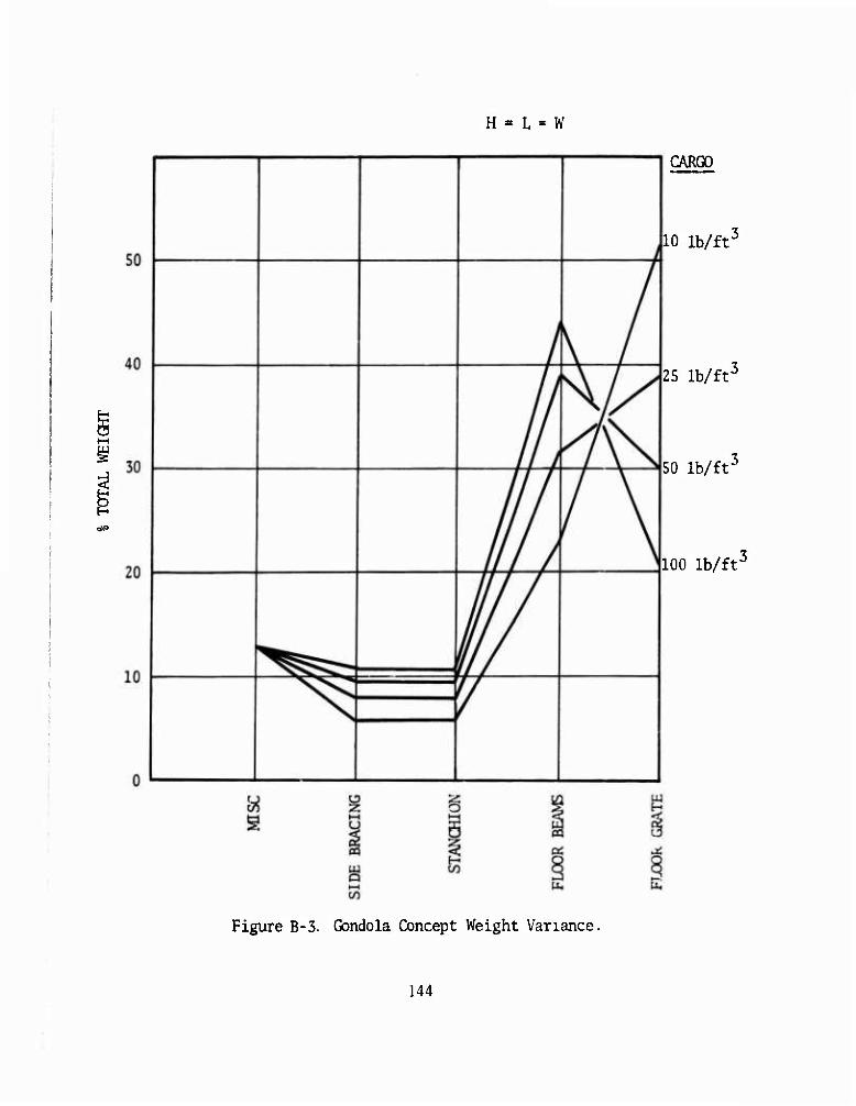
H = L = W
CARGO
10 lb/ft*
25 lb/fr
50 lb/ft'
100 Ih/ff
Figure B-3. Gondola Concept Weight Variance.
144
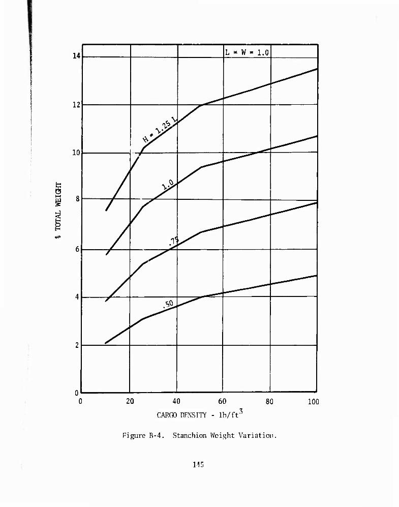
14
12
10
<*>»
L = W = 1.0
1
^ \
1 J /
^
/
/
/
>-
^ ^ ^\
/
/
—j &,
- —J 20 40 60 80
CAP.CO DENSITY - lb/ft 3 100
Figure R-4. Stanchion Weight Variation
115
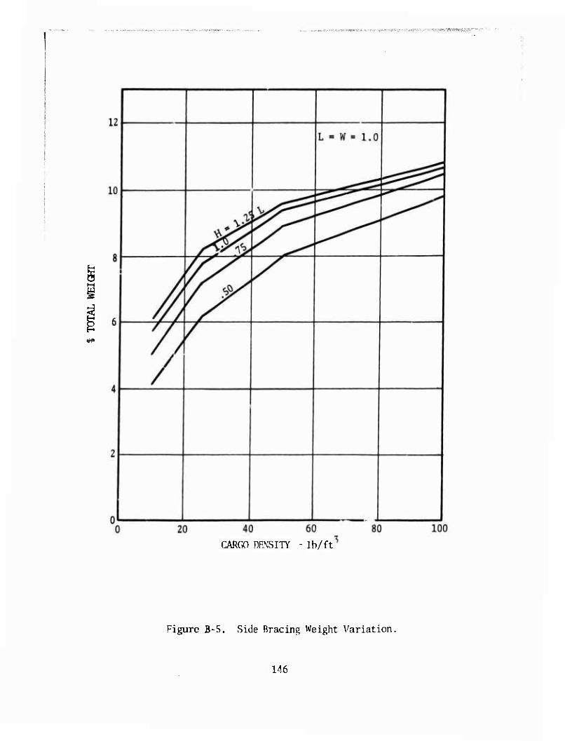
, , .. ^^-.v,..^-.^.'-!*----«';^-*-* V-P-P-^JJ^'^IP.V;.'-., ■>-■.■■ ' ■■.■^'^f^St^^'J^'^'
CARGO DRNSITY - lb/ft
Figure B-5. Side Bracing Weight Variation.
146
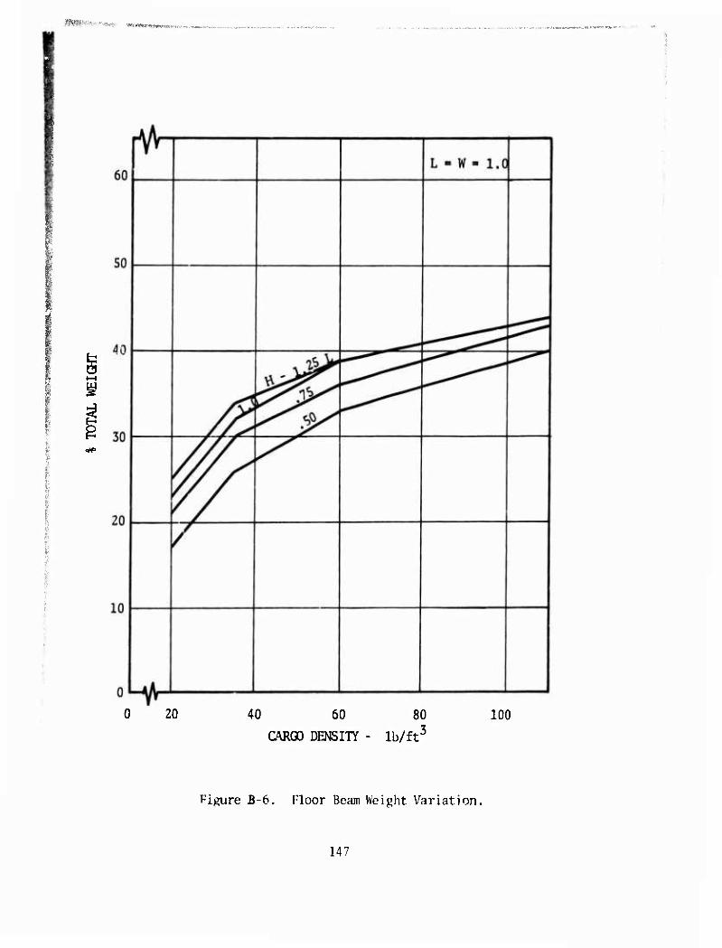
^^•■-V.* ■- ".^..-^ , •J*f,HflKr*MVl^lWt.<„
■g
^
0 20 40 60 80
CARGO DENSITY - lb/ft3 100
Pigure B-6. Floor Beam Weight Variation,
147

1 PPT1.^» ■ ■■• ^VMWMi'^Ma^w. MBMMMMMMMHMOHMMim'inMMMii ^wmww^ mw-
^■-^«.■j-i-iwiwerKWJ«—«»**
60
50
40
30
20
10
pF"
L = W = 1.0
K ! u
^^^^^^ S3 1
LA^ o f. 0 ' 20 40 60
CARGO DENSITY - lb/ft
80 3
100
Figure B-7 Floor Grate Weight Variation.
148
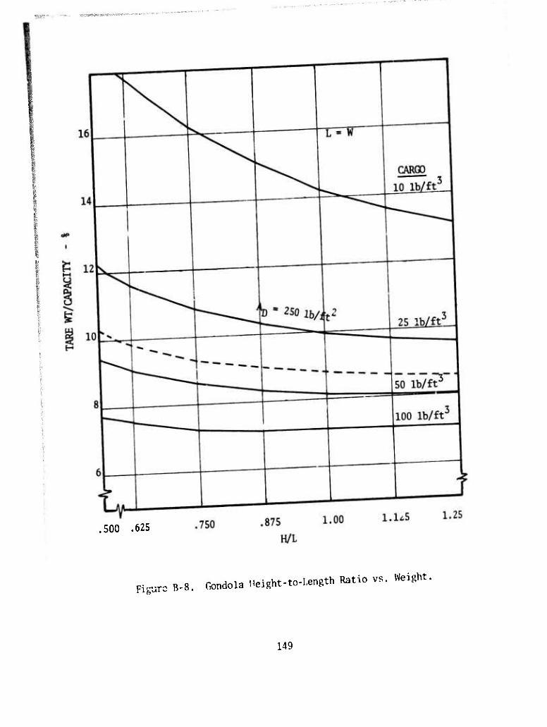
w WRUIIWWWWWW*1»^ j.
.500 .625
Figure B-8, Gondola Height-to-Length Ratio vs. Weight.
149
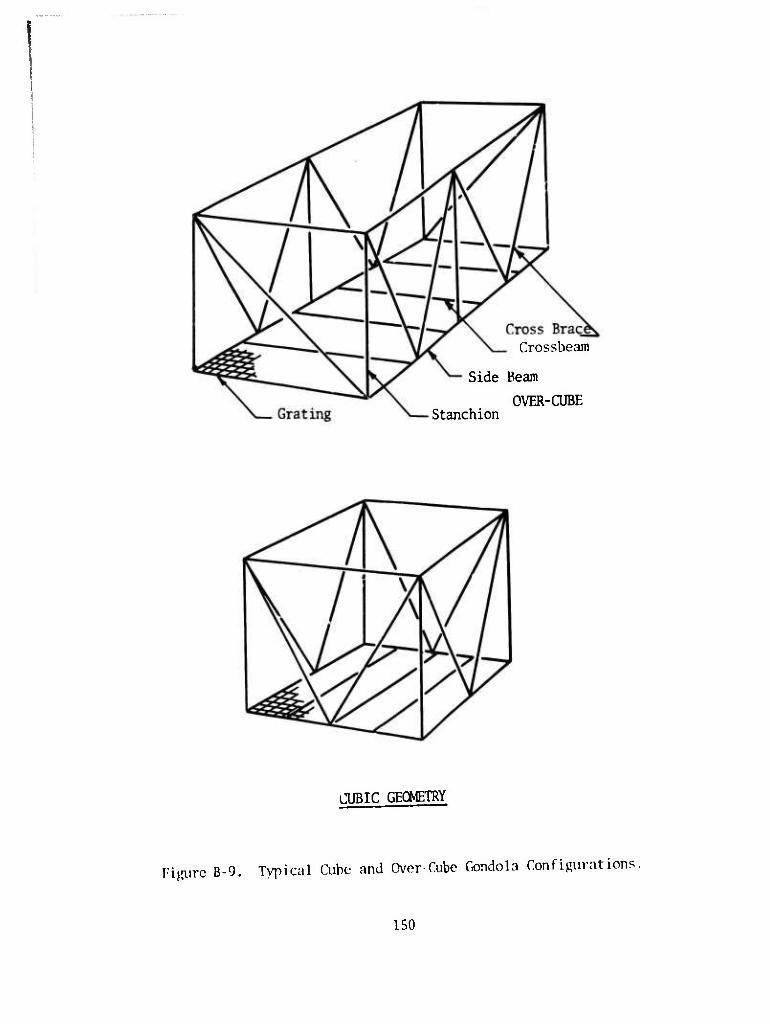
Crossbeam
Side Beam
OVER-CUBE Stanchion
CUBIC GEOMETRY
Figure B-CJ. Typical Cube and Over-Cube Gondola Configurations.
150
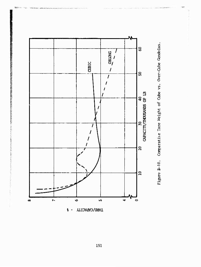
*»*» T-K*. ^^»-■mf.ti*!/,- i^*«ni«,-n»rt.i-
r^n
u
o /
I7 PQ
/
/
/ /
/
1
1 /
/ l / I
/ I / \
/ / s \
VN / 1
J/
^J
o
O
a 5fe
o to
o CM
■8 J I
>
^
H
03
03
U
•H
00 1/1
% - AIIDVdVD/HWl
151
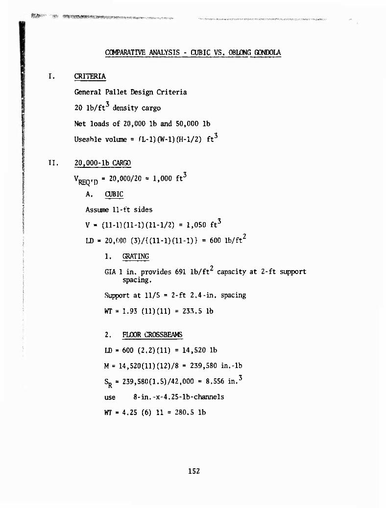
'*' "*' ^^KU^mmWmmßsmmiitm'Mmv^mifv^f^-^ ■*m~m:.m**m.,>^r^nm^m^^mm^mmw^mm^^v-m^mVmm.<
COMPARATIVE ANALYSIS - CUBIC VS. OBLONG GCMJOLA
I. CRITERIA
General Pallet Design Criteria
20 lb/ft density cargo
Net loads of 20,000 lb and 50,000 lb
Useable volume = fL-l)(W-l)(H-l/2) ft3
II. 20,000-lb CARGO
V^Q.p = 20,000/20 = 1,000 ft3
A. CUBIC
Assume 11-ft sides
V = (11-1)(11-1) (11-1/2) = 1,050 ft3
LD = 20,000 (3)/{(11-1)(11-1)} = 600 lb/ft2
1. GRATING
GIA 1 in. provides 691 lb/ft capacity at 2-ft support spacing.
Support at 11/5 = 2-ft 2.4-in. spacing
m = 1.93 (11)(11) = 233.5 lb
2. FLOOR CROSSBEAMS
LD = 600 (2.2) (11) = 14,520 lb
M = 14,520(11)(12)/8 = 239,580 in.-lb
Sj^ = 239,580(1.5)/42,000 = 8.556 in.3
use 8-in.-x-4.25-lb-channels
m = 4.25 (6) 11 = 280.5 lb
152
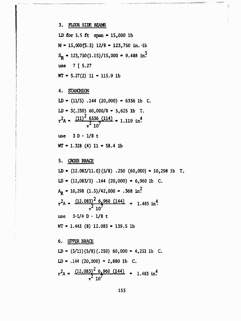
...„-.,... ■.■,f)v ««nwMtMnwh ui. <u>itlWJiW1^W "" W&pW
3. FLOOR SIDE BE/ttB
LD for 5.5 ft span - 15,000 lb
M - 15,000C5.5) 12/8 - 123,750 in.-lb
Sj^ - 123,750(1.15)/15,000 - 9.488 in?
use 7 I 5.27
VT - 5.27(2) 11 - 115.9 lb
4. STANCHION
LD - (11/5) .144 (20,000) - 6336 lb C.
LD - 3(.250) 60,000/8 - 5,625 lb T.
r2A. (II)2 63367C114) , ltll9 ^4
ir 10
use 3 D - 1/8 t
WT - 1.328 (4) 11 - 58.4 lb
5. CROSS BRACE
LD - (12.083/11.0)05/8) .250 C60,000) « 10,298 lb T.
LD - (12,083/5) .144 (20,000) - 6,960 lb C.
Aj^ - 10,298 (1.5)/42,000 - .368 in?
r2A - (12.083)2 6 960 (144) . im ^4 / 10/
use 3-1/4 D - 1/8 t
m - 1.443 (8) 12.083 - 139.5 lb
6. UPPER BRACE
LD - (5/11) (5/8) (.250) 60,000 = 4,251 lb C.
LD - .144 (20,000) = 2,880 lb C.
r2A - (12-083)2 6^960 (144) , ^ ^4
153

6. UPPER BRACE (continued)
use 2-3/4 D - 1/8 t
VT - 1.212 Cll) 4 - 53.3 lb
7. SJUJAgy 11 FOOT CUBIC (20,000 LB CAP )
Grating - Gary GIA - lin. Floor Cross Beam Floor Side Beam Stanchion Cross Brace Upper Brace
NET MISCELLANEOUS
TOTAL
B. OBLONG
Assume 8-x-20-x-8-ft
233.5 lb 280.5 lb 115.9 lb 58.4 lb
139.5 lb 53.3 lb
881.0 lb 135.0 lb
1,016.0 (5.081)
V - (20-1)(8-1/2) (8-1) = 997.5 ft3
This is the standard 20-£t gondola previously analyzed. i
WT - 1124.5 lb
C. CONCLUSION
Cubic WT - 1,016.0 lb (5.08%)
Oblong WT - 1,124.5 lb (5.62%)
WT penalty is 108.5 lb or 11% of tare of cubic.
III. 50,000 LB. CARGO
VREQ!D ■ 50»000/20 " 2»S00 ft3
154
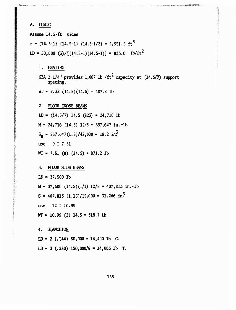
i
A. CUBIC
Assume 14.5-ft sides
r - (14.5-1) C14.5-1) (14.5-1/2) - 2,551.5 ft3
LD - 50,000 C3)/[(14.5-1)C14.5-1)] » 823.0 lb/ft2
1. GRATING
GIA 1-1/4" provides 1,007 lb /ft2 capacity at (14.5/7) support spacing.
WT - 2.32 (14.5)014.5) * 487.8 lb
2. FLOOR CROSS BEAMS
LD » (14.5/7) 14.5 (823) » 24,716 lb
M- 24,716 (14.5) 12/8 = 537,647 in.-lb
Sj^ - 537,647(1.5)/42,000 = 19.2 in?
use 9 1 7.51
yrr - 7.51 (8) (14.5) »871.2 ib
3. FLOOR SIDE BEAMS
LD - 37,500 lb
M - 37,500 (14.5)(1/2) 12/8 » 407,813 in.-lb
S - 407,813 (1.15)/15,000 » 31.266 in?
use 12 I 10.99
VlTT • 10.99 (2) 14.5 » 318.7 lb
4. STANCHION
LD - 2 (.144) 50,000 » 14,400 lb C.
LD - 3 (.250) 150,000/8 - 14,063 lb T.
155
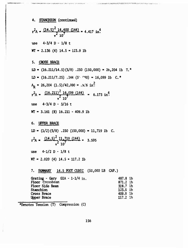
#?<SWöt',Waa!WW»-. ■ ■*• ^tvmy^imK-avt^i^'^r-.^^^ liawrgiwl—iAO' .^WWHWWW «»■r.*^*<>ii1.iw ■ - ■ .Jv^yw.i-(Ar*ittMWf>i(rt^s??!'»J>i«^w^9>^^X^
4. STANCHION Ccontinued]
r2A - (14.5)2 14,400 (144) . 4>417 ^4
IT lO7
use 4-3/4 D - 1/8 t
WT - 2.136 (4) 14.5 » 123.9 1b
5. CROSS BRACE
LD - (16.211/14.5)C5/8) .250 CISO.OOO) = 26,204 lb T.*
LD - (16.211/7.25) .144 (5' ^^O) = 16,099 1b C*
Aj^ - 26,204 (1.5)/42,000 = .y:6 in2.
r2A . (16.211)2 16 099 (144) B 6>173 ^4
use 4-3/4 D - 3/16 t
WT » 3.161 (8) 16.211 - 409.9 1b
6. UPPER BRACE
LD - (1/2) (5/8) .250 (150,000) - 11,719 lb C.
A- (14.5)2 llf719 (144) . 3595
iT IO7
use 4-1/2 D - 1/8 t
WT - 2.020 (4) 14.5 - 117.2 1b
7. SUMHARy 14.5 FOOT CUBIC (50,000 LB CAP.)
Grating - Gary GIA - 1-1/4 in. 487.8 lb Floor Crossbeam 871.2 lb Floor Side Beam 318.7 lb Stanchion 123.9 lb Cross Brace 409.9 lb Upper Brace 117.2 lb
*Denotes Tension (T) Compression (C)
156
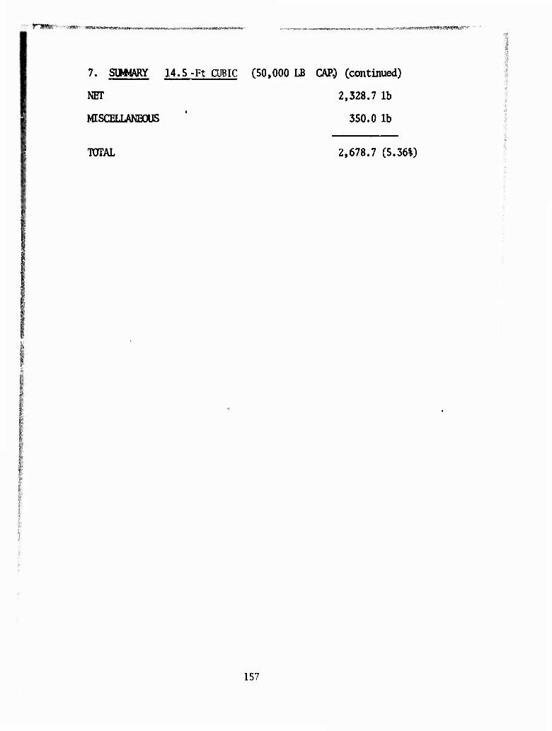
■■f.. IM ^ ■■■.■...,.■..■—.,- «^.v.» .m,mmmml«l.Jl«W«IIMUIWHl>^"
7. SUMMARY 14.5-Ft CUBIC (50,000 LB CAP.) Ccontinued)
NET 2,328.7 lb
MISCELLANBOUS * 350.0 lb
TOTAL 2,678.7 (5.36%)
157
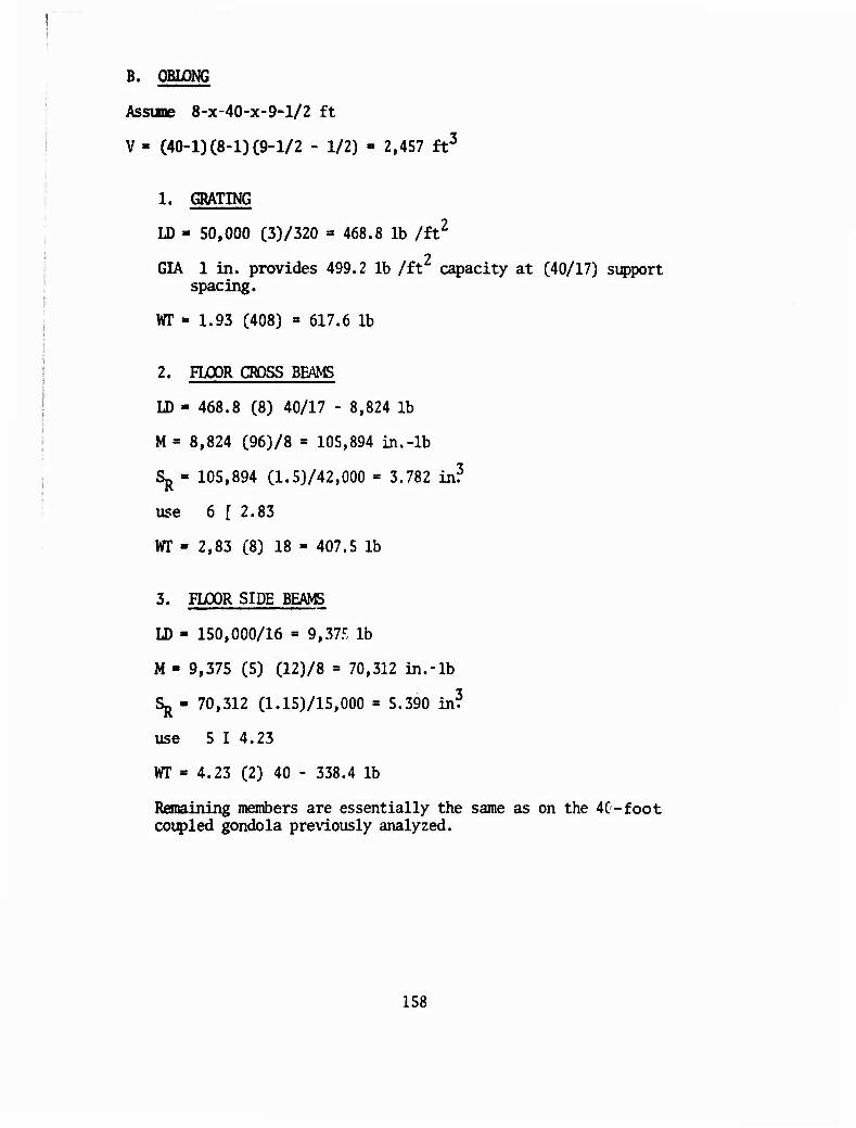
B. OBLONG
Assune 8-x-40-x-9-l/2 ft
V- (40-1)C8-1)(9-1/2 - 1/2) - 2,457 ft3
1. GRATING
LD - 50,000 (3)/320 = 468.8 lb /£t2
GIA 1 in. provides 499.2 lb /ft2 capacity at (40/17) support spacing.
WT - 1.93 (408) = 617.6 lb
2. FLOOR CROSS BEAMS
LD - 468.8 (8) 40/17 - 8,824 lb
M = 8,824 (96)/8 = 105,894 in.-lb
Sj^ 105,894 (1.5)/42,000 = 3.782 in?
use 6 [ 2.83
WT « 2,83 (8) 18 = 407.5 lb
3. FLOOR SIDE BEAMS
LD - 150,000/16 « 9,37.,:, lb
M - 9,375 (5) (12)/8 = 70,312 in.-lb
Sj^- 70,312 (1.15)/15,000 = 5.390 in?
use 5 I 4.23
VT « 4.23 (2) 40 - 338.4 lb
Remaining members are essentially the same as on the 40-foot coupled gondola previously analyzed.
158
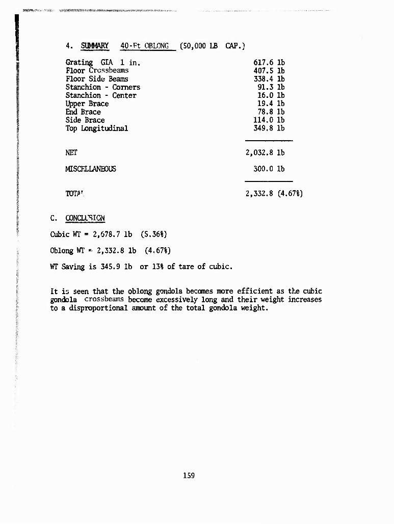
WW»jf:r**>'/V,-W>- ^^«ftflWWt^^^j^
4. SIMIARY 40-Ft OBLONG (50,000 LB CAP.)
Grating GIA 1 in. Floor Crossbeams Floor Side Beams Stanchion - Comers Stanchion - Center Upper Brace End Brace Side Brace Top Longitudinal
NET
MISCRLLANBOUS
T0TAT
C. OONCLUSIGN
Cubic WT = 2,678.7 lb (5.36%)
Oblong VT '■ 2,332.8 lb (4.67%)
WT Saving is 345.9 lb or 13% of tare of cubic.
It is seen that the oblong gondola becomes more efficient as the cubic gondola crossbeams become excessively long and their weight increases to a disproportional amount of the total gondola weight.
617.6 lb 407.5 lb 338.4 lb 91.3 lb 16.0 lb 19.4 lb 78.8 lb
114.0 lb 349.8 lb
2,032.8 lb
300.0 lb
2,332.8 (4.67%)
159
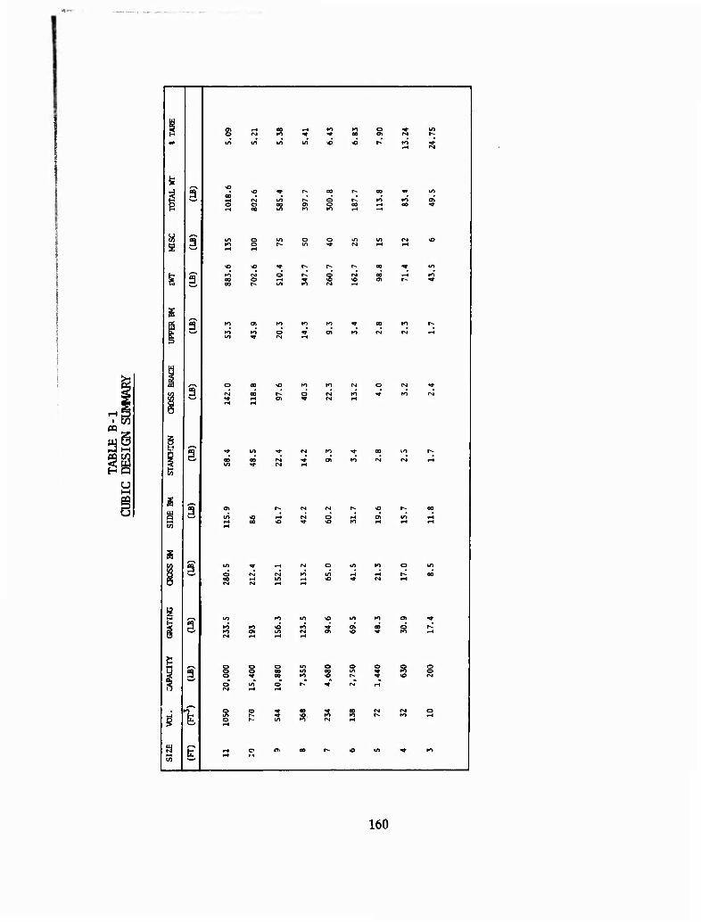
a
9
a
3
f~* f-i
•H N
O >-l
tH Oi
<M r-i
t-t r^
OO i-l
K> ^
S R •O PH
160
APPENDIX C 3URVEY OF TEOWJLOGY
A survey of technology was conducted throughout Tasks A and B of the study program for Phase I. This survey included a review of pertinent reports and technical manuals, and letter interviews with commercial helicopter operators and suppliers of pallets and external cargo hardware. Perform- ance parameters of stability and dynamic load factors together with the logistic and technical requirements were obtained from the reports and technical manuals and bulletins. The survey of commercial helicopter op- erators and pallet gondola suppliers revealed that few helicopters are in use with the capability of the CH-47, CH-54, and HLH. Virtually no pallet or gondola is specifically designed for helicopter external transport.
Pallets/Gondola Equipment
Availability of pallets/gondolas used for external cargo application is extremely limited. As a result, little pertinent design or performance information is available. However, a pallet/gondola system was recently designed, fabricated, and tested to transport the AN/TPN (PAR, ASR, and OPS/B). This system incorporated several design features which are directly applicable to the performance criteria established.
Pallet suppliers' data is shown in Table C-l. Similarly, the response of the helicopter operators is shown in Table C-2.
Evaluation of the data obtained during our technology survey reveals that little or no attention has been given to cargo pallets/gondolas for ex- ternal transport by helicopter. A contributing factor, of course, is the limited usage of large cargo helicopters in commercial applic.tions. Similarly, the more recent application of the CH-47 and CH-54 in trans- porting external loads was hampered by the lack of suitable break bulk cargo carrying equipment. Therefore, the impetus to develop such equip- ment was restricted. The response to the letters of inquiry to pallet manufacturers was minimal. Those that did respond had virtually nothing to offer in satisfying the performance requirements. However, some design features and materials utilized in present pallet technology may be appli- cable to the anticipated design concepts. In genera], the pallets were payload limited, cube limited, and without provisions for helicopter lift- ing as external loads. It was determined that one gondola used in off- shore resupply of Canadian villages was transported by a CH-54 helicopter. This gondola, rectangular in shape, was compatible with ship container cells and could be attached for external cargo transport by helicopter. However, the tare weight was approximately 20% of payload. This pallet/ gondola together with the AN/TPN System had design features which could satisfy some of the performance criteria. A summary of the pallet/gondola survey is shown in Table C-l.
161
i
Physical Characteristics
Evaluation of the physical characteristics of pallets/gondolas was limited by the response of the manufacturers and the fact that pallets/gondolas designed specifically for external helicopter transport are virtually non- existent. Various types of construction were used, ranging from molded plastic to welded/riveted aluminum and steel. One and possibly two of the pallet/gondolas reviewed considered the high vertical load factors and/or the dynamic loading that would be experienced in continued usage. Two of the designs provided lift points above the load center of gravity. These load points had secondary supports and provided a compressive load side member which would be required on long pallets. Most of the pallets were strictly load bearing with little provision for multimodal transport- ability. The material incorporated in the various designs utilized alum- inum more than any other. Aluminum offers good strength-to-weight ratios and cost-strength to weight is likewise good. However, some aircraft quality alloy steels may be more desirable in reducing tare weight. Methods of joining the main structural members of all the pallets were invariably welding, bolting, or riveting the connections. While welding offers de- sirable repairability, the heat-affected zone 01 high-strength alloys would be compromised. Therefore, it appears that the use of standard mechanical fasteners may be preferred. Experience in repairing pallets and that of the maritime industry on containers, it is suggested that the use of sheet stock It avoided where possible. <kie to rough handling environments which are inherent in cargo transport, it is suggested that rugged structural shapes be utilized to the maximum ex cent. Additionally, the joining of sheet stock by adhesive bonding either t" sandwich cores or to structural members is susceptible to corrosive degradation resulting in delaminations which are difficult to repair even at depot levels. While bonded struc- tures are not excluded, their application would be restricted due to the impediments imposed by their use with sheet stock.
Logistical/Technical Requirements
The pallet/gondola survey indicated that all the pallets satisfied one or more of the logistical/technical mission requirements, but no single one satisfied all. Mission suitability of the existing designs was only coin- cidental to a particular feature. Consideration for cargo restraint attachment to the helicopter and rigging was almost universally ignored. Invariably, the designs were directed toward transporting definite loads peculiar to one application. However, the load bearing pallets did per- mit ease of loading/unloading, and cargo could be secured by straps. Equipment interface with regard to interchangeability was incorporated on the AN/TPN pallet set. However, this was restricted to removable secondary structural members. This same pallet utilized standard AN, MAS, and MS hardware for mechanical fasteners, etc. Sufficient design data was not obtained from other manufacturers to assess interchangeability and standard hardware.
162
Some of the pallets incorporated recessed tie-down restraints, while others had restraints only at the edges. Most of the pallets surveyed had flush floor carfices, which is undesirable from two points: (1) the empty return is hampered by large flat plate drag which induces oscillation, and (2) a nonporous floor surface restricts lashing and tie-down. The ERC pallet is a simple X-braced rectangular frame which is desirable for porosity; how- ever, some rigid grating would be required to prevent small object fallout. An additional desirable feature of this pallet is its payload-to-tare weight ratio, which appears to be quite low. Since most of the pallets were designed for load bearing and forklift transportability, little design consideration was given to the higher section modulus induced by sling attachment at the pallet comers above the CG. This requirement, together with the higher load factors, suggests that elevated side and end members be used to provide the desired section modulus. This design feature was incorporated on two of the pallets surveyed.
Personnel effectiveness on most of the pallets was acceptable except the pallets that restricted loading/unloading by nonremovable side or end supports. Additionally, some of the designs had no forklift tineways, which are necessary fron our study. Lack of sufficient tie-down restraints was similarly observed. In instances where hardware was removable, it was not of a captivated nature to minimize losses. These deficiencies must be minimized to the maximum extent to meet the operational suitability and maintainability. Maintainability/repairability must be incorporated in the ruggedness of design to permit a level of misuse that the equipment will experience as demonstrated by container damage history. The pallet/ gondola and container designs observed were invariably lacking in this design characteristic. As a result, the pallet/gondola maintainability/ repairability will be dictated by ruggedness of the design. Ruggedness of the design could satisfy handling environment and load spectrum (ul- timate load factors and dynamic loads), but must minimize tare weight. Therefore, the maintainability/repairability may be satisfied by the judicious placement of rugged members to take maximum advantage of their strength and section properties.
Application of Commercial Pallets/Gondolas
Application of commerically available pallets and gondolas to satisfy the performance requirements of the study was not determined. However, the adaptability of some features for utilizirg load-bearing pallets appears feasible. Of particular interest was the utilization of the standard 48-x- 40-in. load bearing pallet in a gondola frame. Although this concept induces a 200- to 500-lb weight penalty, it utilizes the pallets as both a prepackaging device and a continuous floor for bulk cargo. Additionally, the relatively inexpensive pallet permits forklift unloading or manual unloading. It is further anticipated that the 463L pallet could be util- ized as a slave unit when transporting the gondola by fixed wing as internal cargo. A listing of various types of pallets/gondolas is presented in Table C-l.
163
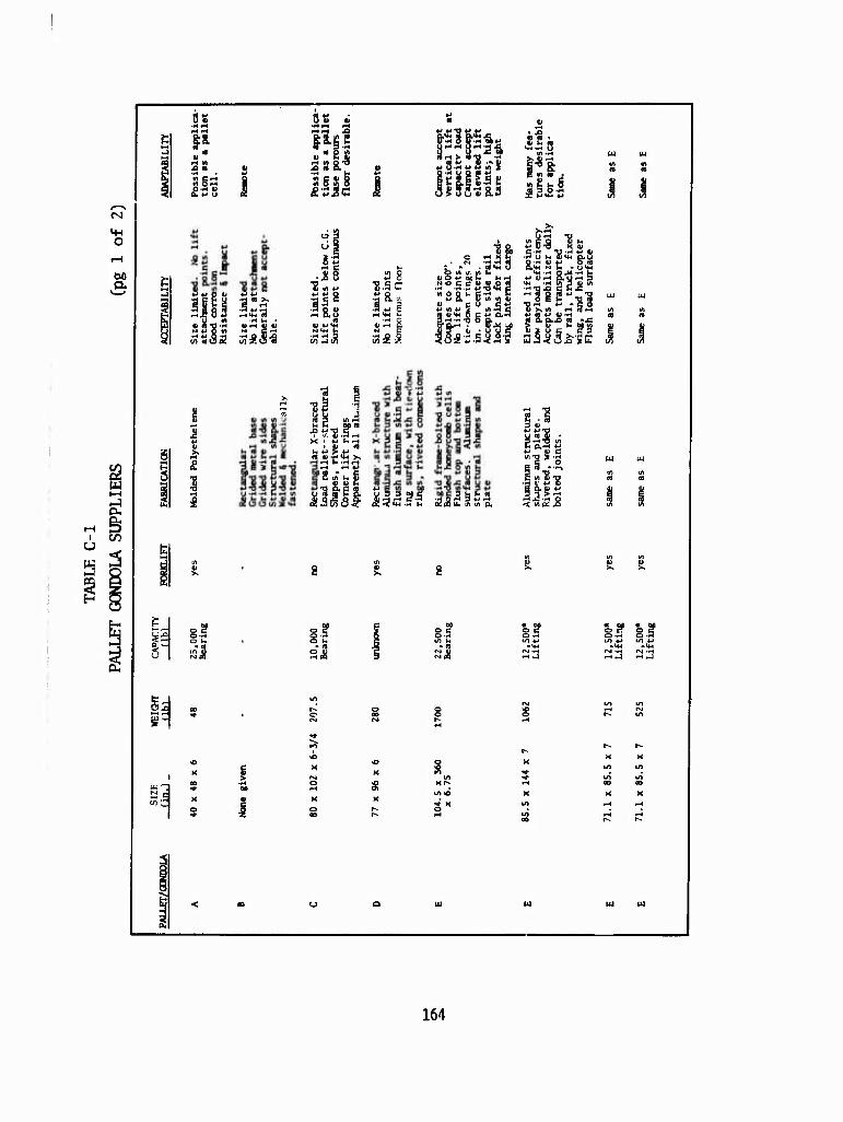
VW o
a
w -3 0-
rH S 1 m u
s S ^ y
3
1 [
3« •H rH
W) 5 r-t £.H U
W «J Ö 4» *-» *>
■H i Q § -S *-• IH
y_ w -HI
I I
^
«2 K
tf) C V Q in 5 w O
8.! o »-
K o
1 > u u t> 8.2
Ji.S3 in 'H
ÜJ S b o I I
3.S iw 0
■8.SC
N C
cu c*; "tjrH *J"2o
! 5 g.
3 §
S in h S
Ü 9 d C S, iil.rl '. «5 g ^ * (2(2 U. in tn p.
»-* «3 rH
hum lm*u I I
p u u n) £ • C 0,rH 4-» *-•_ « c
C irt « -ö
< tn ix JS
15 I? O -H OS LA 4-*
• *+-. rsi -H
r- r-
164
?!WiaK»!«W»i1Wft«»WW;sw>» »i»«« «■TW»*!« ^ -««"ft*;' r n
O
00
g
'J. c
g 6- 6 g »"« « 13 ■SCC
in -o u o B jj «x i«*-» «a 4) -H «J sJ 43 OÄ-O • TJ <n a «>
af-H+JriUiQa. tn->-täUCÜ9'H4) X) O 4* fl Ü <« £ •-, Q • O 3 --H X) Dö
U iH V) C C P a; o u. U 4> t*
1 V P l *-» u
U i o v N !T d w 5 M o ■-< c Q
t/) u u. •-< o
•5-§ « <-< m
§o5S I sl §■311
•ai UJ u, ^
165
Of the pallets/gondolas listed, two types warrant evaluation of particular features: gondolas having elevated load points and gondolas having upper support structure. A synoptic evaluation of their features is presented on the following pages.
The Type E pallet had the following features:
ADVANTAGES
Elevated Load Attachment Points Removable End Supports With Interchangeability Forklift Tineways Towing/Skid Eyes Shock-Absorbing Skid Couplea Sections Captivated and Standard Hardware
DISADVAKTAGES
High Tare Weight Nonporous Floor Area Limited Cargo Restraint Monmovable Siderails Light Weight Edge Members Cube Limited Fixed Lift Points
The Type F gondola was evaluated as follows:
ADVANTAGES
Cubic Capacity Removable End and Side Support Extendable Comer Post Multimodal Transportability Rugged Construction ANSI/ISO Comer Fittings
DISADVANTAGES
High Tare Weight Edge Tie-Downs Only No Forklift Ways Nonporous Floor Weight Lrnited
166
. -. .. fjUfifW**1**
Sufficient design detail was not available on the Type F gondola to con-r duct a thorough evaluation. The Type E pallet, which carried delicate radar equipment, had unique requirements which imposed weight penalties for shock attenuation beyond that required for a general-purpose pallet/ gondola. As reflected from our inquiries, no known hardware embodies the design optimization required for the intensive use of pallets/gondolas as external cargo.
Containers
Containers and their perfonnance present certain criteria that are appli- cable to the pallet/gondola concept. Although the container incorporates many design features not required for pallets/gondolas, several character- istics are analogous. Such attributes as ruggedness, corrosion resistance, and arctic weather operation are applicable. Vulnerability to damage, especially to the floor/base members, is closely related to that of a gondola and end and side supports to the walls of the container. One of the principal causes of failure was handling damage occurring in the base structure. The member most prone to this damage is the lateral edge member. This fact will, of course, be significant in the pallet/gondola design which, in at least some concepts, will utilize this member as a primary structural load path. Damage to these members is experienced from forklift tine impact and in some instances failure through stress concentrations caused by fastener locations.
Although the container design constraints do not address the performance requirements of helicopter transport specifically, such interfaces in terminal handling and intermodal transportability are similar.
■■■•
Commercial Helicopter Operator Survey
A survey of commercial helicopter operators was conducted to determine their critique in transporting external cargo. It is unfortunate that few commercial operators have helicopters with the external payload cap- ability of the CH-47, CH-54, or HIÜ. However, the data supplied by the operators generally corroborates operational characteristics experienced by the military. Although the data is limited, the overall response reflects trends which are consistent with the study parameters. A cor- roboration is presented by the area density (Ap) of the cargo and the flight speed reported. Where flight speeds were reported to be above 60 knots, the load area density was medium. Similarly, where low area den- sity loads were flown, flight speeds of 40 knots were reported. The nominal trip length appears to be 25 miles or less with occasional trips to 80 miles and in some instances short shuttle lengths under a mile.
Rigging and hookup are generally accomplished in less than 30 minutes and 1 minute respectively. These times appear reasonable for the rela- tively small loads transported. The single operator flying the S-64 helicopter reported a low rigging time compared to the smaller loads carried by other operators. Several operators expressed their desire of
167
■iJWWMWWÄiftiNWÄM^WVV^^ *■'
a gondola, although one operator thought they would be dangerous. While few specific conclusions can be drawn from the limited data, trends appear to support other sources with respect to cargo density, area density, and flight speeds. Data from inquiries made to commercial operators is pre- sented in the following table.
168
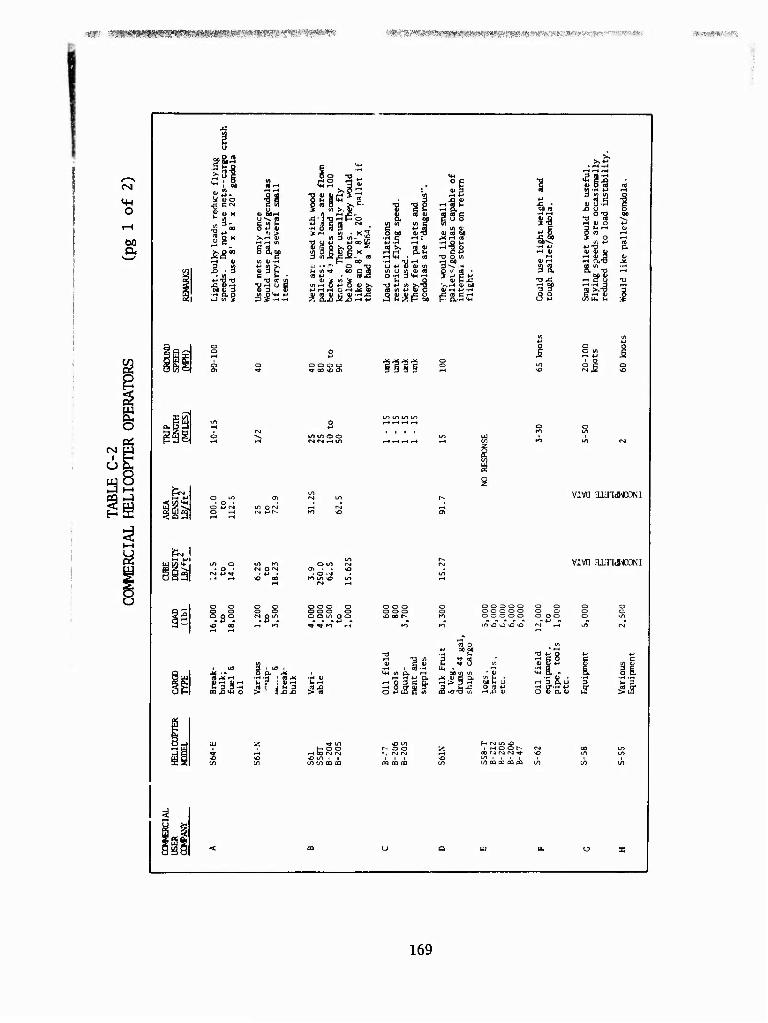
■ ■r .•^riffl^fW^^P^SiSist*«^««»^**'^»)»^^ '?8i?!liWJW89i8^(B(8!(9j?f!j((^^^ ■■ - -WKifimyfVK
O
00
l?l lM . nil
as C CM
g « X
1*- ggx
I J 111 ■H ao
li C (A M O »J ft)
o au
-a re «
Ö o -o
iiilix» } •- -^ o -q ■• (/) TT CO £ m
i« o *3 6 oi >s
|1 1 W1 I/)
3§
U ♦-' tt) '■ tf) u a < OH 3*-
(d O v~ t4 _Q ft* P J
5£ÄiS:
1111
! ft) 00
a«
1
d be u
sefi
occa
sion
* ad instab
(4
¥^ *-> o ft)
p re ^2 ■a-?1
CO ■H 4-*
11,1 ♦H ft>
,* 3S. 5^1 13 x: 13
o *-• 8 2
^ LO ^ *> o Ul Oi (VI in
la o S^ in O rvi rs o *-»!-- Kl v£>
&V LO lil o Kl O LO r^j
o • O f^ en . . <£) s ^ rsj *-> ^r *-* • . O -M Q -4 r-t •o ao K) U1 «O LA
O o o o oo o O O O O
9 S O o o Q o o o O o o o o o o (^ 8"! o o tn O O o oo r-
*J - +•> a — sD 00 rt
Kl ■t *t Kl r-t Kl
vivn anndnxwi
viva njjidNCDNi
O O 3 O O o o o o o o o o o o in o o ^> •£>
(5 j< r .
00,01+4 0 >
3 ,K o a 5^
^H 13 tfl
5^J
i 1 IM * H *J i 3 C
'.SU E 3t
ft) fie
pme
, t 1 iR
to r^ 3 a u 3 w 3 5ti ir ^ff
*o "1 ^H 00 I^J CM
1^ o o ■v r^rj
vo in < i tow m CQ CQ CQ CO
H c-) ui * . ^ O O i--
oo CJ r^j r-i ^■ in > i i i tn ca aa CQ pa
169
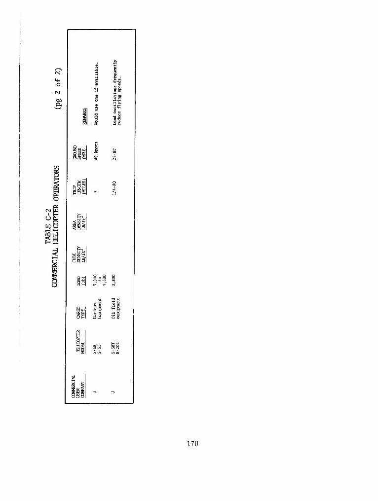
O rsi
60
m
&.
\n
u
i SI ■H X u C
31 o *
oo o
170
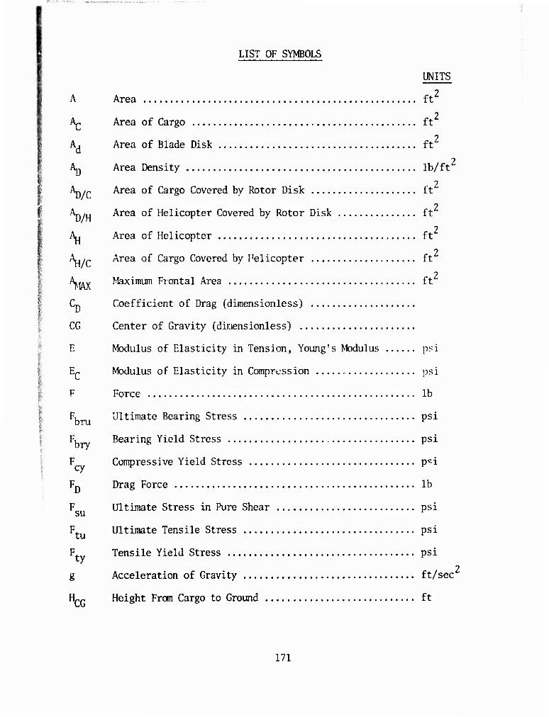
:
LIST OF SYMBOLS
UNITS
A Area ft2
7 Ap Area of Cargo ft
Ad Area of Blade Disk ft2
2 Ay Area Density lb/ft
2 \)/C ^rea 0^ ^ar80 Covered by Rotor Disk ft
An ,„ Area of Helicopter Covered by Rotor Disk ft 2
A, Area of Helicopter ft 2
X,/r Area of Cargo Covered by Helicopter ft 2
Law Maximum Frontal Area ft
Cp. Coefficient of Drag (dimensioniess)
CG Center of Gravity (dimensioniess)
E Modulus of Elasticity in Tension, Young's Modulus psi
E- Modulus of Elasticity in Compression psi
F Force lb
F. Ultimate Bearing Stress psi
Fu Bearing Yield Stress psi
F Compressive Yield Stress pci cy r r
Fn Drag Force lb
F Ultimate Stress in Pure Shear psi
F. Ultimate Tensile Stress psi
F Tensile Yield Stress psi ^y 2
g Acceleration of Gravity ft/sec
HCG Height From Cargo to Ground ft
171
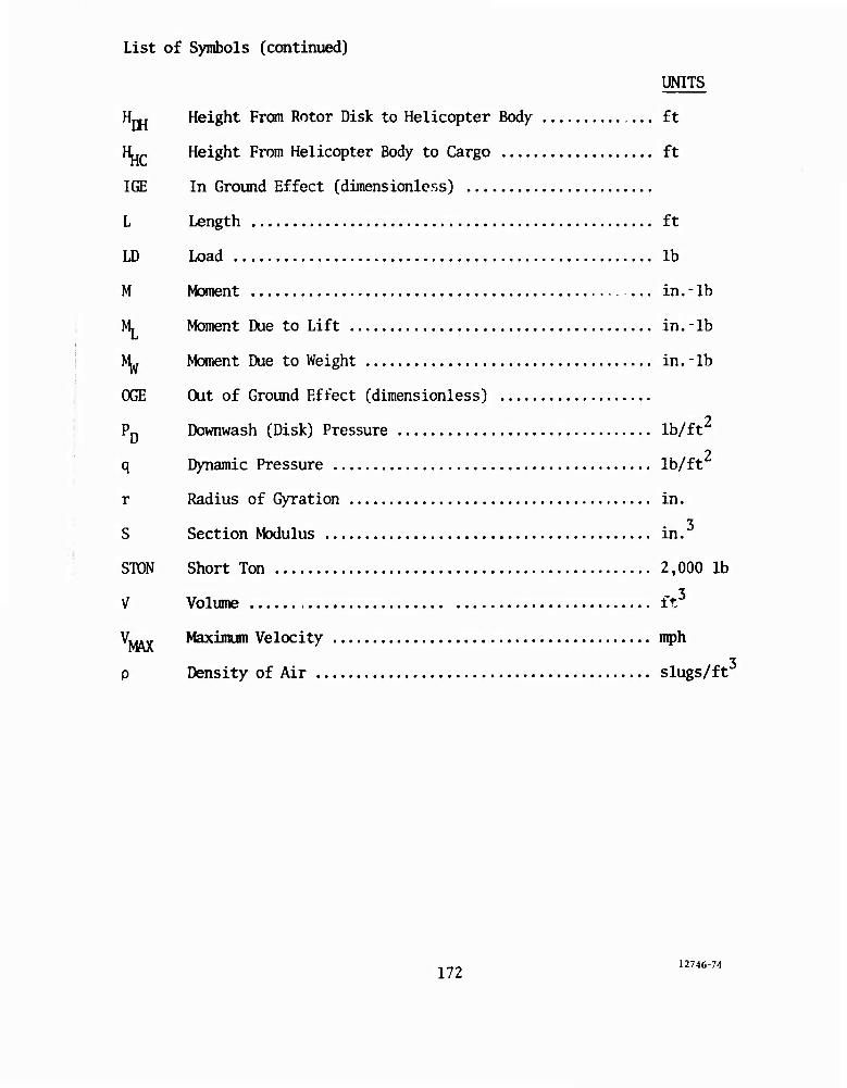
List of Symbols (continued)
UNITS
H~. Height From Rotor Disk to Helicopter Body ft
Hup Height From Helicopter Body to Cargo ft
IGE In Ground Effect (dimensionless)
L Length ft
ID Load lb
M Moment ... in. - lb
M, Moment Due to Lift in. - lb
NL Moment Due to Weight in. - lb
OGE Out of Ground Effect (dimensionless)
2
2
PD Downwash (Disk) Pressure lb/ft^
q Dynamic Pressure lb/ft
r Radius of Gyration in.
S Section Modulus in.
STON Short Ton 2,000 lb
V Volume ft3
Vw^ Maximum Velocity mph
p Density of Air slugs/ft
172 12746-74