Embed Size (px)
Citation preview
AD/A-002 342
SYSTEM CERTIFICATION PROCEDURES ANDCRITERIA MANUAL FOR DEEP SUBMERGENCESYSTEMS
Naval Material CommandWashington, D. C.
July 1973
I f/,
DISTRIBUTED BY:
National Technical Information ServiceU. S. DEPARTMENT OF COMMERCE
Id
NAVMAT P-9290July 1973
SYSTEM CERTIFICATION PROCEDURES
AND CRITERIA MANUAL
FOR
DEEP SUBMERGENCE SYSTEMSOF
DD G
FTRINr. N .22 1974
NAVAL MATERIAL COMMAND
NAVAL SHIP SYSTEMS COMMAND
NAVAL FACILITIES ENGINEERING COMMAND
DEPARTMENT OF THE NAVY D(STi-,tITIONS.., MENT . .WASHINGTON, D.C. 20362 Atwvoyg for outhttcreo, t
[ itxi-Ui~n Unhitad-
This document has been approved for public release and sale. Its distribution Is unlimited.
RIproduced by
NATIONAL TECHNICALINFORMATION SERVICE I
US Dprn ol Comm me
Vploli,'A. 22151
magam-.- di
RECORD OF CHANGES / 2 /).k. "-
Page Date of Change Date Entered By Whom Entered
.... .. ij,.i
I ........... .... . . . ..
BY
DIV, L IAIL. a,!9, o L ._._
I -'
I
/!
4!
i I
IiI
-71
FOREWORD
Through the Chain of Command, the Naval Ship Systems Command (NAVSHIPS) andthe Naval Facilities Engineering Command (NAVFAC) have been assigned respons,'litiesfor the development, promulgation, and implementation of procedures and criteria bywhich personnel safety of manned non-combatant Deep Submergence System (DSS) is to beevaluated. NAVSHIPS has certification responsibilities for shipboard systems andNAVFAC for shore based systems. These procedures and criteria were known as theMaterial Certification process.
Experience has shown that the word "Material" when used in conjunction with certi-fication tended to place undue emphasis on traceability and chemical analysis of individualsystem components to the exclusion of other equally important certification supportiveprocedures. -While traceability and chemical analysis are important, other methods ofsafety assurance must also be used to satisfy the Certification process. For example,design interrelationships of components as a system, fabrication techniques and prooftesting must also be evaluated by the Certification Authority. Therefore, to avoid con-fusion, the term "Material Certification" has been replaced by the term "SystemCertification."
The knowledge contained herein is the result of a combined effort by the Naval ShipSystems Command and the Naval Facilities Engineering Command and presents a viableset of guidelines through which the designer and/or builder of submersibles, :n or onbottom habitats, diving systems, hyperbaric facilities, and attendant handling systemscan gain maximum reasonable assurance that the lives and well being of Naval personnel
4 Iusing these deep submergence systems will be safely preserved. These System Certifi-cation guidelines are not intended to provide rigid procedures for construction or tostifle initiative and innovation in the use of new methods, components, systems ormaterials.
This manual supersedes the following individual publications:
A. "Hyperbaric Facilities, General Requirements for MaterialCertification," Naval Ship Systems Command - Naval FacilitiesEngineering Command, Department of the Navy, Washington, D.C.NAVSHIS 0994-007-7010, NAVFAC P-422, May 1970.
B. "Material Certification Procedures and Criteria M\Ianual forManned Non-Combatant Submersibles, " Naval Ship SystemsCommand, Department of the Navy, Washington, D. C.NAVSHIPS 0900-028-2010, September 1968.
C. "Diver Equipment, General Requirements for Material Certification,"Naval Ship Systems Command, Department of the Navy,Washington, D.C. NAVSHIPS 0994-01.2-3010, June 1971.
Custodianship and responsibility for maintaining the technical content of this manualto meet the Navy's needs rests with the Naval Ship Systems Command who will consultwlth the naal Facilitie Ejgireering Command concerning their areas of responsibilityprior to issuing changes. Changes and/or recommendations to improve the content ofthis booklet should be directed to NAVSHIPS OOC, Washington, D. C. 20362.
i 1i1
Certification of this publication as an official command publication has been reviewedand approved in accordance with the Secretary of the Navy Instruction 5600.16.
Chief of Naval Materi
iv
TABLE OF CONTENTS
CHAPTER PAGE
I GENERAL INFORMATION
1.1 Introduction 1-1
1.2 Glossary of Terms 1-3
1.3 Purpose 1-8
1.4 Applicability 1-8
1.5 System Certification Procedure 1-10
II SYSTEM CERTIFICATION SCOPE
2.1 Introduction 2--
2.2 System Certification Scope 2-1
2.3 Definition of System Certification Scope 2-1
2.4 Examples of Areas of a DSS Involved inSystem Certification 2-2
2.5 Pre-Survey Outline Booklet (PSOB) 2-3
III DESIGN
3.1 Introduction ,-1
3.2 Recordable Evidence 3-1
3.3 Design Review Information 3-2
IV CONSTRUCTION, FABRICATION, AND ASSEMBLY
4.1 Introduction 4-1
4.2 Recordable Evidence 4-1
4.3 Construction and Fabrication ProcessRequirements 4-1
V
II
TABLE OF CONTENTS Continued
CHAPTER PAGE
V QUALITY ASSURANCE
5.1 Introduction 5-1
5.2 Quality Assurance Provisions 5-1
5.3 Drawing Control 5-2
5.4 Material Control 5-2
5.5 Fabrication, Manufacturing and Dimen-sional Control 5-2
5.6 Testing and Inspection Control 5-2
5.7 Workmanship 5-2
5.8 Quality Assurance Information 5-3
VI TESTING
6.1 Introduction 6-1
6.2 General Requirements for Operationaland Proof Tests 6-1
6.3 Proof, Pre-Builder or Pre-Sea Trial .,'ests 6-2
6.4 Builder's or Sea-Trials 6-4/
6.5 Operational Tests of Diver Equipment 6-5
VII OPERABILITY AND MAINTAINABILITY
7.1 Introduction 7-1
7.2 Requirements 7-1
7.3 Demonstrations 7-1
7.4 Operating Manual 7-1
7.5 Maintenance Manual 7-3
vi
K>!-. 1
TABLE OF CONTENTS Continued
CHAPTER PAGE
VIII ON-SITE SURVEY OF DSS
8.1 Introduction 8-1
8.2 Survey Team Perscnnel 8-1
8.3 Survey Procedures 8-1
IX SYSTEM CERTIFICATION APPLICATION
9.1 Introduction 9-i
9.2 Application 9-1
x TENURE OF SYSTEM CERTIFICATION
10.1 Introduction 10-i
10.2 Sustaining System Certification 10-1
10.3 Continuance of System Certification 10-2
10.4 Recertification 10-2
APPENDIX
A CATEGORIZATION OF CERTIFICATION SCOPEMATERIALS AND COMPONENTS
A. 1 Introduction A-1
A.2 Category 1 A-1
A.3 Category 2 A-2
A. 4 Category 3 A-5
B DESIGN PARAMETERS FOR DEEP SUBMERGENCE
SYSTEMS
B. 1 Introduction B-i
B. 2 Design of Pressure Hull/Vessei, HardStructure and Piping Systems B-1
vii
_ -
TABLE OF CONTENTS Continued
APPENDIX PAGE
B. 3 Fabrication Design Criteria B-13
B. 4 General Requirements for Design of LifeSupport Systems B-15
B. 5 Toxic and Flammable Material DesignConsiderations B-25
B. 6 Design of Control Systems, Electrical PowerDistribution Systems and Lighting Systems B-26
B. 7 Naval Architecture Design General Require-ments B-31
C DESIGN PARAMETERS FOR IMPLODABLE ITEMS
C. 1 Introduction C-I
C. 2 Definitions C-i
C. 3 Distinguishing Critical and Non-CriticalVolumes C-1
C. 4 Testing Necessary for "Critical Volumes" C-3
D DESIGN PARAMETERS FOR EXPLODABLE ITEMS
D. 1 Introduction D-1
/ D. 2 Description and Orientation D-1
D. 3 Procedure D-1
D. 4 Non-Metallic Materials D-2
E DEEP SUBMERGENCE SYSTEMS BREATHING
GAS REQUIREMENTS
E.1 Introduction E-1
E. 2 Breathing Gas Consumption E-1
E. 3 Surface Breathing Air Requirements E-7
viii
--J !
TABLE OF -CONTENTS Continued
APPENDIX PAGE
E. 4 Compressed Breathing Air Requirements E-I1
E. 5 Hyperbaric Breathing Gas Requirements E-14
F GENERAL GUIDELINES FOR ATMOSPHERICEVALUATION OF MANNED DSS
F. I Introduction F-1
F.2 Sampling Apparatus and Procedures F-1
F. 3 Analytical Procedures F-2
F. 4 Atmosphere Evaluation Procedures F-4
F. 5 Additional Discussion About Chlorocarbons F-6
F. 6 Interpretation and Application of the Data F-6
G GENERAL GUIDELINES FOR CLEANINGBREATHING GAS SYSTEMS
G. 1 Introduction G-1
G.2 References G-1
G. 3 Definitions G-2
G. 4 General Procedures G-2-/G. 5 Cleaning Methods and Materials G-3
G. 6 Sampling and Analyzing G-6
G. 7 Cleanliness G-9
G. 8 Maintaining the System in a Clean Condition G-12
H GENERAL GUIDELINES FCON DSS HANDLING
SYSTEMS
H. i Introduction H-1
H. 2 Definitions H-1
ix
TABLE OF CONTENTS Continued
APPENDLC PAGE
H. 3 Design Criteria H-1
H. 4 Verification of Adequacy 1--4
J BIBLIOGRAPHY J-1
It
/I
/
X.
LIST OF ILLUSTRATIONS
FIGURENUMBER PAGE
1.1 Flow Chart, System Certification Milestone Events 1-12
B. 1 Standard Minimum Inspired Gas Temperatures B-24
C. 1 Minimum Standoff Distance for Implodable Items(Spherical Pressure Hull) C-4
C. 2 Sample Calculation (Assume Spherical DSS Has6000 Ft. Maximum Design Depth) C-5
E. 1 Relation of Respiratory Volume and Oxygen Con-sumption to Type and Level of Exertion E-2
E.2 Relation of Physiological Effects to Carbon DioxideConcentration and Exposure Period E-6
E.3 Percentage of Oxygen in Breathing Mixture as.aFunction of Depth and Oxygen Partial Pressure E-10
E. 4 Relation of CO Tolerance Zones to Depth andPercentage of C02 in Breathing Gas E-14
LIST OF TABLES
TABLENUMBER
E-1 Effects of Various 02 Concentrations E-4
E-2 Limits for Atmosphoric Constituents(Limits in PPM by Volume Unless Otherwise Noted) E-7
E-3 Time Limits for Working Dives, as Influenced byOxygen Partial Pressure and Type of BreathingEquipment E-11
G-1 Cleanliness Requirements G-11
G-2 Fiber Length Limits by Cleanliness Level G-11
* H-i Minimum Values of Factor of Safety H-3
X-1
CHAPTER I
GENERAL INFORMATION
1.1 INTRODUCTION
This Manual is presented as a set of guidelines for the desiger and/or builder ofa Manned Deep Submergence System (DSS), including any non-combatant subm.rsibie, inor on bottom habitat, diving system, diver equipment or hyperbaric facility, that isinended for Naval use. IT IS NOT INTENDED EITHER TO PROVIDE RIGID PROCEDURESFOR CONSTRUCTION OR TO DISCOURAGE INITIATIVE AND INNOVATION IN THE USEOF NEW METHODS, COMPONENTS, SYSTEMS, AND MATERIALS; NEITHER IS ITINTENDED THAT THIS MANUAL SHOULD BE INVOKED AS A CONTRACTUAL DOCU-MENT. The translation of System Certification criteria and procedures into technicalcontractual specifications is the responsibility of the DSS development program manageror "sponsor.
The objective of the Certification process is to verify that a Deep SubmergenceSystem provides acceptable levels of personnel safety throughout the specified operatingrange of the DSS when used in accordance with approved operating and maintenanceprocedures. The certification process is concerned with establishing maximum reasonableassurance of the recovery of DSS personnel without injury, and the deliberate avoidanceof conditions that imperil the lives and well-being of operating personnel. The certifica-tion of a DSS does not relieve its sponsor from his responsibility to maintain a safe DSSon a continuing basis,
DSS personnel are considered to be the occupants, passengers, divers, pilots,4. etc. The safety of handling system personnel and external DSS equipment operators isnot normally covered by the System Certification process except when the lives and well-
being of DSS personnel would be imperiled. The application of Deep Submergence SystemCcrtification Criteria and Procedures to routine shore and marine industrial safety(otherwise covered by MIL-STD-882, etc.) is not intended.
The principal participants in the System Certification process are: (1) the DeepSubmergence System Sponsor who is applying for or sustaining System Certification; and(2) the System Certification Authority (SCA), NAVSHIPS or NAVFAC, who implements
, the System Certification Process. The Naval Material Command (NAVMAT) maintainscognizance and effects priorities.
The responsibility of the Certification Authority to verify system adequacy, withinthce specified operational limits with respect to personnel safety, extends to the evaluationof the established DSS operation and maintenance procedures.
Mission reliability is of concern to the Certification Authority only as it relatesto the ability of the DSS to effect recovery of DSS personnel without injury.
Effective DSS Certification with a minimum of difficulties is dependent on:
a. Primary Duty Assignment of a 1mowlcdgeable individual to represent thesponsor in the negotiations relative to the certification of the candidate DSS.
1-1
b. A clear understanding of the certification process by the sponsor'srepresentative.
c. A clear understanding of the DSS by the Certification .'uthority.
d. Frequent negotiation between the snonsor and the Certification Authority.
The importance of frequent negotiation (free exchange of information) betweenthe Sponsor and the Certi-fication Authority caL,ot be over-emphasized. Only throughneg-otiations can the Sponsor and the SCA establish a realistic balance between conflictingcost/time reduction objectives and the certification objectives and also only in this waycCLf the Certification Authority gain sufficient kmowledge and understanding of the candidateDSS to permit effective and practical accomplishment of the certification objectives.
A major function of a DSS is to provide an acceptable life supporting environmentof the correct temperature, composition, and pressure. Exceeding the permitted rangesof the various environmental factors could have severe or fatal consequences. In thecase of diver involvement the time required for decompression cannot be reducedsignificantly, even in an emergency. Design criteria are therefore considered whichdirectly concern the safety of personnel.
Specific information on materials and procedures is contained within the appendicesto this manual. Sources of information that the System Certification applicant may findbeneficial are listed in the bibliography included in the appendices.
Blefore proceeding with the contents of this manual, a review of the following"Glossary of Terms" is advisable.
1A/2
1 .'.2
1.2 GLOSSARY OF TERMS
For purposes of this Manual, the following words or phases are as defined:
Accessibility to Vital The ability to reach, readEquipment and/or operate vital equip-
ment and devices.
Accident A happening that is not expected,foreseen, or intended under normalcircumstances.
Alteration A change from the as certifieddesign, material, configuration,or performance.
Applicant/Sponsor The Agency/Organization that is makingapplication for System Certification orRecertification of a DSS. For DSS beingdeveloped, the Applicant/Sponsor willnormally be that Agency/Organizationtasked with development of the capabilitybeing supplied by the DSS. For existingDSS, the Applicant/Sponsor will normallybe that element within the organizationalchain responsible for operational readine.,:and deployment of the specific DSS.
Appurtenances An accessory added to a majorcomponent-(e.g. viewports, hatches,jettisoning equipment, supportI rails, connectors, piping, et al.).
Breathing Gas Supply Equipment Equipment that is used to compress,4condition, mix, store, distribute,
or otherwise handle breathing gas.
Builder Contractor or agency who constructsthe DSS.
Casualty An accident usually resulting inphysical injury to personnel, -and/ordamage or interruption of the normaloperation of the DSS.
Catastrophe Any great or sudden disastrous mal-function which jeopardizes the safetyof the DSS personnel.
Certificate The document attesting to the SystemCertification granted by the SCA.
Certifiable See System Certification.
12. . 1-3
IE
Certification See System Certification.
Certification Scope A list defining those systems, sub-systems, components, portions of theDSS, maintenance and operational pro-cedures which are needed to preservethe physical well-being of the DSSpersonnel. (See Chap. II)
Deep SuLmergence System(s) Any manned, non-combatant submersible,(DSS) in or on-bottom habitat, hyperbaric facil-
ity, deep diving system or diving equipment,including attendant systems, providing orsupporting the ability of naval personnelto operate under water. (See paragraph 1.4)
Diver An individual who is qualified in accord-ande with current Bureau of NavalPersonnel instructions.
Emergency A sudden unexpected malfunction orother set of circumstances in the DSSoperation, which requires immediateattention.
Explodable Items Any item containing a non-compensatedvolume which has the potential forfailure under internal pressure.
Fire R. -. stant A material that will immediately self
extinguish when the source of ignitionis removed, when tested in an atmosphererepresentative of its intended use environment.
Flotation System The materials, tanks, piping, components,or equipment that provide buoyancy to the DSSas may be applicable.
Foundation That permanently installed part of a DSSwhich serves exclusively to support theDSS.
Framing System (See Hull Structure)
Handling System That system or subsystem of the DSSwhich is used in storing, deploying, opera-ting and retrieving the DSS and is intimatelyrelated to safety of DSS personnel.
Hard Structure Pressure resistant structures includingreinforced openings and penetrations, butother than th .. pr.sre ,, , ,hic.h mayexperience high differential pressure andthat are designed to the same criteria asthe pressure vessel. (e.g. buoyancy orvariable ballast tanks)
1-4
Heat Resistant A material that does not give off noxiousfumes at its operating temperature or at anytemperature below 200 degrees Fahrenheitand which is not degraded in respect to per-forming its intended function when exposedto a temperature of 400 degrees Fahrenheitfor 5 minutes.
Hull Structure Non-pressure structure which will notexperience differential pressure, (e.g.floodable structure supporting equipmentand including hydrodynamic fairing). Forshore based facilities the appropriate termis Framing Systems.
hlyperbaric Chamber Pressure-resistant structure, includingpertinent reinforced openings, penetra-tions, and hatches, which experienceshigh differential pressure and which provides
ispace for personnel.
Hyperbaric Facility A complex, for operation at pressuresabove atmospheric, in which the magnitudeand rate of change of the pressure and thecomposition and temperature of the confinedatmosphere and/or water can be accuratelycontrolled.
Implodable Items Any item containing a non-compensatedcompressi'le volume which has thepotential for failure under external pressure.
Life-Support Systems A system that provides a livable environ-ment (see paragraph 2.4.4).
Material Adequacy Designed and constructed of the proper(materially adequate) materials and performance tested in
accordance with accepted engineeringprinciples so as to provide for the safetyof the DSS personnel.
Milestone Event Schedule A lit of sequential events in the certificationprocess with estimated completion dates.
Non-combatant A DSS which, by its design, is incapableof defensive or offensive action in combat.
Occupant(s) Any person occupying the DSS.
Operator(s) 1. The organization, agency, or firmhaving responsibility for the operations,repair and maintenance of the DSS.
2. The personnel who physically controlthe operating parameters of the DSS.
Passenger(s) Any person embarked who is not involvedin primary control of the DSS.
1-5
!.
_.....
Penetration The assembly, component, shaft packinggland, seal, or other device which penetratesthe pressure resistant structure (e.g. pressurevessel or bard structure).
Pressure Vessel See definition of Hyperbaric Chamber.
Pre-Survey Outline A check list that identifies those areasBooklet (PSOB) to be reviewed as part of the certification
procedure for a specific DSS.
Procedural Adequacy The procedures used in the operation andmaintenance of the DSS are suitable andsufficient to provide for the safety of theoccupants and operators of the system,before, during or after any credibleoperational/emergency evolution.
Procedures Instructions, checklists, and maintenanceguides prepared in a manner that providesto the occupants and operators a detailedsafe sequence of operations of the DSS inall its various designed normal andemergency operating modes.
Recordable Evidence All recorded information, including opera-tional and maintenance procedures which canbe used as proof that the DSS has been designed,constructed of the proper materials, fabricated,assembled, and performance tested inaccordance with acceptable engineeringprinciples.
Repair A restoration or replacement to theoriginal condition which does not change theoriginal design material, configuration orperformance, using procedures previouslyapproved.
Replacement-in-Kind Replacement with parts or components meetingoriginal specification requirements.
Scope See Certification Scope.
Sponsor See Applicant/Sponsor.
Submersible Any ship, vessel, capsule or craft capable ofoperating underwater, with or without propul-sion with the operators and/or passengersembarked.
1-6
MW W4_
Survey To examine, inspect and review in detail all
items falling within the certification scope todetermine their material adequacy and pro-cedural adequacy.
Survey Tema The personnel representing the Navy toperform the onsite verification survey ofthe DSS.
System Certification The procedure including application, inde-pendent technical review, survey and ap-proval to insure the adequacy of the DSS tosafely perform over its operational/emergencyspectrum. System certification is a combin-ation of two major areas of review; materialadequacy and procedural adequacy. (Thisreplaces the old term "material certification. ")
System Certification The code within either NAVSHEPS or NAVFAC,Authority (SCA) as applicable, that has been delegated, through
the Navy chain of command, the responsibilityto conduct the Deep Submergence System Cer-tification process.
$
~1-i
j/
1-7, I
1.3 PURPOSr"
The purpose oO this manual is to describe the process for determining that a DSS,on which the lives and well-being of Naval personnel is dependent, is adequate from asafety steidpoint. This process extends to the determination of system adequacy withinthe oper,.tional limits for which certification is being requested. It is not intended torestrict the development or use of new ideas, systems, hardware, or equipment.
The basis for determining the system adequacy of each DSS will be the informationand justification submitted by the Applicant/Sponsor. This manual describes the proce-dures and criteria that will be used by the System Certification Authority and which shouldbe considered by t - Applicant/Sponsor.
1.4 APPLICABII[TY
System Certification is required for any DSS built by the Navy, or built by privateindustry and used by the Navy under contract, and/or built by private industry and sub-sequently purchased by the Navy for use ky Naval personnel. If the lease or charter ofthe DSS does not involve the safety of Naval personnel, the DSS need not be certified bythe Navy.
This manual covers Systern Certification of all types of mantued DSS capable ofoperating with or without propulsion, on and under the surface of the water or land basedwith the operator(s) and/or passengers embarked in a wet or dry environment and which,by its design, is incapable of either defensive or offensive action in combat. Typical ex-amples are grouped as follows:
Groups:
I Man is dry; always at one atmosphere except when in escape trunk
Examples:
(a) Untethered submersibles such as TRIESTE, Deep Submergence RescueVehicle (DSRV), ALVIN, TURTLE, DEEP VIEW, etc.
(b) Tethered chambers such as bathysphere, McCann Submarine RescueChamber, acrylic elevator, etc.
(c) One atmosphere SEABED Habitats.
1I Man is- dry, capability for elevated pressures
Examples:
Hyperbaric chambers, recompression chambers (such as single and double lockrecompression chambers, collapsible recompression chambers), deck decom-pression chanbers, entrance locks, medical chambers, etc.
1-8
III Man is wet: capability for elevated pressures
Examples:
(a) Diving equipment and integrated systems on the man such as hardhat gear,mixed gas scuba (MARK 6, MARK 8, MARK 10, MARK 11, etc.)
(b) Submarine escape apparatus such as Steinke Hood, exposure suits, orother escape breathing apparatus.
I Man is wet or dr-; pressure is elevated
Examples:
(a) Manned underwater habitats such as MAKAI Habitat, SEALAB and TEKTITE.(Tbe habitat may or may not be pressurized as a step in the implantmentevolution, but design is basically for free communication between habitatand the sea.)
(b) Saturation Deep Diving Systems such as DDS MK 1, DDS MK 2, etc.
(c) Shore based hyperbaric facilities such as the Navy Experimental DivingUnit (F'"U) and the Ocean Simulation Facility (OSF) Panama City, Florida.
For each DSS, the basis for System Certification will be the evaluation of the re-cordable evidence submitted by, or in tbe custody of the applicant and such on-site surveysand audits which are deemed necessary b the SCA. The recordable evidence should en-compass the areas of:
(a) Design
(b) Construction, Fabrication and Assembly
(c) Quality Assurance
(d) Testing
(e) Operability
(f) Maintainability
For a new DSS, the assembly and presentation of this recordable evidence to the SCAshould require a mini'mum of time and effort. It is no more than that information normallyexpected to be generated by a prudent designer and builder.
For a new DSS, which is an exact duplicate (e.g., depth limits, temperature, periodof use, environment, etc.) of a certified DSS, an audit of the quality control and testing re-cords and a survey of the DSS may provide sufficient recordable information.
For a DSS already in existence and possibly in service, the assembly of sufficientrecorde e inc. miht require Affort If reeordable informatton is not
ur
1-9
A1
easily recaptur-able, the information may have to be re-created. To re-create recordableevidence, the applicant may have to resort to non-destructive and/or destructive testing,inspection and design review analyses.
Tie criteria noted in this manual will not necessarily cause the System Certification 4
of current tenures to be revoked prior to normal expiration. However, all recertificationshall be judged using the criteria established by this manual.
It must be recognized that information may become available that indicates the.xistor of an unsafe condition which had not been previously identified. In such circum-stances, when the SCA considers the severity of the condition to warrant such action, thedesign of all DSS, either certified or still in the certification process, will be reevaluatedwith respect to the unsafe condition.
1.5 SYSTEM CERTIFICATION PROCEDURE
The Navy activity that desires to lease or purchase an existing commercial DSSfor use by Naval Personnel should inelude system certification requirements for DSS aselements of the contract.
The organization within the Navy that is contracting for the design and/or construc-tion of a DSS should translate system certification criteria and documentation considerations(to support a System Certification Technical Review) into the contract specifications. Theuse of this manual as a contract reference document, with contractor interpretation of re-quirements should be -ivoided. (Note: If a contractor anticipates lease, or purchase bythe Navy, of a DSS he is building, he should become familiar with the documentation re-quirements necessary to support a system certification technical review.)
The Naval Activity utilizing an existing Navy DSS should initiate System CertificationProcedures in accordance with the current OPNAVINST 9290. 2 series, prior to continuingDSS operations.
1.5.1 Procedure
The-System Certification Procedure normally will include the following steps:
(a) The Applicant/Sponsor should prepare a System Certification Application inaccordance with the provisions of Chapter IX which includes the following:
(1) Preparation of a System Certification Scope, as outlined in ChapterII, and a Certification Milestone Event Schedule for negotiation andapproval by the System Certification Authority (SCA). The certifica-tion milestone event schedule should include a list of sequential eventsin the Certification process with estimated dates of completion. Thetime allowance for documentation submittals, technical reviews, anddeficiency corrections should be considered in the milestone eventschedule to assure a timely completion of the certification processprior to the desired use date.
(2) Preparation of a Pre-Survey Outline Booklet (PSOB) based on thesystem certification scope for negotiation and approval by the SCA.The PSOB should be tailored to the particular DSS from *a typicalPSOB format.
1-10
b. The applicant/sponsor will be required to provide funds, based on the SCA's costestimate, to support the documentation review, survey team travel expenses and othercertification related expenses as determired from 'by the scope, PSOB and milestoneevent schedule.
V. The applicant/sponsor should collect the documents that support each line item of*p the P301B, index them to the PSOB line items and submit them to the SCA. A documenta-
tion index list should also be maintained by the applicant for reference.
d. The SCA will perform the Documentation Technical Review and Evaluationand will inform the applicant of deficient items or insufficient recordable evidence priorto the DSS on-site survey to allow corrections.
C. The SCA will conduct an on-site survey, as discu.,sed in Chapter VIII, todetermine design compliance and assure the adequacy of the DSS for manned dives up tothe limits to which Certification is being requested.
f. The SCA will, following the on-site survey, participate in an operationaldemonstration to the limits to which certification is being requested.
g. A certificate of System Certification will be issued by the SCA after thesuccessful completion of the operational demonstration and the correction of deficienciesrecognized at that time.
h. The applicant/sponsor is thereafter responsible for Sustaining System Certification,Continuance of System Certification, or Recertification. (See Chapter X for guidance.)
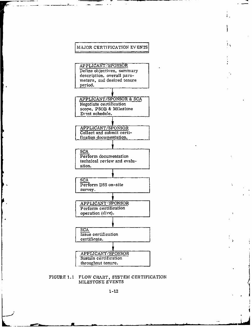
Figure 1-1 presents a flow chart of the System Certification Milestone Events. Theapplicant and SCA interplay and negotiations between milestones is stressed. Effectiveand frequent communication can avoid delays in planned schedules and reduce the overalleffort for the applicant and SCA.
I
I
1-I
E1--
- - - --.. ....- -- - 4
MAJOR CERTIFICATION EVENTS
APPLICANT./SPONSORDefine objectives, -summarydescription, overall para-meters, and desired tenureperiod.
APPLICANT/SPONSOR & SCANegotiate certificationscope, PSOB & MilestoneEvent schedule.
APPLICANT/SPONSORCollect and submit certi-fication documentation.
SCAPerform documentationtechnical review and evalu-ation.
SCAPerform DSS on-sitesurvey. J
APPLICANT 'SPONSORPerform certificationoperation (dive).
SCAIssue certificationcertificate.
APPLICANT/SPONSORSustain certificationthroughout tenure.
FIGURE 1.1 FLOW CFLkRT, SYSTEM CERTIFICATIONMILESTONE EVENTS
1-12
_.-I
CHAPTER II
SYSTEM CERTIFICATION SCOPE
2.1 INTRODUCTION
The system certification scope includes the pressure boundary, materials, equip-ment, sy.stems and operating procedures needed for safe operation and to recover from amalfunction or accident and above all, a system for sustaining life which will permit re-co'erv of the operators, divers, or occupants of the DSS without unduly imperiling theirhealth or well being.
This Chapter provides guidelines for defining those critical areas, componentsand systems of a DqS which must be considered for System Certification. Most accidentsresult from a series of events beginning with a single failure, often relatively minor, whichmay place the DSq Personnel or equipments under additional stresses. The avoidance orprevention of such initial failures in the normal operation of equipment enhances the over-all safety of the DSS.
The philosophy of certification is, therefore, only to consider recovery from asingle failure. Based on this philosophy systems and components may be determined tobe critical or non-critical.
2.2 SYSTEM CERTIFICATION SCOPE
The applicant shall submit to the SCA, for negotiation leading to ultimate approval,a detailed list of all portions of the DSS and its ancillary equipment which, in the applicant'sbest judgement, fall within the system certification scope as defined in 2. 3. Illustrativeexamples of such systems and characteristics are given in 2.4. In addition, the applicantshould include the criteria and supporting justification for limiting the specific scope sub-mitted. Those portions of the DSS that fall within the certification scope should meet allapplicable requirements discussed elsewhere in this Manual. Non-scope portions and sys-tems may be reviewed by the SCA for their contributions to the overall safety of design.Statements in this Manual pertaining to non-scope areas are for guidance only.
2.3 DEFINITION OF SYSTEM CERTIFICATION SCOPE
The System Certification qcope of a DSS is a list of those systems required toinsure and preserve the safety and well-being of its operators, divers, or occupants.It encompasses "life critical elements" of all systems, subsystems, components andportions of the DSS including normal operating and maintenance procedures which areneeded to insure the continuous physical well-being of the operators, divers, or-occupants.It also encompasses those emergency systems and procedures required to return themsafely from any depth. down to the maximum operating depth, back to the surface or toa subnmerged base under abnormal conditions following any non-catastrophic accident orcasualty which precludes continued normal operation of the DSS.
Components, systems, and portions of the DSS that require certification include:
a. All components, systems and portions of the DSS which, through malfunctionor failure could prevent the return of the DSS operators, divers, or occupants to the sur-face or to a submerged base.
2-1
,4-I}
b. All components, systems and portions of the DSS required to keep operators,divers, and"or passengers safelv on the surface following any ascent.
c. All con'poncnts, systems and portions of the DSS provided to rescue personnelfrom the DSql and r .turn them to the surface, support ship, a submerged base: or, in thecase of hyperbaric chambers, to ambient conditions outside the chamber.
d. All systems and components including temporary test equipments affecting trimand stahility conditions, both surfaced and submerged, which could prevent the safe recoveryof personnel from a DSS.
e. Normal and emergency operating procedures.
f. 'Maintenance procedures.
2.4 EXAMPLES OF AREAS OF A DSS INVOLVED IN SYSTEM CERTIFICATION
It is recognized that individual DSS designs will vary to the extent that no singlelist can adequately define the system certification scope for all cases. The followinglist of areas which could require certification is given for purposes of illustration andshould not be considered all inclusive or universally applicable.
a. The pressure hull, pressure vessels, hard structure and appurtenances.
b. The ballast systems which can be used for maintaining adequate freeboardwhen operating a submersible capsule or habitat on the surfacc or that can be used foremergency surfacing.
c. Jettisoning and emergency blow systems which can be used to return the DSSto the surface in the event of an emergency.
d. Normal and emergency life support systems which provide an acceptable at-mosphere to the DSS personnel.
e. Non-compensated equipment, subject to pressure, which may implode orexplode (see Appendices C and D).
f. Release devices for external appendages.
g. Fire fighting devices or systems.
h. Communication systems that enable personnel utilizing the DSS to communi-cate with support personnel.
i. Monitoring /detecting devices which will be depended upon to assure that theDSR does not exceed specified limits.
" Obstacle avoidance systems, such as active sonars, fathometers, passivesonars, TV viewing systems, optical viewing devices and periscopes.
k. In the case of a submersible, the propulsion system may be included whenthe submersible operates under or near overhangs, cliffs, canyons, etc.
2-2
-I
1. Accessibility to vital equipment which actuates recovery systems or is involvedin life support systems. These should include systems which may be required for recoveryof personnel from the DSS following a casualty.
m. Flotation or buoyancy systems whose failure or inadequacy could prevent thet return of the DSS personnel to the surface.
n. Electric power systems which include internal and external electrical protec-tive devices whose failure could result in malfunction of a critical component or system.
o. Written operating and maintenance procedures including pre- and post-dive pro-cedures for the particular DSS.
p. Support ship handling system components such as cranes, brakes, and cableswhen the DSS is handled with personnel aboard.
q. Components, systems, and portions of the DSS that protect the DSS personneldirectly or indirectly against the effects of accidents and hazards.
r. The diver-carried equipment, whis, acludes the systems, subsystems, com-ponents, and portions of the equipment located on the diver side of the umbilical or supplyhose connection required to insure and preserve the safety and well-being of the diver.such as:
(1) Diver's breathing gas systems, materials and their applications, valvesand regulators, breathing gas containers, carbon dioxide absorbers.
(2) Diver's headgear, face masks, mouthpieces, helmets.
(3) Diver's breathing gas hose, umbilicals, gas fittings, connectors, fasteners,and clothing.
(4) Diver's instrumentation, sensors, and alarms.
(5) Diver's electrical systems, communication systems, navigation systems,and heating systems.
s. Systems which provide control of the diver's body temperature and subsystemsand components that protect the diver against accidents and hazards in the underwaterenvironment.
t. Systems located on the gas supply side of the diver's umbilical or supply hose.
2.5 PRE-SURVEY OUTLINE BOOKLET (PSOB)
Upon approval of the negotiated certification scope by the SCA, a PSOB is to be pre-pared by the applicant. The PSOB is a detailed checklist that utilizes the certification scopeas the index and expands each scope item with typical requirements for recordable evidence,such as:
a. Design parameters
b. Design calculations and analyses
2-:3 ,).4
-- -*- -~L.
c. Material evaluations
d. Verification by model testing
e. Review of as-built drawings
f. Review of fabrication and inspection procedures
g. Material traceability
h. Review of NDT results
i. Proof tests
j. Surveillance program
k. Material survey
There are five PSOB guides presently available from the SCA. aid the applicant.These are:
(1) NAVSHIPS 0900-028-2020 "Pre-Survey Outline Booklet for MannedNon-Combatant Submersibles."
(2) NAVSHIPS 0994-009-701Q/NAVFACP-422.1, "Hyperbaric Facilities,Pre-Material Certification Checklist."
(3) NAVSHIPS 0994-013-7010, "Pre-Survey Outline Booklet for Diver Equipment."
(4) NAVSHIPS 0994-014-0010, "Pre-Survey Outline Booklet for StandardU.S. Navy Recompression Chamber Installations."
(5) NAVSHMPS 0994-014-9010, "Pre-Survey Outline Booklet for StandardU.S. Navy Surface Sup; -ted Diver Equipment Systems."
The line items of these PSOB guides are pre-printed in a format that follows atypical scope of certification and includes typical requirements for recordable evidence.The applicant should tailor his PSOB guides to his particular submersible, hyperbaricfacility, or diver equipment by checking the applicable items. Items which are not coveredby the PSOB but are judged to be applicable, due to their relationship to the system, shouldbe added on the additional sheets provided.
For other DSS, the applicant may wish to tailor the submersible PSOB for thesubmersible elements of the system (I.e., PTC, habitat) and tho hyperbaric facilitiesPSOB for the deck elements (i.e., decomprezsion/recompression chambers, handlingsystem).
After the PSOB is approved by the SCA, the applicant should use it as a checklistfor asseirbling the supporting recordable evidence. Documentation submitted by the ap-plicant should be Indexed to the PSOB item number to facilitate its technical review.
1
2-4
normal or casualty operations such as explosively jettisoning eternalequipr-.nt; (d) from collapse of any non-pressure-compensated elements.
(12) Fatigue load life of the pressure resisting components and piping for aspecified number of cycles in a cold seawater environment.
c. Drawings
The applicant should submit up-to-date copies of drawings of each componentand system evaluated in the design analysis. These drawings, showing all critical dimen-sions and tolerances relevant to performance, should be the actual drawings used for manu-facture and fabrication. Each component or item on a drawing should be identified by themanufacturer model or type number, vendor identification, applicable Military Specification,Federal Specification or Standard as appropriate.
3.3.4 Operability and Maintainability Criteria and Procedures
a. Operability Analyses
Tne applicant should submit the analyses used to evaluate the operability of theDSS. Such analyses normally include an information flow diagram, an operational sequencediagram, a human engineering analysis of the instrumentation and control layouts, and ananalysis of the life support monitoring and control systems. Included also should be an
analysis of the various ciergency modes-of operation to assure that the design reflects theneeds of these special conditions.
b. Maintainability Analyses
The applicant should submit the maintainability analysis used to develop themaintenance philosophy and general maintenance procedures. The analysis should show thatthe design permits rapid positive identification of malfunctions, and rapid isolation and repairof the faulty items by assigned DSS personnel.
c. Criteria and Procedures
The criteria and procedures upon which operation and maintenance are basedshould be explained. Human engineering factors and emergency procedures should beincluded.
d. Replacement Parts
Critical parts for replacement "in ind" should be readily available. Standardparts are preferred to those available only on special request. Replaceable equipment shouldbe designed so that incorrect installation is prevented.
e. Manuals
Operating and Maintenance Manuals are to be identified. The contents of thesemanuals, as they affect safe operation, will be considered in the certification process. (SeeChapter VII.)
3-5 q
Amwy6%

3.3 DESIGN REVIEW INFORMATION
Design review information should be submitted by the applicant for review. Theinformation should include at least the following:
a. System Certification Scope - 3. 3. 1
b. Summary Description of DSS - 3.3.2
c. Design Parameters - 3.3.2. a
d. Subsystem Descriptions - 3.3.3.b
e. Design .nalysis - 3.3.3
f. Operability and Maintainability Criteria and Procedures - 3.3.4
g. Material Justification - 3.3.5
h. Toxic and Flammable Materials - 3.3.6
i. Atmospheric Analysis - 3.3.7
3.3.1 Certification Scope
The Certification Scope, described in Chapter II, should be stated.
3.3.2 Summary Description of DSS
The applicant should submit a summary description of the DSS to facilitate the evalua-tion of the safety of the DSS. This summary should include a mission profile or dive scenario.There should be a written explanation of the features of the DSS with appropriate schematicdrawings to show the relationship of various systems and equipment used to accomplish opera-tional functions (see Paragraph 2.4.)
a. Design Parameters
The design parameters of the system must be identified. These design para-meters will provide the basis for evaluation of the adequacy of the design for system certifi-cation. General design parameters which are recommended for consideration by the appli-cant and which may be evaluated by the SCA include:
(1) Type of life support equipment
(2) Displacement /Volume/Manning Requirements
(3) Design safety factors
(4) Design life and service period
Effect of ambient operating conditions and mechanical shock/vibrations ondesign life
(6) Replacement or replenishment requirements
3-2
J_
(7) Depth/Pressure limitations
(8) Correlation with the mission profile (scenario) including supplyrequirements to support the maximum duration of mission
(9) Limits for breathing-gas composition, pressure and flow, temperature,
and humidity
(10) Specification and justification of breathing gas contamination limits
(11) Temperature limits for both normal and emergency operating conditions
(12) Thermal protection requirements
(13) Hazards
(14) Other physiological considerations
(15) Failure modes and effects concepts
(16) Emergency equipment requirements and capabilities
(17) Communications requirements
b. Subsystem Descriptions
Each subsystem within the certification scope should be described. Thesesubsystems should include the fluid systems, the electrical systems, compressed air andgas systems and significant mechanical and structural features. Each subsystem designshould, as a minimum, be submitted with both a written description and function/flowdiagram. The subsystem description should clearly delineate objectives of the design andsafety considerations. An analysis of the consequences of a failure or loss of normal modeshould be included. The diagram should show clearly how the subsystem accomplishes itsintended function. Sufficient information should be included to identify the specific compo-nents and their location, orientation, size, bill of material, etc.
Note: Failure mode analyses should be performed sufficiently early in thedesign process so that they may influence the detail design to developsuitable reliability, to insure safety of the personnel, and to indicaterequired redundancies.
3.3.3 Design Analysis
a. Design Calculations
Where design calculations are submitted to demonstrate the adequacy ofdesign, the calculations should clearly state all assumptions and rationale used in theanalysis. The calculations should indicate the effect of worst case drawing dimensions andtolerances or "as-built" dimensions. Potential corrosion should also be considered.Appropriate reference should be made either to applicable test data or to operating experi-ence when they are used to support a calculation technique. The design calculations shouldc ..rl. wh, in an orderly m oner; the adequacy of the item analyzed in terms of thedo.cig n parameters of the DSS. Info-mation should be submitted in sufficient detail topnrmit independent analysis of the ccsign. Documentation submitted by the applicant
3 -3a
should be tabulated to assure that the information completely covers the design. Thedocuments should be also indexed to the PSOB to facilitate the technical review.
b. Stress Analyses
The applicant should demonstrate that the design is satisfactory by means ofdetailed stress analyses and the appropriate tests as described herein. Test programsperformed by the applicant in support of system certification should cover the effects of allstress analyses considerations.
Stress analyses and test reports submitted by the applicant should also considerthe worst loading case which includes the cumulative detrimental effects of design2 allowances,dimensional variations and tolerances.
Examples of loads to be considered are:
(1) Weight of water used for hydrostatic testing.
(2) Forces encountered while transporting, securing, removing, orhandling the DSS or components thereof.
(3) Static loads imposed by the clamping or securing means used to securethe DSS.
(4) 'Normal operating pressure of gas within the DSS.
(5) Thermal stresses due to the normal operating temperatures of the DSS.
(6) Reactions due to differential thermal expansion of the DSS and the struc-ture to which it may be fixed, or due to elastic expansion of the DSScaused by internal pressure.
(7) Vibration transmitted from a ship or aircraft which may be transporting
the components of the DSS.
(8) Shock, including accidental blows.
(9) In the case of portable chambers,
(a) Forces developed while hoisting, transshipping or transporting thechamber while pressurized to a specific pressure. Accidentaldropping through a specified reasonable distance (such as 3 or 4 in.)while pressurized to a specified pressure.
(b) Reactions due to clamping or securing to an irregular base. Mini-mum qualifications for a base may be specified as a design para-meter and, if so, shoat"d be cited in the Operating Manual as a sys-tem limitation or precaution.
(10) Forces developed by shipboard accelerations imposed by ship motions.
,Il,' Incfld. lnsa r.h . s those encountered when: (a) launching, retrieving, orhandling certain DSS; (b) bottoming a DSS at normal rate of descent; (c) in
3-4
I
, normal or casualty operations such as explosively jettisoning external I
equiprr.-nt; (d) from collapse of any non-pressure-compensated elements.
(12) Fatigue load life of the pressure resisting components and piping for aspecified number of cycles in a cold seawater environment.
C. Draw~ings
The applicant should submit up-to-date copies of drawings of each componentand system evaluated in the design analysis. These drawings, showing all critical dimen-sions and tolerances relevant to performance, should be the actual drawings used for manu-facture and fabrication. Each component or item on a drawing should be identified by themanufacturer model or type number, vendor identification, applicable Military Specification,Federal Specification or Standard as appropriate.
3.3.4 Operability and Maintainability Criteria and Procedures
a. Operability Analyses
Tne applicant should submit the analyses used to evaluate the operability of theDSS. Such analyses normally include an information flow diagram, an operational sequencediagram, a human engineering analysis of the instrumentation and control layouts, and ananalysis of the life support monitoring and control systems. Included also should be an
the various emergency modes of operation to assure that the design reflects theneeds of these special conditions.
b. IMaintainability Analyses
The applicant should submit the maintainability analysis used to develop themaintenance philosophy and general maintenance procedures. The analysis should show thatthe design permits rapid positive identification of malfunctions, and rapid isolation and repairof the faulty items by assigned DSS personnel.
c. Criteria and Procedures"1
The criteria and procedures upon which operation and maintenance are basedshould be explained. Human engineering factors and emergency procedures should beincluded.
d. Replacement Parts
Critical parts for replacement "in kind" should be readily available. Standardparts are preferred to those available only on special request. Replaceable equipment shouldbe designed so that incorrect installation is prevented.
e. Manuals
Operating and Maintenance Manuals are to be identified. The contents of thesemanuals, as they affect safe operation, will be considered in the certification process. (SeeChapter VII.)
3-5 4
:3.:3.5 \Iaterial Justification
The applicant should justify the materials and their applications as used in the designof the DSS for the expected service environments. All of the materials considered to bewithin the ce-tification scope should be identified. The relative location of the materialssh.udd he included and verification of their compatibility with adjacent materials should beprox Adccd where electrolytic corrosion or other material incompatibility problems are aconcern.
It is onticipated that some DSS will be designed to operate at greater depths andth u , rtm iatcrials, new applications for time tested materials, and new configurations
iy be employed. It is not the intent of this manual to limit the materials and theirapplic:tioni. The intent is to permit the use of new materials or materials in newapplications whenever sufficient data exists to show that the material adequacy of theDSS, and hence the safety of the personnel utilizing the DSS, is reasonably assured. Theless the amount of available information and experience with a material or application,the greater the burden upon the applicant to justify the adequacy of the proposed materialor application. For the purpose of System Certification the possible materials and/orcomponents are grouped into the following three categories:
a. Category 1.
Materials and components with which there is both considerable fabricationexperience and also considerable operating experience in the intended environment andapplication.
b. Category 2.
Materials and components which have not been used extensively in similarapplications but are classed as conventional due to identification by Military Specifications,Federal Specifications, or recognized American Commercial Standards such as those pub-lished by the American Society of Mechanical Engineers or the American Society for Testingand Materials. Materials or components available as standard stock items built to a recog-nized commercial or Federal standard will be considered in this category. Examples ofmaterials and components that are presently considered to be in this category are certaintypes of aluminum, titanium, and some high and low strength steels. The determination ofacceptable properties and allowable operating stresh values will be based on the recommenda-tions and supporting information provided by the applicant.
c. Category 3.
Materials and components for whicb definitive information and experience arenot a'. ailable. The basis for testing and the criteria for acceptance of new materials andcomponents will not automatically be the same as for those currently in use. The proof ofacceptability of the material or component and justification of the acceptance criteria mustbe provided by the applicant. THIS MANUAL NEITHER SPECIFIES ACCEPTANCE TESTSFOR NEW COMPONENTS OR MATERIALS NOR ARBITRARILY DEFINES ALLOWABLEOPERATTNG PARAMETERS. For example, the applicant should demonstrate the effect ofdefects, manufacturing tolerances and production variations upon the reliability of thematerial or component by appropriate model ad/Ui p",rototyett, i a simulat..environment. The applicant must establish that the new material or component possessesat least the same factor of safety as is provided by proven materials in a similar application.
3-6
-~4

As .. minimum the applicant should submit the informat 'on required in Appendix A for thejustification of Category 3 items.
3.3.6 Toxic and Flammable Materials
The applicant should submit a list of all potentially toxic and/or flammable materialsused in construction and fabrication and installed in the DSS. Toxic materials may be paints,insulation, adhesives, sealants, lubricants, equipment, instruments, fittings or other itemsthat could give off noxious fumes at their operating pressure/temperature or at any tempera-ture below 200 0 F. Flammable materials include materials in a form which will ig-nite orexplode from an electric spark or from heating and which, if so ignited, will independentlysupport combustion in the presence of air or in any oxygen enriched atmosphere that may beencountered in the DSS under either normal or emergency conditions.
3.3.7 Atmospheric Analysis
Prior to manned use of the DSS an analysis of the DSS atmosphere must be submittedfor review. (See Appendix F).
3 -7/(3 -b blanik)
II
- --- __
CHAPTER IV
CONSTRUCTION, FABRICATION AND ASSEMBLY
4.1 iNTFRODUCTION
This chapter describes the documentation the applicant should submit to the SCAconcerning construction, fabrication, and assembly processes that affect performance ofthe DSS. This documentation should include supplementary information such as work pro-cedures, heat treating instructions, welding procedures, in-process inspection procedures,assembly procedures and clean room procedures that are needed to accomplish the con-struction and also whether or not such process information is specifically identified orreferenced in the design drawings.
4.2 RECORDABLE EVIDENCE
The information submitted by the applicant relative to construction, fabricationand assembly processes should include the following:
a. Identification of the construction, fabrication and assembly process thataffect design performance.
Y b. Inclusion of the process documents.
c. Substantiation of the adequacy of these processes based on previous usehistory or based on process qualifications and tests.
4.3 CONSTRUCTION AND FABRICATION PROCESS REQUIREMENTS
In addition to the process evaluation required in 4.2 above, the applicant shouldalso comply with the following requirements.
4.3. 1 Welded Construction
All welding should be done in accordance with written welding procedures whichhave been qualified. The welding procedures, procedure qualification requirements andwelder qualifications should be utilized as controls over welding processes. The appli-cant is required to identify and/or submit the welding procedures used and make availablefor review, the procedure and the welder qualification records, as well as the results ofthe weld non-destructive tests. In addition, proof of fracture resistance of the weldmentshould be demonstrated by a test that is appropriate for the material selected. For ex-ample, a drop weight test or a drop weight tear test may be substituted for the explosionbulge test, where required. Repair involving heat or welding should be accomplished inaccordance with specific requirements and subjected to, as a minimum, the tests and in-spections specified for construction. Both personnel and procedures for repair must "be qualified also.
4. 3. 2 Brazed Construction
All brazing should be done in accordance with written brazing procedures that havebeen qualified, and by brazers who ha- .. -,qualified to perform the required brazingoperations. The applicant is required to identify and/or submit the brazing procedures
4-1
used and make available for review the procedures and the brazer qualification records, as
well as the results of the brazed joint non-destructive test.4.3.3 Qualifications
The following welding and brazing procedures are typical of good qualificationpractices:
MIL-STD-0024.3 (Ships), "Welding and Brazing Procedures and PerformanceQualification"
NAYSHIPS 0900-001-7000, "Fabrication and Inspection of Brazed Piping Systems"ASME Boiler and Pressure Vessel Code, Section IX, "Welding Qualification"
-1. 3.4 Cleaning
It is recommended that the cleaning of breathing gas systems during assembly orfabrication be in accordance with an overall contamination control plan. System cleaningmay be accomplished during assembly/fabrication, upon final completion of assembly, ora combination of both, at the option of the sponsor. The final levels of contamination mustmeet the requirements specified and justified by the sponsor and as accepted by the SCA.Refer to the Appendices F and G for guidance in cleaning and atmospheric evaluation.
/
4!
4-2
i

CHAPTER V
QUALITY ASSURANCE
5. 1 INTRODUCTION
The applicant should assure that quality assurance provisions are maintained whichdemonstrate that the DSS has been constructed in accordance with specified requirements.These quality assurance provisions should result in recorded evidence related to:
a. Design and Drawing Control
b. .latcrial Control
C. Fabrication, Manufacturing and Dimensional Control
d. Testing and Inspection Control
Applying quality assurance provisions to all parts of the system in which failurecan result in a hazard to DSS personnel will insure that the performance parameters ofthe system are achieved at the highest practical level of safety.
It is recognized that quality assurance provisions are more easily applied duringconstruction of a DSS, however, it is none the less the responsibility of the applicant toestablish means by which the quality of existing DSS may be evaluated.
5.2 QUALITY ASSURANCE PROVISIONS
Due to the life support nature of DSS, Quality Assurance and personnel safety areinseparable. All Quality Assurance considerations are in areas that also affect the safetyof the operators, divers or occupants. These areas include, for example, initial forming,fabrication, assembly, cleaning, testing, inspection and preparation for delivery. Theauthority and responsibility of quality assurance personnel in each of these areas shouldbe clearly delineated. (The aspects of Quality Assurance that the applicant should considerand justify in his request for system certificaticn of the LSS are illustrated by, but not lim-ited to, those mentioned.) Manufacturing, fabrication, and azqembly work conducted within theDSS builder',- plant should be carefully controlled. Such control should include a formal review
7 / and engineering evaluation of all manufacturing tolerances ,and deviai~ons. An equally ef-fective control over purchase materials and sub-contracted work should be provided.
An applicant for "Continuance of System Certification", or "Recertifica'lon" shoulddemonstrate that an effective Quality Assurance Program will be (or has beer) applied where
repair, (other than simple installati3n of "in-kind" rplaceable elements), alterations and/oroverhaul are involved.
The applicant should maintain records and other data essential to the economic andeffective operation of his quality control program. These records should be available forreview! ! the System Certification Authority and copies of individual records may be re-cuired to be furnished on request. Records are one of the forms of objective evidence ofproper qualit control. The quality control pro1ram should be planned so as to insure thatthe!.. are complete and reliable.
5-1
tI
5.3 DRAWING CONTROL
Th-, applicant should assure that current design drawings are promptly distributedto manufacturing personnel and that only current drawings are used. The applicant ihouldshow that his drawxing control system requires approval of design changes, including mate-riad substitutions, before such changes are incorporated into the finished product. Ileshould also show that his drawing control system requires removal of obsolete drawingsand change requirements from all points of issue and use. The control system shouldalso provide control over supplemental specifications, process ins+-actions, productionengineering instructions, industrial engineering instructions and work instructionsthat either implement the design or supplement design drawings to accomplish themanufacture and assembly of the DSS. The applicant should maintain the technicaldata and drawings required by the on-site survey team to determine whether or not thesystem ccrtification scope items for the DSS correlate to the design.
5.4 MATERIAL CONTROL
For new DSS construction, the applicant should show that the program for materialcontrol is effective. The program should assure that materials used conform to the appli-cable physical, chemical or other technical requirements. A means of keeping track ofthe identity of tested and approved materials should be implemented. Controls should beestablished to prevent the inadvertent use of other than as specified material.
5.5 FABRICATION, MANUFACTURING AND DIMENSIONAL CONTROL
The applicant should show that the quality program assures that the DSS has beenmanufactured in accordance with the approved drawings and manufacturing processes. Theapplicant should also substantiate that required dimensional tolerances (such as thickness,mismatch, out-of-plane, out-of-round, sphericity, etc.) were achieved.
5.6 TESTING AND INSPECTION CONTROL
The applicant should show that there is an effective inspection system in effectthat establishes the inspections and tests necessary to substantiate that the certificationscope items of the DSS are in conformance with the requirements. The inspection systemshould incorporate clear, complete and current instructions for inspection and testing andshould include criteria for approval and rejection. Records of all inspections and testsshould be maintained that indicate the nature and number of observations made, the num-ber and type of deficiencies found, the quantities approved and rejected and the nature ofthe corrective action taken.
The inspection system should verify that the latest applicable drawings, specifica-tions and process controls, with all authorized changes incorporated, are used for fabri-cation, inspection and testing. The inspection system should describe the training andqualifica'iun of inspectors and should include demonstration of competence in techniquessuch as radiographic inspections and ultrasonic inspection. The inspection system shouldalso provide for calibration of inspection equipment.
5. 7 WORKMANSHIP
The hazards associated with the purformance requtremcnts of a DSS dictate theuse of only high quality workmanship. Conscquently, the evaluation of the workmanshipevident in the finished DSS is a significant factor in determining the acceptability of the
5-2

iudi; (Ital DSS. Acceptance standards to establish high quality workmanship are difficultto .,pecify. It is the responsibility of the prudent designer and builder to oversee the work-man-hip of the DSS to assure high quality.
3. 8 QUALITY ASSURANCE INFORMATION
The applicant should submit information relative to the quality assurance provisionsin stfficient dp:h and detail to permit audit and evaluation by the SCA. All quality control,insptvction and material identification records should be retained, at a Ikown location,thrc..,hout the zystem certification period. The system certification period will not beexten'led without the availability of such records.
t
V5
1.
,1.
-i- l
CHAPTER VI
TESTING
6.1 INTRODUCTION
The applicant should develop and implement a test program which will demonstratethe adequacy of all systems and equipment within the certification scope. Pressure vesselstrength, flotation and buoyancy systems, piping systems, emergency deballasting andjettisoning systems, life suport systems (including breathing gas purity control), electricalinsulation integrity and safety features are examples of items to be tested.
The test program for the DSS should be documented in the form of a series of testprocedures. The applicant should provide both procedures -Ind test data in order to obtainsystem certification. In general, tests required for syste. certification should be groupedin three categories:
a. Development Tests
This group covers those tests required to verify the design basis of the DSS.The performance of materials, mechanical designs and configurations, and systems whichare unique or untried in a similar environment and are within the scope of certification mustbe demonstrated by such tests.
The tests to demonstrate the design basis of the DSS need not necessarily beperformed on the actual DSS. In some instances, testing of a duplicate component may beappropriate., A further description of developmental material and structural testing require-ments can be found in Appendix B.
b. Quality Assurance Tests
These tests are performed to demonstrate that the components, materials andfabrication of the DSS do, in fact, conform to design. They include such items as radio-graphic tests of welds, fabrication tolerance measurement, calibration tests, breathing gaspurity tests, vendor's acceptance tests, etc.
c, Operational Tests/
These tests are intended to confirm the capability of design, the operationalcharacteristics and the operational procedures to be used with the DSS. For purposes ofconvenience, proof tests are handled as part of this category.
It is the purpose of the remainder of this chapter to describe the requirements for
operational and proof testing.
6.2 GENERAL REQUIREMENTS FOR OPERATIONAL AND PROOF TESTS
The applicant should submit copies of all proof, pre-builder's or pre-sea trial testprocedures and operational test procedures that are within the scope of certification to theSCA for information prior to conducting the tests.
The format of the test procedures should be such that both a test procedure and thedata to be collected from that test will be contained in a single document.
6-1
As each step in a procedure which requires that a component or system operate in aprescribed maimer) is satisfactorily completed, this fact should be witnessed by the signature(or imtials) of a representative of t',. builder's test or quality assurance organization. Thedate on which t,, str p was perform2d should also be indicated. If the step requires that aparticular parameter be within a specified range, both the required range and the actualvalue should be recorded.
Operational test procedures must be approved by the DSS designer.
Operational test procedures of the system for characteristics which are iden.ified inthe system certification scope must be reviewed by the SCA. A test schedule should beprovided to allow witnessing those tests deemed critical by the SCA.
The SCA reserves the right to require a rerun of any or all of the operational tests ifresults are not clear or conclusive.
Upon completion of all operational testing, the SCA should be supplied with an indexeddocument ccntaining copies of all completed operational test procedures indicating the results.
6.3 PROOF, PRE-BUILDER OR PRE-SEA TRIAL TESTS
Hydrostatic and/or pneumatic tests shall be perfomed on all components of the DSSwithin the system certification scope that are subjected to fluid pressure during operation.Pressure vessels, hard structure, penetration fittings, and piping should be tested in accor-dance with the parameters of Appendix B. A log of all joints should be maintained during thehydrostatic and/or pneumatic test and their satisfactory tightness should be indicated byinspector's initials and date. This log should be a part of the completed procedure.
A flush must be performed on all systems in which valve tightness or a motion ofclose fitting parts is required for the safe operation of the DSS. Such systems may include(but are not limited to) freeboard ballast system, trim and drain system, and hydraulic, gas,water, or air systems. Satisfactory completion of the flush will be achieved upon test verifi-cation of the degree of cleanliness as specified and justified by the designer.
Hydrocarbon oils, such as kerosene, shall not be used for hydrostatic testing ofbreathing gas systems. Corrosion inhibitors or other materials added to water used forhydrostatic testing shall be reported to the System Certification Authority by the applicant,and shall not leave toxic, noxious, flammable, or corrosion-inducing residues.
A cleaning procedure must be performed on all respiratory related life support andbreathing gas systems. Such systems may include (but are not limited to) divers' breathingapparatus, hyperbaric chamber interiors, oxygen and diluent gas piping.
Satisfactory completion of the cleaning procedure will be achieved upon test verifica-tion of cleanliness and trace contaminant levels as specified and justified by the designer.See.Appendices F and G.
The operation of any fire-extinguishing systems should be verified throughout the firesusceptible pressure range of the DSS. To reduce damage to delicate equipment, the demon-stration of the fire extinguishing system prior to complete outfitting may be desirable.
The applicant should prepare and submit test procedures designed to demonstrate theadequacy of electrical insulation of any electrical circuits. These procedures should specify
6 -2
I
not only the pass/fail criteria for the test, but also such test conditions as water tempera-ture, pressure and length of exposure time.
All electrical cable, equipment and devices should be subjected to a dielectricstrength test at 60 Hertz voltage for one minute. Military specifications specify dielectrictest voltages. For other procurement specifications a test voltage of twice rated plus 1000volts should be performed. The cable dielectric tests should be performed between allconductors and the sheath and also between conductors. This is a "go," "no-go" criteriatest. Because of the destructive nature of a. c. dielectric testing this type testing should belimited to the manufacturer plant tests as part of procurement procedures or after a majoroverhaul of an equipment or device (e.g., a rewound motor). All subsequent insulationresistance testing should be with a d.c. potential. The d.c. voltage should not be less than500 volts for electrical cables, equipment or devices. Insulation resistance measurementsof all safety circuits excluding the actuating device should be made part of the pre-dive check-off list. A proposed log of the measurement readings should be submitted by the applicant.A log of.periodic insulation resistance readings for all electrical systems and circuits is avaluable tool in planning maintenance and repair schedules. Humidity, contamination ofinsulation materials, accumulation of foreign matter on insulating surfaces and thelength of cables have a bearing on insulation resistance values. Therefore, the change ininsulation resistance values is of major significance. After being idle for a period, equip-ment and cables may exhibit lower than normal readings. However, after a time in operationthe resistance may return to normal. This is an indication of moisture caused by highhumidity. On the other hand, a steady gradual decline in insulation resistance is an indica-tion of insulation contamination or collection of foreign matter on the insulating surfaces.One megohm is considered an acceptable value for all installed electrical systems. Anysizable drop from this value should be considered as a warning of impending failure. Forpersonnel protection and safety 50, 000 ohms is the lowest acceptable insulation resistancelimit.
Static stability of the DSS must be demonstrated for all normal trim conditions.(This does not apply to fixed shore or shipboard hyperbaric facilities.)
Operating and casualty procedures for systems affecting personnel safety shall beperformed. This should include a demonstration of the accessibility to vital safety equip-ment or systems to insure personnel can operate the equipment and systems under emer-gency conditions. Where an actual demonstration is not practical the applicant may proposealternate means of demonstrating the acceptability of the procedures. The satisfactoryaccomplishment of each step in each procedure should be initialed and dated by the respon-sible person in charge.
Tests should be performed with different gas supply pressures ranging from maximumto minimum to demonstrate that the design conditions of pressure regulation are attained.Pressure measurements should be made at each design level of pressure. Gas flow measure-ments should be made to demonstrate flow adequacy.
Maximum design gas pressure shoUl '.e introduced into each part of the assembledDSS equipment and appropriate testing proceAures should be used to demonstrate that theequipment is satisfactorily resistant to external leakage. Leakage acceptance criteriashould be submitted to the System Certification Authority prior to the conduction of the tests.
Tests should be performed with different gas supply pressures ranging from maximumto minimum to uitrndrie the degree of intc.rna.L le..age, if any, of gras-pressure and flowcontrol devices. Leakage acceptance critc.ria should be submitted to the System CertificationAuthority prior to the conduction of the tests.
6-3
Appropriate pre-operational test procedures should be submitted to the System Certi-fication Authority for demonstrating the design performance of selected function of the DSSequipment. The tests should be grouped in two categories: equipment functions and opera-tor /diver functions.
a. I st procedures should be formulated by the applicant to demonstrate theadequacy of the functions of selected equipment, subsystems and components. A typicalsu'bsystcm could be the emergency gas system. A typical component could be a by-passvalve. These tests should be conducted with the fully assembled equipment unless specialtest fixtures are required.
b. Test procedures should be formulated by the applicant to demonstrate theacceptability of the functions required by the operator/diver to operate the DSS equipment.Typical operator/diver functions could consist of operation of the different valves and regula-tors under typical conditions, such as limited visibility. These tests should be conductedwith the fully assembled equipment in place.
6.4 BUILDER'S OR SEA-TRIALS
All operating and casualty procedures not demonstrated in pre-builder trial testingshall be performed prior to final certification. Each step of each procedure should beinitialed and dated when satisfactorily accomplished.
In the case of DSS that are being built for, overhauled, or otherwise acquired by theU.S. Navy, the following documents should be prepared and forwarded to the SCA by thesponsor/applicant to allow the trials to proceed prior to achieving system certification:
a. A statement that all deficiencies pointed out by the SCA on-site survey havebeen corrected and the DSS is satisfactory for the initiation of sea trials.
b. A statement detailing the trial schedule including a brief of the proposed trialagenda.
c. A statement of the anticipated area of operation reported by latitude and longi-tude, as applicable.
d. A description of general environmental considerations that have been givenconcerning safety (e.g., sea state limits, visibility limits, DSS handling capabilities, limitson diving under overhangs, cables, caves, etc.).
e. A statement of provisions for contractor and/or Navy surface support units.
f. A description of communication arrangements between the DSS and supportunits and between support units and shore.
g. A statement of rescue alternatives available.
A submersible DSS must be subjected to a test dive to the maximum depth at whichit is to be certified to operate. Whenever possible, an unmanned dive prior to the manneddive should be accomplished. In achieving this maximum depth, the DSS must be maintainedat a depth of approximately 100 feet before proceeding to deeper submergences. If the DSSis not designed to be maintained at a depth of 100 feet theh an alternte m .eth.d of chevinshallow depth inspection should be proposed. All joints and penetrations accessible fromwithin the DSS should be inspected visually at this depth. All components, such as valves,
6-4

whose operation is subjected to submergence pressure and whose operation is required forsafe operation of the DSS, should be operationally tested; welds, other joints and valvesshould be inspected; and the inspection results should be logged. The submergence shouldthen be increased in increments of approximately 20% of the maximum operating depthuntil the nmixinimn operating depth is reached. At each 20% increment, the DSS shouldachieve neutral buoyancy while the closures are reinspected and valves recycled. Unsatis-factory operation of a valve or unsatisfactory :eak rate shall be cause for failure of the test.The test dive may be a single dive, as described, or a series of dives to accomplish the samepurpose. A log of carbon dioxide, oxygen, temperature and pressure shall also bemaintained. Readings should be taken at 30 minutes intervals or less.
A non-submersible DSS should also be subjected to an initial incremental pressuriza-tion with stops at appropriate pressures to cycle equipment and check for leakage.
The capability of all DSS power supplies in the system certification scope must bedemonstrated to operate satisfactorily until they have met the designer's specifiedendurance.
*, The capability of the normal and emergency life support systems must be demon-strated to operate satisfactorily until they have met the designer's specified endurance.
The operation of the emergency deballasting or jettisoning systems should be deomostrated at-sea, where practicable. Where such operation may partially destroy the DSS, asimulated emergency deballasting or jettisoning test may be performed. Such a test simula-tion must be submitted for review to the SCA for approval of the concept prior to itsaccomplishment.
A means of releasing external appendages (e. g., boom mounted light and cameraarrays, anchors, sample baskets, manipulators, etc.) should also be provided. The func-tion of these devices should be to release in the event they become entangled or embeddedso as to endanger the DSS. Testing the systems for satisfactory operations should be per-formed under adverse trim conditions, and where practicable should be perfoimed at an"at-sea-demonstration."
All deficiencies noted during the test dive/pressurizations shall be corrected asdirected by the SCA. Additional deep dives/pressurizations may be required as necessary.
Adequate instrumentation should be provided, where applicable, to measure thedeformation and strain in the pressure vessel and where feasible in the section of theexostructure which supports vital devices in order that comparable data may be obtainedin the process of the test dive to verify design calculations.
6.5 OPERATIONAL TESTS OF DIVER EQUIPMENT
a. The applicant should prepare and submit test procedures designed to demon-strate the operational characteristics of the diver equipment. These tests shouldbe formulated to assist a diver in systematically demonstrating the operationalcharacteristics of the diver equipment.
b. The operational tests should be performed by a diver acceptable tothe System Certification Authority. The diver should prepare a written reporton the operational characteristics of the diver equipment. This report should be a
6-5

p:rt of the tndexed document containing completed copies of all test procedures.
c. Upon -completion of the operational tests a careful inspection should bemade of the diver equipment, subsystems and components. This inspection isintended to verify that no condition has developed, as a result of the tests, whichcould be dangerous or which could impair the satisfactory operation of the divereq uipment.
6-I
6-6
~~1
CHAPTER VII
OPERABILITY AND MAINTAINABILITY
7. 1 INTRODUCTION
This chapter specifies the minimum requirements which the applicant should meetto assure the operability and maintainability of the DSS. Part of these requirements arec:)vered in Paragraph 3.3.4, Operability and Maintainability Criteria and Procedures. Inaddition to the analyses, written procedures must be provided to cover normal and emergencyoprations, repairs and maintenance, and periodic inspections.
7.2 REQUIREMENTSf
Written procedures are required for the following purposes:
a. To insure that the normal operation of the DSS is within the safe operatingconditions for which certification is requested.
b. To insure that there are adequate corrective measures to cope with emer-gencies.
c. To insure that there are check lists of prerequisites for various major evolu-.tions (e.g., pre-dive and post-dive procedures, repairs and maintenance, and periodicinspections)..
d. To insure that information available for training of operators is consistentwith safe operation of the DSS.
7 * 3 DEMONSTRATIONS
The adequacy of the normal and emergency procedures formulated by the applicantfor operation of the DSS should be demonstrated to the SCA (see Chapter VI). Satisfactoryaccomplishment of each step in each procedure should be verified by initialing and datingby the SCA's representative. In cases where it is found that a procedure cannot be performedin a satisfactory manner, the applicant must prepare an alternate procedure for accomplish-ing the desired objective.
7.4 OPERATING MANUAL
a. An operating manual or manuals should be provided describing all phases ofDSS operation. As a minimum the following sections should be included:
(1) System Description
This section should identify and describe the purpose and functionaloperation of all systems.
7-1
a - L
(2) Component Description
Sufficient design information should be included to identify and describeall major system components.
(3) Instrumentation and Controls
This section should discuss the control philosophy used in the system de-sign and provide a detailed description of the controls and instrumenta-tion used.
(4) Normal Operation
This section should identify all normal system operations and normalevolutions which involve personnel. Detailed, step-by-step, operating
procedures for these normal operations and evolutions should be pro-vided.
(5) Emergency Operation /
This section should identify all conditions of emergency operation andprovide procedures to be followed in the event of their occurrence.Emergency operation is defined as operation under conditions of systemmalfunction such as loss of power, component failure, physical damage,fire and in the case of diver equipment, loss of breathing gas pressureor flooding of breathing circuits.
(6) System Limitations, Precautions and Setpoints
In this section the applicant should clearly identify all DSS operationallimitations. This section should also state all precautions to be takenduring normal operation to preclude potentially unsafe conditions.A list of system operation setpoints which represent the normal oper-ation of the system should be included. See Appendix E for Life Sup-port System Limits.
(7) Operations Check Lists
The applicant should provide an operations check list which will be usedto verify proper system alignment under all normal operating conditions.Check lists should identify the support equipment required to major oper-ational evolutions, such as pre-dive preparations, diving, post-dive ser-vicing, etc. A condition of certification of the DSS will be that the supportequipment is operable and performing properly.
(8) Handling Operations
The applicant should provide handling procedures to cover any intendedhandling of the DSS such as during the air/sea interface penetration andmating. The procedures should, where appropriate, include details andprecautions for handling, lifting, securing, break-down and reassemblyof the DS- fortransporti .
7-2

b. The operating procedures (normal and emergency) will be verified in the testprog i am of the DSS to demonstrate that the procedures are satisfactory (see Chapter VI).Compliance with these procedures will be part of the system certification conditions. Anychanges to the procedures must be submitted to the SCA for review.
7.5 MAINTENANCE MANUAL
a. "Sustaining System Certification" is predicaed on maintenance of the DSS inthe "as certified" condition. Accordingly, the applicant/sponsor should prepare amaintenance manual which should include, as a minimum, the following subsections:
(1) Preventive maintenance including calibration and alignment of instru-
mentation and other equipment, as appropriate, in the DSS.
(2) Corrective maintenance including repair and replacement of components.
(3) System reentry procedures including post repair inspections and re-testing required to insure proper integrity and cleanliness of systemsand equipment.
b. The applicant should provide instructions for conducting periodic inspectionand tests to insure continued safe operation of the DSS. The instructions should include thescope of the inspection, tests and pass/fail criteria. These periodic inspections and testswill be a condition for "Sustaining Systems Certification." Specific periods for DSS over-haul should also be stated.
7-3/(7-4 blank)
CHAPTER VIII
ON-SITE SURVEY OF DSS
S. 1 INTRODUCTION
Upon completion of all testing, an on-site survey of the "as built" DSS will bemade by the SCA. The purpose of the on-site survey is to determine, within the establishedcertification scope, that the system, "as built," is in accordance with the technical packagethat was submitted for review.
S.2 SURVEY TEAM PERSONNEL
A survey team comprised of personnel representing at least the SCA and the spon-sor /applicant will conduct the survey. The applicant should provide additional personnelas required to assist the survey team. Acceptability of survey personnel qualificationswill be determined by the SCA.
S . 8.3 SURVEY PROCEDURES
8. 3. 1 Survey Outline
The PSOB which has been used as a check-off list during the documentation tech-nical review is further utilized as the survey outline. Line items of the PSOB which havenot been satisfied earlier may be completed during the on-site survey.
8. 3. 2 Recordable Evidence
One of the main facets of the survey is the recordable evidence to support that theDSS is actually built as designed and that it will perform to the limits for which certifica-tion is being requested. Accordingly, the survey team will review recordable evidence insufficient detail and depth to support a conclusion as to the acceptability of the DSS. Theapplicant should assure, prior to a survey, that necessary recordable evidence not pre-viously submitted to the SCA is readily available for the survey team.
t 8.3.3 Extent
The survey in general will include a review of:
a. The actual "as built" drawings used to construct the DSS.
( b. The drawing control procedures and records.
c. The quality assurance system, quality control documentation proceduresand records.
d. The construction, manufacturing and assembly procedures and records.
e. The construction, fabrication and assembly test procedures and records.
f. The system proof and ,erformance test procedures and records.
g. The system cleaning procedures and records.
8-1
(
h. The accessibility of vital equipment and components.
i. The quality of workmanship in the DSS.
8.3.4 Evaluation
upon completion of the survey, the SCA will forward the results of the survey team'sevaluation of the DSS to the applicant for action. All deficiencies noted as "IA- must beaccomplished prior to manned use" during the survey shall be corrected prior to furthermanned trials of the DSS. All deficiencies noted as "IB- must be accomplished prior tosystem certification" shall be corrected prior to issuance of the system certification. Alldeficiencies noted as "Il-desirable" may be corrected at the sponsor's option.
8-
I,
)
- I
, 8-2
CHAPTER IXSYSTEM CERTIFICATION APPLICATION
9.1 INTRODUCTION
The purpose of this chapter is to assist the applicant in the preparation of an applica-tion for certification in accordance with the requirements of this Manual.
9.2 APPLICATION
The Naval activity desiring to utilize a fixed shore-based facility should apply to theNAVFAC SCA (NAVFAC 04B); all others should apply to the NAVSHIPS SCA (SHIPS OOC).An information copy should be sent to CNM (MAT 034). The application should state thefollowing:
* General description of the DSS.
* Overall system parameters.
* Desired mission profile or dive scenario.
. * Desired certification objectives defining the operational limits for whichcertification is being requested (i.e. pressure, temperature, time, sea-state, etc.).
* Desired tenure of certification.
The applicant should then identify tho. critical systems of the DSS and establish thefollowing preliminary documents:
* Scope of System Certification
* Pre-Survey Outline Booklet
* Certification Milestonie Event Schedule
These should then be negotiated with and approved by the SCA. On the basis of theapproved version of these documents, the cost of the certification technical review andother related cost, such as travel expenses for the survey team, will be estimated bythe SCA.
Utilizinm the approved scope and PSOB as guides, the applicant should prepare andsubmi, the following documentation in a timely manner to meet the milestone event schedule:
• Design Review Information - See Chapter III.
, Construction, Fabrication and Assembly Information - See Chapter IV.
* Quality Program Information - See Chapter V.
* Test Program Information - See Chapter Vi.
* Operating and Maintenance Procedures - See Chapter VII.
~9-1
t*
This information should not be considered to be all inclusive. Additional informationmay be required in the course of certification to fully justify areas of concern. (-;ee "Pre-Survey Outline Booklet" for the respective DSS for the general types of recordable evidencedesired.)
After 80- or more of the documentation has been reviewed an on-site survey will bescheduled. A favorable survey will permit commencement of a certification operationaldemonstration to the depth/pressure limits as stated in the certification request. Thecertification operational demonstration may be conducted in conjunction with othe r Navyprogram requirements (i. e. INSURV Inspection, OPEVAL, etc.). Favorable completion ofthe certification operational demonstration and review of the remaining documentation willjustify the issuance of a System Certification.
9-2
CHAPTER X
TENURE OF SYSTEM CERTIFICATION
10. 1 INTRODUCTION
The purpose of this chapter is to outline the various conditions which follow grantingof System Cerrification. The granting of System Certification by the SCA does not automat-icallv ensure that S stem Certification will remain effective for the full certifica'tion period.System Certification SHALL NOT be granted for the entire design life of the DSS. Ingeneral, the time pei iod for which System Certification will initially be granted (Tenure ofSystem Certification) is based on the DSS mission profile (scenario) and operating and testhistories of related systems. The tenure of System Certification may be negotiated to coin-cide with planned events such as overhaul, refurbishment, etc. System Certification shallbe terminated as a result of the following:
a. Major Overhaul or repair
b. Expiration of a lease contract
C. Broaching of the scope of System Certification
d. Expiration of tenure of System Certification
-*e. Recognition of che existence of an unsafe condition
10.2 SUSTAINING SYSTEM CERTIFICATION
"Sustaining System Certification" is the action required to assure the SCA that theDSS remains in the "as certified" condition for the period of certification. As was notedabove, granting System Certification by the SCA does not automatically dnsure that SystemCertification will remain in effect for the full certification period. The responsibility for"Sustaining System Certification" during the certification period fails upon the Sponsor. TheSCA shall be advised of all situations which involve sustaining system certification as
( f. described in paragraphs 10.2.1, 2, 3, 4, and 5.
10.2. 1 Design Changes and Alterations
The SCA shall be given prior notification of all design changes and alteratfons withinthe System Certification scope or that could change the established System Certificationscope. The notification shall describe the change and evaluate the effects of the change onthe safe operation of the DSS in accordance with the requirements of this Manual. Accom-
* plishment of design changes and alterations within the system ceitification scope withoutSCA concurrence shall invalidate the system certification of the DSS.
10.2.2 Repairs and Maintenance
The DSS shall be maintained so that all systems, subsystems and components withinthe scope of system certification operate normally before each use. The qualifications ofpersonnel, work, and testing with regards to repairs shall be equivalent to that required inChapter IV. Repa.rs and maintenance shall be performed by qualified personnel only and berecorded and initialed by a responsibh. person in charge. Operational lc'"s w.i.ch. ,nclude
* post repair tests are acceptable as recordable evidence to satisfy the requirement of thisManual.
i110-1
.9
7,- U",
10.2.3 Pericdic Inspections
Periodic inspections of systems and components within the system certificationscope, if required as a condition of sustaining a system certification, shall be performedand the results reported in writing to the SCA. Each inspection record shall bear the signa-turc of a responsible person.
10.2.4 Operating Limits
The DSS shall operate within the certified operational limits specified as part of therecqairernnts for sustaining certification. Operation outside of the authorized operationallimits may invalidate the system certification. All violations shall be reported to the SCAwith cause or justifying reasons.
10.2. 5 Emergency Situations
The SCA shall be advised with regard to all emergency situations which may preventthe DSS from maintaining its intended operational commitments. These may include but arenot limited to, excursions below certified depth or above certified pressure, physical dam-age, grounding, entanglements, fires and emergency ascents or depressurizations. It isnot intended that these emergency situations include failures which only temporarily inter-rupt the operational ability of the DSS and are corrected by routine repairs. Further, areport shall be submitted containing an evaluation of the extent of damage, proposed repairmethods, and prdbable cause of the emergency (e.g., personnel error, operations, systemsor component failures).
10.3 CONTINUGANCE OF SYSTEM CERTIFICATION
"Continuance of System Certification" is the extension by the SCA of the systemcertificaion period beyond that initially granted. This is normally considered to :accommodatecontinued use of a DSS that has had NO changes to the basic design, scope of Qystem certifi-cation or general operating characte istics. During this "Continuance of Syseem Certifica-tion" all requirements noted in paragi ,ph 10. 2 "Sustaining System Certification" shall beobserved.
10.4 RECERTIFICATION
"Recertification" is a new certification of system adequacy for a DSS whose initialsystem certification has expired or been invalidated. In order to recertify, the applicantshall reestablish a scope of system certification, provide recordable evidence as noted in.a renegotiated PSOB and fulfill all other requirements as were necessary for the initial sys-tem certification. Following a "Recertification" all requirements noted in paragraph 10.2"Sustaining System Certification" shall be observed.
10-2
APPENDIX A
CATEGORIZATION OF CERTIFICATION SCOPE
MATERIALS AND COMPONENTS
A. I INTRODUCTION
This appendix contains guidelines for categorizing materials and components withinthe certification scope. Categorization of a material or component is dependent on its ap-plication and ser% ice experience. Because a material or component has had previous ex-perience or use in a Naval environment does not, however, automatically place it in Cate-gory 1. The proposed application, configuration, design concepts and joining techniquesmust be reviewed to determine the proper category for each material or component. Inother words, previcus Naval experience in an application or configuration which cannotbe correlated to the proposed application or configuration would, in general, disqualifythe item for Category 1 and place the material or component in Category 2 which wouldrequire additional proof testing to justify its use.
A. 2 CATEGORY 1
In general, Category 1 materials and components are those for which considerableoperating experience is available. For hull/pressure vessel materials and external pipingthis would include experience in fabrication, testing and operation in a sea water environ-ment. For piping systems, compatibility with the internal medium would also Lave to beknown.
The following is a list of typical materials and components which are generallyconsidered to fall into Category 1. Untested or unusual configurations or applicationsof these materials and components might, however, place them in Category 2,
PRESSURE HULL/VESSEL MATERIALS
*HY 80/100 - Plate - MIL-S-16216When fabricated and welded to
- Forging - MIL-S-23009 requirements of NAVSHIPS0900-006-9010
- Casting - MIL-S-23008
/ i Steel Plate, High Ten- MIL-S-24094 Same as above, except NAVSHIPSsile, Hull and Structural 0900-000-1000
Carbon Steel for Pres- MIL-S-3289Asure Vessels for Moderate A-516,and Lower Temperature Grade 70Service
C *These military specifications include impact property require-ments for HY 80/100 material in military application. Consider-ation will be g:ven: to lower impact values for HY 80/100 wherethe applicant can show that such reduced impact requirementsare adequate for the intended application of the material.
A-1
PIPING, Et ECTRICAL AND LIFE SUPPORT SYSTEMS, MATERIALS AND COMPONENTS
Ni-Cu (Monel) Cast QQ-N-288Wrought QQ-N-281
90/30 Cu-Ni Cast MIL-C-20159Wrought MI.,-C-15726Tubing MIL-T-16420
Valve Bronze MIL-B-16541When fabricated and performance
Gun Metal MIL-M-16576 tested, as applicable, to appro-priate specifications.
Aluminum Bronze Cast MIL-B-23921(Min. 4% Ni) Wrought MIL-B-24059
Oxygen Bottles MIL-F-22606Baralyme MIL-B-36212Lithium Hydroxide MIL-L-20213
Electrical Equipment MIL-E-16400
Sea Water Valves MIL-V-24287
BOLTING MATERIAL
Ni-Cu Al Alloy (K-monel) QQ-N-286 r.Fabricated to the requirements ofScrew Thread Stds for Federal
N.i-Cu OQ-N-281 Services Handbouk H-28 and MS18116.
A.3 CATEGORY 2
Category 2 materials and components have not been extensively utilized in the spe-
cific intended applications but are classed as conventional when identified by MIL-SPEC,Federal Specification or recognized American commercial standards.
A. 3. 1 Structural Materials
For pressure hull/vessel and other structural materials, the applicant should sub-mit the following information in justification of the use of a Category 2 material:
a. The applicable Military, Federal, or Industrial specification involved witha detailed list of exceptions or additions.
b. Material properties for the base metal in the condition to be'used and, ifthe material is to be welded, for the weld metal and the heat-affected-zone material.
c. Tensile properties including tensile strength, yield point, percent elonga-tion, reduction of area, rate of loading, elastic modulus and engineeringcurve (tension and compression) for the material. The material specimens tested shouldrepresent any applicable defects and variations in material properties introduced by manu-facturing and fabrication processes.
A-2
*
d. Impact and fracture toughness properties over a range of temperaturessufficient to fully define the fracture characteristics of the material for the intended ser-vice environment (e.g., transition temperature and shelf energy values). Desirable testswould include Charpy V-notch and drop weight tests per ASTM procedures, drop weighttest and/or explosion bulge tests. Where appropriate, the applicant should show that thematerial's fracture toughness properties in sea water are adequate for its intended use.In this regard a fracture mechanics type of test may be useful to study the effect of seawater on fracture resistance.
e. Proof of weldability and fabricability (if fabrication process includes weld-ing). This would include results of tests such as prescribed in NAVSHIPS 0900-000-1000"Fabrication, Welding and Inspection of Ship Hulls" for qualification of welding procedures.These test results should include tensile and impact properties of both weld metal and heat-
* affected base metal. A list of specific applications where the material has been success-fully used in stressed applications should also be provided. Details such as quantities andthicknesses of material used, welding processes used, inspection standards used, manu-facturer's name and location, location of the component in service and length of service,pre- and post-weld heat treatments, if ally, and type of requirements and inspections re-quired of the material supplier in the material purchase specifications.
f. Fatigue data, preferably data in the low cycle (below 10,000 cycles) range,which considers the effect of the environment (e.g., sea water, air, 02, HeO2 , freshwater, mercury, etc.).
g. Basic process to be used in producing the material and the electrodes ifthe fabrication process included welding.
h. Data over a sufficient time period to justify the adequacy of the materialwith respect to general coTosion and to stress-corrosion cracking in its intended envi-ronment (e.g., sea water, air, etc.).
i. Non-destructive test requirements to be applied to base material and weldjoint, as appropriate.
A. 3.2 Flotation Materials
Materials used for flotation may be either liquid, solid or gaseous. As a minimum,information covering the following points should be submitted:
a. The applicable Military, Federal or Industrial specification involved witha detailed list of exceptions or deletions.
b. Data demonstrating that the material presents no hazards involving toxicity.
c. Specific gravity as a function of pressure and temperature.
d. Sustained hydrostatic collapse load, creep behavior, moisture absorptionand cyclic fatigue life of solid buoyant materials in a sea water en ironment or in a freshwater environment when it can be demonstrated that such materials are not affected bysea water.
e. Cyclic temperature effeets in an air envi.ronment be do ,monst ratec.I
A-3
f. Information establishing that material is non-flammable under the conditionsof use or, if flammable, that suitable precautions have been taken in its use.
g. Information to establish that the material can perform satisfactorily as abuoyancy material in the proposed applications. Items considered should include at leastthe long term storage of the material, exposure to the environmental factors of pressure,temperature, humidity, etc., and compatibility with both sea water and any containmentor protective materials.
A. 3. ' Hydraulic System Fluids
As a minimum, the applicant should submit the following:
a. The applicable Military, Federal or Industrial specification involved includ-ing a detailed list of exceptions or deletions.
b. Information covering resistance to deterioration, flammability and compati-bility with hydraulic system components.
c. Information relating to possible toxicological hazards with the fluid.
A. 3.4 Electrical Systems Materials
All electrical system materials and components should, as a minimum, meet therequirements of MIL-E-917.
A. 3. 5 Fairing and Miscelaneous Non-Structural Materials
As a minimum, the applicant should submit the following:
a. The applicable Military, Federal or Industrial specification involved includ-ing a detailed list of exceptions and deletions.
b. Information covering resistance to detertyratiotl in sea water, compatibilitywith mating structural materials and resistance to dynamic loads such as wave slap andloads encountered in operating, handling or docking the DSS.
A. 3.6 Life Support System Materials
As a minimum, the applicant should submit the following:
a. The applicable Military, Federal or Industrial specification involved includ-ing a detailed list of exceptions or deletions.
b. Data covering an extended time period justifying the adequacy of the materialor component to perform in the expected temperature, pressure, humidity and atmosphericcomposition to which it will be subjected.
c. Data demonstrating that the material or component presents no toxic hazards.
d. Data establis ng that the material or component is non-flammable underthe conditions of use or, if flammable, that suitable precautions have been taken in its use.
A-4
A. 4 CATEGORY 3
Category 3 materials and components are those for which definitive information andexperience are not available.
Examples of Category 3 hull/vessels and other structural materials are those whichare generally characterized by low ductility such as ultra high strength metals, solid glass,glass reinforced plastic and ceramic material.
For pressure hull/vessels and other structural materials, as a minimum, the appli-cant should submit the following information in justification of the use of a Category 3material:
a. Material chemistry requirements.
b. Material mechanical properties.
c. Basic process to be used in producing the material. Sufficient informationis required to demonstrate that the procedures insure that repeatable material propertiesare obtainable by the process used.
d. Data demonstrating lack of susceptibility to failure when subjected to dynamicshock resulting from explosively jettisoning external equipment, implosion of a flotationsphere or any other airbacked component or equipment contained within or transported by
• the DSS.
e. Effect of flaws such as cracks or defects on material performance.
f. Effects of temperature on material performance and resistance to crack) propagation.
g. Results of tests to destruction of samples fabricated from the materialsand comparison of these results with the design basis predictions of the failure point.
h. Fatigue data in the high strain, low cycle range (less than 10, 000 cycles)',I. in environment (e.g., sea water, air, HeO 2 , etc.).
I2t
i. Data covering an extended time period establishing the adequacy of the mate-rial with respect to general corrosion and to stress-corrosion cracking in sea water in thepresence of cracks, assuming the material is exposed to this type of environment.
j. Fabrication characteristics including data verifying the repeatability ofresults.
k. Non-destructive test requirements to be applied to the base material andjoints as appropriate.
1. Hazards involved in fabrication or use of material with respect to toxicity
or flammability.
A. 4. 1 Viewing Window Materials
Information on viewing window materials should be bub nilted in, accordA..c. ,% threquirements for hull,"vessel and other structural materials above. Particular emphasis
A-5i

should be placed on the cold flow or creep characteristics of the window material undermaximum test pressure and temperature extremes of a duration longer than the longestintended mission and the effects of flaws and operational stresses.
A. 4. 2 Flotation Materials; Hydraulic, Piping, Life Support and Electrical Systems;Materials and Components
As a minimum the applicant should submit the information requhecei in A. 1 plusadditional information as may be required by the SCA to justify the use of Category 3material or components.
A-6
A-6 I
APPENDIX B
DESIGN PARAMETERS FOR DEEP SUBMERGENCE SYSTEMS
B. 1 INTRODUCTION
This appendix provides guidance in the design of various individual subsystems andcomponents of a DSS. It is not to be considered as all inclusive but rather to provide anindication of those areas of design in which experience exists and in which design param-eters have been established.
B. 2 DESIGN OF PRESSURE HULL/VESSEL, HARD STRUCTURE AND PIPING SYSTEMS
This section provides guidelines and requirements for design and analysis of pres-sure hulls/vessels, systems and other pressurized components and structures within thecertification scope. They do not necessarily cover all design areas which should be evalu-ated by the applicant. In the design analysis, consideration should also be given to anyadditional conditions such as effects of shock and vibration, creep, thermal transients,material deterioration due to rmd;ction effects, etc., which may be applicable to a specificdesign and/or application.
a. Fatigue
When the material of construction of the pressure hull/vessels, hard struc-ture, piping, br piping components is in Categories 1 or 2 a fatigue analysis should be sub-mitted. This fatigue analysis may be based on specimen and/or model tests. Suitablefatigue strength reduction factors should be applied to the specimen or model test resultsto account for variations in properties, scatter in test results and the uncertainties in-volved in applying specimen and model fatigue data to fabricated full scale structures.This fatigue analysis should consider at least the following design parameters:
(1) Magnitude and nature of peak stresses. Stress concentration factorsused in the calculation of peak stresses should be based on experimental data on similarstructures.
(2) Material properties and method of fabrication.
, '" (3) Notches and flaws in the material.
(4) Geometry of structure and details of penetrations and attachments.
(5) Previous fabrication history, stress history and operating history.
(6) Effect of residual stresses, thermal stresses and strain rate.
(7) Type and method of loading and environmental conditions such as corro-sion/erosion. When the pressure hull/vessel hard structure piping and components areconstructed of Category 3 material sufficient destructive fatigue tests of full scale proto-types, models, penetration mock-ups, etc., must be performed to experimentally deter-mine the fatigue life of th design.
B-1
b. Fracture
The applicant should assure that the pressure hull, hard structure and all othercompon,_nts and materials within the certification scope have adequate resistance to fracture.Specifically, the design analysis submitted by the applicant should demonstrate thae brittlefracture or low energy test failures are not possible modes of failure by considering at leastthe following:
(1) Magnitude and nature of peak stresses, both applied and residual.
(2) The minimum temperatures to which the structure may be subjected.
(3) The size, location and number of flaws initially present in the materialand which may occur as a result of cyclic operation.
(4) Environmental conditions such as corrosion and/or erosion. Specifically,the effect of sea water on crack initiation and propagation should be evaluated.
(5) The effect of engineering stress/strain levels and rates on notch tough-ness.
(6) The effects of creep and strain cycling on notch toughness.
(7) Localized effects due to penetrations, attachments and other hull orcomponent restraints.
(8) The effects of fabrication processes and heat treatments on the fracture
characteristics of the material. In particular, for welded construction the properties ofthe weld metal, base metal and heat-affected base material should be c mnsidered.
The material properties used in the fracture analysis should be based onappropriate tests such as tensile and compressive tests, Charpy V-notch tests, drop weighttests and explosion bulge tests as discussed in Appendix A. Where aphropriate for lowductility materials, fracture mechanics type tests may also be conducted. Further, thedesign analysis should consider possible variations in material properties and, in partic-ular, the effect of material thickness on fracture characteristics. The structural designbasis used by the applicant for the analysis of brittle fracture should be verified by des-tructi,, e testing of pressure hull and component models and structures or, where possible,by reference to existing information and service experience.
For Category 3 materials which are not ductile in the usual sense, the appli-cant should demonstrate that, for all the conditions listed above, a sufficient margin againstcatastrophic brittle fracture is provided.
B. 2. 1 Design Strength Parameters of Externally Loaded Pressure Hulls/Hard Strtcture
In general, the applicant should demonstrate that the collapse pressure hull andhard structure is at least 1. 5 times the design operating pressure under loading conditions(environment, loading rate and duration) representative of those expected in service, whetherthe collapse is by elastic or inelastic instability. The collapse pressure to which this andsubsequent requirements apply is the lowest pressure at which any one of a series of nomin-ally identical hull structures would collapse. As such, the collapse pressure (analyticaland experimental) must take into consideration the effect of basic material characteristicsincluding creep, ductility and anisotropy and must account for statistical fabrication and
B-2
geometrical variations to assure adequate reproducibility. Examples of pertinent variablesinclude in-service material reproducibility, fabrication flaws and defects, hull openings andintersections of different shells of revolution and attendant reinforcementts), residual fabri-cation stresses and deviations from the nominal geometry (flat spots, mis-match, tilt, out-of-roundness, out-of-pianeness and out-of -sphericity). The following requirements shouldbc- met in order to accomplish this objective.
a. Inelastic Stability ("Yield")
For stable hull structures (i. e. stiffened or unstiffened shells which per-mit the level of load-induced membrane stresses to approach the material yield point atcollapse) the collapse pressure must be no less than 1. 5 times the design operating pres-sure. In determining the pressure at which collapse occurs all fabrication and design-in-duced restraint and geometrical variables must be considered and their effect(s) includedsince the strength of moderately stable hulls can be detrimentally affected by such variables(i.e., collapse can occur at actual levels of membrane stress below calculated levels ofyield point intensity).
b. Elastic Stability ("Buckle")
(1) For stiffened or unstiffened hull structures fabricated from eitherCategory 1 or 2 material and having a propensity for failure in an instability mode (i. e.,collapse occuring at actual stress levels appreciably below the material yield point) thecollapse pressure at which failure due to. instability occurs must be no less than 1. 5 timesthe design operating pressure. When the hull requiring verification is not proof tested ata depth of 1.5 times the maximum operating depth (c. (3) below) the applicant shall justifyapplicability of proven fractional buckling coefficient used in strength calculations to ac-count for the higher scatter normally associated with structures which collapse in this mode.
,A (2) For Category 3 materials an appropriate ratio of collapse to oper-
ating pressure shall be justified by the applicant. This ratio shall not be smaller thanvalues given for Category 1 and 2 materials.
c. Verification of Calculated Collapse Pressure
For Category 1 and 2 materials the calculated collapse pressure shouldbe verified by destructive testing or use of existing destructive tests. There are threealternative methods which can be used to satisfy this method of verification.
(1) Where comparable hull geometries and identical materials havebeen successfully tested to a pressure at least 1. 5 times the maximum operating pressureof the structure (i. e., achieved design collapse pressure and failure mode) use of thistest data can be substituted for destructive testing of the structure under review. In in-stances where this method of approach is applicable, and where minor differencesc:,ist bet%,.een the hull structure tested and that requiring verification, the differencesmust be brought to the attention of the SCA.
(2) For new designs that do not fall within the parameters described in(1) above, the calculated collapse pressure may be verified by performing representativedestructive model tests, either full or reduced scale. Where such testing is performed,the structural model should be sufficiently large to contain representative prototype geo-
stress.
B-3
(3) For as-built hull designs which by refined calculation have a collapsepressure in excess of 1.5 (e. g., approximately 1.75 or greater) times design operating pres-sure (b. (1) above), full scale pressure testing of the hull structure requiring verification to1.. 5 times the maximum operating pressure will be acceptable as verification of the calcula-tions.
For Category 3 materials the calculated collapse pressure and the reproducibilitythis collapse pressure should be verified by destructive model tests and/or appropriatedestructive proof tests of a duplicate prototype hull, as appropriate. An acceptable des-tructive model test is one performed on a model whose scale is such that the mechanicalpi'operti-.s of the material are either identical or differ by a known factor of magnitudefrom those in the full scale hull built from the same material and incorporates all struc-tural details of the full scale hull.
For any material the test method should duplicate the loading conditions expectedin service and, where applicable, should be such that the mode of failure is identifiable.Where app-:opriate, use may be made of prior experimental results obtained on similarfabricated structures.
d. Verification of Design Strength (Proof Test)
A proof test shall be performed on all pressure vessels, hard structure.and penetration fittings that are subject to external pressure. Hard spots (i. e., areasof discontinuity) should be instrumented. The test fluid should be representative of theexpected environment and at a temperature equal to or colder than the coldest expectedoperating temperature. The test time should be sufficient to demonstrate that the com-bined stress/temperature/time loadings are not critical. For Category 1 and 2 materials,the proof test pressure (for submersible hulls - betveen 1.10 and 1.25 times the designoperating pressure) should not produce permanent deformation in the component, or theoperation of the component. For Category 3 materials a technically justifiable hydroproof test is in order. For example, a conventional proof test would not be appropriatefor materials whose performance would not be reproducible in such tests. Guide linesfor testing pressure vessels and hard structure which are of a size and shape not suit-able for pressure chamber testing may be provided on a case basis.
e. Stress Analysis
The applicant should perform a complete stress analysis of the hull and hardstructure and demonstrate that its fatigue life is adequate for the intended certificationperiod. It is also expected that static stress levels will be limited to values such as thosegiven below by the collapse strength requirements discussed in paragraph B. 2. 1. The fol-lowing stress levels are given as guidelines for Category 1 and 2 materials and, with theexception of peak stresses, the applicant is not required to demonstrate compliance withthese specific stress values.
(1) The average shell membrane stress at design operating pressureshould be limited to approximately 2/3 of the minimum specified yield strength of thematerial.
(2) The highest valued combination of average shell membrane stress andbending stress (excluding effects of local stress concentrations, e.g., small fillet radii)at design operating pressure should be limited to approximately 3/4 of the minimum speci-fied yield strength of the material. The effect of all external loads and transitions andstiffener-to-shell connections should be considered.
(3) The maximum peak stress at any point in the hull, including effects of Vlocal stress concentrations, shall be limited by fatigue considerations as discussed inparagraph B. 3 below. In addition, to insure an adequate fatigue resistance for some de-signs using Category 1 and 2 materials, it may be necessary to reduce the level of com-bined membrane and bending stress to a level below that given in (2) above.
B-4
(4) The applicant should calculate stresses in the pressure hull by means ofany recognized stress formulae or proven computer programs. A computer program shouldb- "proven" 6y demonstrating agreement with experimental test results or manually obtainedp, edictions. The % alidity of the stress analysis methods used should be demonstrated byexperimental results and a prior experience with similar structures.
(31 For nulls constructed of Category 3 materials the foregoing design re-quirements and guidelines may not be appropriate or adequate. Therefore, the applicant isnot limited to use the above design basis. The design basis used, however, must be com-preliensii e anJ proi ide at least the same degree of conservatism as the design basis forCategory 1 and 2 materials.
B. 2. 2 Design Strength Parameters of Internally Loaded Pressure Vessels 'Hard Structure
In general, the applicant should demonstrate the structural integrity of the pressureN essel and hard structure under loading conditions (environment, loading rate and duration)representative of those expected in service. As such, the design operating pressure (analy-tical and experimental) must take into consideration the effect of temperature, cycle load-ing, creep, ductility and anisotropy. Examples of pertinent variables include pressure, tem-perature, cycle loading, in-service material reproducibility, fabrication flaws and defects,vessel openings and intersections of different shells of revolution and attendant reinforce-ment(s), residual fabrication stresses and deviations from the nominal geometry (flat spotsmis-match, tilt, out-of-roundness, out-of-planeness and out -of sphericity). The followingrequirements should be met in order to accomplish this objective.
a. Inelastic Stability ("Yield")
For stable vessel structures (i. e., stiffened or unstiffened shells which per-mit the le% el of load-induced membrane stresses to approach the material yield point), theratio of the yield pressure to the design operating pressure should be justified. In determin-ing the pressure at which yield occurs, all fabrication and design-induced restraint and geo-metrical variables should be considered and their effect(s) included since the strength ofmoderatelh stable vessels can be detrimentally affected by such variables (i. e., yield canoccur at actual levels of membrane stress below calculated levels of yield point intensity).
4 b. Verification of Calculated Design Operating Pressure (Proof Test)
For Category 1 and 2 materials, the calculated design operating pressureshould be verified by destructive model testing or use of existing non-destructive tests.There are three alternative methods which can be used to satisfy this method of verification.
(1) Where comparable vessel geometrics and identical materials have been,kccessfullx tested to a pressure greater than the maximum operating pressure of the,ructure, use of this test method can be substituted for destructive model testing of the
structure under review.
(2) For new designs that do not fall within the parameters described in (1)above, the calculated maximum allowable pressure may be verified by performing repre-sentative destructive model tests, either full or reduced scale. Where such testing isperformed, the structural model should be sufficiently large to contain representativeprototype geometrics, material properties as well as fabrication restraints, tolerancesand residual stress.
(3) For as-built vessel designs, ,,hch by refined, calculations have a yieldpressure in excess of the design operating pressure, full scale pressure testing of theN essel structire to 1. 5 times the maximum operating pressure may be acceptable as veri-fication of the calculations.
B-5if..
It is recognlzed that many existing pressure vessels were built and test-- to codesless surngoent than current pressure vessel codes. In these cases the applicant .houldcareful!y weigh past and present acceptance criteria when determining the parar',eters forV% hich In. is seekir systom certification. (Case in point = A recompression chatber thatwas designed and built to ASI[E - Sect VIII - Div. 1, but is lacking back-up reco:dablee\ idcnce to assure the pressure vessel met the original design parameters, ma be ,.on-sidered materially adequate to perform functions to parameters less than original speci-fications with a minimum of additional testing.)
For Category 3 materials, the calculated yield pressure should Le verified by des-tructive model test. A destructive model test is one performed on a moo'el whos2 scale issuch that the mechanical properties of the material are either identical oL differ )y a knownfactor of magnitude from those in the full scale vessel, built from the same material, andwhich incorporates all structural details of the full scale vessel.
A conventional non-destructive proof test may not be appropriate for materials whoseperformance would not be reproducible in such tests.
For any material, the test method shnould duplicate the loading conditions expected inservice and, where applicable, should be sach that the mode of failure is identifiable. Whereappropriate, use may be made of prior experimental results obtained on similar fabricatedstructures.
c. Stress Analysis
The applicant should perform a complete stress analysis of the vessel andhard structure and demonstrate that its fatigue life is adequate for the intended certifica-tion period. It is expected that static stress levels will be limited to values below the yieldstrength requirements discussed herein. The following stress levels are given as guide-lines for Category 1 and 2 materials and, with the exception of peak stresses, the appli-cant should demonstrate compliance with these specific stress values.
(1) The average shell membrane stress at design operating pressure shouldbe limited to approximately 2/3 of the minimum specified yield strength of the material.
(2) The highest valued combination of average shell membrane stress sndbending stress (excluding effects of local stress concentrations, e. g., small fillet radii)at design operating pressure should be limited to minimum specified yield strength of thematerial. Thp effect of all external loads and transitions and stiffener-to-shell connectionsshould be considered.
(3) The maximum peak stress at any point in the hull, including eff~cts oflocal stress concentrations, should be limited by fatigue considerations. In addition, to
insure an adequate fatigue resistance for some designs using Category 1 and 2 materials,it may be necessary to reduce the lcel of combined membrane and bending stress to alevel below that given in (2) above.
(4) The applicant should calculate stresses in the pressure vessel by meansof any rucognized stress formulae or proven computer programs. A computer programshould be proven by demonstrating agreement with experimental test results or manuallyobtained predictions. The validity of the stress analysis methods used should be demon-strated by experimental results or prior experience with similar structures.
5) F nr vessels constructed of Category 3 materials, the foregoing designrequirements and guidelines may not be appropriate or adequate. Therefore, the applicant-is not limited to using the above design basis. The design basis that is used, however,should be as comprehensive, and provide at least the same degree of conservatism, asthe design basis for Category 1 and 2 materials.
B-6
B. 2.3 Design of Piping Systems
a. Piping systems should be designed to withstand, without failure, all anticipatedservice loadings such as:
(1) Weight of pipe, fittings, valves and ,ontained fluid.
(2) Internal or external pressure, static and cyclic.
(3) Deflections and rotations of structure and equipment at points of pipeattachment.
(4) Restraint of hangers and support.
(5) Thermal expansion and transients.
(6) Shock, vibration and water hammer.
b. Piping designed to carry over 500 psi and piping which, if ruptured woulddepressurize the DSS should be protected against damage by suitable routing or shielding.
[ Systems adjacent to lines designed to carry over 500 psi should be protected by suitableshielding or routing at a safe distance. Lines should be routed so they cannot be used ashandholds. Lines should be made of one piece, whenever possible, within assembly, dis-assembly, and maintenance restrictions. Connectors should be designed and arranged sothat it is physically impossible to connect a system of one pressure level to one of anotherpressure level. If g-s reservoirs such as cylinders are included in a system, a valve shouldbe provided to stop gas flow from the reservoir. The valve must be able to withstand fullreservoir Oressure, plus a sufficient safety factor.
c. High-pressure lines and fittings made of special material should be identi-fied to prevent replacement with a part made of unsuitable material.
d. Piping and tubing should be supported as close to bends as possible andshould not, themselves, be used to support components such as valves, relief valves,check valves, and filters. One line should not be used to support another. Clamp blocksmay be used to support two or more adjacent lines with the clamp blocks attached to suit-able structural members.
e. The number of pipe joints should be kept to a minimum. The applicant mustjustify the selection of the type of joint used. The justification is to include such informa-tion as previous similar service experience, nondestructive tests and developmental testing.
f. All pipe joints should be accessible for inspection. Antiseize tape should beused on all male pipe-thread fittings.
g. Piping should be designed to have sufficient flexibility to prevent failures such
-aS:
(1) Failure of the system from overstressing materials or anchors.
(2) Leakage of Joints.
(3) Distortion of connected equipment and structures which exceeds the limitsspecified for them or renders them inoperable.
(4) Stress corrosion failure.
B-7
h. The structural adequacy of the piping system should be demonstrated by theapp-.c-nt fo.- all anticipated service loadings. This may be accomplished by meeting thedesign requirements for intcrnally pressurized components, as outlined in paragraph B.2. 4belbw, or by use of established American Industrial standards where the applicant can showt0,at a substantial body of service experience exists in similar applications. In addition, theapplic.nt should, where feasible, show that the fatigue life of the piping system is adequateby performing a fatigue analysis as outlined herein.
i. It is desirable that piping flexibility calculations be performed by the applicantas a further measure of assurance prior to material certification. Detailed sketches ofp;ping under ,xamination may be submitted with calculations and form a part of the calcu-latlon rcpo:t. Calculations should show maximum stresscs and their locations in each sec-ti -,n of piping under examination. Calculations should be submitted in a detailed form thatwill permit their review without difficulty and should include a statement delineating:
(1) Theoretical basis of calculations
(2) Method of performing calculations
(3) Simplifying assumptions
(4) Sign conventions
(5) Assumed material and dimensional data
(6. Other pertinent information such as hull deflections
j. The piping flexibility analysis may consider the added flexibility of pipingcomponents. Flexibility factors should be in accordance with he USAS B 31.1 Code forpressure piping. Piping components for which there are no flexibility factors listed inUSAS B 31. 1 should be considered rigid unless the applicant can justify the use of addedflexibility.
k. The applicants' piping flexibility analysis should include calculations of thebending moments, twisting moments, and reaction forces imposed on each componentin the piping system.
1. All lines should be identified and labeled to indicate function, content, maxi-mum pressu, e, and direcion of flow preferably according to MIL-STD-1247, "Markings,Functions, and Hazard Designations of Hose, Pipe, and Tube Lines for Aircraft, Missileand Space Systems." However, it is not intended that this manual proide specific construc-tion requirements. There are some situations where such s'andardization is consideredimportant for continuity and personnel training. The color codir-g of MIL-STP-10 "ColorCode for Pipelines and for Compressed Gas Cylinders" is recomanended for Deep Subn,er-gence Systems design requirements except as noted below:
Gas System Designation Color Paint
Helium He Buff
Oxygen 0 Green
Helium-O'cvqen mix He-O Buff and Green
Nitrogen N Light Gray
Exhaust E Silver
B-8
- 49
Gas ,ystem Designation Color Paint
Air (low pressure or high pressure) ALP, ATIP BlackChilled Water CW Blue and WhiteHot Water 11W Red and WhitePotable Water FW Blue
The use of military standards in DSS applications is encouraged in preference toother standards that could he used in a DSS. A condition could occur wherein the standardinvol,ed for a support ship and for a supported DSS could he conflicting. For example, acolor code standard specifying orange for use in Helium-oxygen applications is not com-patible with a color code standard specifying orange for use in hydraulic oil applications.The sponsor must insure the personal safety compatibility of existing standards at the in-tended use site.
13. 2.4 Design of Piping Components
It is desirable that the applicant perform a stress analysis of each piping system com-ponent design. This analysis should consider all anticipated loading conditions including theloads calculated in the piping flexibility analysis discussed above. Applicable requirementsare given below:
a. The structural design requirements used for externally pressurized componentsshould not be less than the requirements for the pressure hull and hard structure.
b. For internally pressurized components of Category I and 2 materials the followingstructural design basis should be used:
(1) The allowable operating stress, Sm, should be taken as the lesser of 2/3 ofthe minimum specified yield strength or 1/2 of the minimum specified tensile strength forferrous materials and the lesser of 2/3 of the minimum yield strength or 1/4 of the minimumspecified tensile strength for non-ferrous materials.
(2) General membrane stress should not exceed Sm(3) Local membrane stress must not exceed 1.5 S .
(4) The highest valued combination of membrane stress and primary bendingstress must not exceed 1.5 S
(5) The highest valued combination of primary and secondary stresses must notexceed 3 Sm .
(6) Peak stresses, including effects of local stress concentrations, must belimited by fatigue considerations, as discussed in paragraph B. 3 below.
(7) The various categories of stress which should be considered in the applicant'sstress analyses are defined below:
(a) Primary Stress - A primary stress is one which is required to producea state of equilibrium with the applied loads. The basic characteristicsof a primary stress is that it is not self-limiting. Primary stresses arefurther classified as follows:
* General Membrane Stress - Average value of primary stress acrossa solid section, excluding discontinuities and concentrations. Anexample of a general membrane stress is the average stress acrossthe thickness of a pressurized cylindrical shell.
r
~I !
J~w---
* Locl Membrane Stress - Average primary stress across any thick-nes: at a particular location on the pressurized component. Thisincludes the effect of discontinuities but not stress conce,-trations.Also, it is limited in extent to a relatively small area of Ihe com-
ponent. An example of a local membrane stress is the "membranestress in a shell produced by external load or moment at a permaneutsupport or nozzle connection.
0 Bending Stress - Primary stress at a particular location on thepressure hull which is proportional to the applied or induced mo-ments and is proportional to distance from the centroid ct a solidsection. The effects of discontinuities and concentration-i are ex-cluded. An example of a primary bending stress is the stress inthe central portion of a flat head due to pressure.
(b) Seccndary Stress - A secondary stress is one which is developed bythe constraint of adjacent parts of structure and which is not requiredto produce equilibrium with the applied loads. Secondary stres~as areself relieving in nature and are necessary to satisfy continuity of thestructure. Examples of secondary stress are the discontinuity bendingstresses at a head-to-shell or shell-to-flange junction.
(c) Peak Stress - The maximum combined stress at any point in the structure.The peak stress at a given point will be the maximum combined primaryplus secondary stress suitably increased to account for local stressconcentrations. The basic characteristic of a peak stress is that itdoes not cause any noticeable distortion and is of concern primarily asa possible source of a fatigue crack or brittle fracture. An example ofa peak stress is the maximum stress at a notch or other small discon-tinuity in a structure.
c. For components whose geometry is not amenable to analytical evaluation, andwhen considered appropriate by the applicant, the structural adequacy of piping system corn-ponents may be verified experimentally. In this case, a comprehensive experimental stressanalysis and/or a burst test such as specified in the ASME Boiler and Pressure Vessel Code,Section VIII, may be performed in lieu of an analytical stress analysis.
d. For components constructed of Category 3 materials, the applicant is not re-quired to use the structural design basis outlined above. However, as in the case of pres-sure huJis constructed of Category 3 materials, the applicant must show that the design basisused is at least as inclusive and conservative as the basis discussed above. Further, thestructural adequacy of components constructed of Category 3 materials must be verifiedby tests of full-scale protot3pe components.
c. All piping components shol-dd be designed or selected for flow that is adequatefor the mission conditions expected for the DSS. These conditions should be specified injustifying the design or selection.
f. All manually-operated piping components should be readily accessible and easilyoperated under mission conditions.
g. In order to minimize interference with gas flow, flow-control piping components 'must be capable of controlling gas flow within the required design limits and should bedesigned with as few moving parts as possible.
B-10
• "_
h. If the flow-control component is adjustable. it should provide a smooth, evenflow change as it is operated. If orifices are used to control flow, the orifice size shouldbe easily iden'ifiable. Provision should be made for clearing or by-passing clogged ori-fices during use.
i. Exhaust components may either be adjustable or be nonadjustable.
j. Exhaust components used in dry suit diving equipment should be providedwith a manual override device.
k. A check or non-return piping component is to be provided in the gas system* when one-way flow is required for the safety of the DSS personnel or for normal operation
of the equipment. A non-return valve should always be provided at the inlet of a hardhat,dry suit system.
1. Maintenance and inspection procedures for non-return components should beclearly stated to insure proper operation at low pressure differentials.
In. Mechanical friction or bite-type connections should not be used on piping com-ponents subject to internal or external operating pressure, unless the applicant can furnishsufficient information to demonstrate that the integrity of the connection will be preservedunder service conditions. This must include consideration of reuse of the fittings and pos-sible work-hardening of the associated tubing.
B. 2. 5 Design of Penetration Fittings
Design calculations and analyses should be conducted to establish the adequacy ofall piping, mechanical and electrical penetration fittings of the pressure hull and hardstructure. The fittings must be adequate for the design life and the intended service con-ditions. Possible modes of failure, including leakage should be considered. When inter-nal pressure is a loading, the requirements of paragraph B. 2.2 apply. The requirementsof paragraph B. 2. 1 should apply to those portions of the fittings subjected to external sub-mergence pressure. Sufficient testing must be performed to confirm the structural ade-quacy and leak tightness of each of these fittings.
. a. Penetration
All readily accessible vents, drains, exits or exhaust, from the pressurizedvolume, which would not be in use during the period that the DSS is pressurized, should beprovided with covers or stoppers so that the number of potential, accidental exhaust pathsmay be kept to a minimum. The applicant should show that all penetrations are adequatelysealed.
The bodj -F electrical pressure x ossel penetrators and connectors that may beexposed to sea water oi spray should be corrosion resistant. Electrical penetrations of thepressure-containing structure must be gas-tight even in the event of damage to the connect-ing cables.
Electrical cable pressure vessel penetrators should provide a water barrier,it the hull to prevent flooding of the DSS in the event of failure of the external cable. Stuffingtube type penetrations of the pressure capsule or other hard structure are not generally ac-ceptable. Pin type connections for cable entrances Int-o comensated enclosures are preferred,however, terminal tube entrances are acceptable provided evidence of compatibility of thecable jacket and insulation with the compensating medium is provided.
B-11
Provisions shall be made to protect the pressure vessel from corrosion in thebasketed areas of the penetrators.
Placement of pressure vessel penetrations should be such that minimum flood-ing and 'or loss of atmosphere will occur in event of a broken line. Emergency shut-offsalso should be provided for such a contingency.
b. Viewports
The applicant must show that the viewport design is adequate for the purpose.Each port's field of view within the DSS should be shown on drawings. The materials usedmust ha'e adequate fatigue strength for the stresses to be imposed upon them during theirspecified service life. Resistance to stresses applied continuously over a long period, aswell as cyclic stresses, must be properly considered. Full specification must be made ofthe materials used; composition; thermal, chemical, or physical treatment required; di-mensions and tolerances; and renewal or replacement criteria. Where necessary, portsmust be protected against accidental blows or other mechanical abuse.
c. Hatches and Closures
The applicant must show that all closures, including hatches for personnel ormaterials, port covers (deadlights) and caps or plugs for openings of other types have ade-quate strength for their application. The method of sealing must be specified in suificientdetail to permit evaluation. Ease and rapidity with which a closure can be closed or openedfrom inside or outside the DSS, and whether tools are required, are design considerationswhich vary according to the application. In the case of any closure for which these factorsare important, attention should be drawn to them and the appropriateness of the design ex-plained.
Hatch hinging, closing, locking and sealing elements must be made resistantto or be protected from abuse due either to rough handling or to credible accidents such
as blows from a personnel transfer capsule which is being attached to the DSS hurriedlyin rough weather.
Design of the hatches must permit safe operation under specified ship motions.
d. Seals
Sealing materials and techniques must be shown to be adequate for the rangeof pressures, gas mLxtures, temperatures, vibrations and atmospheric environments spe-cified for the chamber. Seals should be proof against failure due to the effects of a non-lethal, extinguishable fire inside or outside the chamber, attack by the fire extinguishingagent used in the chamber and thermal shock caused by its application. The effect of pres-sure cycling, stress concentrations, differential thermal expansion, differences in modulusof elasticity and aging should be considered. Tolerances must be considered to preventseal failure, viz., nibbling and extrusion.
B. 2. 6 Piping System Design Verification
a. Piping systems, either gaseous or liquid, located inside the DSS should suc-cessfully pass a hydrostatic or pneumatic strength test at a pressure equal to at least 1. 5times the design operating pressure to assure system strength. The pressure should bemaintained for a period of time sufficient to permit a thorough inspection of all points of
B-12
suspected stress raisers (c. g., rapid changes in section or sharp discontinuities) and brazed,Jt:def I and or mechanical joints. There should be no evidence of distortion or leakage exceptth' leakae which may result from loose or faulty seals in mechanical joints. Following thisto.t, the pressure should be reduced to 1. 1 times the design pressure and the tightness of alln,;chanical joints checked. If the tests indicate that a leak exists, it should be located andeliminated unless a special leakage acceptance criterion can be justified by the system de-si-.ned which will not effect the safety of the DSS's occupants. Procedures, test duration,ledkkage criteria, etc. should be submitted for review by the SCA.
b. Subsequent tests for those same systems, assuming that they do notundergo aconfiguration change and that component replacem ents are made "in kind," should be testedto 1. 1 times the design operating pressure for tightness. Should a change in materials, com-ponents or configuration be required, that portion which has been changed should be tested to1. 5 times operating pressure for strength and then 1. 1 times operating pressure for tightness.The remaining portions should only require pneumatic or hydrostatic tests to 1. 1 times thedesign operating pressure for tightness,
c. Piping systems or portions thereof, located1 external to the DSS, should be sub-jected to tests for strength and tightness at least twice.
(1) With an external pressure equal to the DSS design test depth and an in-ternal pressure at one atmosphere, there should be no indicat-on of leakage from outside thesystem to the internal portion of the system. Pressure should be maintained for a period oftime sufficient to permit a thorough inspection of all joints. There should be no evidence ofdistortion or leakage.
(2) • With the external pressure at one atmosphere and the internal pressureequal to at least 1. 5 times the system design operating pressure, strength and tightnessshould be tested in accordance with the criteria in paragraph B. 2, 4 above. Burst discs orpressure-relief valves that are required by the various codes to prevent rupture, if in-stalled on man-rated DSS, must not be permitted to present a hazard to the operator, diveror occupant by causing rapid decompression should they be actuated by a malfunction orextreme in pressure.
B. 3 FABRICATION DESIGN CRITERIA
The applicant should include a review of the fabrication aspects of the design and/ortest results to justify that joints, cnnections, forming, shaping, machining, etc., are suf-licient to provide the quality and strength required by the calculations. Detailed requirementsare:
a. Piping System Joints
The applicant should justify the selection of the type of joint design and methodof joining used. The number of piping joints should be kept to a minimum. The justificationshould include such information as previous similar service experience, non-destructive
test requirements specified to insure that constructed joints meet design requirements anddevelopmental testing to qualify the method of fabrication.
Lines which are required to be disconnected during normal operation of the DSSo ,r d-n e.nornl overha,, or inspections, should be provided with suitable closure devicesfor each exposed connectlun to prevent ingress of foreign materials when te systemnis broken. Caps which introduce moisture and tapes that leave adh--sive deposits should notb~e used for this purpose. Closure devices should be stored, when not in use, in such a man-
ner as not to become contuminated.
B-13

Flexible hose is a poor substitute for rigid tubing and is to be considered onlywhv .. ystem ftoxing or vibration dictates its use and rigid tubing is neither acceptable norpractical. When flexible hose is to be subjected to considerable vibration or flexing, suffi-cient .lack should be provided to avoid mechanical loading. Sharp bends or tvisting shouldbe a&..lded. A pressure safety factor of four should be the mi'nimum used with flexible hose.
All flexible hose connectors should be designed so they cannot be connectedinto the wrong system. This can be done by size selection, key fit or other mc-ans. Cod-in- oi- identification alone is not generally considered sufficient.
Where hand-operated ,ater hoses are used they should be electrically con-duc..., and grounded to reduce the risk of electric shock to the user in case they should beused inadvertently against live electrical equipment.
b. Mechanical Friction or Bite-Type Connections
Mechanical friction or bite-type connections should not be used in applicationssubject to internal or external submergence pressure unless the applicant can furnish suffi-cient information to justify the integrity of the connection under the service conditions. Thisshould include consideration of reuse of the fittings and possible work-hardening of the as-sociated tubing.
c. Threaded Fasteners
The design of all threaded fasteners including bolts, studs and nuts shouldmeet the requirements of the National Bureau of Standards Handbook H-28. Studs and nutsshould be of sufficient length so that nuts, when tightened, expose at least 1 1/2 excessthreads.
d. Locking Devices for Mechanical Fasteners
The need for locking devices for mechanical fasteners should be evaluated bythe applicant. A locking device that meets the following functional requirements is generallyconsidered satisfactory:
(1) Provides a positive locking action.
(2) Is relatively simple to install.
(3) The design lends itself to inspection that will insure proper installationwithout disturbing the locking feature.
(4) Is not normally reused.
If the designer selects locking device, that do not meet the above criteria,such as blind self-locking hardware or reusable insert type fasteners, he shou.d furnishsufficient information to justify the safety and integrity of the connection under the serviceconditions. The justification should include recommended inspection procedures and ac-ceptance standards.
e. Finishes
Finishes applied to pressure-containing elements should not be of a type likelyto permit the development of hidden pitting. Metal applied as a surface finish, coating or
B-14
- ------ --
c.ladding, should be lower on the electrochemical scale than the metal to which it is applied.The use of dissimilar metals in contact, where dissimilar metals are defined by MilitarySpecification 33586, "Metals, Definition of Dissimilar," should in each case be justifiedby the applicant as not presenting an unacceptable corrosion situation.
f. Fracture Toughness
All plates, parts, and components should demohstrate adequate strength andtoughness at the design operating temperature. Toughness characteristics of ferrous ma-te.rials should be referenced to the Nil Ductility Transition Temperature (NTD).
B. 4 GENERAL REQUIREMENTS FOR DESIGN OF LIFE SUPPORT SYSTEMS
The overall life support system should include those items required to provide asafe environment for all personnel utilizing the DSS. It may include a means for providinga reserve of breathing gas which is to be used by diver for a safe return to the surface orto an underwater station. The applicant should provide a detailed design description ofthe life support system. The design description should provide justification as to the lifesupport sy.stem capability to provide required services consistent with design operationalrequirements of the DSS.
The justification should include consideration of the duratio- of DSS operation(length of mission), dive scenario, number of'personnel embarked on the DSS, physicalactivity of personnel, volume of personnel enclosure, ambient environment, etc.
The amount of redundancy required in a life support system should be based on theduration of operation of the DSS. As an. example, a DSS that is to operate without a sup-port ship should have sufficient duplication of life support services so that, if a failure ofa life support service occurred, the DSS could return the personnel to a safe haven.
The application should furnish data on actual operating characteristics obtained bytest and on the reliability of the life support system. These data may be based on eitherprevious history of use or on the results of life test data.
The design of life support systems should consider the following services necessaryfor atmospheric control and monitoring:
a.* Breathing, Mixture Supply System
b. Carbon Dioxide Removal System
c. Hydrogen, Carbon Monoxide and Toxin Removal Systems
d. Air Purification and Filtering System
e. Atmospheric Monitoring System
f. Emergency Breathing Supply System
B. 4. 1 Anospheric Control
a. The Breathing Supply System capacity, as a minimum, should be sized onthe basis of providing sufficient oxygen to meet the humn oxygen and air consumption ratesgiven in Appendix E.
r B-15
1). The Carbon Dioxide Removal System should be sized in accordancc with CO 2
generation rate given in Appendix E.
c. The applicant should identify the gaseous and particulate contamir, ,nts expectedin the D-S. The applicant should substantiate that the Toxin Removal System at,, thL. AirPurif.cauon and Filtering System are capable of limiting the representative air contaminantsto th., le els given in Appendix E. This should be erified by actual analysis during the DSSiccep'.nce tests. A recommended test procedure is given in Appendix F.
The method specified for cleaning breathing gas systems must be capabl • of remov-ing p . ticulate matter as well as grease, oil, and other contaminants. It is important thatno toc, ourgassing or combustible residues remain after the cleaning operation, and thatthe cleaniag operations not cause degradation of the breathing-gas system components.
B. 4. 2 Emergency Breathing Supply System J
An Emergency Breathing Supply System should be provided to be used only in anemergency and not in normal operations. The system must be separate and distinct fromother atmosphere control systems. The system must be capable of providing proper breath-ing mixtures in the event of failure of the primary system or fire. The system should pro-vide for xoice communications and provide acceptable breathing (exhalation) resistance andcomfort. All materials used in this system should be fire and heat resistant and their usebe justifiable. The capacity of the system should be sufficient to allow time either for nor-real ascent from operating pressure'depth plus at least a 30' margin, for sufficient timefor a diver to reach another breathing-gas source, or for such other time that will permitcorrective measures to be taken. The capacity of the emergency supply must be stated inthe detailed specifications of the DSS.
B. 4. 3 Atmosphcric MIonitoring Instrumentation
Atmospheric Monitoring Instrumentation should be provided for the DSS to warnoperators, divers and passengers of unsafe atmospheric conditions. Suitable redundancyof instrumentation should be provided and should be particularly designed to operate in theevent of normal power failure.
Oxygen sensors should be equipped with high- and low-limit alarms and carbon-dioxide sensor: should be pro\ided with high-level alarms. Alarms perferably should beboth visual and audible.
.-\utomatic tron.;fer to reserve breathing-gas supply, if provided, should actuate aNw'arnhi, si-nal, preferaly both audihle and visual. Provision may be made for turningoff thl. xarning device after it has been activated. Consideration should be given to pro-viding automatic reactivation of the warning after a specified time.
Checking the status of the emergency supply must be required as a part of the pre-dive procedure.
The applicant should show that the equipment is reliable, has sufficient accuracyand wil opcrate satisfactorily within the range of design parameters and environment.
B-16
13. .1.4 Miscellaneous4
:.1 Bottled Brcathing Gas, Oxygen
Bre::thing gas containers may be used to provide compressed air or syntheticbr:athing atmospheres to the DSS. They may comprise the normal and/or emergency gassupLlv. Spccial requirements, which may be necessary because of the composition ofir:,clhimg gases, must be established independently for each situation and are not specfi-cally co\'ered in this manual.
When bottled breathing gas oxygen or air is installed, the applicant shouldprovide the following:
S(1) Assurance that the normal supply container(s) will provide sufficient
gas for the longest mission expected for the DSS.
(2) Assurance that the emergency gas-supply container(s) will providesufficient gas for the possible emergency conditions as described by the applicant.
(3) Assurance that each pressure reducing device is designed to maintainthe outlet pressure within required limits despite varying inlet pressure of flow. Whenset to the required outlet pressure, regulation should not be markedly affected by position,motion, activity or environmental temperature. Regulation should be shown to be satis-factory within. the design operating depths.
(4) An isolation valve downstream of the regulating valve, capable of with-standing full bottle storage pressure should the regulating valve fail. The isolation valvemust be capable of manually regulating pressure. A bypass valve around the regulatingvalve should also be included for use in the event that the regulating valve fails shut. Theregulating valve should be designed to fail shut.
(5) Nigh pressure oxygen piping of a non-ferrous material preferably ofnickel-copper (MIL-T-1368) seamless, annealed tubing. High pressure portions of the
(. oxygen system should be welded wherever possible for maximum integrity of this vitaland potentially dangerous system.
/ t (6) Suitable valve protection to prevent inadvertant depressurization of thesystem. For example, isolation valves should be provided for gauges, regulating valvesor double valh e protection of fill lines for air flasks that are permanently installed andrecharged in place, double valve protection should be provided on fill lines to prevent in-advertent depressurization of the flasks.
(7) Air quality meeting the requirements as noted in Appendix E.
fied as * (8) Oxygen quality meeting MIL-O-27210 or equivalent and should be veri-
fied as to purity by the supplier.
(9) Breathing gas systems capable of being cleaned in accordance withAppendix G.
(10) Containers secured 1o prevent their accidental detachment and supportedor restrained so that they do not impose a load on other components that are not specifi-cally designed as supports.
.13-17
(11) Assurance that th instantaneous release of the stored gas in the largestsingle container, which carnot be isolated leading into the DSS, will not result in an in-crease pressur-% or concentration that will then result in an immediate and severe dangerto the DSS personnel.
(12) Assurance that any breathing gas pressure control subassembly providedin the form of a variable-volume gas reservoir is:
(a) Puncture and tear resistant
(b) 1%ld and fungus resistant
(c) Configured to permit accessibility to other components
(d) Easily removable for cleaning and airing
(e) Resistant to collapse during normal use
b. Carbon-Dioxide Absorbers
(1) The carbon-dioxide (C02) level must be controlled in the breathing gasthat is recirculated in the DSS or the diver in semi-closed and closed circuit breathingequipment. This control generally is effected by passing the expired gas through a can-ister that contains a C02 absorbent material. The C02 absorbers must maintain the C02content of breathing gas below a specified maximum value for the duration of the longestmission expected for the DSS plus a specified safety factor.
(2) All hydroxide-type absorbents are caustic. Therefore, the applicantmust insure that particles of the absorbent are not carried to the DSS personnel in the flowof breathing gas.
(3) The design may consider means to remove or control moisture producedfrom the C0 2 -absorbent reaction. This moisture may fog the DSS viewports or the diver'sfaceplate, accumulate in breathing-gas passages, increase resistance to gas flow throughthe absorbent, and decrease the effectiveness of the absorbent.
(4) C02 canister materials must be highly resistant to caustic attack andsea water corrosion.
(5) C02 canisters should be easily checked for absorbent content and condi-tion, and should be easy to refill or replace.
(6) The applicant should consider the following features hat are greatly de-
pendent upon canister germetry:
(a) Minimum flow resistance
(b) Maximum utilization of absorbent
(c) Maintenance of neutral buoyancy in use as applicable
(d) Elimination of gas-flow channeling that severely restricts missionduration by reducing absorbent utilization.
B-l
c. Umbilicals
(1) Umbilicals include hoses and cables that tether a DSS or a diver to a base,that supply filids, and that provide electrical connections. They should be resistant to ab-rasion, impact damage, cracking and deterioration, but also should be sufficiently flexibleto permit free movement. Flotation characteristics of the materials may be utilized to in-crease maneuverability.
(2) Umbilicals should possess adequate tensile strength for their design use,adequate flexural strength to withstand coiling for storage and adequate burst strength (in-cluding an adequate safety factor) to withstand internal service pressure.
(3) Hoses, cables, and connectors should be provided with strain-reliefde\ices. These devices should be designed to prevent damage to the hoses, cables andconnectors as well as to prevent accidental disconnection of the hoses and cables if theyare pulled or used as handholds.
d. Breathing Gas Hose
(1) Flexible hose is generally used to carry the breathing gas from componentto component of DSS. Rupture or collapse of any section of hose can jeopardize the life ofthe DSS personnel. Adequate strength and compatibility with environment and breathing-gasmixtures are, therefore, the most important requirements. The applicant should demon-strate, by calculation and test, that these requirements have been met. The applicant shalljustify .the pressure safety factor used with flexible hose.
(2) When flexible hose is to be subjected to considerable vibration or flexing,sufficient slack should be provided to avoid mechanical loading. Sharp bends and twistsshould be avoided.
(3) All flexible-hose connectors should be designed so they cannot be connectedinto the wrong system and so that inlet and outlet gas lines cannot be interchanged.
(4) Devices used for alignment or prevention of incorrect connection should besturdy enough to resist twisting out of shape or position.
(5) Quick-disconnect fittings and connectors shall be readily accessible andquickly disconnected in an emergency. However, provision should be made to prevent ac-cidental disconnect.
Fittings should have the following characteristics:
(a) Compatibility with other materials
(b) Corrosion resistance
(c) Ease of operation
(d) Tight sealing
(e) Positive locking
B-19
-U
C. Clothing for Divers
(1) Wet Siits
(a) The applicant should insure that materials used in suits are nothazardous to personnel during use or after extended periods ofstorage.
(b) Wet suits should have sufficient thickness to maintain an adequatethermal barrier at the rated operating depth, but should have mini-mum drag in us,-. Wet suit materials should be resistant to tearingor abrading.
(c) The applicant should insure that heated suits are adequately durableto prevent tearing, abrasion or damage to heat conductors with thepossible consequences of electric shock, hot spots or loss of ther-mal protection. Suits should withstand repeated flexing withoutmaterial degradation or loss of intended function.
(d) Electrically heated suits should have fail-safe devices and warningindicators to preclude electric shock or burns to personnel. Thesuits should comply with the appropriate safety considerations forelectrical equipment.
(2) Dry Suits
(a) The suit used for dry suit diving should keep the diver dry by re-sisting water incursion-through the dress fabric, seams or openings.
(b) Dry suit fabrics should be resistant to tearing, abrading, or per-manent deformation. Chafing patches should be installed in theareas of greatest wear and provisions should be made to permitpatching as required.
(3) Gloves
Gloves should protect a diver's hands from injury and/or cold. They-hould be designed to interfere as little as possible with the operation of emergency equip-ment and quick-disconnect fittings.
(4) Weights
(a) Weighted shoes, if required, should provide sufficient stability toprevent capsizing of the diver.
(b) In designing weights and/or quick-release devices for weights, theapplicant should consider buoyancy requirements of the diver in caseof either deliberate or accidental release of weights.
(5) Headgear
Headgear includes, but is not limited to, masks that cover oniy the eyesand nose, face masks with oral-nasal inserts, rubber caps and mouthpieces, helmets withface seal and oral-nasal inserts, diving helmets with fittings and breastplate or any vari-ation of these.
B-20
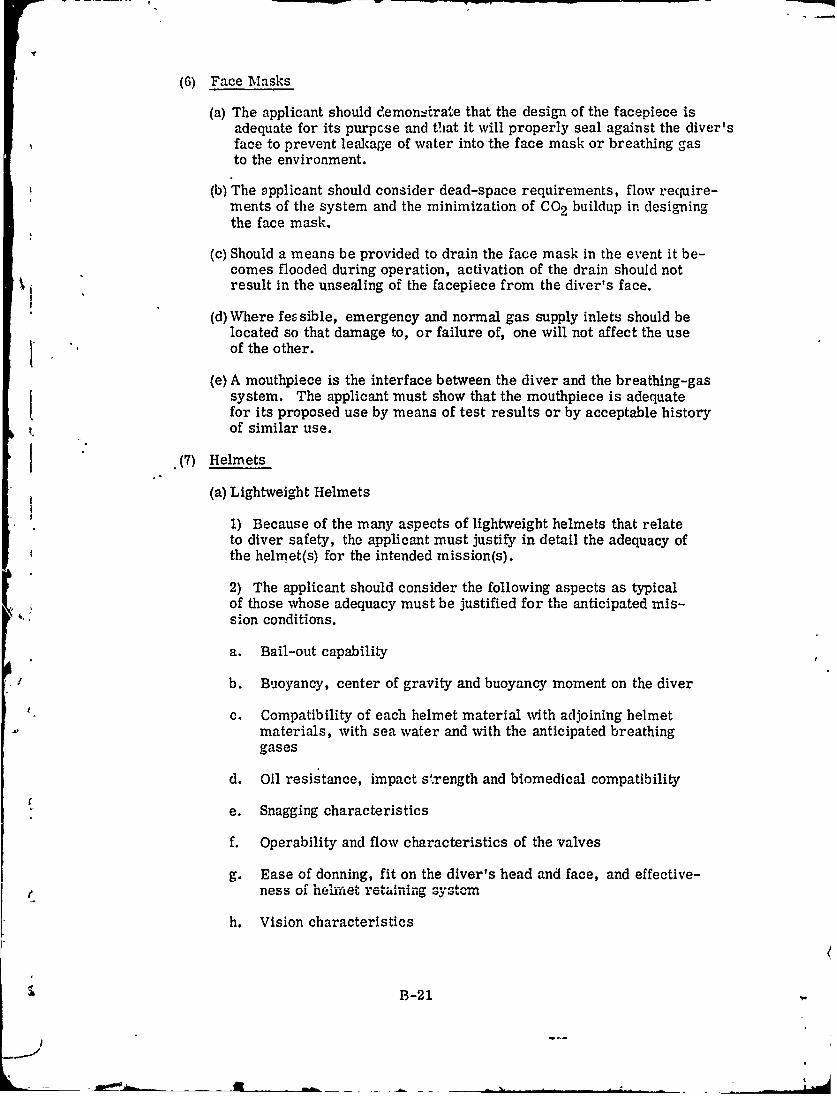
(6) Face Masks
(a) The applicant should demonArate that the design of the facepiece isadequate for its purpcse and that it will properly seal against the diver'sface to prevent leakage of water into the face mask or breathing gasto the environment.
(b) The Dpplicant should consider dead-space requirements, flow require-ments of the system and the minimization of CO 2 buildup in designingthe face mask.
(c) Should a means be provided to drain the face mask in the event it be-comes flooded during operation, activation of the drain should not
11 result in the unsealing of the facepiece from the diver's face.
(d) Where feG sible, emergency and normal gas supply inlets should be
located so that damage to, or failure of, one will not affect the use* "of the other.
(e) A mouthpiece is the interface between the diver and the breathing-gassystem. The applicant must show that the mouthpiece is adequatefor its proposed use by means of test results or by acceptable history
. of similar use.
(7) Helmets
(a) Lightweight Helmets
1) Because of the many aspects of lightweight helmets that relateto diver safety, the applicant must justify in detail the adequacy ofthe helmet(s) for the intended mission(s).
2) The applicant should consider the following aspects as typicalof those whose adequacy must be justified for the anticipated mis-sion conditions.
a. Bail-out capability
b. Buoyancy, center of gravity and buoyancy moment on the diver
c. Compatibility of each helmet material with adjoining helmetmaterials, with sea water and with the anticipated breathinggases
d. Oil resistance, impact s.rength and biomedical compatibility
e. Snagging characteristics
f. Operability and flow characteristics of the valves
g. Ease of donning, fit on the diver's head and face, and effective-ness of fi..e' retaining GYM.--
h. Vision characteristics
B-21
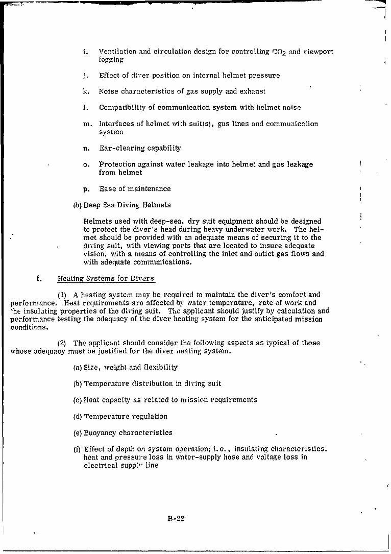
i. Ventilation and circulation design for controlling r02 ,!nd viewport
fogging
j. Effect of diver position on internal helmet pressure
k. Noise characteristics of gas supply and exhaust
1. Compatibility of communication system with helmet noise
m. Interfaces of helmet with suit(s), gas lines and communicationsystem
n. Ear-clearing capability
o. Protection against water leakage into helmet and gas leakagefrom helmet
p. Ease of maintenance
(b) Deep Sea Diving Helmets
Helmets used with deep-sea, dry suit equipment should be designedto protect the diver's head during heavy underwater work. The hel-met should be provided with an adequate means of securing it to thediving suit, with viewing ports that are located to insure adequatevision, with a means of controlling the inlet and outlet gas flows andwith adequate communications.
f. Heating Systems for Divers
(1) A heating system may be required to maintain the diver's comfort andperformance. Heat requirements are affected by water temperature, rate of work andhe insulating properties of the diving suit. The applicant should justify by calculation and
pe-formance testing the adequacy of the diver heating system for the anticipated missionconditions.
(2) Thc applicant should consider the foiloving aspects as typical of thosewhose adequacy must be justified for the diver neating system.
(a) Size, weight and flexibility
(b) Temperature distribution in diving suit
(c) Heat capacity as related to mission requirements
(d) Temperature regulation
(e) Buoyancy characteristics
(f) Effect of depth on system operation; i. e., insulating characteristics,heat and pressure loss in water-supply hose and voltage loss inelectrical suppV' line
B-22
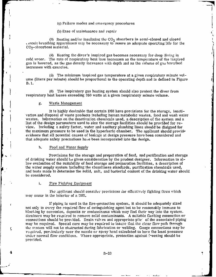
(g) Failure modes and emercency procedures
(h) Ease of maintenance and repair
(3) Heating and/or insulatina the CO 2 absorbers in semi-closed and closed,iruit breathing apparatuses may be necessary to insure an adequate operating life for theC02-absorbent material.
(4) Heating the diver's inspired gas becomes necessay.., for deep diving incold w, ter. The rate of respiratory heat loss increases as the temperature of the inspiredgas is lowered, as the gas density increases with depth and as the volume of ga breathedincreases with exercise.
(5) The minimum inspired gas temperature at a given respiratory minute vol-unie (liters per minute) should be proportional to the operating depth and is defined in FigureB. 1.
(6) The inspiratory gas heating system should also protect the diver fromrespiratory heat losses exceeding 350 watts at a given respiratory minute volume.
g. Waste Management
It is highly desirable that certain DSS have provisions for the storage, inacti-ration and disposal of waste products including human metabolic wastes, food and wash waterwastes. Information on the deactivation chemicals used, a description of the system and alist of the design parameters used to size the storage facilities should be provided for re-view. Including a safety factor, water and sanitary plumbing lines should be disigned forthe maximum pressure to be used in the hyperbaric chamber. The applicant should provi-devidence that all potential causes of leakage at design pressure have been considered andthat adequate safety precautions ha.e been incorporated into the design.
h. Food and Water Supply
Provisions for the storage and preparation of food, and purification and storageof drinking water should be given consideration by the prudent designer. Information to al-low evaluation of the suitability of food storage and preparation facilities, a description ofthe water supply system including the cleanliness standards, purification chemicals used,and tests made to determine the solid, salt, and bacterial content of the drinking water shouldb, considered.
i. Fire Fighting Equipment
The applicant should considee provisions ;or effectively fighting fires whichmay occur in the interior of a DSS.
If piping is used in the fire-protection system, it should be adequately sizednot only to carry the required flow of extinguishing agent but to be reasonably immune toblocking by corrosion, deposits or contaminants which may find their way into the system.Strainers may be required to remove solid contaminants. A suitable flushing connection orconnections should be provided. Drain valves and appropriate pit' of the associated pipingmay be required. Special care may be required to instire tla t th11,,c c.a.. flo.. path through
f, the system will not be obstructed during fabrication or welding. Gauge connections may ber,.quired, pari.icularly near the nozzle or spray head calculated to have the least pressureunder normal flow conditions. Where appropriate, protection against -- eezing should beprovided.
B --23
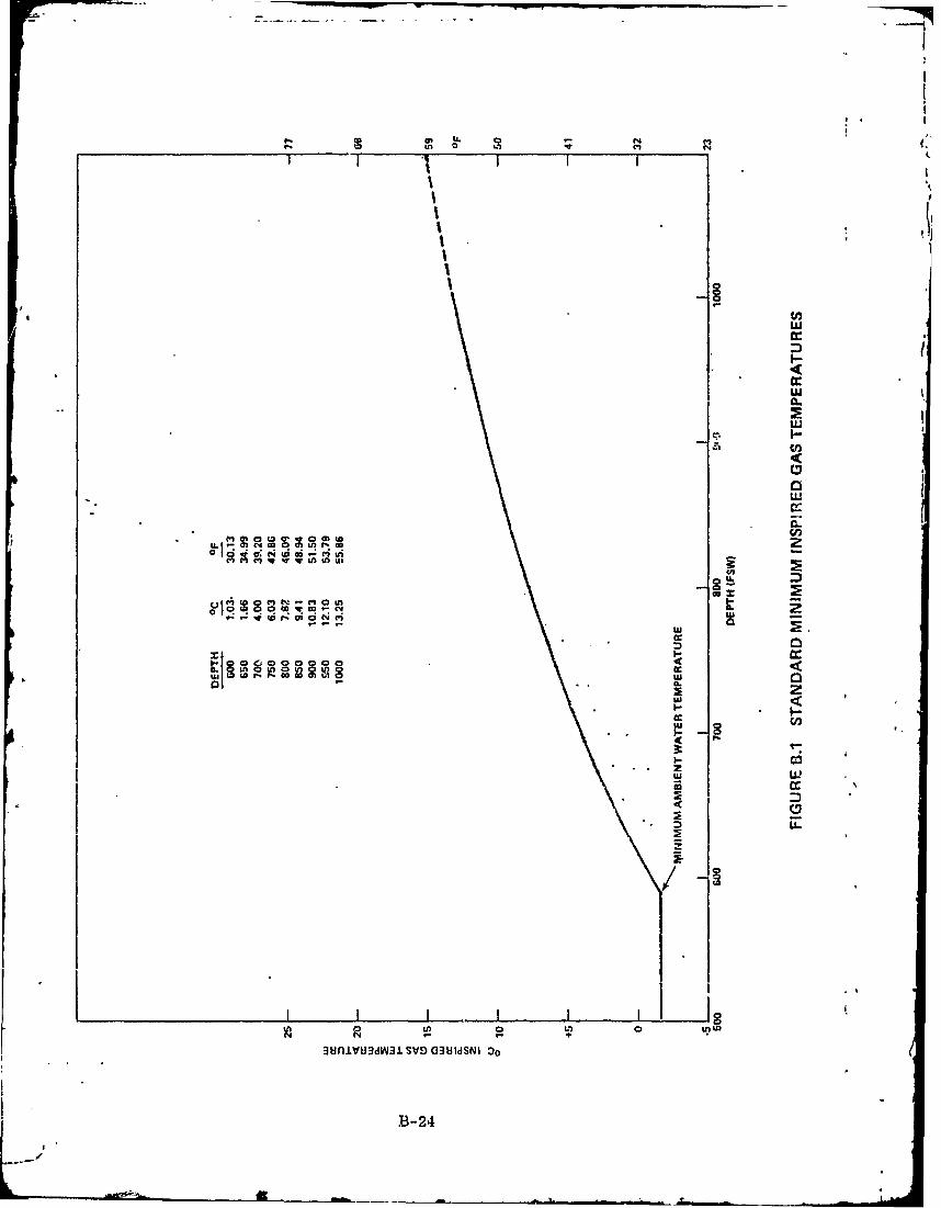
LL.1
o~ U. - N
W 0 N
I I6
IcI4ICIcILIcIc
C.) 10 w 9) u
UAU
--- CL20
A
zz
cc
D LL
awniv~dW3SVDa3UISISNI 00
B-2
j. C' mmunicaLion Equipment
Co'braun!cation facilities, such as radio equipment, underwater foiephonesand hollum sp,.:. h unscramblers, should be provided that are compatible with marinecomrmunicatioa equipment for rescue and emergency communications.
he applicant should consider the necessity for a voice communication systemthat wil perrn. DSS personnel and divers to communicate quickly with support personnel orwith other divers.
Visual communication systems, such as lights and message boards, may berequired. The applicant should specify the distance and water conditions for which thesesystems are appropriate.
B. 5 TOXIC AND FLAMMABLE MATERIAL DESIGN CONSIDERATIONS
a. Toxic Materials
Materials, such as paints, insulation, adhesives, or equipment, instruments,fittings or other items containing material or components that would give off noxious fumesat its operating temperature or at any temperature below 200°F should not be installed or
applied in manned spaces. For paint or adhesives, this requirement applies after dryingor curin:'. Air sampling and analysis of the DSS's atmosphere for trace contaminants (seeAppendix F for Guidelines) must be performed during simulated closed hatch operations toverify the above.
Mearcury and beryllium or parts or components containing these metals shouldnot be used in nor introduced into a DSS.
b. Flammable Materials
Every effort should be made to reduce or eliminate flammable materials from, ' manned spaces. Flammable materials include materials in a form which will ignite or ex-
plode from an electric spark or from heating and which if so ignited, will independently sup-port combustion in the presence of air or in an oxygen enriched atmosphere that might beencountered in the DSS under either normal or emergency conditions. A list of all Imown[ flammable materials must be forwarded for SCA review.
Magnesium and alloys containing magnesium should not be permitted insidethe chamber because of their combustibility. Materials or combinations of materials thatmay produce sparks when struck together should not be used inside a DSS chamber. Forinstance, magnesium, aluminum and the,: alloys can produce sparks when struck agair.strusty steel.
1Use of aluminum inside a steel chamber, or one having a steel floor, shouldhe shown to be nonhazardous. Aluminum and Its alloys should not be used for movableequipment, such as chair or cabinets, in a chamber with an exposed steel deck. Draggingequipment across the deck may remove by abrasion small particles of aluminum whichmay mix with rust to form a thermlte mixture, thus creating a fire hazard.
DSS furniture, such as bunks and chairs, should be electrically conductiveto minimize the probability of accumulation of a static electrical charge. However, theseitems should not be made of aluminum. Although bare aluminum is conductive, it tends to
B .i
A
lemIce e n-._,htl. stains on hands and clothing. Consequently, most aluminum that is to behandl-d is ano-iized. This anodized .inish is highly insulating and blocks the desired electri-cal discharge path.
If aluminum paint is used inside a DSS, precautions should be taken Lo insurethat it is not applied over rusted steel. A primer, not containing red lead or iron oxide,shou!d be used under the aluminum paint.
The applicant should provide sufficient information to permit an independentevaluation of the suitability and adequacy of the materials used.
B. 6 DESIGN OF CONTROL SYSTEMS, ELECTRICAL POWER DISTRIBUTION SYSTEMS
AND LIGHTING SYSTEMS
B. 6 Introduction
This section covers general design criteria of control systems, electrical powerdistribution systems and lighting systems that are within the certification scope.
B. 6.2 Control Systems
The applicant should furnish detailed design information for the respective controlsystems and components. This information should clearly discuss the liability of the sys-tern in the intended environment (e.g., temperature, pressure, humidity, etc.). Systemdescriptions should be furnished for all control systems. In addition, the system descrip-
tions should include an analysis of the consequences of a failure or loss of normal mode, anddescribe automatic and manual backup control features available for emergency recoveryor surfacing procedures. Test data in support of system and component reliability for in-tended service should also be provided. Design information and test data should be in suffi-cicnt detail to permit an independent evaluation of the adequacy of the controls, in theirenvironment, under all emergency operation conditions.
A control system is considered to be made up of three parts. The first part, the I Ipower supply, -is the source of power from which the control derives its energy. Thesecond part, the instrumentation, are the devices used to measure the variable beingcontrolled, the devices used to measure the response of the control system and/or thedevices used to provide necessary information to determine when the control should beactuated. The third part, control activators, are comprised of the devices which ac-complish the desired control function.
a. Power Supply
Control power supplies may be manual, mechanical, pneumatic, hydraulicor electrical. The choice thould be based on reliability in the environment in which thepower supply must function. The applicant should furnish information which substantiatesthe reliability of the power supply in tlhe intended environment. This information may bebased either on previous use of the power supply or on tests.
Electrical equipm it shlould be protected pgainst voltare variations in thepower supply and against excessh e flow of current when such occurrences present ahazard--direct or indirect--to the DSS or to a diver.
B-26
All controls should have two independent sources of power. For purposes ofdl.; :u'ssion, the.,e .Jternate sources of power are to be termed normal power and emergencyp..,.':-r. Failure of or, of the power sources should in no way hinder the use of the other 4power source, The emergency power source should be located such that it has as high adt:,,ree of sur'ival as the personnel. In instaces where redundant or backup electricalcontrol circuits are provided to external equipment or safety devices, the circuits shouldb2 routed througb different pcnetrators for maximum reliability. The emergency 'owershould have, as a minimum, sufficient capacity to permit operation of systems and instru-mn -itation to allow the DSS to safely ascend from maximum operation depth/pressure totht: surface equivalent and to maintain the DSS at the surface equivalent. A load analysisshould be furnished in sufficient detail to justify the power source capacity. This analysisshould cover all possible combinations of power use.
Power supplies for diver electrical equipment - usually located on shore orship, or.in a habitat or personnel transfer device - are not considered as items of diverequipment. However, the applicant may consider rechargeable batteries as diver-mountedpower supplies. Such a power supply should not be susceptible to power leakage.
Any electrical equipment to be carried or used by the diver should be specifi-cally listed. The applicant should show that adequate precautions have been taken to pre-vent hazards.
b. Instrumentation
Instrumentation requirements in a DSS will vary widely depending upon depthand exposure times. For complex diving procedures, substantial instrumentation may benecessary. For short and shallow dives, less complicated instrumentation may be required.Generally, instrumentation includes all sensors, warning devices, and displays that arewithin the certification scope. Instrumentation may include, but not be limited to, thefollowing:
(1) Carbon-dioxide sensors
(2) Oxygen sensors
(3) Gas-flow sensors
(4) Physiological sensors
(5) Electrical-defect detectors
(6) Heated-suit sensors
(7) Respiratory gas-temrerature sensors
(8) Low-pressure warning devices
All instrumentation should provide response commensurate with the avoidanceof hazardous conditions. The equipment should be electrically isolated from the DSS person-nel and should not be subject to erroneous readout. The applicant should show that the equip-ment has sufficient accuracy and will operate satisfactorily within the range of design para-meters. The applicant should specify the required accuracy of the measuring device con-sistent with control requirements.
B-27
T addition, the test ctt-a should be furnished which establishes the ability ofth,, mea.,,rin . device to i,,eet the act.uracy requirements in the intended environment. Allm1casurin de:'ces used to control siould have a backup ,means for providing meoisurements.Failure of one measuring clvicc should in no way impair the use of the other.
c. Control Actuators
The control actuator is any device or group of devices used to accomplish adesired control function. From a certification standpoint, the basic design goal of any con-tro! ssstem within ': certification boundary is reliability. To obtain reliability, the designshould be such that the control actuator is not subject to false alarms or extraneous signalswhich produce undesired responses. Switches and controls that are used to mnually ener-gize a control actuator should be located so that they are not inadvertently energized.
Control actuators should be designed to fail safe. This is, failure of any por- (tion of a control actuator should not in any way diminish the ability of the DSS to return tothe surface. Indication of malfunction or failure in a control actuator should be providedto the operator or diver.
Individual control actuators should be capable of being isolated from othercontrol actuators which share a common power supply. For electrical control actuators,this requires either fuses or circuit breakers on all lines connecting the control actuatorto the power supply. For hydraulic or pneumatic control actuators, this requires appro-priate check valve or valve isolation on all lines connecting the power supply to the controlactuator.
Where a control actuator energizes more than one device to accomplish thedesired control function, each device should be capable of isolation from the remainingdevices. For electrical devices, this requires circuit protection for both supply and re-turn Lines as well as a device that can manually disconnect the load. For hydraulic andpneumatic devices, this requires appropriate check valves or isolation valves on supplyand return lines.
Where a control actuator normally operates automatically, provision shouldbe made to allow the operator or diver to manually control the actuator. The manual con-trol should bypass as much of the control system as is practical.
B. 6. 3 Electrical Power Distribution Systems
a. Ungrounded Systems
All electrical power distribution systems should be ungrounded to minimizeshock ,.dn fire haz.ards. Equipment connected to the power distribution system should notground die power distribution system. All equipment designed te employ chassis groundsshould be isolated from the electric power system by a transformer or suitable isolationdevice. To minimize corrosion due to electrolysis, the use of the hull/vessel as ar elec-trical conductor or as a common reference should be avoided. For information relativeto performing insulation resistance tests on electrical systems, see paragraph 6. 3. 3.Ground detectors should be provided when possible.
b. Fault Current Protection
Fault current protective de-ices bhould be provd,, for each, unit of r'lectric
generating equipment or power supl),y and for each unit of power consuming equipment
B-28
4,e
connected to the distribution system. The design of the fault current protectix e devicesshould meet the btsic requirements of Section 21. 57 of AIEE Standard No. 45, "RecommendedPractice for Electric Installation on Shipboard."
c. Cabling
Cable subject to deep submersible pressure should be either compensated orhave a solid core construction. In addition, cable runs for individual feeders should beselected so that the effect of an3 fire damage due to a fault will be minimized with respectto damaging other cabling in the distribution system. Cable and wire housed inboard shouldbe arranged or protected to eliminate damage during entry into. egress from or normalpersonnel movement within a DSS chamber. During DSS construction, installed cablesshould be protected against mechanical damage, burning by welders torches, and contactwith oils and solvents. All cables terminating in pressure type connectors should haveconnectors applied in such a manner as to exclude all voids from the cable-connectorassembly and to impose no undue mechanical stresses to minimize cable flexing duringDSS transport and operations. A means of support should be provided at the cable/pluginterface to minimize bending during DSS operation. Sufficient slack should be left in thecable at penetrators to permit plug-in and disconnect operations without stressing thecable excessively.
Cables and wires should be protected against damage by accidental contact,crushing, shearing or being used as a handhold. Cables should be nonvicking and shouldbe shown to be capable of withstanding the operating pressure plus a safety factor.
Conductors should be flexible and easy to handle. Sufficient slack shall beleft in the conductor at penetrators to permit plug-in and disconnect operations withoutexcessive stress. Conductors should be supported, where possible.
Particular care should be taken in the case of portable electrical equipmentto protect conductors from excessive flexure, kinking, tension, being caught between mov-able objects or being stepped on. Conductors should be resistant to such abuse.
Conductors within cables should be electrically insulated from each other,from the DSS and from the diver.
Electrical insulating materials should be selected on the basis of their abilityto insulate the DSS equipment and to provide the proper functional and mechanical character-istics. Also, electrical insulating materials should be non-flammable and non-toxic. Examplesof electrical functional characteristics are dielectric strength, insulation resistance and arcresistance. Mechanical properties include impact strength, tensile strength, elongation,flexibility, adhesion and abrasion resistnce.
Connector design should permit the DSS operator or diver to disconnect theumbilical and any other electrical conductor readily without receiving an electrical shock.Electrical connectors should be sealed against water at operating pressure.
All cables terminating in pressure-type connectors should have connectorsapplied in such a manner as to exclude all voids from the cable-connector assembly andto impose no undue mechanical stresses on conductors or connections.
The materials and mothods used to join connectors and fittings to umbilicalcables and hoses should provide a strong bond capable o.f withstanding severe handling andoperating conditions.
B-29
Conn,"ctor pins and soc<ets should be corrosion resistant or plated to preventcorroson and electrical discontinuities.
Electrical connectors should be designed to prevent incorrect connection. Thismay bo accomplished by size selection, key fit or other means. Color coding oc- other visualidentification alone is usually insufficient. Electrical connectors should also be designed toprevent accidental disconnect.
d. Electrical Shock Hazards
All electrical powered equipment or enclosures should be adequa ly groundedso as to prevent shock hazards to personnel.
e. Enviconment
The environment for electrical components that are used on DSS (e. g., cabling,connectors, protective devices, motors, power supplied) may differ markedly from normalshipboard conditions. The components may be oil immersed, subject to full sea pressure,operate at low temperatures, subject to high vibration, high humidity, etc. The applicantshould furnish specific test information which justifies the ability of the electrical compo-nent to function in the intended environment for its design life or over the design range ofpressures, temperatures, humidities, voltafges, etc. For flammability and toxic consid-erations see Appendix B. 5.
Materials used in electrical equipment should be shown, by test or experience,to be resistaht to deterioration by the environment, by migration of a plasticizer or by theexternal application of heat.
f. Electrical Penetrators and Connectors
The body of electrical pressure vessel penetrators and connectors exposed tosea water should be of a corrosion resistant material.
Electrical cable pressure vessel penetrators must provide high water barrier atthe hull to prevent flooding of the DSS in the event of failure of the external cable. Stuffingtube type penetrations of the pressure capsule or other hard structure are not generallyacceptable. Pin type connections for cable entrances into compensated enclosures are pr9 -fer ed; however, terminal tube entrances are acceptable provided evidence of compatibilityof the cable jacket and insulation with the compensating medium is provided.
Since the electrical hull penetrator is part of the primary pressur boundary,data ,hould be pro% ided to assure that its hydrocyclic life is defined in relation to the des k, ilife of the hull.
Provisions shall be made to protect the pressure vessel from corrosion in thegasketed areas of the penctrators.
B. 6.- Lighting System.3
The lighting system should have an alternate source of power or emecgency lampsshould be provided. These lamps are backup in the event of total loss of th normal light-ing system. The capacity and location of the a*turnate power suIH' .. 1 ,
of the emergency lamps should be specified.
B-30
* I- ~-
B.7 NAVAL ARCHITECTURE DESIGN GENERAL REQUIREMENTS
The naval architectural requirements that the applicant should consider are at thel...st; static stability, both transverse and longitudinal, the conditions of list and trim, thest.,.,ngth ,t the DSS and the dynamic considerations of stability and motion of the DSS amongwaves .
B, 7. 1 Stability of a DSS
The applicant should demonstrate, where applicable, both by calculation and bytests, that a DS has adequate static and dynamic stability under the various loadings andconditions encompassed by the design (e.g., surfaced, submerged and all possible emer-gency surfacing conditions). The designer should also identify any liiting .conditions forsea state, winds, temperatures, water density variations, etc. Extreme loading conditionsand the resulting utability should also be analyzed. For example, some I'SS jettison rela-tively large weights to achieve buoyancy in an emergency. There is an attendant risk thatsignificant weights might be jettisoned inadvertently while in normal operations. The ap-plicant should show that the DSS would have adequate stability under these conditions also.The criteria of adequate stability and reserve buoyancy with sufficient information pertain-ing to stability must be furnished to operating personnel to permit proper control of load-ing and to avoid danger of capsizing or foundering in heavy seas or swells.
B. 7. 2 Surfaced Conditions
There are periods when certain DSS will be operational in a surfaced condition Inthe limiting sea state and wind conditions specified-by the applicant. The applicant shouldshow that the DSS is safe for emergency egress under these conditions. The applicantshould also demonstrate that the DSS is adequate to withstand such factors as wave slapand that th2 strength of the structure of the DSS is adequate in the surfaced condition.Protection should be provided against foundering.
The DSS must be designed to operate on the surface in the most severe sea condi-tions specified by the applicant or the designer.
B. 7. 3 Inclining Experiments and Trim Dives for Submersibles, Submerged Habitats, Etc.
If the DSS is of such complex geometry that reliable curves of form cannot be readilycalculated, air, surface and submerged inclining experiments must be performed to deter-mine the stability in the surfaced and submerged modes. Precalculated form characteristicsob, iate the need for an air inclining experiment, hence the surfaced and submerged incliningexperiments are sufficient to determine the stability surfaced and submerged when curves ofform are available. Where the DSS vessel is not too large the longitudinal trimming momentcould be determined by direct measurement or by a longitudinal inclining experiment. Inaddition, a trim dive is necessary to determine the proper weight and location of ballast,both permanent and variable, that will permit the vessel to operate under the design condi-tions of loading and in water of any density. The applicant should submit the inclining ex-periment and the trim dive results with the evaluation of the stability of the vessel.
B. 7. 4 Damaged Condition Information
The damaged condition criterion for a DSS design should be identified. The abilityU of a DSS to survive within the damaged condition criterion should be verified by calculation
and testing, where possible. When "at-sea-testing' u- a UDSo systo.m and/or componentsis impracticable, simulated tests using appropriate test fixtures may be substituted. The
B-3t
means of detecting an abnormal situation or detecting a damaged condition should be evalu-ated. The cor :ective action intended by the designer should be implemented by writtenoperatiniz procedures. These actions should be demonstrated in simulated damaAed con-ditions. The purpose of the demonstration is too verify the effectiveness, timeli:.ess andrealism of the proposed corrective actions established by the designer.
B. 7.5 Strength of DSS
rhe applicant must show that the structural strength of certain DSS in a seaway doesnot endanger tho safety of personnel. A DSS may operate in close proximity to bhe oceanbottom. This means that there will be a ha-zard of striking objects, grounding or even de-liberate bottoming. There is also the hazard of bumping against or colliding with the sur-face support ship. The applicant should either show that a DSS can withstand such incidentor demonstrate that sufficient precautions can be taken to avoid such situations.
B. 7.6 Navigation Systems
Navigation equipment should enable the DSS operator or the diver to direct hiscourse safely during operations. System accuracy should be based on worst-case oper-ating conditions. An alternate or redundant mode of operation should be provided. Cer-tain DSS should be provided with suitable navigation lights, where and when required.
'B.7.7 Rescue Features
The features of the rescue capabilities included in the DSS design should be pre-sented by the applicant. The DSS should be provided with the capability of being lifted forrescue or for recovery when flooded. As appropriate, a specific rescue plan should beincluded showing the intended means to accomplish rescue in the event of an accident whilesubmerged. The iimiting conditions for each of these operations should be included. Theapplicant should also state whether or not the DSS is compatible with existing U. C. Navyrescue and salvage equipment.
B. 7. 8 Stability and Buoyancy Systems
The applicant should identify the systems and components that provide any necessarystability and buoyancy for the DSS under operating conditions. An analysis of the conse-
L ices of a failure or loss of displacement by any of the buoyancy components should beincludedd. The adequacy of specific materials should be justified as discussed in Appendix A.
B-32
APPENDIX C
DESIGN PARAMETERS FOR IMPLODABLE ITEMS
C. I INTRODUCTION
This appendix contains guidelines on how to determine the criticality of systemsand/or components which may implode and cause a casualty that would affect the safetyof DSS personnel. Implodable systems and/or components exclusive of pressure hull/vessels and hard structure are divided into two categories:
I - Critical Volumes
II - Non-Critical Volumes
C. 2 DEFINITIONS
a. Implodable Item - Any item containing a non-compensated compressiblevolume subject to full pressure.
b. Critical Volume - Any implodable volume which by imploding could causea casualty to the DSS and/or which would affect the safety of DSS personnel.
c. Standoff Distance - The measured closest distance between the outer surfaceof the implodable item and the outer surface of the pressure hull/vessel component and/orsystem which could affect the material adequacy of the DSS.
d. Minimum Standoff Distance - The minimum distance at which an implodableitem can be located such that if an implosion occurs it would not affect the material ade-quacy of the DSS (see Procedures C. 3.2 below).
C. 3 CRITICAL AND NON-CRITICAL VOLUMES
C. 3. 1 Method for Distinguishing a Critical Volume from a Non-Critical Volume
If an implodable volume is "non-critical" the testing as indicated in C. 4 may not benecessary, subject to the SCA approval. Application of this method for distinguishing"critical volumes" and "non-critical volumes" is limited tu the situation where the pressure
- bll is spherical. Additionally, even though the DSS pressure hull is spherical this methodmay not be applied (i. e., testing as indicated in C..1 must be folloed) in the following cases:
a. Spherical pressure hulls/vessels with a design crush depth of less than 1. 5times the design depth.
b. Pressure hulls/vessels which are not designed to withstand ambient exter-nal pressure and 1 arm internal pressure.
c. Pressure hulls/vessels fabricated from a brittle material (e.g., glass,ceramics).
Procedures to cover these conditions should be generated by the applicant, as applicable.
C-i
C.3.2 Prochdurcs for Determining Minimum Standoff Distance from a Spherical DSSChmnber
a. Calculate the "minimum standoff distance" in feet as described below:
(1) Calculate the volume of the shell or pressure housing of the implodable item.
(2) See figure C. 1 with implodable volume and maximum design depth/prcs-sure to obtain a "k" factor.
(a) If the depth/pressure is not exact take the next shallow,r depth/lower pressure te. g., assume design depth 3500 feet in this case take 3000 feet).
(b) Any depth between 0-500 feet should be based on a 500 foot curve.
(c) If the implodable volume is less than 10 cubic inches assume avalue of 10 cubic inches.
(d) If the implodable volume is greater than 1000 cubic inches, or depthis -eater than 8,000 feet, testing indicated in C.4 shall be followed to assure the materialadequacy of the item.
(3) Multiply the k factor by I/-V\"where r is the radius of the pressure hull/sphere in feet.
(4) The result will be the "minimum standoff distance" in feet.
b. If the "minimum standoff distance" is greater than either:
(1) The actual standoff distance between the implou ible item and the pressuresphere or
(2) The actual standoff distance between the implodable item and any systemor components which if failed would affect the material adequacy of the DSS, then the im-plodahle item is considered to have a "non-critical implodable volume."
c. If the "minimum standoff distance" is less than both:
(1) The actual standoff distance between the implodable item and the pressurehull/vessul sphere and;
(2) The actual standoff distance between the implodable item and any systemor components %%hich if failed would affect the material adequacy of the DSS; then the im-plodable item is considered to have a "non-critical implodable volume."
d. If the implodable item is found to have a "critical implodable volume," testingindicated in C. .1 shoul.: be followed to assure the materia! adequacy of the item.
e. If the item is determined to have a "non-critical implodable volume" and it isthereore not considered necessary to test the implodable item to the requirements indicatedin C.4, then, subject to the SCA's appro al, testing ay be eliminated., In this ease, thefollowing information is required:
C-2
a __
(1) Sketches or photographs in the three mutually perpendicular planes des-cribed by x, y, z coordinates, showing the orientation of the implodable item with respectto all systems or components affecting the material adequacy of the DSS, for a distance of3 "minimum standoff distances" in every direction from the implodable item.
(2) A general description (e.g., geometry, material) of the implodable item.
(3) Test depth and/or designed depth of the implodable item.
(4) Calculations of volume and "minimum standoff distance."
C. 4 TESTING NECESSARY FOR "CRITICAL IMPLODABLE VOLUME"
The following tests are required for all implodable items considered by the SCAto have a "critical implodable volume."
a. Prototype testing necessary for implodable items fabricated from Category 3
materials (e.g., R&D prototype items).
(1) Static strength test (2 times maximum operating depth).
(2) Fatigue test - Full anticipated life cycle times four.
(3) Stress corrosion in sea water (run concurrently with fatigue test).
(4) Temperature and tightness test.
(5) Strength test prototype pressure container to collapse (in sea water) -Determine failure mode.
b. Testing necessary for all "critical impiodable volumes" and "non-critical volumes"not treated as in paragraph C. 3.2. e.
Submergence Pressure Test (Category 1, 2 and 3 components) to 1-1 1/2 timesdesign operating depth for 10 cycles; 10 minutes at greatest pressure - cycles 1-9, 1 hourat greatest pressure - cycle 10, (35°F sea water if practicable).
Leakage or visible signs of external damage shall be cause for test failure.
C-3
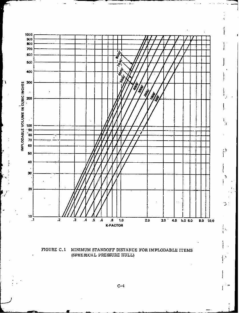
10
900
4A 00
3200-u
20
>100
-so
7. 0
0
20 ___
.1 2..0. 5 .6 . 10z 3.0 4.0 5.0- 6.0 8.0 10.0
K-FACTOR
FIGURE C.-1 MINIMUM STANDOFF DISTANCE FOR IMPLODABLE ITEMS(SPHERICAL PESSURE H-ULL)
.
C-4
.1M[NIMUM STANDOFF DISTANCE FROM A SPHERICAL DSSFOR AN IMPLODABLE CAMERA CASE
)T
F- ... 16"1
CALCULATE INSIDE VOLUME
2V = IT (3/2) X 16
V = 1r (9/4) X 16 = 36 X =113 CUBIC INCHES
= 2. ENTER GRAPH UNDER MAXIMUM DESIGNED DEPTH OF 6000' AND VOLUMEOF 113 CUBIC INCHES TO GET K-FACTOR.
~~K -,.85
3. iULTIPLY K-FACTOR BY WHERE R IS THE PRESSURE HULLRAD)IUS IN FEET. -,r
R = 3.5--. (3.5)1/2 = 1.87
.85MINIMUM STANDOFF DISTANCE 1.87 455
MINIMUM STANDOFF DISTANCE -5-1/2"
A THIS IS THE MINIMUM STANDOFF FOR CONSIDERING ANITEM OF "NON-CRITICAL VOLUME". TESTING PER PARA -GRAPH C. 3 WOULD NOT BE REQUIRED AS LONG AS THE'HULL STANDOFF IS GREATER THAN 5 1/2" AND THE ITLMIS NOT LOCATED WITHIN 5 1/2" FROM ANY CERTIFICA7IONSCOPEITEM.
a Figure C. 2 SAMPLE CALCULATION (ASSUME SPHERICALDSS HAS 6000 FT. MAXIMUM DESIGN DEPTH)
C-5/(C-6 blank)
.4"
APPENDIX D
DESIGN PARAMETERS FO. EKPLODABLE ITEMS(I
D. 1 INTRODUCTION
During the design process particular attention shall be given to the shock effectsproduced by the explosion of items within the DSS.
Many devices- are subject to inadvertent explosion during decompression becausethey have been infiltrated by helium or other gases during a compression cycle. Thesedevices, in themselves, may become hazards within the DSS and should be consideredduring the design process.
At the present time there is no known analytical method for determining the mate-rial adequacy of items within a DSS which may explode and cause a casualty. Therefore,in order to achieve a maximum reasonable level of assurance for these items this appendixcontains guidelines to determine their material adequacy.
D. 2 DESCRIPTION AND ORIENTATION
Data of the manned DSS spaces should be reviewed to determine and describe thet-size, quantity and locations of all explodable volumes. Representative samples of these
items should be selected based on the following Sampling Table and subjected to the testprocedure.of D. 3.
( Lot Sampling Table
Lots or Batch Size Sample Size
2 to 8 29 to 15 3
16 to 25 526 to 50 8
' ( 51 to 90 1391 to 150 20
D. 3 PROCEDURE
C. Each item selected should be tested as follows:
a. Subject the item to a pressurized helium soak test. The time of soak shouldbe not less than two times the maximum expected exposure period. The pressure shouldbe the maximum operating pressure.
b. Following the soak test, depressurize at a rate not less than 1.5 times-the
maximum depressurization rate of the manned space.
D. 3. 1 Acceptance Criteria
That items do not show evidence of physical deterioration should be cause foracceptance of all like items. Accepted items may be used in manned spaces.
D-1
D. 3. 2 Rejection Criteria
'rhat items show evidence of physical deterioration shall be cause for rejection of Uall I ike items.
D.3.3 Retest
Further analysis and/or retesting of rejected items will be subject to SCA approval.
D. 4 NON-METALLIC MATERIALS
It should be shown that non-metallic materials that are to be exposed to high-pres-sure helium do not deteriorate due to exposure to the maximum design rate of helium de-compression. f
I£1
D-2 t
li__..J
APPENDIX E
DEEP SUBMERGENCE SYSTEMS BREATHINGGAS REQUIREMENTS
E. I INTRODUCTION
The composition of breathing-gas and the quantity required are determined byphysiological characteristics of the human body.
The breathing mechanisms that serve to regulate partial pressures of oxygen andcarbon dioxide in the blood at sea level serve equally well under the sea if the partial pres-sures of oxygen and carbon dioxide, as well as the respiratory volume, are similar to
'1 "those at sea level. Sufficient information is known regarding physical tolerance to partial-pressure levels to permit safe selection of both com'nosition and volumes of breathing gasfor a DSS.'
J E. 2 BREATHING GAS CONS I PTION
Breathing gas is a mixture containing oxygen, part of which is consumed in respira--tion, and inert diluent gas, such as nitrogen or helium, that is not consumed or altered.The oxygen consumed in the body reacts with carbon and hydrogen to produce CO 2 and water.
-.The C02 and water (which appears as water vapor) thus formed are exhaled with the breathinggas. The volume fraction of C02 released relative to the volume of oxygen consumed varies'from 0.7 to 1. 1 depending upon the carbon-hydrogen ratio of food being metabolized, exer-tion history and other factors.
Figure E. 1 relates oxygen mass consumption rate and respiratory volume to rate ofexertion. The data for Figure E. 1 are based on experimental measurements (2,3)*provide a basis for selection of breathing gas quantities for DSS.
The mass rate of oxygen consumption and the corresponding carbon dioxide produc-tion rate vary with physical exertion but are independent of depth. As hidicated in FigureE-1, values of oxygen consumption vary from about 0.5 standard liters per minute (slm)when at rest, to about 4.0 slm with heavy exertion. These values are equivalent to 0.0895and 0.716 pounds of oxygen per hour, or 1. 14 to 9. 13-standard cubic feet (scf) per hour. **
S/ The volume of oxygen consumed decreases in inverse proportion to absolute pressure(depth) in accordance with-gas laws.
th |The values for respiratory minute volume (RMV) (the volume of gas moved throughthI lungs in one minute) show.n in Figre E-1 depend upon ventilation (removal of carbond.io:.%cl) requirements of the body. These volumes are tlhe same at all diving-depths. Thus,the mass flow of gas to meet ventilation requirements increases with depth (pressure) andwith oxygen consumption (exertion).
In demand-tvpe breathing apparatus, the averaged volumetric breathing gas supplyrate equals the RIM' requirement of 10 to 100 1pm (0.3 to 4 efm), depending upon the levelof exertion, measured at depth. The Instantaneous flow rates tend to conform to the user'sbreathing demands.
In closed-circuit rebreathing apparatus supplied with pure oxygen, the rate of oxygencon.umption is equaled by the rate of supply, all carbon dioxide bein-g absorbed in the recir-culation loop and no gas being vented from the apparatus. The oxygen mass consumption
R,- terene aCL "iven at th -nd of Appendix E.- 0 rece ae7Cw' a 0.
The s'tandard liter is defined ar 0°C (320F) and the standard cubic feet is defined at 60 F.Thus, although 1 ft 3 23. 3 liters, one stmdard ft3 26. 3 standard liters.
E-1
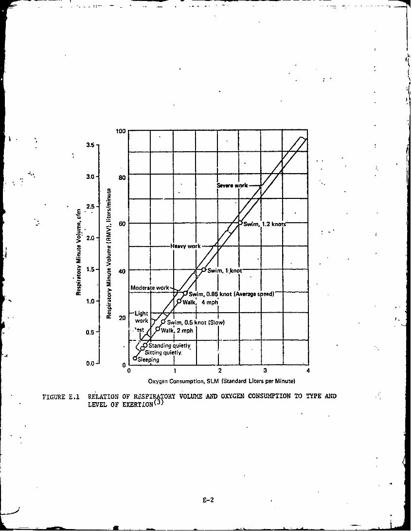
100
3.5-
3.0- soSevewr rk
2.5
E 60 -a-wSwi '.1.2 knt
-6> 2.0-
E. E-.
"1
40 s , I1.knT -Moderate work,
00.85 knot speed)
1.0 0
1 .2Walk3 4mph
2 Light f f~ 0 work Swim, 0.5 knot (Slow)
05- 'lest %Walk,'2 mph
Standing quietly
Sitting quietly
0 1 2 3 4
Oxygen Consumption, SLM (Standard Liters per Minute)
FIGURE E.1 RELATION OF RESPIRATORY VOLUME AIND OXYGEN CONSUMPTION TO TYPE'AND
LEVEL OF EXERTION(3)
E-2
-* - -
rate depen(k only upon the rate of exertion and is independent of depth (recognize, however,that it is necessary to maintain a certain minimum volume of gas in the recirculation loop).Oxyvgen consumption- rates can range from 0.5 to 3 slm, and an average value of 1.5 slmappears reasonable for planning purposes.
Semiclosed-circuit mixed gas breathing apparatus operate by chemically removingthe CO2 from most of the gas mixhire exhaled by a diver. This C02-free portion of theexhaded gas mixture, which is somewhat depleted of oxygen, is mixed with an inflowing gas tmixture that is rich in oxygen, forming a total mixture that is intermediate in oxygencontent. The oxygen content and the mass flow rate of the inflowing oxygen rich mixtureare preselected so that the oxygen content of the total mixture is, within acceptable limits,the same as that of the gas mix-ture that the diver had originally inhaled - this total mix-ture can now again be inhaled. The part of the gas mixture exhaled by the diver that stillcontains C02 is vented from the apparatus to make room for the inflowing oxygen rich gasmixture. In the particular semiclosed-circuit breathing apparatus used in saturation-divingexcursions, the oxygen rich gas mixture contains a 1.2 atm partial pressure of oxygen atthe diver's depth and the mass-flow rate is sufficient to provide for continuous exertion at3 slm oxygen usage. 'he oxygen concentration in the inhaled gas mixture varies -from about1.0 atm at rest to ,%. 21 atm during severe exertion. The vented gas contains oxygen atp,artial pressures varying from 0.8 atm at rest to 0.16 atm during heavy exertion. Themixture and mass flow rate of gas into the system are selected on the basis of depth andthe maximum short time oxygen partial pressure exposure allowable should the diver findit necessary to flood his apparatus with this oxygen rich mixture.
Certain DSS, such as habitats, chambers and the standard deep sea diving apparatus,dilute the &arbon dioxide rich exhaled gas in the system to bring it to non-toxic, breathe-able levels of 0. 01 to 0. 025 atm partial pressure of carbon dioxide. The required flow rateinto this type of system is similar to the RMV at maximum exertion. In these systems itis usual to supply at least 4.5 cfm- (127 1pm) of gas, per diver, measured at depth. Thiswould be sufficient to permit exertion levels corresponding to oxygen consumption of 1. 27slm- if carbon dioxide in the system is held to a -level of 0.01 atm partial pressure, or of3. 0 slm if carbon dioxide in the system is held to a level of 0. 024 atm partial pressure.
The surface-supplied helium-oxygen deep sea diving apparatus operates much likethe semiclosed-circuit apparatus in that breathing gas in the helmet is recirculated througha carbon dioxide absorber to minimize volumetric gas inflow requirement. Breathing gasis supplied from the surface through a hose at a rate of 0.5 cfm, measured at depth, andenters the helmet through an ejector which drives the recirculation -flow. With a recir-culation ratio of about 10, the ventilation effect is equivalent to 5 cfm or 140 lpm, which isadequate for heavy work. The oxygen content of the mixture is maintained ,t a high level
( and can be varied during the dive to suit depth and decompression requirements. If this-apparatus is used-at shallow depths with air, anoxia could result unless the flow rate intothe hcdlmet is increased to provide needed oxygen. The required -flow rate will reach 2.1scfm of air at the surface for oxygen consunption of 3 slm.
There are certain equipments in use that employ a-breathing -as flow to a-rigidhelmet or mask that does not possess-a flexible gas storage capability such as is providedby a breathing bag or as in the case of the standard deep sea-diving apparatus, the bib ofthe diver's dress. If the diver's physiological functions are not to be significantly affected,it is -necessary, in these equipments, to natch the gas flow rate into the helmet or maskwith the user's instantaneous peak inhalation flow rate. Information available at thiG timeplaces this flow rate in the neighborhood of 350 lpm- (12. 4 cfm) measured at depth.
F-3
.- ).

The efficiency of oxygen utilization or percentage of the oxygen supplied that isutilized, varie. with the type of DSS and with depth. When breathing air at sea level, oxygencontent is reduced from 20.8 percent in inspired air to 16.6 percent in vented air, utilizingonly 20.2 percent of the available oN:ygen. When using demand-type open-circuit breathingapparatus supplied with air, or with a gas mixture of constant oxypen content, the massflow of breathing gas, and of the oxygen in it, will increase with d while the oxygenconsumption remains constant. Thus, a lower percentage of the oxygen supplied will beutilized as depth increases. If, however, the breathing apparatus were to vary oxygencontent of the breathing gas with depth to provide a constant oxygen partial pressure, themass flow of oxygen supplied would be constant and the proportion of oxygen utilized wouldbe constant. In semi-closed breathing apparatus where oxygen is supplied at 1.2 atmpartial pressure, recirculated and finally vented at 0.166 atm partial pressure, 86 per-cent of the oxygen supplied is utilized during heavy exertion. Finally, with a closed sys-tem supplied with pure oxygen, all of the oxygen supplied would be utilized, since no gasis vented and the oxygen is recirculated until it is used.
TABLE E-1. EFFECTS-OF VARIOUS 02 CONCENTRATIONS
02 Concentration
Partial Pressure EffectAtmospheres
0.18-. 21 Normal sea-level conditions
0.16-. 12 Increased breathing- rate,lack of coordination
0.14-. 10 Easily tired; easily upsetemotionally; possible loss ofpain or injury; abnormal fatiguefrom exertion --
0.10-.06 Lethargic; apathetic; confusedthinking; physical collapse;possible unconsciousness, nauseaand vomiting
0.06 or less Convulsive movements, gasping,cessation of breathing
E.3 SURFACE BREATHING AIR REQUIREMENTS
The volume of breathing gas (air) needed for a DSS operating at one atmospheremay be determined using Figure E. 1 and taking into consideration the total of all aspectsof DSS personnel activity.
E. 3.1 Human Oxygen and Air Consumption
The normal oxygen control range should be 18-21%. Alarm set points should be17-23%. If the alarm limits are exceeded Immediate corrective action should be taken.(Because of fire prevention considerations, if the concentration of oxygen ever exceeds 25%or If the corrective action fails to return the oxygen concentration to within the limits theDSS should be immediately returned to the surface and ventilated.)
E-4
E, 3. 2 C02 Production Rates - Respiratory Quotient (RQ)
Respiration accounts for most of the carbon dioxide generated in a DSS. With anaVerage oxygen consumption of 1.0 SCFH (. 44 SLPM) per man, the corresponding averageCO. eneration rate has been observed to vary between 0.80 and 0.85 SCHF (0.352 and0.,- 0074 SLPM) dpending upon dietary considerations. This is equivalent to 0. 1 lb3. /man-
ho u. Since the speciic -gravity of CO 2 is equal to 1,53; the respiratory quotient, RQ, isecf.A to the volume of CO2 produced for each unit volume of 02 consumed.
The-efore:Volume of CO2 produced 0.85
.RQ= = 0.85Volume of 02 consumed 1
4 E. 3.3 CO2 Build Up
Without removal ecripment, CO2 concentration will increase In accordmas with the•, followving" formula:flwgoma(RQ) x 02 (Consumption rate) x T
% CO o.03+V/N
Where T Time, In Hours .V/N= Floodable Volume Per Man
( RQ = Respiratory Quotient-0.03= %.of CO2 in "Clean" Air
E. 3.4 Toxicity of Carbon Dioxide
In normal breathing, the concentration of oxygen in the breathing gas is reduced andthe oxygen is replaced by a nearly equal volume of carbon dioxide. If carbon dioxide isincluded in the inhaled gas, the partial pressure of carbon dioxide in the blood increases,and the respiratory center in the brain increases ventilation (tidal volume and/or breathingrate) to restore normal carbon dioxide levels. Excessive amounts of carbon dioxide in thethe partial pressure of carbon dioxide.
Figure E-2 shows the relation of physiological effects of carbon.dioxide for differentconcentrations and exposure periods. In Zone I no perceptible physiological effects havebeen observed. In Zone II small threshold hearing losses have been found and there is aperceptible doubling in depth of respiration. In Zone IH,° the zone of distracting discomfort,the sm-nptoms are mental depression, headache, dizziness, nausea, "air hunger, 11 anddecre-ase in visual discrimination. Zone IV represerts marked physical distress leadingto dizziness and stupor, with inability to take steps for self-preservation. The final stateis- unconsciousness.
The bar graph at the right of Figure E. 2, for exposures of 40 days, shows thatconcentrations of carbon dioxide in air of less than 0.5 percent (Zone A) cause no biochemicalor other effects, concentrations between 0.5 and 3.0 percent (Zone B) cause adaptive bio-chiemical changes, which may be considered a mild physiological strain, and concentrationsabove 3. 0 percent (Zone C) cause pathological changes In basic phsiological functions.
For nornml DSS-operaions, ,0. r0. _v . ._teshoId-he.rrovided that-resutIincarbon dioxide partial pressures corresponding to Zones I and II for short-term exposure,aid to Zones A and B for long-term exposures.
E-5
1-i
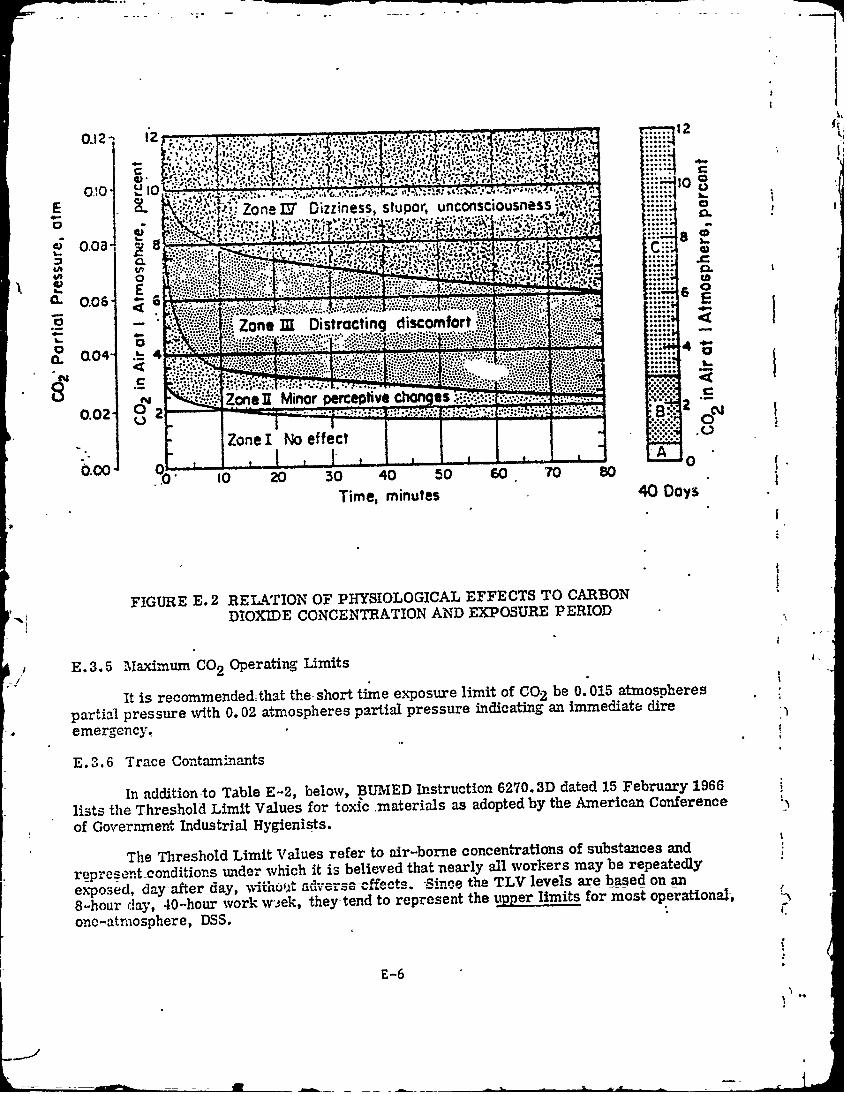
1.10
ZoL..T ne IVDizziness, stpr uno n
U'
Zon -3 Distracting disomfort.
................................ .....
N T~?~.ZoneH Mnor perceptive chnes 1i.0.02 2_ B:...
0 oa
Zonel I oeffect .. 0
_____ ,___I ___- _ _L -. " -j A 060 0I 20 30 40 50 s0 70 80
Time, minutes 40 Day's
FIGURE E. 2 RELATION OF PHYSIOLOGICAL EFFECTS TO CARBONDIOXIDE CONCENTRATION AND EXPOSURE PERIOD
E.3. 5 Maximum CO2 Operating Limits-I2
it is recommended- that the- short time exposure limit- of CO2 be 0. 015 atmospheres
partial pressure with 0. 02 atmospheres partial pressure indicating an immediate -dire
emergency.
E. 3.6 Trace Contaminants
In-addition to Table E-2, below, B3UMED Instruction 6270. 3D dated 15 February 1966
lists the Threshold Limit Values for toxic .materials as adopted by the American Conference
of Government Industrial Hygienists.
The Threshold Limit Values refer to air-borne concentations of substances and
represent-conditions, under which it is believed that nearly all workers may be repeatedly
exposed, day-after day, .,jjhfjA[ advrerse -Off-ects. Since the TLV levels are based on an
8-hour clay, 40--hour work w',,ek, they-tend to represent the uipper limits for most operational-,
one -atrio sphere, DSS.
E-6
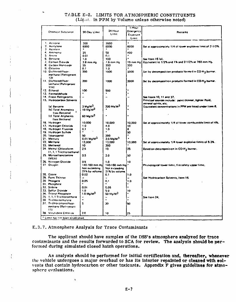
TABLE E-2. LIMITS FOR ATMOSPHERIC CONSTITUENTS(Lirit. in PPM by Volume unless otherwise noted)
I HourChemic.i SuIlttanco 90.Day Limit 24-Hour Emergency Remarks
Limit Exposure
Limit
1. Acetoie 300 20007. Ac.,tylene 6000 6000 6000 Set at approximately 1/4 of tower explosive lirmit of 2.1/2%.3. Acrnlein4. Amavoniw 25 50 4005. Arsie 0.01 0.16. Oenoerne 1.0 100 • See Item 15 ().7. Carron Dioxide 3.8 mm Hg 1.6 mm Hg 19mmHg Equivalntto 1/2%and 1% and 2.1/2%at 760 mm Hg.8 Carbon Monoxide 25 200 2009. Chlorine 0.1 1.0
10. DOchlorodfluor. 200 1000 2000 Set by decomposition products formed in CO.H 2 burner.methane (Refrigerant12)
11,Oichlorodifluor. 200 1000 2000 Set by decomposition products formed In CO-H 2 burner.oethane (Refrigerant114)
12. Ethanol 100 50013. Formaldehyde14. Freon Refrigerants - - See Items 10, 11 and 37.15. Hydrocarbon Solvents Principal sources include: point thinner, lightev fluid.
rmineral spirits, etc.(a) Benzen. 3 Mg/M 3 300 Mg/M 3 Euurvalent concentrations in PPM we listed under Item 6.(b) Total Aromatics 10 Mg/M
3
less Benzene) A
(c| Total Aliphltics 60 Mg/M3
(less Methane)16. Hydrogen 10.000 10,000 10,000 Set at approximately 1/4 of lower combustible limit of 4%.17. Hydrogen Chloride 1.0 4.0 1018. Hydrogen Fluoride 0.1 1.0 819. HydRogen Sulfide • 5020. Isopropenol 50 20021. Mercury 0.01 Mg/M 3 2.0 Mg/M
3 "22. Methane 13,000 13,000 13,000 Set at appiroximately 1/4 lower explosive limits of 5.3%.23. Methanol 10 20024. Methyl Chloroform 2.5 10 25 Based on decomposition in CO-H 2 burner.
(1, 1, 1 Trichloroethane)25. Monoethanolamine 0.5 3.0 50
(MEA)26. Nitrogen Dioxide 0.5 1.0 1027. Oxygen 140-160 mm Hg 140.160 mm Hg Physiological lower limt, fire safety upper limit.
Not exceeding Not exceeding21% by volume. 21% by volume.
28. Ozone 0.02 0.1 1.029. Paint Thinner - - - See Hydrocarbon Solvents, Item 15,30 Phosgene 0.05 0.1 1.031. Phophine32. Stibine 0.01 0.0533. Sulfur Dioxide 1.0 50 1034. Triarvl Phosohal, 1.0 Mg/M 3 So MgIM 3
35. 1,1,1 Trichloroethane - See Item 24.36, Trichloroelhylene37. Ttichloromonofluor. 5 20
rn.t hanv (Relroqetant
11)38. Vinv,dene Chloride 2.0 10 25
Limit Mai nm.t been esiahlished.
E. 3.7. Atmosphere Analysis for Trace Contaminant3
The applicant should have samples of the DSS's atmosphere analyzed for tracecontaminants and the results forwarded to SCA for review. The analysis should be per-formed during simulated closed hatch operations.
An analysis should be performed for initial certification and, thereafter, wheneverthe vehicle undergoes a major overhaul or has its interior repainted or cleaned with sol-vents that contain hydrocarbon or other toxicants. Appendix F gives guidelines for atmo-sphere evaluations.
E-7
E. 4 COMPRESSED BREATHING AIR REQUIREMENTS
Some DSS are used for light activity to moderate depths using air as the breztthingg.s. The breathing air is supplied in the DSS from low to medium pressure air compres-sors or from banks of flasks that have been charged by high pressure air compressors.
Important factors to be considered in the design of compressed air breathingsystems are:
a. Ventilation-air flow rates
b. Pressure requirements
c. Air compressor design
d. Environmental effects on compressor capacity
E. 4.1 Breathing Air Purity Requirements
The U. S. Navy Bureau of Medicine and Surgery has established purity requiremehts*for breathing air as follows:
Oxygen 20 to 22 percent by volume
Carbon dioxide 300 to 500 ppm (0.03 to 0.05 percent by vol.
Carbon monoxide 20 ppm maximum
C Oil, mist, and vapor 5 mg/m 3 maximum
Solid and liquid particles Not detectable except ab noted above underoil, mist, and vapor.
4Odor Not objectionable
In order to meet these requirements it is necessary either to use specialnonlubricated compressors, or to pass air from standard compressors through efficientcontaminant elimination systems. The compressed air provided for general shipboard servicesis usually not adequate for use as breathing air without additional processing, as it usuallycontains excessive amounts of oil. Additionally, air taken from machinery spaces or. fromdown-wind of the exhaust of an engine or boiler may contain excessive concentrations ofcarbon dioxide, carbon monoxide and other toxic trace contaminants.
E.4.2 Trace Contaminants
When a DSS is supplied with air from compressors at the surface there is alwaysdanger that some carbon dioxide may find its way into the compressor inlet. Exhaust gasfrom shipboard engines or from motor traffic in harbor areas can result in significant aircontamination. If the compressed air contains 0.25 percent carbon dioxide it contains-halfthe Zone 2 toxic limit of 0.5 percent at 5 atm pressure (130 feet depth). Thus, only halfof the air supplied is-useful as diluent for carbon dioxide genera-ed by tule DUSS pe-sore"l'srespiration, and the quantity of- air supplied must be doubled to avoid toxic reactions.Thus, it is extremely important to assure that clean, fresh air is piped to the compressorinlet, and that the inlet is not downwind from sources of carbon dioxide.
* BUMED Letter Serial 60G of 7 June 1969
E -8-2

.. -J - "" " -I .- l .-: - - | -
Normal atmospheric air contains small concentrations of toxic gases, includingstdphur dioxide, oxides of nitrogen and gaseous hydrocarbons, and particulates. Thelevets at which these contaminants are found are usually well below those at which DSSpersonnel comfort or performance would be affected, even when it is considered that theeffect of pressure is to increase the partial pressure, and thus the effect, of suchc ontuninants.
Most of the toxic trace contaminants in thu atmosphere originate from the exhaustof internal-combustion engines and other high pressure high temperature combustion.Exhaust-fumes are detected readily by monitoring for C02 which is the major constituentof such combustion products.
Trace contaminants can also enter the breathing system in the form of compressorlubricant, soivents used for cleaning breathing equipment, and out-gassing of absorbedsolvents from hoses, masks, and other rubber or plastic components of breathing systems.These contaminants can originate from the manufacturing process, be absorbed duringstorage, or be introduced during routine cleaning and maintenance of equipment. Partic-ular care must be exercised to assure that any solvents used in cleaning of diving equip-ment are compatible with the construction-materials and also that they can be removedsatisfactorily. For example, when a Freon TF cleaning agent is used in nylon-lined DSSumbilical hose, the hose absorbs large quantities of the cleaning agent that cannot beremoved and wh-zh subsequently out-gasses during use.
E.5 HYPERBARIC BREATHING GAS REQUIREMENTS
While much remains to be learned with regard to the physiology of life at elevatedatmospheric pressures, the following information is provided for guidance. Since newinformation is becoming available -at an increasing rate, the following parameters shouldnot be-considered all-inclusive and sponsors of manned hyperbaric systems should attemptto remain knowledgeable of the current extent of the state of the art.
E. 5.1 Oxygen Concentrations
Excessive oxygen in a subject's blood will cause a toxic reaction. On the other
hand, insufficient oxygen in a subject's blood will result in unconsciousness. The amountof oxygen-that goes into the blood is direc Oy related to the-partial pressure of oxygen inthe subject's breathing gas mixture. Neglecting other effective factors, such as time ofexposure, the inert gas in the breathing gas mixture and exertion, it can be initiallyassumed that an acceptable breathing medium (gas mixture) must expose its user to notless than-0. 16 atmospheres, partial pressure, and not more than 2.0 atmospheres,partial pressure, of oxygen. On this basis it can be seen that, using a breathing mediumof compressed air (-21', O2,-78% N2 & -1% other), a diver could be expected to experi-ence oxygen toxicity on a dive deeper than about 280 feet (9.5 atmospheres, absolute,total pressure). On the other hand, if in some way, the amount of oygen in thecompressed air was reduced in order to dive deeper, the diver could be-c;pected tobecome unconscious when at very shallow depths (obviously this is an over-simplificationof the situation;-for instance, compressed air is unsatisfactory as the breathing gas mix-ture in dives deeper than 190 feet because the partial pressure of nitrogen in the air atsuch total pressures produces a narcotic effect to the diver that significantly limits hismental acuity). The point to be made is that, to achieve dives to depths much deeperthan about 200 feet, it is necessary to alter the composition of the diver's breathing gasmixture as his depth increases and decreases in order to keep the partial pressure ofoxygen to which he is exposed within acceptableilt+0'
E -9
S
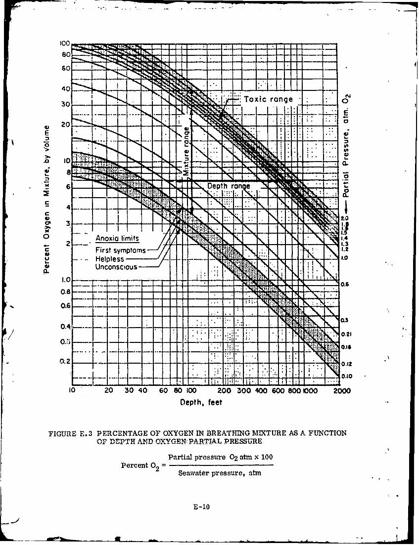
40
o 0 Tnoxic rlimits
ECC
00
6/ 1' J I~ I: I 2
'4)
Percenymto02Seawater prsue a.0
Unconsciou~~a.
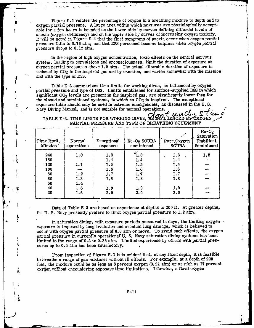
Figure E. 3 relates the percentage of oxygen in a breathing mixture to depth and to Ioxygen partial pressure. A large area within which mixtures are physiologically accept-able for a few hoars is bounded on the lower side by curves defining differenit levels of
anoda (oxygen deficiency) and on the upper side by curves of increasing oxygen toxicity.It -vill be noted in Figure E. 3 that the first symptoms of anoxia occur when oxygen partial IIpressure falls to 0.16 atm, and that DSS personnel become helpless when oxygen partialpressure drops to 0. 12 atm.
In the region of high oxygen concentration, toxic effects on the central nervoussystem, leading to convulsions and unconsciousness, limit the duration of exposure atoxygen partial pressures above 1.2 atm. The actual allowable duration of exposure isreduced by CO2 in the inspired gas and by exertion, and varies somewhat with the missionand with the type of DSS.
Table E-3 summarizes time limits for working dives, as influenced by oxygenpartialpressure and type of DSS. Limits established for surface-supplied DSS in whichsignificant CO 2 levels are present in the inspired gas, are significantly lower than forthe closed and semiclosed systems, in which no C02 is inspired. The exceptionalexposure table should only be used in extreme emergencies, as discussed in the U. S.Navy Diving Manual, and is not suitable for normal operaytons.
TABLE E-3. TIME LIMITS FOR WORKING DIVES, 'ASTNFLUENCED B6XYGEN .PARTIAL PRESSURE AND TYPE OF BREATHING EQUIPMENT
I -, e-02Saturation
Time limit,. Normal Exceptional He-0 2 SCUBA Pure Oxygen Umbilical,Minutes -operations exposure semiclosed S&UBA Semiclosed
240 1.0 1.3 1.3 1.3 1.2180 -- 1.4 1.4 1.4 --
.120 1.1 1.5 1.5 1.5 --
100 -- 1.6 1.6 1.6 --
80 1.2 1.7 1.7 1.7 --
60 1.3 1.8 1.8 18 --50 1.440 1.5 1.9 1.9 1.9 --
30 1.6 2.0 2.0 2.0 --
Data of Table E-3 are based on experience at depths to 200 ft. At greater depths,the U. S. Navy presently prefers to limit oxygen partial pressure to 1.2 atm.
-In saturation diving, with exposure periods measured-in days, the limiting oxygenexposure is imposed by lung irritation and eventual lung damage, which is believed tooccur with oxygen partial pressure of 0.6 atm or more. To avoid such effects, the oxygen-partial pressure in currently operational U. S. Navy saturation diving systems has beenlimited to the range of 0.3 to 0.35 atm. Limited experience by others with partial pres-sures up to 0.5 atm has been satisfactory.
From inspection of Figure E. 3 it Is evident that, at any fixed depth, it is feasibleto breathe a range of gas mixtures without ill effects. For example, at a depth of 200feet, the mixture could be as lean as 3 percent oxygen (0.21 atm) or as rich as 17 percentoxygen without encountering exposure time limitations. Likewise, a fixed oxygen
Ii E-1f
:1
coneentration in the br',athing mixture will support dives to a range of depths. A mixturecon aninq 10 percent ,J.Ign, for example, would permit operations between 36 and 360 4
I'eet, with the po-sibilit-. of short excursions as deep as 600 feet. It is important to againote that anoxia can occur if lean mixtures intended for deep operations are breathe'd dur-
ing ascent and decoi;npression. It is necessary to provide higher oxygen percentag,- atshallower depths to .-ta: within the working range indicated in Figure E. 3.
E. 5. 2 Diluent Gases
The oxygen percentages shown in Figure E. 3 would be appropriate with any dtuentLras or mixture of diluent gases that might be applicable to diving. Oxygen-nitrogen mix-tures, including air, can be used freely if nitrogen partial pressure is limited to 3 .. tn,the pressure at which the first symptoms of nitrogen narcosis appear, and nitrogen partialpressures to 5.5 atm can be used with care by experienced DSS personnel for short periods. ()(This is equivalent to diving at 200 feet with air.) For greater depths, helium is the dilu-ent gas now generally used because it does not produce a narcotic effect at any practicaldiving depth and because its low density reduces breathing effort. The principal disad-vantages of helium are its limited availability and resulting high cost, the effect that ithas on the voice that makes it difficult to communicate, and the high leakage rates exper-ienced in joints and seals. Nitrogen at partial pressures up to 3 atm can be mixed withhelium as a means of conserving helium, improving speech intelligibility, and reduc"':gcost, but precise information on physical and engineering properties of helium-nitrogen -oxygen mixtures is not available at the present time.
Hydrogen has been proposed as a diluent gas for depths beyond 1000 feet becauseof its low cost and because its density is half that of helium. However, the effects ofhydrogen on body tissues at high pressures have not yet been explored. Furthermore,hydrogen-oxygen mixtures are readily ignited by static-electricity discharges unless oxygenconcentrations are below the combustible limit, which is at 6 percent oxygen at 1 atmpressure. (4) Explosive limits of oxygen-hydrogen mixtures have not yet been investi-gated at high pressures.
E. 5.3 Decompression Considerations
Decompression considerations also influence the selection of breathing-gas compo-sition. The length of the decompression period is a function of the partial pressure ofdiluent gas (helium or nitrogen) in the breathing mixture. The decompression period canbe shortened by using oxygen concentrations close to the toxic limit during a scheduled divingperiod and during the decompression period. (2, 3) This approach is most effective fordives at shallow to moderate depths where the proportion of oxygen can he large enoughto si.nifici.ntly reduce the partial pressure of dihucnt gas. Under marngnal conditions,use of a high-oxygen mixture may eliminate the decompression period entirely. Oxygenis not normally a limiting factor in decompression because it -is metabolized rather thantaken into simple solution.
E. 5.4 CO Levels
Although experimental data relating CO concentrations to toxic effects in helium-oxygen mixtures are not now available, effects can be predicted with reasonable assurancebased upon CO-O 2. ratios. Accordingly, it is recommended that, for the present, COlimits for routine working exposure be based-upon a constant CO-0 2 ratio equivalent :o Ippm CO for each percent of oxygen in the breathing gas. On this basis, the limit for air
containing 21 percent or,.Vren would be 21 ppm CO, and the limit for a breathing gas con-taining 2 percent oxygen would be 2 ppm CO.
E-12
U -_J- -~
I
It should be mentioned that far higher concentrations than those mentioned abovecan be tolerated in emergencies with levels of discomfort. For example, in air at atmos-ph-:'ic pressure, exposure to a level of 150 to 250 ppm CO for many hours will cause asevere headache, and a level of 1600 ppm CO will cause confusion and collapse within Ihctr. Using the CO-O2 criteria above, when working in a saturation-diving environmentcontaining only 2 percent oxygen, a headache should occur with a CO level of 15 ppm, andconfusion and collapse should be expected with a CO level of 160 ppm. The time beforecollapse should be reduced in-inverse proportion with CO and 02_ partial pressures. (5)
Analyses of breathing gases in SEALAB indicated levels of about 0, 3 ppm CO inoxy 'ren manifolds and about 0. 6 ppm CO in He manifolds and mixed-gas lines (1.) Thoselevels would be well within the recommended limit of 3 ppm CO for an atmosphere con-taining 3 percent oxygen. However, additional CO can enter the system from diver metabo-lism, and activities such as smoking (not normally authorized in U. S. Navy DSS) or cooking.Thus, CO concentration in a habitat would nornially be expected to increase with time. COcan be converted to C02 with catalytic burners and removed by the C02 absorber. It canalso be diluted to acceptable concentrations by periodic ventilation of the living space. Cur-rent DDS life-support systems provide Baralyme and activated-carbon canisters to absorbC02 and odor, but these do not reduce CO levels. Future DSS may provide means for COremoval. Without a CO removal system it may be necessary to occasionally ventilate aDSS to dilute CO to acceptable concentration.
E. 5.5 C02 Levels
Figure E. 4 shows C02 tolerance zones as a function of percentage C02 and depth,at partial pressures taken from Figure E. 2 for a 1-hour exposure period. As with oxygen,the physiological effects of carbon dioxide depend upon its partial pressure in the bloodand therefore in the breathing gas. The percentage of carbon dioxide in the breathinggas that can be-tolerated at diving depths decreases with depth, and the respiratory volumerequired to ventilate the lungs at depth remains approximately equal to that at sea level.
If a DSS breathing circuit includes volumes from which exhaled air is rebreathed,these volumes must be ventilated to dilute the carbon dioxide to a nontoxic level. If all ofthe carbon dioxide produced is mixed with all of the ventilating gas, the reduction of partialpressure depends only upon the ratio of carbon dioxide-production rate to dilution-gas flowrate. This ratio must be about 1:100 to limit carbon dicxide to 0.01 atm partial pressure,or 1:50 for 0.02 atm pp C02.
The quantity of ventilation gas can be reduced if the concentration of carbon dioxidecan be reduced by other means such as absorption by a carbon dioxide absorbent. Thus,D-SS-might employ canisters of absorbent through which breathing gas is circulated to rc-duce the carbon dioxide level, thus reducing the quantity of ventilation gas required.
Unventilated dead space has a significant effect on the respiratory volume requiredfor control of carbon dioxide. Examples of unventilated dead space are the natural volumeof the mouth and throat, the volume of a mouthpiece between non-return valves, and thevolume of an open full face mask. The effect of dead space is to physiologically increasethe volume of inhalation by the amount of the volume of the dead space. Thus, if normaltidal volune is 1 liter and the dead space in a full face mask of 1/2 liter is added, the in-halation volume needed to maintain a normal carbon dioxide level in the blood increasesto 1. 5 liters. The effort of breathing the extra volume reduces the maximum productivework level and increases the quantiny of breathing gas neededlby 30 percent. If - -- aation volume of 1. 0 liter is maintained, only 0. 5 liter of fresh gas would be obtained with(,-,.h inhalation, and this would doublc the respiratory frequency aid gas consumption. It- ways desirable to minimize do:ad space in any diving equipment to the extent possible-Mlo neeting other rcquirmrnts.
E-13,TI f
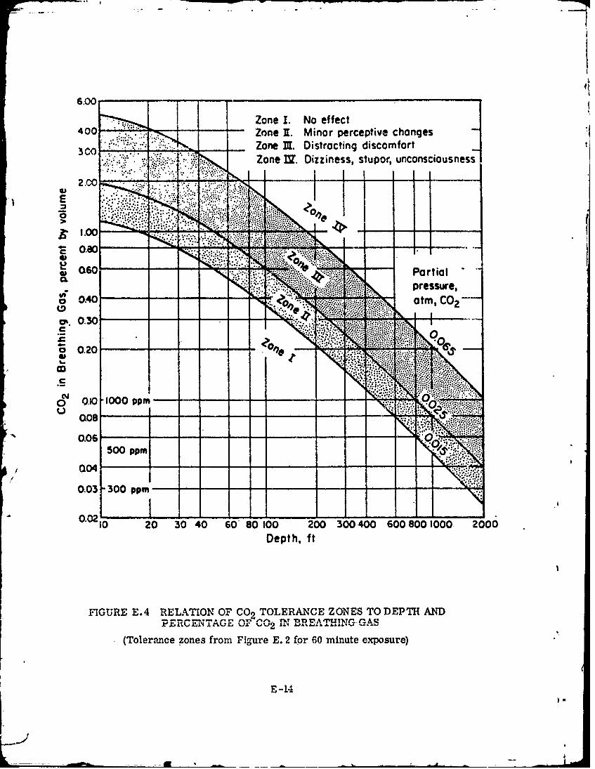
4?
6.0040Zone I. No effectI
-Zone 1. Minor perceptive changes 1Zone MI. Distracting discomfort1Zone U7. Dizziness, stupor, unconsciousness
E i
1.0
CL
00
00.0 3000 ppm-- - -- ___
0U20 2 04 08 O 0 040608000 20
0041
REFERENCES
(1) F. W. Williams, U. S. Naval Research Laboratory, "Source of Contamihantsin Diving Systems," Research Report No. 6-70, Proceedings: Purity Standardsfor Divers' Breathing Gas Symposium, July 8-9, 1970.
(2) U. S. Navy Diving Manual, NAVSHIPS 0994-001-9010
(3) C. J. Lambertsen, "Limitations and Breakthroughs in Manned Undersea Activity,"Supplementary Transactions of 2nd Annual MTS Conference# June 27-29, 1966,Marine Technology Society, 1030 15th Street, N. W., Washington D.C. 20005.
(4) B. Lewis and G. von Elbe, Combustion, Flames, and Explosion of Gases, AcademicPress, Inc., 1951.
(5) J. D. Bloom, M. C., USN, "Some Considerations in Establishing Divers BreathingGas Purity Standards for Carbon Monoxide," Research Report No. 6-70, Proceed-ings: Purity Standards for Divers' Breathing Gas Symposium, July 8-9, 1970.
b
I
I
i
E-15/(E-16 blank)
_ )

APPENDIX F
GENERAL GUIDELINES FOR ATMOSPHERIC EVALUATION OF MANNED DSS
F. 1 INTRODUCTION
It is imperative that a DSS provide an acceptable atmosphere for its operators/occupants. To assure such an atmosphere, it is necessary to check the makeup of theatmosphere under operating conditions. This includes the search for contaminants whichmay enter the DSS by way of materials of construction, as cumulative contaminants fromcompressed gases and from other sources such as solvents used to clean the system. Theamounts of coi. 'minants found must be considered and evaluated in terms of personnelsafety. This evaluation should take into account the particular contaminants and tbeirtoxic and corrosive hazard potentials as well as their source and potential methods oftheir removal. Whether or not the DSS is hyperbaric, the length and type of its plannedmissions must be considered.
There are three basic requirements for the evaluation of closed atmosphericsystems: a valid sampling program, effective analysis techniques, and meaningful inter-pretation of the data obtained. The approaches to be used to satisfy these requirementswilldepend somewhat on-the atmosphere under consideration; that is, whether the systemis to be operated at normal or high pressure. what gas mixture will be used, the expected
S duration of the-dive (or "closed" test) and the type of atmosphere control equipment em-ployed. The atmosphere evaluation should encompass both the "livable" volume and the
compressed gas supply.
A DSS which will operate normally at one atmosphere should be subjected to twoevaluation trials. The first should be an unmanned trial to ascertain the habitability ofthe DSS primarily in terms of trace contaminant buildup. The second should-be a mannedmission intended to ascertain the effectiveness of the atmosphere control equipment. ForDSS that operate at pressures higher than one atmosphere, an unmanned run at the maxi-mum expected operating pressure, for the purpose of evaluating the life support systemunder actual operating- conditions is also necessary. Proof of the performance of the car-bon dioxide removal equipment at the lowest operating temperature and maximum operatingpressure is of particular importance.
F. 2 SAMPLING APPARATUS AND PROCEDURES
There are two sorts of sampling which are needed for complete evaluation. Thefirst is on-site sampling and analyses for atmospheric contaminants which may not be
t. stable; the second-is sampling for laboratory evaluation. Durin, sampling, f any unusual
odors are detected, their origin-should-be ascertained and corrected if necessary. 01-factory detection of some compounds such as hydrogen sulfide and ammonia is much-moresensitive than chemical means.
When possible, it is advantageous to obtain atmosphere samples at higher thanambient pressure to facilitate later analysis.
The recommended procedure for obtaining an atmosphere sample, using stainlesssteel bottles and a suitable compressor, is as follows:
F-I
1"-
a. The stainless steel bottles should be evaluated for cleanliness before usingthem for sampling. * 4
b. Open valve to previously evacuated steel bottle and allow to come to atmos-pheric pressure inside the submersible being evaluated.
c. Thread flask into tee o- nipple as provided at the pressure gauge connection
on the pu-np.
J. Pump flask to between 50 to 60 psig.
e. Release pressure. Repeat pumping procedure three times. Do not releasepressure final time.
f. , Close valve to flask.
g. Turn off compressor.
Samples from high pressure gas systems can be obtained by making suitable con-nections. Provision should be made so that the connecting piping between the pressurizedsystem and sampling bottle can be well purged to allow collection of a valid sample. Allpressurized gas systems and gas supplies to be used with the sealed DSS should be sampledand-analysed, including any such gas supplies which could accidentally be vc'ited inboard.
Samples from pressurized capsules or storage flasks can be obtained directly with-out the use of the pump. Extreme caution should be exercised to assure that the bottle isnot filled beyond its rated pressure.
In the event that there is no power available to run the compressor, the valves onevacuated sample bottles located inside the DSS can be simply opened and then reclosedto c6llect a sample at the internal pressure of the DSS. In such a situation, each bottleshould be equipped with an absolute pressure gauge with which to note the bottle pressuresbefore the valve Is opened and after the bottle pressure has equalized. The gauges alsoserve to ascertain that sample bottles remain fully evacuated-until just prior to use, there-by assuring a valid atmosphere sample from the DSS.
F. 3 ANALYTICAL PROCEDURES
The second major phase in atmosphere evaluation is the selection of appropriatetechniques for analysis. The techniques and instruments which can be used will vary withthe type of closed system being evaluated, the operating conditions expected, and the par-ticular gases and contaminants suspected or of interest, Some suggestions which may beapplied to specific contaminants or groups of contaminants are presented. Further detailsappear in other sections of this appendix.
• It is important that the sample bottles do not retain a memory of previous
usaces. The cleanliness-of each bottle can be determined as follows: Pressurize
the sample bottle with dry oil-free nitrogen and allow it-to come to thermal
equilibrium (2-4 hours depending on temperature). The nitrogen contained in the
sample bottle can then be analyzed by appropriate procedures given-later in thisappendi;g.
F-2
a., Total Hydrocarbon Analysis
2',j,,sider first the bottled samples from either manned or unmanned tests.The detection and determination of specific contaminants is a difficult and time-consumingtask. Tt is su-,rested that a total hydrocarbon analysis of the sample be obtained using aras chroiliatographic system equipped with a back-flush valve, such as is the NRL TotalHydrocarbon Analyzer. The THA is, basically, a gas chromatograph equipped with aflame ioni::ation detector. In normal operation of a gas chromatograph, a sample is in-tro,!uced into a-partitioning column and is swept through the column by means of a carrier
. ihelium, nitrogen c -iir) to the detector. The THA differs from the normal gaschromatograph in that it, additionally, has a "back-flush" capability. Back-flushing isreversal of the flow of the carrier gas at a selected time after the sample has been intro-duced into the column. Instead of allowing the components to separate in the partitioningcolumn into individual components which are then passed into the detector, back-flushingthe column regroups the sample into one peak, which then is eluted from the column intothe detector. Most commercial gas chromatographs equipped with a flame detector canbe modified to perform the same analysis.
In the event that the total hydrocarbon value, excluding methane, based on a n-hexanestandard or equivalent, exceeds 15 mg/m 3 , the total hydrocarbon mixture should be analyzedfurther for specific contaminants, providing analytical information as to the presence of spe-cific compounds (such as benzene) which might be present in unacceptable concentrations.The total hydrocarbon value of 15 mg/m 3 , per se, should not disallow the acceptance of theatmosphere under evaluation. Detailed analyses can be done by normal elution gas chroma-tography, mass spectrometry, infrared analysis or a combination of these techniques.
b. Chlorinated Hydrocarbons
One specific class of compounds that is included as part of the "total hydro-carbons" is the-halogenated hydrocarbons (halocarbons). The halocarbons generally en-countered, in almost all cases contain chlorine and can be called "chlorocarbons." Thesecompounds are of special interest because of their high degree of toxicity as comparedto hydrocarbons and the corrosiveness of their degradation products.
The total chlorocar on content of the atmosphere should be determined and, iffound tp be in excess of 15 mg/mv, a sample should be further analyzed for specific con-tami.nants. An instrument capable of measuring total chlorocarbons at this level is theDohrmann Microcoulometer. Trichloroethylene is a compound that merits special con-sideration and should be looked for specifically in atmospheres from all closed environ-mental systems that use a caustic for CO 2 removal. The significance of this compoundis discussed later in more-detail.
Often, atmospheres are found to be contaminated with refrigerants or chlori-nated cleaning solvents such as Fr- on-ll3. The NRL Total Hydrocarbon Analyzer is capableof detecting many of the very volatile refrigerants and solvents at the same time that a totalhydrocarbon analysis is being carried out and is also cir,,',bl of detecting some of the less
, volatilo solvents by its use in a different mode. Obviously, U" chlorinated contaminants arefound to be present at levels in excess of 15 mg/m 3 , it Is useless to run a total chlorocar-bon analysis. The sample should-then be analyzed directly for individual chlorocarbons.This can be done through use of a gas chromatograph equipped with an electron capture de-tector o a h1ilerocoulorniat C dUIrtcrcbe.-th a sm table concentrating technique.
F-3
1

c. Carbon Dioxide
The carbon dioxide CO2 concentration in the atmosphere during a mannedevaluation should be followed closely by an on board monitor during the dive and verifiedas soon as possible by gas samples obtained in steel bottles during the dive. The C02level can be determined by several means such as gas chromatography, nondispersiveinfrared analysis or an equivalent method. If gas chromatography is used, the preferreddetection method, except at very low concentrations, is thermal conductivity.
d. Reactive Contaminants
Some potential contaminants are too reactive or absorptive to allow quantita-tive sampling by the pressurized bottle technique. Such compounds must be analyzed inthe DSS during closed tests. Reactive contaminants include ozone, sulfur dioxide, hydro-gen sulfide, phosgene and nitrogen dioxide. Detector tvbes should be suitable for the analy-sis of these compounds.
e. Carbon Monoxide
A trace contaminant of interest because of its toxicity and ubiquity is carbonmonoxide. It should be monitored during any manned test by means of detector tubes. Thiscontaminant can also be analyzed in the bottle samples. Gas chromatographic techniquesare available which are based on either the electrical breakdown (Karmen) detector or con-irersion to methane-and detection by flmne ionization.
f. Mercury Vapor
Mercury-vapor can be detected by means of detector tubes.
g. Aerosols
If, at the termination of the unmanned test or during the manmed evaluation,any aerosol such as a mist, smoke or fog is seen, a sampling program should be under-taken to ascertain that it presents no hazard to inhabitants.
F. 4 ATMOSPHERE EVALUATION PROCEDURES
The evaluation procedures to be used during the various trials must be based onthe type of DSS and the type and duration of closed atmosphere operations planned. Analy-sis for an:ozpheric contaminants in the unmanned enclosures should be made before man-ned evalu -:.ons are conducted. Samples of the gas supplies to be used should be collectedfor analysis in order to establish the baseline level of contaminants.
a. DSS Designed to be Operated at One Atmosphere
(1) Unmanned Evaluation
Bottled gas samples for the unmanned evaluation should be taken at thebegnnin -nndat the termination-of a "closed hatch" test. The duration of the test shoulddepend or. the-len, l of time the DSS will be closed during an actual dive. With the-shortmissicn DSS, the test should be twice as long as the actual dive time. That is, for an aver-age div time of 8 hours the closed hatch test should last for 16 hours. In situations where
F-4
a .- ~'---
the expected mission time will be much longer, the closed hatch test should run-at least16 hours or longer. The test duration should be dictated by the type of DSS and its expecteduses. As much of the equipment as possible within the DSS should be operating during thetest. In DSS equipped with a charcoal (carbon) filter the charcoal should be removed priorto the unmanned test, thus simulating the most severe condition.
Analyses of the gas samples should be made by the methods describedin paragraphs F. 3a, -b, -c, and -e. Tests for mercury should be conducted in the DSS atthe end of the closed test. Upon opening the DSS following the closed test, visual observa-tion for aerosols should be made and note made of any odors which may be meaningful inthe final evaluation of the system.
(2) Manned Evaluation
c o lDuring a manned trial all systems should be in operation including thecarbon filter system. This trial should last sufficiently long to evaluate the atmospherecontrol equipment. A bottled sample of the atmosphere should be taken at the beginningo.f the dive just after the hatch is closed and a final sample taken at the termination of thedive just prior to opening the hatch. These bottled samples should be analyzed for all con-taminants listed in the unmanned evaluation previously described.
The carbon dioxide buildup during the manned trial should be monitoredby means of instrumentation contained within the DSS and the data verified by laboratoryanalysis of the bottled samples. Detector tubes should be used during the dive to followthe carbon monoxide level. Detector tubes should also be used approximately halfwaythrough and at the end of the dive to determine the presence of reactive gases like ozone,ammonia, sulfur dioxide, hydrogen sulfide, phosgene and nitrogen dioxide (so-called"nitrous gases"). If a suspicious odor or irritation of eye or mucous membranes is ob-served, tests for reactive gases should be made immediately. Tests for mercury shouldalso be made during this trial. Note should be made of aerosols detected and appropriateaction taken.
b. DSS Designed to be Operated at Hyperbaric Pressures
In hyperbaric systems, atmosphere sampling should be done both at a pres-sure near one atmosphe,'e and at the actual pressure at which the-system is to be used.
The procedures used should be patterned after those described under "DSSDesigned to be Operated at One Atmosphere." The low pressure evaluations can be madeat one-atmosphere, if feasible, or at the lowest practicable sea pressure equivalent. Tracecontaminants can be detected and identified more readily in the low pressure samples beforethe atmosphere has been diluted with high pressure gas. Identification of contaminantsfound in the low pressure sample could be useful both in determination of their sources andin assessing their seriousness. A sample of the gas used to pressurize the system shouldbe obtained and analyzed to ensure that contaminants found actually arose from the chamberitself and were not introduced with the pressurization gas.
The high pressure gas systems associated with hyperbaric DSS should alsobe checked for contaminants as these systems could be a major source of contaminants inthe chamber during actual use. This is especially true of 02 systems in which the gas Isconsumed by the men and is added constantly to maintain the correct partial pressure. Con-tamin-nnts in this gas would thus build up in the chamber over a period of time.
F-5
I iIn view of the scarcity of information, at the present time, about the efficiency of 41
C02 absorbents at high pressures and low temperatures, it is recommended that the C02 re-moval system in a hyperbaric DSS be evaluated in the unmanned chamber at v'orking pressure,d temperature. This would be especially important in chambers operated at low tempera-tures. Such an evaluation could be carried out by adding C02 to the system at a constant ratecorrecnonding to its expected rate of production based upon the number of men in the chamberand by monitoring the CO2 levels in the chamber by extenal measurements.
Atn.ospheric analyses should then be made on the manned chamber at one at-mosphere pressure with all systems operational, as outlined in the preceding section.
F. 5 ADDITIONAL DISCUSSION ABOUT CHLOROCARBONS
If human occupancy is planned, halogenated solvents, as a class, should be avoided inthe selection of materials for the construction and maintenance of any closed atmosphericsystem. These remarks are particularly directed at cblorocarbons which have become widelyused in the past few decades. Their hazard potential is of an insidious nature. This resultsfrom the fact that although the toxicity or corrosiveness of the parent compounld may be rel-atively low, the products of their chemical reaction or thermal degradation are often toxic orcorrosive.
Trichloroethylene is an example of a chemical compound whose reaction product ispotentially hazardous. When passed through a bed of moderately heated alkali, a dehydro-chlorination reaction occurs which yields dichloroacetylene.
Dichloracetylene is an extremely toxic compound which- must be excluded from closedatmospheres. Unfortunately, no analytical method is available for the direct analysis ofdichloroacetylene in a complex atmospheric mixture at the required low levels of one ppmor less. Consequently, the precursor compound, tricbloroethylene, must be kept at verylow levels. Trichloroethylene can be detected at low concentrations in air. Because It isso insidious, trichloroethylene should not be used in closed atmospheric -systems for anypurpose.
The presence of carbon monoxide (CO) removal equipment in a DSS, more specifi-cally a CO/H 2 burner, complicates the significance of the presence of halogenated hydro-carbons. Halocarbon compounds decompose in the CO/H 2 burner to form breakdjown pro-ducts which are detrimental to both man and materials. Thus the maximum allowable limitof a contaminant must be based not only upon its own toxicity, but also upon the tcxicityof its breakdown products and the effects of the acidic products on equipment and machinery.
F. 6 INTERPRETATION AND APPLICATION OF DATA
Sampling and analysis of atmospheric gases must be followed by a meaningful inter-pretation of data. After the identities and concentration levels of contaminants are estab-lished, evaluation of potential toxicity hazards must be made based on such guidelines asindicated in Appendix E, and publications of the Bureau of Medicine and Surgery and the NavyToxicology Unit. Based on these considerations, concentration limits can be establishedfor trace contaminants both as groups, such as total hydrocarbons, and specific compounds.
The effects of various contaminants should be-interpreted in the light of the type ofDSS involved, considering factors such as time and the effect of pressure. For example,the concentration value of 15 mg/ms for either total hydrocarbon or total chlorocarbon isa signal for invokirg detailed analyses for individual compounds. Finding totals for these
F-6.- /
U -
types of compounds in excess of 15 mg/m 3 , however, should not automatically cause rejec-tion of the system being evaluated. Maximum limits, whether for individual compounds orfor classes of compounds, could be different for each system being evaluated and thus shouldbe established to be in accordance with the requirements for and demands of the particulars.z-em. Therefore, the types of atmospheric data taken, the conditions under which theyare obtained and the interpretations which are made, should be fitted to the particular DSSunder consideration. For example, the maximum acceptable limit for carbon monoxide innuclear submarines,- which operate at a pressure of one atmosphere, has been set at 25 ppmf)r continuous exposure-of 90 days. Since the toxic effect of carbon monoxide is a function ofit. partial p- ssure, the concentration in ppm which is acceptable will decrease as the totalpressure incLf-ases. Other factors to consider are length of exposure, presence of specificpu ification equipi, ent, and type of mission expected.
'Advice on toxicity considerations not covered in available publications may be ob-
tained from the Navy Toxicology Unit, Naval Medical Center, Bethesda, Maryland.
L
Fbl
I
/
I
4{
£ F-7/(F-8 blank)
*
APPENDIX G
GENERAL GUIDELINES FOR CLEANING BREATHING GAS SYSTEMS
G. 1 INTRODUCTION
This Appendix pcovides general guidelines for developing cleaning procedures andcriterfa for breathing gas systems and have been specifically developed for breathing sys- I-tems u;ed in conjunction with all Navy man-rated Deep Submergence Systems. Examplesof breathing gas systems in this category .re metabolic om'gen, air, and HeO2 .
These general guidelines conv(y the lates; -erience gained by those knowledgeablein cleaning breathing tgas systems. It is not inten..J to restrict the development or use ofnew ideas, procedures, hardware or equipment.
G. 2 - REFERENCES
S G. 2.1 Military Standards
MIL-STD-1246A - Production C, leanliness Levels and Contamination Control Program.
MIL-STD-767A - Cleaning Requirements for Special Purpose Equipment Including
Piping Systems.
MIL-STD-1330 - Cleaning and Testing of Oxygen and Nitrogen Piping Systems.
G. 2.2 Military Specifications
* MIL-D-16791E - Detergents, General Purpose (Liquid NONIONIC).
G. 2.3 NASA Specifications
MSC-SPEC-C-6B - Spacecraft Chemical %nd Cleanliness Requirements.
MSFC-SPEC-164A - Cleanliness of Components for use in oxygen, fuel andpneumatic systems.
KSC-I23(D)O - Cleanliness Levels, Cleaning Protection and Inspection Proceduresfbr parts, field parts, assemblies, subsystems and systems for pneumatic-use in supportequipment.
G. 2.4 -Other
BUSHIPS INSTRUCTION 9230.12A - Cleaning Procedures - Oxygen and NitrogenSystems.
MARE ISLAND Process Instruction 05 6-839.
SPBNSY Test No. 516T -2122 E - ASR diving system piping systems cleaning* testing and certification.
. aINRL Mermorandum Report 2122 Guidelines for Atmosphere Evaluation of MannedS ! Sall Submersibles and Chambers.
I. -
G. 3 DEFINIT*ONS
G.3. 1 Cleanliness Level
An established level of maximum allowabie contamination based on size, distribu-tion or quality in a given area or volume.
G. 3. 2 Contamination
Any foreign material.
G.3.3 Fiber
Particle having a length to width ratio of 10 to 1 or greater.
G. 3.4 Micron
A unit of measure equal to one-millionth of a meter or thirty-nine millionths of aninch (0. 000039 inch); e.g., 25 microns is approximately 0.001 inch.
G. 3. 5 Non-Volatile Residue (NVR)
Soluble material remaining after evaporation of a volatile liquid or determined byspecial purpose analytical instruments usually measured in milligrams per unit volume.
G. 3. 6 Particle Size
Particle size is expressed as the apparent maximum linear dimension or diameter
of the particle.
G. 3. 7 Significant Surface
Any surface of an item or product which is wetted by the breathing gas and there-fore is required to. meet the established cleanliness level requirements.
G. 4 GENERAL PROCEDURES
G. 4. 1 Remarks
There are two recognized procedures used to date for cleaning breathing gas systems.
a. The system is cleaned in individual elements prior to assembly and thenassembled under controlled conditions.
b. The system is cleaned following assembly, usually by flushing.
Approach a.
If approach 'a' is used, careful records should be kept relating the total system tothe indilrdual components- cleaned. This is to insure that each item in the system has beenproperly cleaned. The end result should be a simple system schematic drawing identifyingeach-element of the finshed assembled system and how cleanliness was achieved.
G-2
it.
Approach b.
If approach 'b' is used, a record should be kept indicating where the cleaningagent was introduced and taken out, any jumpers used, the valve lineup during flush andthe direction of flow. In addition, if flushing blocks are used, the removed valve inter-nals should be cleaned in accordance with approach 'a'.
G. 4. 2 Sequence (Suggested)
Whether 4. 1. 1 or 4. 1.2 or a variation of both is considered, the following generalsteps should be taken:
a. Specified valves and components should be removed from the system andcleaned and tested separately where applicable.
1b. Piping systems, minus specified valves and components, should be back
flushed for particulate matter removal.
c. 1 Piping systems should be hydrostatically tested to 1 1/2 times their workingpressure.
S( d. Piping systems should be cleaned for hydrocarbons.
e. Piping systems should be flushed with dry oil free nitrogen until it is estab-lished that the gas is contamination free.
f. Piping systems should be assembled complete with all valves and componentsand tested for tightness to their working pressure.
g. An atmospheric analysis should be performed to insure all toxic materialshave been removed.
r G. 5 CLEANING METHODS AND MATERIALS
G. 5.1 General Remarks
The following comments are derived from-experience gained in cleaning breathinggas systems. As noted in 1. 3, it is not the intent of this section to restrict cleaning pro-cedures, materials and agents to those mentioned below, but provide information-based onexperience. The agents below are those which have been primarily used in the past toclean breathing gas systems. For additional information on various cleaning agents MIL-STD-1246A is suggested.
1*-It is important to note that a system should be flushed for particulate matter before
strength testing is accomplished. Experience has shown that particulate matter can bedriven into cracks, crevices, and software if particulate matter is not removed.
G-3
G. 5. 2 Trisodium Phosphate
It is suggested that BUSHIPINST 9230.12A2 be used as general guidelines for gener-ati.n cleaning procedures in conjunction with this agent.
The cleaning agent, Trisodium Phosphate, is considered to be the most acceptableagent for total system flush (4.1 approach (b)), primarily due to the fact that it has no po-tential for producing toxic materials if inadvertently left in-the system.
The procedure as outlined in BUSHIPINST 9230.12A is somewhat complex.
Care should be taken to insure that all of the cleaning agent has been removed fromthe system. If the cleaning agent is not completely removed, particulate matter may resultpossibly creating problems with precision components in the system.
Problems have also occurred with "Parkerized" components (bottles) after usingwater base detergents including Trisodium Phosphate. If the component is not completelydried immediately after flushing, rusting will occur thus creating particulate matter. Itis recommended that a water based cleaning agent not be used in conjunction with theseitems (bottles).
G. 5.3 Trichlorotrifluoroethane
It is suggested that MIL-STD-1330 be used as general guidelines for generatingcleaning procedures in conjunction with this agent.
Difficulties have been encountered in removing this agent from piping systems,especially from dead end piping and flasks. This has been true for both the cleaning andpurging operation since this agent is a liquid at normal temperatures with a boiling pointof 117. 6 F at one atmosphere.
The agent itself is not a very toxic material at atmospheric pressures, nor does ithave a deleterious effect on metal systems. This agent, however, in the presence of aCO/H 2 burner does break down into hydrogen chloride (HCL) and hydrogen fluoride (HF) gas.
The production of these two components would give rise to both a toxic and corro-sive problem in the concentration range of one ppm W volume.
Another difficulty encountered is incompatibility with synthetic materials such asNylon, Tygon, rubber, plastic and other materials that may be use(! in typical breathinggas systems. In view of the above discussion, the following precautions should be taken:
a. All non-metallic components should be checked for compatibility with thisagent and removed where applicable.
b. Care should be taken to insure that all the agent is removed after cleaningespecially in systems which include a CO/H 2 burner.
c. This agent should not be used in conjunction with systems with a large numberof pockets (low points in the systern) where cleaning -,, .. ts might collect.
Requests for copies of this document should be sent to:
Commarding Officera~:l "Publcation and Forms Center
5501 Tabor AvenuePhiladelphia, Penn. 19120
G-4
d. Once cleaning has been accomplished, the system/component should beflushed (and baked where practical) several times to insure that all of the cleaning agenthas been removed.
e. A gas sample should be taken from the completed system to assure thatall of the cleaning agent has been removed. The system should be undisturbed for 24 hoursbefore this sample is taken. Acceptable limits for trichlorotrifluoroethane should be5 ppm by volume.
G. 5.4 Trichloroethylene
This agent must not be used in conjunction with breathing gas systems because ofthe potential hazard it presents. When passed through a bed of moderately heated alkali(CO2 removal chemicals) a dehydrochlorination reaction occurs which yields dichloro-acetylene.
Dichloroacetylene is an extremely toxic compound which must be excluded fromclosed atmospheres. Unfortunately, no analytical method is available for the direct analy-sis of dichloroacetylene in a complex atmospheric mixture at the required low levels of1 ppm or less. Consequently, the precursor compound trichloroethylene must be keptat very low levels.
If under dire circumstances it is considered absolutely necessary to use this agent,or if it has been found that a component-has been inadvertently cleaned with this agent, thefollowing steps should be taken:
a. After cleaning has been accomplished, the system/component should bepurged (and baked where practical) several times.
b. A gas sample should be taken to insure that all of the cleaning agent hasbeen removed. The system should be undisturbed for 24 hours before the sample is taken.Acceptable limits for trichloroethylene should be 1 ppm by volume.
G. 5.5 Non-Ionic Detergent
It should be noted that this discussion is limited to MIL-D-16797 Type I (water' soluble) agents. Non-ionic detergents are primarily used to decrease the surface tension
of the-mixture. This improves wetting of the surface (e.g., allows the cleaning agent tomove easily and penetrate into small cracks).
When using this agent the following precautions should be taken:
a. The specific agent should be checked to insure that it produces no toxico-logical problems.
b. The specific agent and its concentration should be checked with respect tothe cleaning temperature. Concentrations should range below 1%. Problems have occurredat high concentrations and temperatures. Some of these agents have precipitated out caus-ing a gel to form on the internal portion of the system.
G. 5.6 Uitrasonie Clearng
The item to be cleaned should be immersed in a suitable bath of-cleaning solutionthat Is energized by an appropriate ultrasonic device. The cleaning solvent or solution
G-5
and the frequency of the ultrasonic energy should be carefully selected to be compatibleand e.,ffective. This method should not be used on items which may be degraded by sonicenerg- unless precaucions are taken that are demonstrated to provide effective protection,For typical breathing gas system components, it is recommended that 10 watts/m92 beapplied for 3-5 minutes.
G. 6 SAMPLING AND ANALYZING
G. 6. 1 Geiteral Remarks
As noted in G. 1 any proposed techniques for both sampling and analyzing will beacceptable provided it -.an be established by sound engineering principles that the result-ing system is cleaned to the necessary tolerances. The following procedures which re-late system size to cleanliness have been successfully applied by the aerospace industry.
fG. 6.2 Sampling Techniques
G. 6.2.1 Small Components
A 500 ml (minimum) test solution is used to determine the particle populationand the nonvolatile residue on significant surfaces of small components (less than 1.0square foot in surface area).
a. Divide the 500 ml test solution into quantities in proportion to the surfaceaiea of the individual components used to make up 1. 0 square foot of surface area.
b. Flush each component with proportionate share of test solution.
c. Collect the flushing solvent for the analysis of the sample as applicable.
d. Thoroughly dry components after completion of flushing operation.
G. 6. 2..2 Components 1.0 Square Foot in Surface Area
A 500 ml test solution used to determine the particle population and the non-volatile residue on the surfaces of the components having significant surface areas from 1.0square foot through 5.0 square feet should be prepared by flushing the test solvent over thesignificant surfaces and collecting the solvent for the analysis. The component should bethoroughly dried after completion of flushing operations.
G. 6.2.3 Components with Surface Areas Greater than 5. 0 Square Feet
test solution to determine the particle population and nonvolatile residue onthe significant surfaces of components having significant surface areas greater than 5.0square feet should be prepared as follows:
a. Flush the significant surfaces with 100 ml (maximum) of test solvent per
square foot of surface area.
b. Collect the flushing solvent.
c. If more than 500 ml of test solvent is used, the fiushings should be thor-oughly agitated and a 500 ml sample be taken from the total quantity of flushing solution.
d. The component should be thoroughly dried after flushing operation(step (a)).
G-6
a -
G,6.3 Anal-..'tical Techniques
G.6.43.1 Part culate Sample Analysis:
a., Filterirg Procedure:
(14 Using forceps, remove Millipore disc from container, rinse grid-marked surface with filtered petroleum ether and place grid-marked side up on PyrexFilter Holder flase.
(2) Lock funnel to base with spring clamp.
(3) Pour entire contents of sample bottle into funnel.
to(4) Rinse sample bottle with Millipore filtered solvent and add contentsto funinbl.
(5) Apply vacuum to filter flask. When filtration is approximately onehalf complete, release vacuum.
(6) While some liquid still remains in funnel, use Millipore filtered( solvent to carefully rinse funnel walls.
(7) Apply vacuum and pull remainder of fluid through Millipore filterdisc. Do not subsequently rinse funnel walls or filter surface (to avoid disturbing theeven distribution of particles on filter surface). Release vacuum.
(8) Open filter holder. Using forceps, immediately place Millipore filter
in clean Plastic Disposable Petri Dish identified with sample number.
b. Counting Procedure:
(1) Install a measuring eyepiece disc in the eyepiece assembly of themicroscope (either lens if a binocular microscope). Place a stage micrometer on themicroscope stage.
I
(2) Adjust the microscope lluminator intensity and position for maximumdefinition of the stage micrometer scale-as viewed through the microscope.
(3) Calibrate the measuring eyepiece for each magnification to be used.Post chart near microscope for all future work.
(4) With forceps, gently float Millipore filter on film of immersion oilin cover of Plastic Petri Dish. Draw filter over rim of cover to remove excess oil frombottom of filter.
(5) Place Millipore filter on 2 x 3 glass slide on microscope stage (lightlygreasing the slide is desirable in reflected light work to hold filter flat and in place).
* (6) Move microscope stage so that particles on Millipore appear to passunder the n .easu .ng y.i.c.. Count the number f particles in designated size rangeson the entire filter pad. Particles should always be sized by their longest dimensions.Fibers (particles wi.th a ratio of length to width greater than 10:1) should-be listed separately.
G-7
(7) It is always a good practice to prepare a blank analysis, proceedingthrc. .h all fil.rerinr and counting operations without introducing any sample, to determinethe ":)aczroun.t" coumt. This is an excellent measure of cleanliness of glassware solventand ,oc'hniue. Blank counts should not exceed 10"-. of control limits established for theflui,,> urder test.
c. Record results.
G. 6. 3. 2 Nonvolatile Residue
G. 6. 3. 2. 1 Analysis by Gravitational Means
The filtered sample (500 ml nominal volume) should be analyzed for nonvolatile Iresidue content to determine acceptability as follows:
a. . Transfer 500 ml of the solvent into a clean degreased 800 ml beaker. (b. Evaporate the solvent to 10 to 20 ml volume in a steam bath.
c. Transfer the solvent to a constant-weight (within 0.3 mg) tared 30 ml weigh-ing bottle, weighted to the nearest 0. 1 mg.
d. Continue evaporation to a volume of 5 plus or minus 0.5 ml. Do not let Ithe solvent evaporate to dryness.
e. Place the weighing bottle in a constant temperature oven at 221 to 230 degrees Ffor 1. 5 hours. I
f. Cool weighing bottle in a desiccator and then weigh to the nearest 0. 1 mg.
g. Return the weighing bottle to the constant temperature oven for one-halfhour,
h. Repeat f. If the difference between the weights is greater than 0. 3 mg, re-peat step g. until the difference behveen successive weighing is 0.3 or less.
i. Compare the results obtained from used solvent with the results obtained7 from unused solvent. The difference between the weights should not be greater than the
increase specified for the affected item (based-on surface area and- total amount of solventused for testing).
G. 0. 3. 2.2 Analysis by Spectrophotometric Means
a. Take a sample from the last few gallons of cleaning solution drained from thesystem. The sample size is dependent upon the sensitivity of the spectrophotoine:er used.It should be determined by establishing the weight of hydrocarbon oil which, when dissolvedin 5 ml of Freon PCA, will reduce the transmission at 3.42 microns by 5 percent. By re-ferring the amount of oil necessary to reduce 5 ml to an-allowable limit of 5- ppm (by weight)of oil, calculate the additional amotnt of Freon PCA to be added to the initial 5 ml to estab-lish the proper sample size. The calculated sample size should be about 400 ml when using [a 0, 5 mm absorption cell.
L-S
b. If the cleaning solution is trisodium phosphate, extract the sa.unple with PCA.The extraction shall be performed in at least two steps, with PCA-being allowed in the finalstep in an amount equivalent to-at least one tenth of the cleaning solution sample size,arrived in a. above.
c. Filter the extract or the PCA solution sample through medium grade filter
paper to remove suspended cleaning agent.
d. Over a steam bath evaporate the extract or the PCA solution sample to 5 ml.
e. Repeat steps b., c., and d. above with a blank sample of unused cleaningsolution equivalent in size to the sample in step a.
f. Analyze the concentrated extracts from steps d. and e. in an Infra-redspectrophotometer of the type previously specified. This is done by measuring the trans-mission of both extracts at a wave length of 3.42 microns. If the difference in transmissionis 5 percent or less the system is to be considered clean. If this value is exceeded thesystems shall be recleaned.
0g. Evaporate the extract from step d., including the volume of extract used inthe absorption cell during step f., to dryness and redissolve the residue in 5 ml of carbondisul.ide (CS2) (Caution -- Highly Inflammable) and analyze for phosphate ester lubricant.The base line transmission of the extract should be measured at a wave length of 10.35microns, No blank sample is needed. If the reduction in transm.ssion from the base # lineis 5 percent or -less, the system contains 0.4 ppm or less of phosphate ester lubricantand is considered clean.
G. 7 CLEANLINESSf'
-G. 7.1 General Remarks
There are three major areas which should be-looked at to insure that the systemhas been properly cleaned. They are as follows:
' £ a. The system should be free from oil, grease and other nonvolatile residuewhich might present a fire hazard.
sse b. The system should be free from particulate matter which might damage: / system -components.
c. The system should produce a breathing atmosphere which meets acceptablepurity requirements for breathing gases (i.e., free from any toxic materials).
G. 7.2 Required Cleanliness Levels
G. 7.2. 1 Nonvolatile Residue
The acceptable nonvolatile residue for all breathing gas systems should be nogreater than . 001 gm per square foot or equivalent.
G-9

G.7.22 Parti.'ulate Matter
.\cc,.; 'L.bility of particulate matter is primarily determined by high tolerancesy. .-m compon,2nu and the use of filters in the system. Therefore, the acceptance cr1-teri.t substantiated by sound engineering principles should be chosen so that it %Ill beadec;uate for the in$ nded system.
The following tables developed by NASA are presented for information only. Theyare not intended to h,. used as a rigid criteria, but only as guidelines for forming the cri-teria of a, particular system.
Suggested application
Level I - For critical systems (for example, gas hearingand slosh measuring systems).
Level f1 - For critical pneumatic parts, field parts and
assemblies of applied systems.
Level III - For liquid oxygen and fuel systems, parts, fieldparts, assemblies and systems.
Level IV - For pneumati! parts, field parts, and assembilesof flow through applied systems.
Level V - For parts, field parts, and assemblies of deadend services (for example, gauges, prcSuareswitches, and relief valves).
Level VI - For facility type systems and vent systems down-stream of relief valves and check valves towardatmosphere.
G. 7.3 Atmospheric Analysis
An atmospheric analysis should be performed to assure that all of the cleaningagent has been removed especially if cleaning agents G. 5.3 or G. 5.4 are used. Thismay be combined with the total system closed system atmospheric evaluation where ap-plicable. Appendix F provides additional guidelines for Atmospheric Evaluation ofManned DSS.
G. 7.3. 1 Procedure for Obtaining Atmospheric Sample
The procedure that is used for obtaining an atmospheric sample, using stainlessstcel bottles and a compressor, is as follows:
a. The stainless steel bottles should be evaluated for cleanliness before usingthem for sampling. *
It is important that the sample bottles do not retain a memory of previous usages. The.cleanliness of each bottle can be determined as follows: Pressurize the sample bottle withdry oil-free nitrogen and allow It to come to equilibrium (2-4 hours depending on tempera-ture). The nitrogen contained in the sample bottle then can be evaluated by the appropriateanalyLical procedures.
G-1O
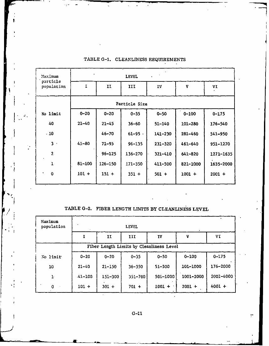
I.
TABLE G-1. CLEANLINESS REQUIREMENTS
M'a' imum LEVEL"particle..... . . .
population II III IV V VI
Particle Size
NO limit 0-20 0-20 0-35 0-50 0-100 0-175
40 21-40 21-45 36-60 51-140 101-280 176-540
10 46-70 61-95 141-230 281-460 541-950
3 41-80 71-95 96-135 231-320 461-640 951-1270
2 96-125 136-270 321-410 641-820 1271-1635
1 81-100 126-150 171-350 411-500 821-1000 1635-2000
0 101 + 151 + 351 + 501 + 1001 + 2001 +
TABLE G-2. FIBER LENGTH LIMITS BY CLEANLINESS LEVEL/
Maximumpopulation LEVEL
III IV V Vi
Fiber Length Limits by Cleanliness Level
No limir 0-20 0-20 0-35 0-50 0-100 0-175
10 21-40 21-150 36-350 51-500 101-1000 176-2000
-41-100 151-300 351-700 501-1000 1001-2000 2001-4000
0 01 + 301 + 701 + 1001 + 2001+ 4001 +
G-11
u . Ope:,n vve to previously evacuated steel bottle and allow the pressure toequalize.!
c. Threal flask into tee or nipple as provided at the gauge connection on the pump.
d. Pump flask to between 50 to 60 psig, where applicable. The compressor re-quiies only a few minutes to bring the flask to this pressure, which is the maximum outputpressure of the pwnp.
e. Release pressure. Repeat pumping procedure three times. Do not releasepressure final time.
f. Close valve to flask
g. Turn off compressor.
Samples from high pressure gas -systems can be obtained by making suitable con-nections. Provision should be made so that the connection piping between the pressurizedsystem and sampling bottle can be well purged to allow collection of a valid sample.
Samples from pressurized capsules or storage flasks can be obtained directly with-out the use of a pump.
* Stainless steel bottles are generally rated for use only to 500 psig and extreme cau-tion must be used. If the source of gas is higher than 500 psig, assure that the bore -is "not filled beyond this rared pressure. In practice, a sample pressure of not more than 300psig is adequate.
G. 7. 3. 2 Analytical Procedures
It-is recommended that a total hydrocarbon analysis be performed-keeping aclose lookout for the -cleaning agent used. The total hydrocarbon analysis should be ob-tained on the sample using a gas chromatographic system equipped -ith a back-flush valve.An instrument capable of such a determination is the NRL Total Hydrocaibon Analyzerequipped with a flame detector and a silicone DC 200 column (see Appendix F). 'Mostcommercial-gas chromatographs equipped with a flame detector could be modified to -per-form the analysis. In the event that the total hydrocarbon value (excluding methane, basedon a n-hexane standard or equivalent) exceeds 15 mg/m 3 , the total hydrocarbon mixtureshould be analyzed further for specific contaminants. This is to provide analytical infor-mation as to the presence of specific compounds, such as benzene, which might be presentin unacceptable concentrations. The total hydrocarbon value of 15 mg/m 3 , -per se, shouldnot disallow the acceptance of the closed atmosphere. Detailed analyses can be done bynormal elution gas chromatuaraphy, mass spectrometry, infrared analysis or a combi-natiort of these techniques. The detection and determination of specific contaminants in thismanner is a difficult and time-consuming task.
G. 8 'MAINTAINING THE SYSTEM IN A CLEAN CONDITION
G. S. 1 Providing a Clean Gas
Care should be taken to provide a gas which- is cleaned to the necessary tolerancesof the system. Because of toxicological problems which-occure In conjunction uith chlorinatedhydrocarbons (see G. 5. 2 and G. 5.4), the supplier should certify in writing that either of
G-12
the following precautions have been taken:
a. The gas delivered has been analyzed, and contains no more than 0.1 ppm of
halovenated compounds (trichloroethylene, carbon tetrachloride, etc.)- Freon levels up
to 1. 0 ppm may be allowed.
b. That nowhere in the extraction, purification, storage, or handling of the
helium has it been exposed to the contaminants noted above or to containers or hardware
cleaned by them.
G. S. 2 Charging Filters
In order to prevent any contamination from entering the system during charging
procedures, a filter should be installed downstream from the charging connection as close
to the charging connection as possible.
E
L0
I
|
• -
G-13/(G-44 blank)
APPENDLX H
GENERAL GUIDELINES FOR DSS HANDLING SYSTEMS 4j
H. 1 INTRODUCTION
This appendix contains guidelines for the design of deep- submergence system handlingsystems. Recommended design cviteria are outlined'and methods of verification arediscussed.
H. 2 DEFINITIONS
by Added Mass Effect - Added force encountered when water is accelerated by a movingbody.
Critical Item - A critical item is any item within a system, equipment or component,where failure would endanger life.
Design Load - the combined force due to the rated load, dynamic load, added mass
effects, entrained water and drag.
Dynamic Load - the load imposed on a system due to weight and acceleration forces.
Fail-Safe - A fail-safe condition exists when the equipment has been designed so thatwhen the operating power source (electrical, pneumatic, hydraulic or any combination ofthese) fails, the equipment is, by design, in a condition that is safe for personnel.
Handling System - that system or subsystem of the deep submergence system which
is used in stowing, deploying, operating and retrieving the deep submergence system and isdirectly related to safety of DSS personnel.
Rated Capacity - the gross weight which devices can safely handle (i. e. lift, move,' restrain) and still meet the requirements of the specifications (synonymous with capacity and
safe working load).
Rated Load - the weight in air of the payload being handled plus the weight ofall items normally carried by the payload.
Safety Factor - A constant equal to the ratio of either the yield or the ultimate strengthA , of a material to the stress at the design load.
Static Load - Weight in air of' ,e payload.
H.3 DESIGN-CRITERIA
H. 3.1 Operational Considerations
a. Environment - Environmental factors which should be considered in handlingsystem design include sea-state, air temperature, water temperature, precipitation, visi-bility at depth, wind velocity, and current. For the operationai sea state specified, theuppermost value for wave heights of the significant wave or the 1/10th highest wave should betaken as the design wave. The period of maximum energy of the sea spectrum should bechosen as the design period.
H-.i
b. lfandlin. .;%stems shouli operate so that deployment and retrieval of equip-nenit at sea can be av-omplished wtthout the aid of divers, whenever possible.
c. Operation in a Damaged Condition - The handling system should remain opera-l .Aff:"- v sustaining sktrin damage. Equipment and machinery should be capable of operatingtaiisf',ctorily, maintaining adequate lubrication, and avoiding loss of oil or other vital fluidsulder the following conditions (these conditions should be specified by the designer):
(1) Ship permanently trimmed down by the bow or stern.
(2) Ship permanently listed to either side of vertical.
In addition, all h.mdling system equipment should be operable under normal ship roll,pitch md heave conditions. These conditiors should also be specified by the designer. Equip-ment should also be designed so that they can be operated manually in the event of a poweror control failure and should be designed to be fail-safe.
d. Emergency Retrieval - Handling systems for DSS should have emergency
retrieval operations capability.
IT.3.2 Equipment Considerations
a. Loading
- (1) Design Load - In cases where all of the design load effects are not experi-enced simultaneously, handling systc-n components should be sized according to the highestdesign load condition that will be encountered.
(2) Unsymmetrical loading - When sizing members for handling systemswhich o.mploy more than one load carrying member to support their payload, consideration:ihould be given to factors which might cause unsymmetrical loading in-the members. Suchfactors might be external water, free surface effects in internal tanks, or shift In ballast.To account for such unknown loading, a safe practice would be to increase the static loadcarried-by each member by 10% of its value.
b. Factors of Safety
Suggested factors of safety for handling systems are given in Table H-1 andset forth values for factors of safety relativc -t3 the material used and the operating environ-nontil conditions. These values are normin3l values based on engineering experience and,z dctices. Even though the design meets these suggested factors of safety, it does not;-0 eic e the applicant of the responsibility to provide material justification for each handling..sk'; component within the scope of certification.
Reproduced frombest available copy.
11-2
L

'II
TABLE H-I. MINIMUM VALUES OF FACTOR OF SAFETY
Material/ Manned Unmanned
Application Non-Critical Critical (For Comparison)Component Component (Only)
Cast iron * *6
Fracture-resistance steel 3 3.5 2.5
Fracture-sensitive steel 3.5 * 3
Aluminum 3 5 2.5
Wire rope standing rigging 4** 5** 3*
Wire rope running rigging 5** 6** 5**
Fittings 3 4 3
Natural and synthetic rope 6** 7** 4**
* Not to be used in manned handling systems.
c, Materials
(1) D6fects - Materials should be free from any defects and imperfectionswhich-might affect serviceability of the handling system.
(2) Material Compatibility - Bimetallic construction in handling system equip-ment that will be immersed in sea water should be avoided whenever possible. Whenevernecessary, materials should be selected with consideration to their position on the electro-motive scale.
(3) Corrosion - Design of handling system equipment should be such as -toeliminate hazards of parts becoming inoperative due to corrosive and wetting effects of saltspray and the extreme environmental conditions encountered in an exposed location on theweather deck of a ship. To prevent wire rope from corroding prematurely, synthetic coatingsshould be avoided. If a chafing material is needed, removable coatings should be used sovisual inspection of the wire rope can be accomplished.
d. Automatic Release and Hook-Up-System - The payload release and hook-upsystem should be automatic.
e. Load Control - Means should be provided by which the motion of the payload,particularly pendulum action, can be controlled by the handling system when the payload issuspended from the ship in a seaway.
H-3
f. Shock Mitigating Device - A means of controlled tensioning should be providedto reduce or prevent shock loading on the payload and the handling system due to surge in aseaway.
g. Naval Architecture
(1) Handling systems should be designed io be as light weight and compactas practical. Consideration should be given to the effect of the handling system on shipweight and stability.
(2) Handling system equipment should be located such as to be minimallyaffected by the ship's roll, pitch, and heave.
•H. 4 VERIFICATION OF ADEQUACY
H. 4.1 Required Documentation
a. All components of the handling system within the c frtilcatilm scope should beIdentified as being either critical or non-critical..
b. The material adequacy of all handling system components within the certifica-tion scope which arc in the critical category should be documented.
c. Design Calculations - Design calculations should include the followingdocuments:
(1) An overall systems free-body schematic.
(2) A table indicating the various loading conditions used in the analysis.
(3) A load path analysis diagram showing how components of the system areloaded.
(4) When analyzing a critical component (see Table H-1), a free-body diagramof the item should be clearly shown within the calculation.
(5) Equations, assumptions and factors of safety used in the calculation/ should be clearly indicated.
H.4.2 Testing
Handling systems should be tested according to the following procedures:
a. Static test - The handling system equipment should be static tested to twice thedesign load of the specific piece of equipment. This load should be held for ten minutes.The static load should then be lowered with Intermittent stopping to demonstrate the holdingcapacity of the brake. No visible permanent deformation should result from this test.
b. Overload - The handling system should be run-through one complete cycle ofits operation with 150 percent of the design load. A complete cycle would include unloadingfrom the stowed position into the water, releasing, retrieving and restowing.
H-4

* ~1
c. Rat A - The handling system should be run through at least one completecycle of its operatiu with its rated load. This test must be run at the specified operationalspeed of the equipment.
d. Non-Destructive Testing - Non-destructive test techniques should be employedto insure the soundness and quality of the handling system fabrication.
H-5/(H-6 blank)
APPENDIX J
BIBLIOGRAPHY
The publications listed below are representative of those which may be useful to theapplicant in preparing his DSS design for material certification. The most recent issue orrevision of each should be used.
ASA B 31.1, Code to Pressure Piping
ASME Boiler and Pressure Vessel Code, Section II, Material Specifications
ASME Boiler and Pressure Code, Section 1II, Nuclear Vessels
ASME Boiler and Pressure Vessel Code, Section VII and Division 1, Unfired PressureS""Vessels, and Division 2, Alternative Rules for Pressure Vessels
ASME Boiler and Pressure Vessel'Code, Section IX, Welding Qualifications
BUMED Instruction 6260.6B, Hearing Conservation Program
BUMED Instruction 6270.3D BUMED letter SER 606 of 7 June 1969
Compressed Gas Association Pamphlet G-4.2, Standard for Bulk Oxygen Systems at ConsumerSites
Compressed Gas Association Pamphlet V-5, Diameter-Index Safety System
IEEE Publication 45, Recommended Practice for Electric Installations onShipboard
MIL-B-16541, Bronze, Valve, Castings
MIL-B-23921, Bronze, Nickel Aluminum, Castings for Seawater Service
MIL-B-24059, Bronze, Nickel Aluminum, Rod Flat Products with Finished Edges, Shapesand Forgings
MIL-B-36212, Baralyme
MIL-C-15726, Copper-Nickle Rod, Flat Products, Flat Wire, Strip, Sheet Bar, Plate andForgings
MIL-C-20159, Copper-Nickel Alloy 70-30 and 90-10, Castings
MIL-D-16791, Detergents, General Purpose (NonIonic)
1.L-E -917 , Electric Power Equipment. Basic Requirements-for Naval Shipboard use
MIL-E-16400, Electronic Equipment, Naval Ship and Shore, General Specification
MIL-F-22606, Flask, Compressed Gas and End Plugs for Air, Oxygen and Nitrogen
J-1
MIL-I-6siG, Inspection, Penetrant Method of
Ml L-l -6S,3, Inspection, Process, Magnetic Particle
MIL-L-20213, Lithium Hydroxide, LiOH, Technical
MIL-M-16576, Metal, Gun, Castings
MIL-0-9S58A, Quality Program Requirements
MIL-S-3289A, Steel, Plate and Disk, Carbon, Forging Quality
MIL-S-16216, Steel Plate, Alloy, Structural, High Yield Strength, HY-80 and HY-100
MIL-S-23008, Steel Castings, Alloy, High Yield Strength, HY-80 and HY-100
MIL-S-23009A, Steel Forgings, Alloy, High Yield Strength, HY-80 and HY-100
fIlL-S-24094 use MIL-S-16113, Steel Plate, High Tensile, Hull and Structural
MIL-T-1368, Tube and Pipe, Nickel-Copper Alloy, Seamless and Welded
MIL-T-16 420, Tube, 70-30 and 90-10, Copper-Nickel Alloy, Seamless and Welded
MIL-V-24287, Sea Water Valves
MIL-STD-101, Color Code for Pipelines and for Compressed-Gas Cylinders
MIL-STD-210, Climatic Extremes for Military Equipment
MITL-STD-271, Non Restrictive Testing Requirements for Metals
MIL-STD-453, Inspection, Radiographic
MIL-STD-767, Cleaning Requirements for Special Purpose Equipment including Fire Systems
MIL-STD-882, System Safety Program for Systems and Associated Subsystems and Equipment,Requirements for
MIL-STD-1246, Production Cleanliness Levels and Contamination Control Program
1IL-S'. J-1247, Markings, Functions and Hazards Designations of Hose, Pipe and TubeLines for Aircraft, Missile, and Space Systems
MIL-STD-1330, Cleaning and Testing of Oxygen and Nitrogen Gac 1iping Systems
MTL-STD-1359, Cleaning, Methods and Procedures for Breathing Oxygen Equipment
MIL-STD-00248 (SHIPS), Welding and Brazing Procedure and Performance Qualification
IS-1 116, Bolt, Bolt-Stud, Stud, Saud-, Nickc!-Copper-A, L.... .Aoy, ecl
Requirements
MS-33586, Metals Definition of Dissimilar
J-2
BUSHIPS Instruction 9230.12A, Cleaning Procedures, Oxygen and Nitrogen Systems
BUSHIPS Instruction 9490.6, Shipboard High Pressure Compressor Air Systems-Inspect toDetermine Need to Clean
BUSHIPS Instruction 9490.4B, Shipboard High Pressure Compressed Air Systems, PeriodicCleaning and Procedures for Cleaning to Prevent Fires and Explosions
BUSHIPS Instruction 9490.9, Procedure for Cleaning, Inspection and Coating High PressureAir Flasks and Moisture Separators
NASA Management Instruction KMI 8610.6 (March 24, 1968), Attachment A; Minimum Criteria• for Operations Involving Personnel in a Vacuum, Oxygen-Rich, or Potentially Oxygen-Rich
Environment
NASA Spec 10509318 (MSFC), Hose Assemblies, Flexible, High Pressure, Specification for
S"NASA Spec MSC-SPEC-C-6B, Spacecraft chemical and cleanliness Requirements
NASA Spec MSFC-SPEC-164, Cleanliness of Components for use in Oxygen, fuel andPneumatic Systems
National Bureau of Standards Handbook H28
NASA Spec KSC-123 (D), Cleanliness Levels Cleaning Protection and Inspection Proceduresfor Parts, Field Parts, assemblies, subassemblies and systems for pneumatic use insupport equipment
NAVEXOS P422, Safety Equipment Manual
NAVSHIPS 0900-01-7000, Fabrication and Inspection of Brazed Piping Systems
NAVSHIPS 0900-006-9010, Fabrication, Welding and Inspection of HY-80 Submarine Hulls,Section 4
NAVSHIPS 0900-028-2020, Pre-Survey Outline Booklet for Manned, Non-Combatant Sub-mersibles
/ 0
NAVSHIPS 0994-001-9010, U.S. Navy Diving Manual
NAVSHPS 0994-003-7010, U.S. Navy Diving Gas Manual
XRL Report 6957, Evolution of Engineering Principles for Fracture-Safe Design of SteelStructures, W. S. Pellini, September 23, 1969 (Naval Research Laboratory, Washington,D.C. 20390)
Ocean Systems, Incorporated, Report (May 1, 1969): Region of Non Combustible, Flamma-bility Limits of Hydrogen-Oxygen Mixtures, Full-Scale Combustion and Extinguishing Testsand Screening of Flame-Resistant Materials
QQ-N-281, Nickel-Copper Alloy, Monel and R Monel, Bars, Plates, Rods, Sheets, Strips,* Wire, Forgings and Structural and Special Shaped Sections
QQ-N-286, Nickel-Copper-Aluminum Alloy, Wrought
J-3

QQ-N-2S8, Nickel-Copper Alloy and Nickel-Copper-Silicon Alloy, Casting
QQ-S-A91C, Steel Plate, Carbon-Silicon, Carbon-Molybdenum, and Manganese-M olybdenum Alloys, Hot-Rolled (Marine Boiler Quality)
USAS B31.7, USA Standard Code for Pressure Piping, Nuclear Power Piping
USAS B57.1 - 1935, Compressed Gas, Cylinder Valve Outlet and Inlet Connections
-J-4
__I