Embed Size (px)
Citation preview
Ad-hoc Integration of
Annotated Services to Instances
of a Meta-model of Interactive
Service-based Applications
Großer Beleg
am Institut fur Systemarchitektur
vorgelegt von: Georg Berndt
Studiengang: Medieninformatik
Matrikelnummer: 3017039
Hochschullehrer: Prof. Dr. rer. nat. habil. Dr. h.
c. Alexander Schill
Betreuer: Dipl.-Inf. Marius Feldmann
Dresden, 2009


Themenstellung


Eidesstattliche Erklarung
Ich versichere hiermit, dass ich meine Belegarbeit mit dem Thema
Ad-hoc Integration of Annotated Services to Instances of a Meta-
model of Interactive Service-based Applications
selbstandig verfasst und keine anderen als die angegebenen Quellen und Hilfs-
mittel benutzt habe. Die Arbeit wurde bisher keiner anderen Prufungsbehorde
vorgelegt und auch nicht veroffentlicht.
Dresden, den 11.12.2009
Georg Berndt


Abstract. The implementation of business processes based on service-oriented
architectures is well-understood and covered by existing development approaches.
To enable a mainly automatic creation of service-based interactive applications,
service descriptions have been extended by so called UI-related service anno-
tations. These are information fragments expressing user-interface related as-
pects. Within this thesis a service scenario will be presented, which requires an
ad-hoc integration of services into interactive applications. Based on this sce-
nario requirements are analyzed that are used to develop a system architecture
supporting the ad-hoc integration of services into an instance of a Meta-model
for representing service-based interactive applications. This system is imple-
mented prototypically. During a practical study based on the implementation
and the introduced scenario, the concept is evaluated proving its feasibility.
Furthermore the approach is compared to a second approach that has been
developed within [Mar09].
Keywords. services, composition, annotations, interactive applications, MDA

Contents
Contents
1. Introduction 1
1.1. Motivation . . . . . . . . . . . . . . . . . . . . . . . . . . . . . . 1
1.2. General Approach . . . . . . . . . . . . . . . . . . . . . . . . . . 1
1.3. Structure of the Thesis . . . . . . . . . . . . . . . . . . . . . . . 3
2. Analyses 4
2.1. Home Scenario . . . . . . . . . . . . . . . . . . . . . . . . . . . 4
2.2. Requirements . . . . . . . . . . . . . . . . . . . . . . . . . . . . 7
3. State of the art 9
3.1. Fundamentals . . . . . . . . . . . . . . . . . . . . . . . . . . . . 9
3.1.1. Description Formats . . . . . . . . . . . . . . . . . . . . 9
3.1.2. Application Meta-Model . . . . . . . . . . . . . . . . . . 11
3.1.3. Related Approach . . . . . . . . . . . . . . . . . . . . . . 12
3.2. State of the Art Analysis . . . . . . . . . . . . . . . . . . . . . . 13
3.2.1. Scaffolding . . . . . . . . . . . . . . . . . . . . . . . . . . 13
3.2.2. XML Forms Generator . . . . . . . . . . . . . . . . . . . 14
3.2.3. WSGUI . . . . . . . . . . . . . . . . . . . . . . . . . . . 14
3.2.4. Dynvoker . . . . . . . . . . . . . . . . . . . . . . . . . . 15
3.2.5. Approach of He and Yen . . . . . . . . . . . . . . . . . . 16
3.2.6. MARIA Authoring Environment . . . . . . . . . . . . . 16
3.2.7. Conclusion . . . . . . . . . . . . . . . . . . . . . . . . . . 17
4. Concept and Realization 19
4.1. Architectural Concept . . . . . . . . . . . . . . . . . . . . . . . 19
4.1.1. WSDL-Parser . . . . . . . . . . . . . . . . . . . . . . . . 20
4.1.2. Annotation-Parser . . . . . . . . . . . . . . . . . . . . . 21
4.1.3. Client-Composer . . . . . . . . . . . . . . . . . . . . . . 22
4.1.4. Model-Generator . . . . . . . . . . . . . . . . . . . . . . 23
i
Contents
4.1.4.1. Operation-Filter . . . . . . . . . . . . . . . . . 24
4.1.4.2. User-Interface-Configuration . . . . . . . . . . . 24
4.1.4.3. Platform-Definition-Component . . . . . . . . . 25
4.2. Realization . . . . . . . . . . . . . . . . . . . . . . . . . . . . . 25
4.2.1. WSDL-Parser . . . . . . . . . . . . . . . . . . . . . . . . 25
4.2.2. Annotation-Parser . . . . . . . . . . . . . . . . . . . . . 27
4.2.3. Client-Composer . . . . . . . . . . . . . . . . . . . . . . 28
4.2.4. Model-Generator . . . . . . . . . . . . . . . . . . . . . . 29
4.2.4.1. Service Data Representation . . . . . . . . . . . 31
4.2.4.2. Domain Specific Languages OFL and UIL . . . 32
4.2.4.3. Platform Definition Component . . . . . . . . . 40
5. Implementation 42
5.1. Web Services . . . . . . . . . . . . . . . . . . . . . . . . . . . . 42
5.2. WSDL-Parser . . . . . . . . . . . . . . . . . . . . . . . . . . . . 44
5.3. Annotation-Parser . . . . . . . . . . . . . . . . . . . . . . . . . 44
5.4. Client-Composer . . . . . . . . . . . . . . . . . . . . . . . . . . 47
5.5. Model-Generator . . . . . . . . . . . . . . . . . . . . . . . . . . 50
5.5.1. DSL-Interpreter . . . . . . . . . . . . . . . . . . . . . . . 53
5.5.1.1. OFL-Interpreter - as DSL-Interpreter Example 54
5.5.2. Service Data Representation . . . . . . . . . . . . . . . . 57
5.5.3. User-Interface Components . . . . . . . . . . . . . . . . . 59
5.5.4. Interactor Creation and Platform Definition . . . . . . . 63
6. Evaluation 68
6.1. Evaluation of the Prototype . . . . . . . . . . . . . . . . . . . . 68
6.2. Evaluation of the Requirements . . . . . . . . . . . . . . . . . . 75
6.3. Comparison of the different Approaches . . . . . . . . . . . . . . 76
6.3.1. Efficiency Measurement . . . . . . . . . . . . . . . . . . 77
6.3.2. Qualitative Comparison . . . . . . . . . . . . . . . . . . 79
7. Summary and Future Work 81
A. Appendix I
A.1. Domain Specific Languages . . . . . . . . . . . . . . . . . . . . I
A.1.1. OFL Specification . . . . . . . . . . . . . . . . . . . . . . I
ii

Contents
A.1.2. UIL Specification . . . . . . . . . . . . . . . . . . . . . . III
List of Figures IV
List of Tables V
Listings VI
Bibliography VII
iii

Contents
iv
1. Introduction
1.1. Motivation
A Service-Oriented Architecture (SOA) describes a pattern for structuring and
usage of distributed functionalities which are maintained by different propri-
etors. This service-oriented concept operates well for adapted client and server
applications that use their service descriptions to exchange data via eXtended
Markup Language (XML) messages. In contrast to this Business-to-Business
(B2B) orientation, the Business-to-Consumer (B2C) support which allows a
user to access a service directly lacks of fundamental features. Web services do
not provide a User Interface (UI), so an additional UI generation for web ser-
vices is required to enable human machine interaction. Although there already
exist approaches for generating UIs from service descriptions, these approaches
lack of the ability to apply advanced UI features.
1.2. General Approach
In order to prevent this lack of service-consumer-orientation, the new approach
should be able to generate user interfaces from standardized service descrip-
tions such as Web Service Definition Language (WSDL). Furthermore, addi-
tional features will extend the simple UI to a platform specific application,
supporting a majority of its offered functionalities. These additional features,
like client side input validation, input suggestions but also layout assignments
will afford the same Look and Feel, the user is inured from other platform spe-
cific applications. For this purpose the service descriptions have to be extended
by additional information.
1
1. Introduction
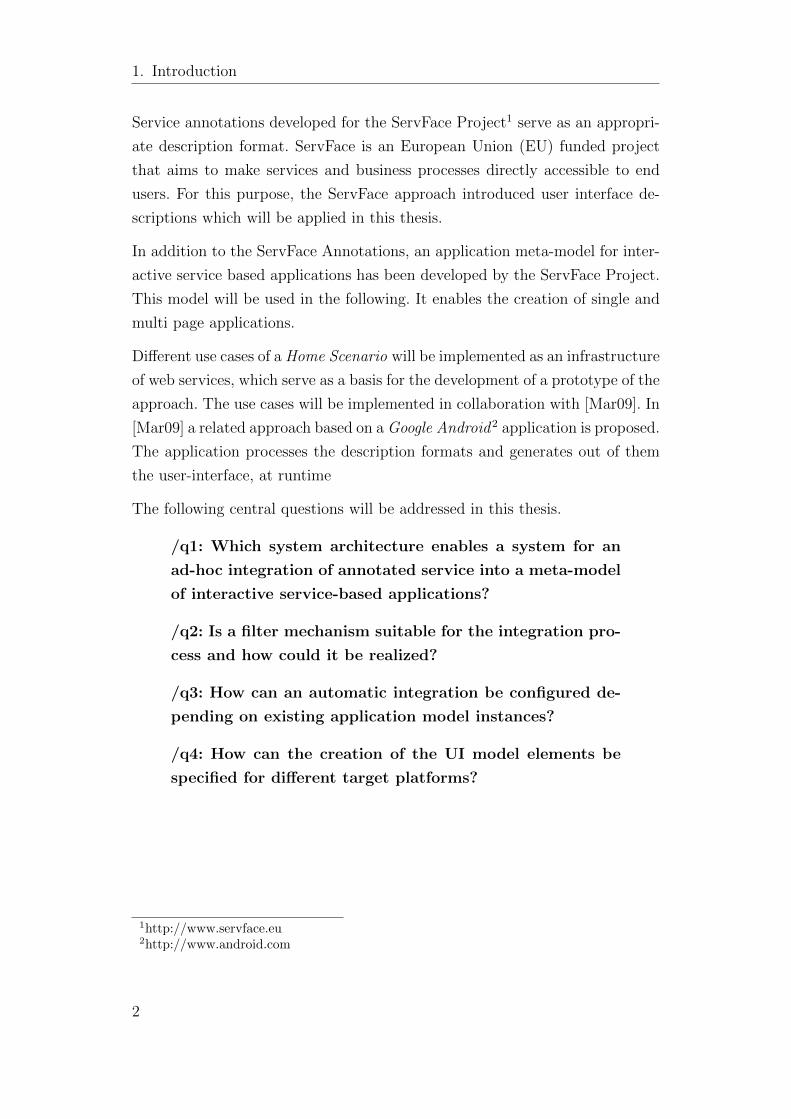
Service annotations developed for the ServFace Project1 serve as an appropri-
ate description format. ServFace is an European Union (EU) funded project
that aims to make services and business processes directly accessible to end
users. For this purpose, the ServFace approach introduced user interface de-
scriptions which will be applied in this thesis.
In addition to the ServFace Annotations, an application meta-model for inter-
active service based applications has been developed by the ServFace Project.
This model will be used in the following. It enables the creation of single and
multi page applications.
Different use cases of a Home Scenario will be implemented as an infrastructure
of web services, which serve as a basis for the development of a prototype of the
approach. The use cases will be implemented in collaboration with [Mar09]. In
[Mar09] a related approach based on a Google Android2 application is proposed.
The application processes the description formats and generates out of them
the user-interface, at runtime
The following central questions will be addressed in this thesis.
/q1: Which system architecture enables a system for an
ad-hoc integration of annotated service into a meta-model
of interactive service-based applications?
/q2: Is a filter mechanism suitable for the integration pro-
cess and how could it be realized?
/q3: How can an automatic integration be configured de-
pending on existing application model instances?
/q4: How can the creation of the UI model elements be
specified for different target platforms?
1http://www.servface.eu2http://www.android.com
2
1.3. Structure of the Thesis
1.3. Structure of the Thesis
This thesis is divided into six chapters on Analysis (2), State of the Art (3),
Concept and Realization (4), Implementation (5), Evaluation (6), and Sum-
mary and Future Work (7).
In a first step and in order to achieve solutions for the listed questions, a de-
tailed analysis of the environment and the requirements build the foundation
for this thesis in chapter 2. The obtained characteristics will then be used to
differentiate between the own approach and existing approaches by use of a
state of the art analysis in chapter 3. This investigation leads to a compar-
ison of all approaches regarding the requirement characteristics. After these
preparatory work steps, the general concept and realization issues, first will
be presented in detail in chapter 4 and after that seamlessly initiate certain
implementation decisions in chapter 5. Then in the evaluation, chapter 6, the
accomplishment will be proofed of the basic goals and generally the chosen
concept in contrast to other approaches. At least a summary, chapter 7, is
used to compress the gained knowledge in retrospect which leads to a prospect
of future work.
3
2. Analyses
2. Analyses
This chapter is concerned with the preparatory analyses of the environment and
requirements for the prototypical implementation of the generator application.
First, the scenario and use cases will be acquired. These use cases lead to a
derivation of certain requirements.
2.1. Home Scenario
A home scenario requires a connectivity between heterogeneous devices within
a home network. For this purpose a service oriented architecture can be used,
where each device provides its functionalities via web service. SOAP serves
as communication protocol and enables remote invocations between these net-
work devices by use of XML messages. Such a home scenario serves as an
appropriate example for a dynamic service infrastructure where a simple di-
rectory service administrates the network access by mapping device names to
network addresses.
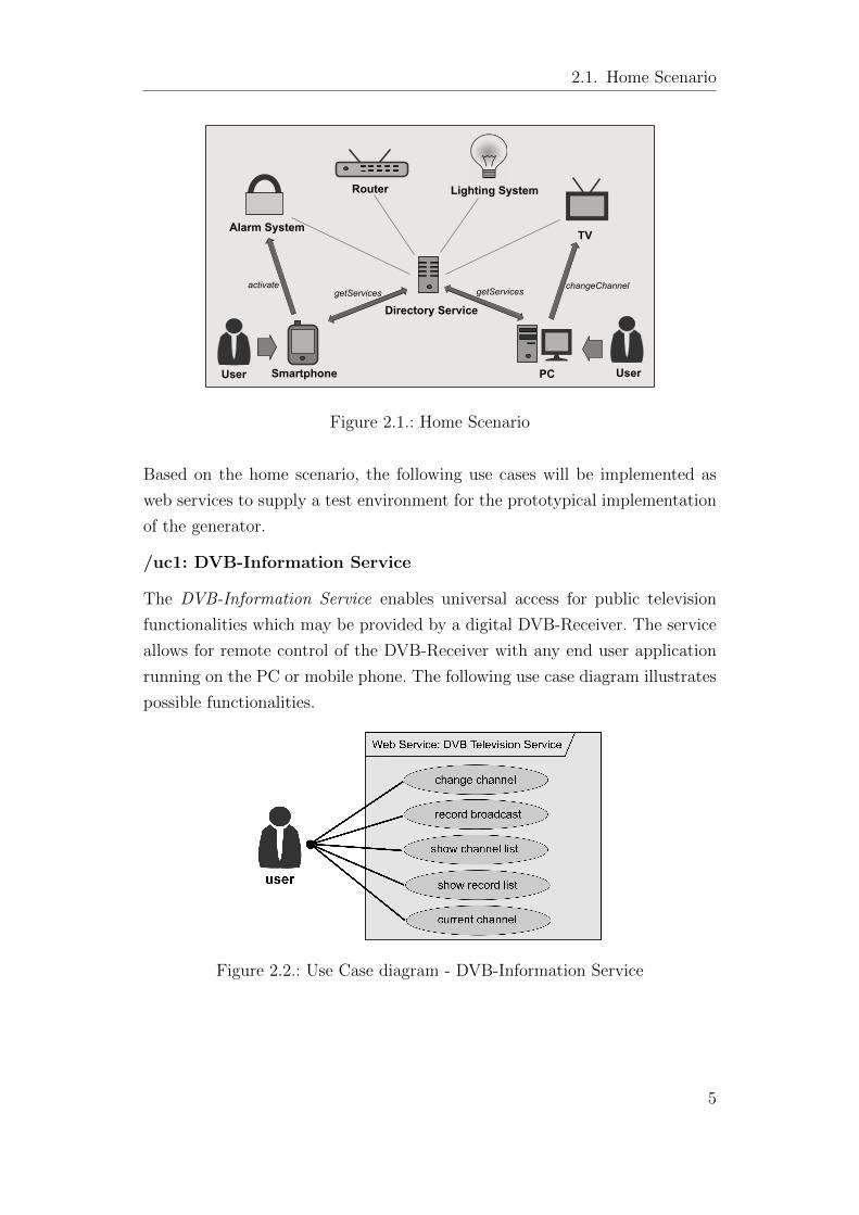
Figure 2.1 shows an example of a home scenario with the service-providing
devices Alarm System, Router, Lighting System and TV. The Directory Service
manages the provided services of the home network and serves as a central
communication point to get the list of available service-providing devices and
their services. In order to get access to these services by an end user device,
such as a PC or Smartphone, first a request to the Directory Service is required
to get available home network services. Then, the invocation of certain service
operations like activating the Alarm System or switching the TV channel by
end user devices is possible.
4
2.1. Home Scenario
Directory Service
Lighting System
Alarm SystemTV
PC User
Router
User Smartphone
getServicesgetServicesactivate changeChannel
Figure 2.1.: Home Scenario
Based on the home scenario, the following use cases will be implemented as
web services to supply a test environment for the prototypical implementation
of the generator.
/uc1: DVB-Information Service
The DVB-Information Service enables universal access for public television
functionalities which may be provided by a digital DVB-Receiver. The service
allows for remote control of the DVB-Receiver with any end user application
running on the PC or mobile phone. The following use case diagram illustrates
possible functionalities.
Figure 2.2.: Use Case diagram - DVB-Information Service
5
2. Analyses
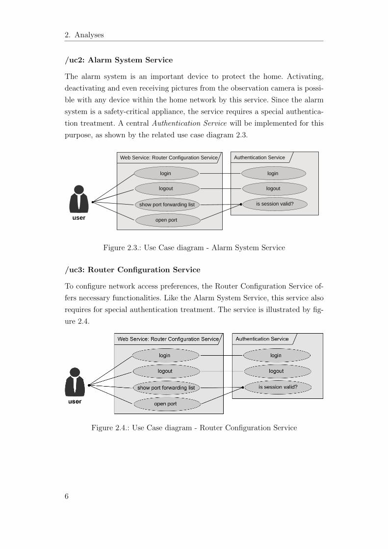
/uc2: Alarm System Service
The alarm system is an important device to protect the home. Activating,
deactivating and even receiving pictures from the observation camera is possi-
ble with any device within the home network by this service. Since the alarm
system is a safety-critical appliance, the service requires a special authentica-
tion treatment. A central Authentication Service will be implemented for this
purpose, as shown by the related use case diagram 2.3.
user
Web Service: Router Configuration Service
login
Authentication Service
show port forwarding list
open port
logout
login
logout
is session valid?
Figure 2.3.: Use Case diagram - Alarm System Service
/uc3: Router Configuration Service
To configure network access preferences, the Router Configuration Service of-
fers necessary functionalities. Like the Alarm System Service, this service also
requires for special authentication treatment. The service is illustrated by fig-
ure 2.4.
Figure 2.4.: Use Case diagram - Router Configuration Service
6
2.2. Requirements
2.2. Requirements
/r1: Ad-hoc integration of annotated web services to instances of the
application meta-model
The main functional requirement is the integration of annotated web services
to instances of the ServFace Composite Application Model (CAM) (see 3.1.2).
An instance must be extensible to other services. Already contained services
must be updatable.
/r2: Parameterization of the integration
The integration must be adjustable. One must be able to define at which point
the services are inserted into the instance. It must also be possible to define the
target language, target platform and several parameters for the presentation,
such as the maximal number of UI elements on a Page.
/r3: Integration of selected ServFace Annotations
In addition to the integration, a number of ServFace Annotations will be im-
plemented exemplary to enrich the simple web service user interface by special
user interface features. The ServFace Annotations Model and its XML Anno-
tations descriptions build the foundation for this purpose.
/r4: Filtering of web service operation
There must be a mechanism that enables filtering of web service operations by
definable rules.
/r5: Support of several target platforms
The application model includes interactors, which are mapped to user interface
elements of different platforms. Depending on the platform, it must be possible
to define the required interactors and their parameters. It should be possible
to add new platforms and to change the definition of existing platforms.
/r6: Generality
The System should be able to generate a user interface for any web service
which is annotated with ServFace Annotations and uses the WSDL specifica-
tion 1.1 for the definition of its service functionalities.
7

2. Analyses
/r7: Modularity
The system should allow for changes e.g. when the service or user interface
descriptions need to be extended. For this purpose a modularized architecture
of the interpreter will be adopted.
8
3. State of the art
This chapter is concerned with already existing approaches for user interface
generation and will present, firstly, some fundamentals relating to the descrip-
tion of annotated services and the description of interactive service based ap-
plications. During this presentation a short overview of the related approach
described in [Mar09] is given. Secondly, a pure inference mechanism-based at-
tempt will be presented (XML Forms Generator). This approach builds the
basis for the subsequently introduced approaches using additional user inter-
face information. At the end of this chapter the approach developed in the
course of this thesis will be classified by similarities and differences in regard
to the envisaged approaches.
3.1. Fundamentals
3.1.1. Description Formats
To accomplish a dynamic user interface generation for web services, public
information about web services in the form of WSDL files are required. The
WSDL file is a standardized XML description for web services. Beside the
definition of service operations, parameters and data types, HTTP-based ser-
vice invocation is defined by binding properties. This information facilitates
the generation of a user interface. Such generation of a user interface from a
formal model is known as inference mechanism-based UI generation.
Since the WSDL file represents an programming interface description of a web
service, element labels are obtained from the service implementation. This
matter of fact restrains the usability of the generated user interface heavily,
as in general operation and parameter names used for the implementation are
not convenient to create comprehensible user interfaces. To compromise this
9
3. State of the art
disadvantage, additional user interface descriptions have to be considered for
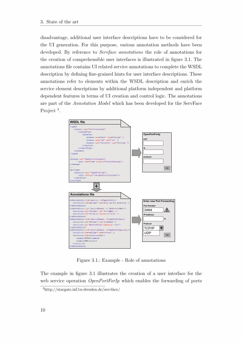
the UI generation. For this purpose, various annotation methods have been
developed. By reference to Servface annotations the role of annotations for
the creation of comprehensible user interfaces is illustrated in figure 3.1. The
annotations file contains UI related service annotations to complete the WSDL
description by defining fine-grained hints for user interface descriptions. These
annotations refer to elements within the WSDL description and enrich the
service element descriptions by additional platform independent and platform
dependent features in terms of UI creation and control logic. The annotations
are part of the Annotation Model which has been developed for the ServFace
Project 3.
OpenPortForIp port
ip
protocol
OK
Enter new Port Forwarding Port Number 45M4
IP-Address
Protocol
OK
*TCP/IPUDP
34M4
WSDL file
Annotations file
+
Figure 3.1.: Example - Role of annotations
The example in figure 3.1 illustrates the creation of a user interface for the
web service operation OpenPortForIp which enables the forwarding of ports
3http://stargate.inf.tu-dresden.de/servface/
10
3.1. Fundamentals
for certain IP addresses. All parts of the WSDL file which are relevant for
the creation of the user interface are shown in the example WSDL file. This
description facilitates the generation of a user interface, but the significance
and usability are restricted as shown in the first user interface. This drawback
can be remedied by including annotations into the generation process. The
annotations file defines reference objects which refer to elements from the
WSDL file by use of an ID. This additional information facilitates a much more
detailed description of the user interface elements. Beside the customization
of labels, features such as validation, mandatory field check and enumerations
can be realized as shown in the second user interface.
3.1.2. Application Meta-Model
The annotated services build the foundation for the composition of interactive
applications. For this purpose a application model for interactive service based
applications is needed. In addition to the ServFace Annotations, a Composite
Application Model (CAM) has been developed within the ServFace Project,
which will be used during this thesis. The CAM enables the definition of pages,
included UI fragments, and a page flow between these pages. Consequently,
single and multi page applications can be described. The authors of [FJN+09]
describe the CAM as follows.
A CAM describes the aspects of an interactive application and can be trans-
formed into executable code, which implements the interactive application through
model-to-code transformations in a process called runtime generation.
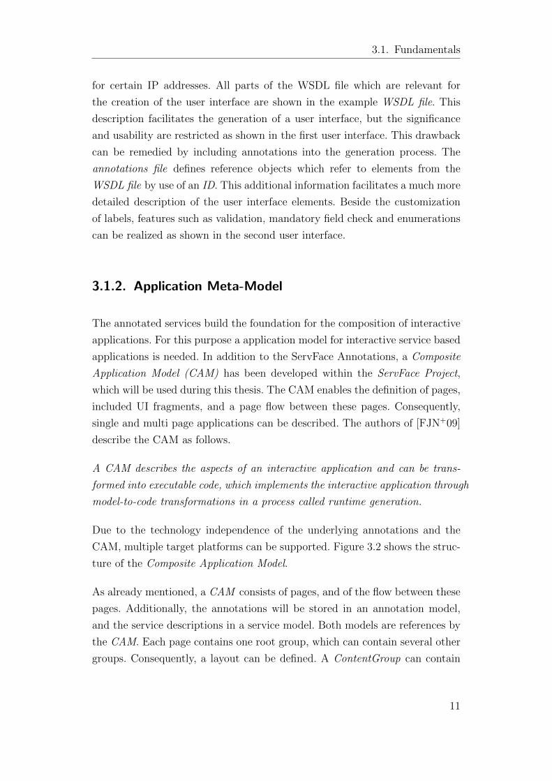
Due to the technology independence of the underlying annotations and the
CAM, multiple target platforms can be supported. Figure 3.2 shows the struc-
ture of the Composite Application Model.
As already mentioned, a CAM consists of pages, and of the flow between these
pages. Additionally, the annotations will be stored in an annotation model,
and the service descriptions in a service model. Both models are references by
the CAM. Each page contains one root group, which can contain several other
groups. Consequently, a layout can be defined. A ContentGroup can contain
11
3. State of the art
Figure 3.2.: Composite Application Model
interactors, which may trigger a flow transition. Such an interactor may also
invoke a service operation, whose result can influence the flow transition.
Essentially, the Composite Application Model can be used to describe an inter-
active service based application by using pages containing interactors, which
will be created by using the annotations. The flow, which will be derived from
the service structure and special annotations will be used to connect the pages
to each other.
3.1.3. Related Approach
As already mentioned, parallel to this elaboration the author of [Mar09] works
at an user-interface interpreter for annotated web services, which evaluates and
interprets ServFace Annotations for a service integration and presentation. The
interpreter will be developed prototypically as stand-alone application for An-
droid and consists of a WSDL Parser parsing the service description file, an
Annotation Parser parsing the service annotations, and the main component,
the Android-Interpreter, which implements an inference mechanism in order
to provide user interfaces for web services. Since the field of application for
the interpreter is a dynamic service infrastructure, the interpreter has to facil-
itate an ad-hoc generation of the user interface at runtime. Due this fact that
both thesis have the same problem space, some concepts and the resulting im-
plementations have been developed in collaboration. This mainly includes the
parsers for the service descriptions formats and a test environment consisting
12
3.2. State of the Art Analysis
of various annotated web services. Both approaches relating to the advantages
and disadvantages will be compared to each other in the evaluation chapter
(6.3).
3.2. State of the Art Analysis
In the following some selected approaches from the field of automatic UI gener-
ation are presented. Although there exist several other approaches, the decision
of the selection is based on the the following criteria: The first two approaches,
which are Scaffolding and XML Forms Generator, are intended to introduce
pure inference mechanism based techniques. Then, existing approaches of in-
cluding additional user interface descriptions are presented. For this purpose
the WSGUI concept and Dynvoker, which builds on WSGUI, seems most re-
lated to the concept of this thesis. Finally, the MARIA Authoring Environment
will be presented, which is an environment for building interactive service-based
applications by using a model-based user-interface description.
3.2.1. Scaffolding
Scaffolding describes a technique for building an application skeleton referred
to as scaffold from an underlying database model. This source code generat-
ing method includes the creation of a user interface for CRUD functionalities.
CRUD stands for the four basic access management operations Create, Re-
trieve, Update and Delete. So, scaffolding enables the generation of a fully
usable application only by defining the data description of the application.
This generated scaffold serves as starting point for the developer to build a
more powerful application. Scaffolding is an evolution of other database code
generators. During the last few years this method got very popular for the
development of Web-Applications especially by use of the open-source web
framework Ruby on Rails4(Rails). In general, there are two different Scaffold-
ing strategies: Dynamic Scaffolding and Scaffold generation. As the normal
4http://rubyonrails.org/
13
3. State of the art
Scaffold generation creates the application skeleton once at compile time, dy-
namic Scaffolding facilitates a dynamic generation at runtime. This method
of dynamic Scaffolding resembles a dynamic user interface generation, but as
Scaffolding is limited to CRUD functionalities the potential of this method is
restricted heavily. Moreover, dynamic Scaffolding does not offer the advantage
of using the generated scaffold as a template to build more powerful appli-
cations because the scaffold will be overwritten at runtime. Hence dynamic
scaffolding is no longer supported by Ruby on Rails since Rails version 2.0.
3.2.2. XML Forms Generator
The XML Forms Generator is a XML-based, data-driven approach which en-
ables the creation of XForms5-based forms from XML-data. The Eclipse6 plug-
in was developed by IBM Alphaworks7 and can be installed by the Eclipse In-
stall/Update Manager. XML Forms Generator is a pure inference mechanism-
based generator taking any XML instance document as input to create a usable
input form. The corresponding XML schema definition provides meta data such
as type constraints, length constraints or control types which are necessary to
build certain form constructs. Interestingly enough, the generator also supports
form generation for WSDL documents. That way, the tool enables simple and
direct user-service interaction just by use of a XForms renderer. As this method
is generating the user interface only including the WSDL document and ref-
erenced XML schema definitions, the intelligibility of the generated form is
heavily dependent on the description of these definitions. Another disadvan-
tage is apparent from the fact that the XML Forms Generator can exclusively
be applied from the plug-in menu within the Eclipse development environment.
Hence, a dynamic user interface generation is not applicable.
3.2.3. WSGUI
The concept of Web Services Graphical User Interface (WSGUI) developed
by [KKM03] at Stanford University was one of the first approaches of the
5http://www.w3.org/MarkUp/Forms/6http://www.eclipse.org7http://www.alphaworks.ibm.com/
14
3.2. State of the Art Analysis
dynamic generation of user interfaces for web services including additional
user interface description in the form of annotations. The concept provides for
a browser-based generation of comprehensible user interfaces and was seized by
various related approaches such as Dynvoker [Spi06]. User interface annotations
are defined by GUI Deployment Descriptor (GUIDD) documents. A GUIDD
contains form components which describe a mapping of XForms elements to
message instances of the WSDL file. For the creation of output UI elements,
special outputTypes can be defined, supporting the declaration of a MIME-
type. Furthermore, additional descriptions of service and operation elements
can be defined to create customized labels or facilitate a translation. Another
feature of GUIDD is the indication of style sheets, allowing for the adaptability
of the generated websites. All over, the GUIDD affects the creation of specific
UI elements, the layout and the embedding of the generated form in websites.
In order to facilitate the invocation of a web service a WSGUI engine requires
the WSDL file and the GUIDD file as input. By use of a XSLT processor a
website containing an input form is generated and forwarded to the user. After
submission the user input is sent back to the engine and transformed into an
applicable service request message. Finally, the engine acts as a proxy and
forwards the response after transforming the response message of the service
invocation into an appropriate website representation.
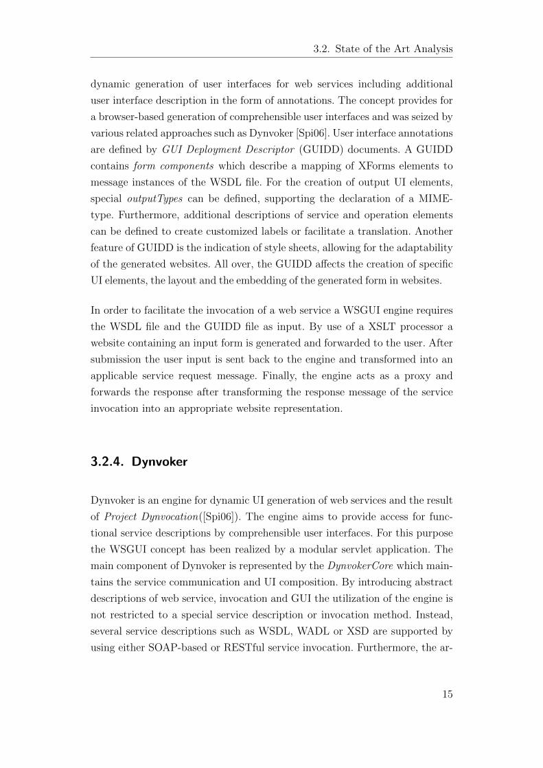
3.2.4. Dynvoker
Dynvoker is an engine for dynamic UI generation of web services and the result
of Project Dynvocation([Spi06]). The engine aims to provide access for func-
tional service descriptions by comprehensible user interfaces. For this purpose
the WSGUI concept has been realized by a modular servlet application. The
main component of Dynvoker is represented by the DynvokerCore which main-
tains the service communication and UI composition. By introducing abstract
descriptions of web service, invocation and GUI the utilization of the engine is
not restricted to a special service description or invocation method. Instead,
several service descriptions such as WSDL, WADL or XSD are supported by
using either SOAP-based or RESTful service invocation. Furthermore, the ar-
15
3. State of the art
chitecture of Dynvoker enables the generation of multiple output formats but
the current implementation concentrates on XForms in XHTML.
To enable a simple and platform-independent application of the engine, the ac-
cess is provided by a web page8. By specifying the URL of a service description
file and optionally a related GUIDD, a user interface for service exploitation
is generated. In a first step the names of service operations are listed and the
selection of an operation indicates an input form creation. After submission of
the input, the engine acts as an intermediate component managing the service
invocation and transformation of the response message as envisaged by the
WSGUI concept.
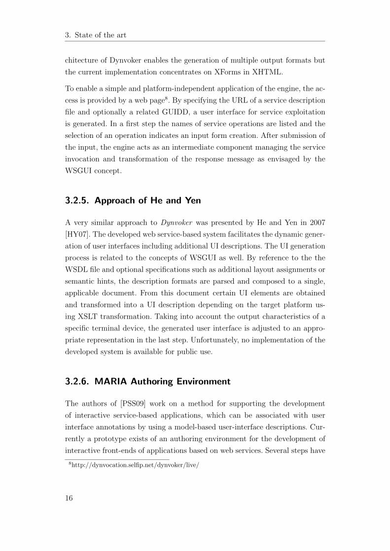
3.2.5. Approach of He and Yen
A very similar approach to Dynvoker was presented by He and Yen in 2007
[HY07]. The developed web service-based system facilitates the dynamic gener-
ation of user interfaces including additional UI descriptions. The UI generation
process is related to the concepts of WSGUI as well. By reference to the the
WSDL file and optional specifications such as additional layout assignments or
semantic hints, the description formats are parsed and composed to a single,
applicable document. From this document certain UI elements are obtained
and transformed into a UI description depending on the target platform us-
ing XSLT transformation. Taking into account the output characteristics of a
specific terminal device, the generated user interface is adjusted to an appro-
priate representation in the last step. Unfortunately, no implementation of the
developed system is available for public use.
3.2.6. MARIA Authoring Environment
The authors of [PSS09] work on a method for supporting the development
of interactive service-based applications, which can be associated with user
interface annotations by using a model-based user-interface descriptions. Cur-
rently a prototype exists of an authoring environment for the development of
interactive front-ends of applications based on web services. Several steps have
8http://dynvocation.selfip.net/dynvoker/live/
16

3.2. State of the Art Analysis
to be taken during the development process. The first is a bottom-up step in
order to analyse and include web services providing functionalities useful for
the new application to develop. The composition of the user accesses to the
various services is done by Concur Task Trees (CTT)9, which is a notation for
task model specifications. The result is a hierarchical structured task model,
which includes system tasks associated with web services and their operations.
Subsequently, the task model thus obtained will be used to derive, through
a further top-down stage, a first draft of the user interface at a logical level,
which will then be refined into more concrete terms, until a final user interface
description is defined in a platform-dependent implementation language. The
used language for describing and refining the user-interface is Model-based de-
scription of Interactive Applications (MARIA), which allows to describe user-
interfaces on an abstract level, for platform-independ definitions, and on a
concrete level, to provide a platform-dependent but implementation-language-
independent description. The main feature of MARIA are a data model as
an abstract description of the underlying data model of the user interface, an
event model, which allows for specifying at different abstraction levels how the
user-interface is able to respond to events triggered by the user, continuously
updating of fields, and a dynamic set of user interface elements, which allows
to update parts of the UI on a single page.
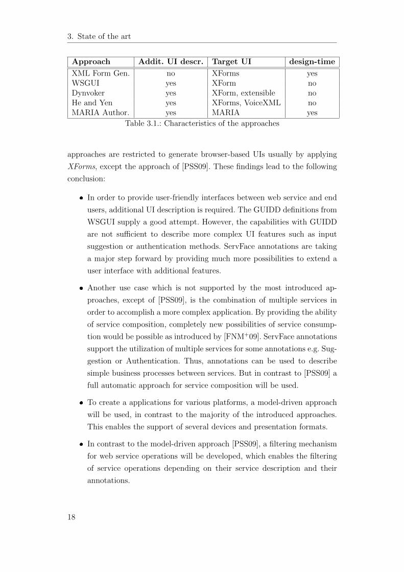
3.2.7. Conclusion
The presented approaches from the field of automatic generation of user in-
terfaces for web services show that several systems already exist by applying
different techniques. Table 3.1 provides a compact overview of the main char-
acteristics of the presented approaches.
The main distinctive feature of the different approaches is the inclusion of ad-
ditional user interface descriptions. As shown by reference to Dynvoker which
supports the generation of user interfaces with or without the inclusion of ad-
ditional UI descriptions, the use of this information can achieve a significantly
higher quality of the UI. Also the MARIA Authoring Environment supports
additional UI descriptions. Another peculiarity is that the most introduced
9http://giove.isti.cnr.it/tools/CTTE/CTTpublications/index.html
17
3. State of the art
Approach Addit. UI descr. Target UI design-time
XML Form Gen. no XForms yesWSGUI yes XForm noDynvoker yes XForm, extensible noHe and Yen yes XForms, VoiceXML noMARIA Author. yes MARIA yes
Table 3.1.: Characteristics of the approaches
approaches are restricted to generate browser-based UIs usually by applying
XForms, except the approach of [PSS09]. These findings lead to the following
conclusion:
� In order to provide user-friendly interfaces between web service and end
users, additional UI description is required. The GUIDD definitions from
WSGUI supply a good attempt. However, the capabilities with GUIDD
are not sufficient to describe more complex UI features such as input
suggestion or authentication methods. ServFace annotations are taking
a major step forward by providing much more possibilities to extend a
user interface with additional features.
� Another use case which is not supported by the most introduced ap-
proaches, except of [PSS09], is the combination of multiple services in
order to accomplish a more complex application. By providing the ability
of service composition, completely new possibilities of service consump-
tion would be possible as introduced by [FNM+09]. ServFace annotations
support the utilization of multiple services for some annotations e.g. Sug-
gestion or Authentication. Thus, annotations can be used to describe
simple business processes between services. But in contrast to [PSS09] a
full automatic approach for service composition will be used.
� To create a applications for various platforms, a model-driven approach
will be used, in contrast to the majority of the introduced approaches.
This enables the support of several devices and presentation formats.
� In contrast to the model-driven approach [PSS09], a filtering mechanism
for web service operations will be developed, which enables the filtering
of service operations depending on their service description and their
annotations.
18
4. Concept and Realization
In order to provide a solution for the problems raised by the requirements(2.2)
and by considering current developments around this topic (3), the following
sections explain the architecture and certain parts of the system in detail.
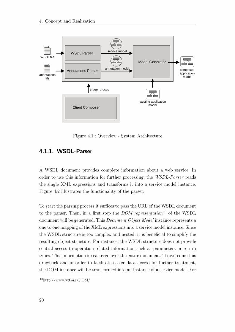
4.1. Architectural Concept
A system for automatic integration of user interfaces for annotated web ser-
vices into instances of a meta model for interactive service based applications is
required. For this purpose a Model-Generator, which creates parts of model in-
stances from the description of annotated web services and integrates them into
other instances, will be implemented. To process service descriptions, different
parsers have to be developed. Annotated web services are defined by a service
description file and an annotation file, already introduced in the fundamentals
section 3.1.1 of the State-of-the-Art chapter. The service description file and
the annotation file contain complete information for the description of detailed
user interfaces. In order to use this information for the generating process, the
WSDL-Parser and the Annotations-Parser transform the XML expressions
from the documents into instances of a meta-model expressing both, the ser-
vice data and the annotation data. In a next step the Model-Gernerator uses
this data for further processing. The whole process is triggered by the Client-
Composer. The system architecture is shown in figure 4.1. This partitioning
facilitates the development process and allows for fundamental changes, for ex-
ample the replacement of the WSDL-Parser in order to support an additional
version of the WSDL specification. Furthermore, this modularity of the genera-
tor fulfills the requirement /r8 (2.2) which demands a modular and changeable
system.
19
4. Concept and Realization
WSDL Parser
Annotations Parser
Model GeneratorWSDL file
annotationsfile
annotation model
service model
composedapplication
model
existing application model
Client Composer
trigger proces
Figure 4.1.: Overview - System Architecture
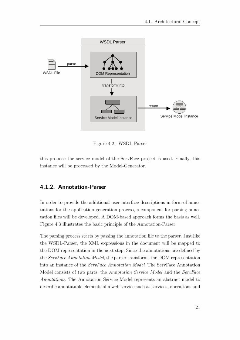
4.1.1. WSDL-Parser
A WSDL document provides complete information about a web service. In
order to use this information for further processing, the WSDL-Parser reads
the single XML expressions and transforms it into a service model instance.
Figure 4.2 illustrates the functionality of the parser.
To start the parsing process it suffices to pass the URL of the WSDL document
to the parser. Then, in a first step the DOM representation10 of the WSDL
document will be generated. This Document Object Model instance represents a
one to one mapping of the XML expressions into a service model instance. Since
the WSDL structure is too complex and nested, it is beneficial to simplify the
resulting object structure. For instance, the WSDL structure does not provide
central access to operation-related information such as parameters or return
types. This information is scattered over the entire document. To overcome this
drawback and in order to facilitate easier data access for further treatment,
the DOM instance will be transformed into an instance of a service model. For
10http://www.w3.org/DOM/
20
4.1. Architectural Concept
WSDL Parser
WSDL File
Service Model Instance
DOM Representation
parse
transform into
return
Service Model Instance
Figure 4.2.: WSDL-Parser
this propose the service model of the ServFace project is used. Finally, this
instance will be processed by the Model-Generator.
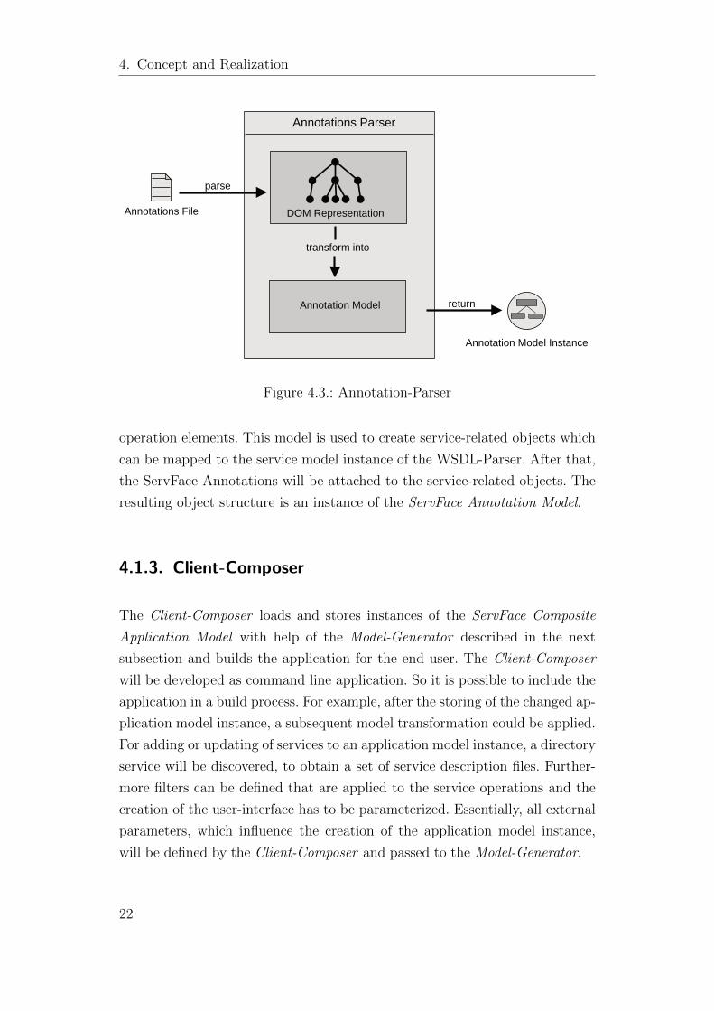
4.1.2. Annotation-Parser
In order to provide the additional user interface descriptions in form of anno-
tations for the application generation process, a component for parsing anno-
tation files will be developed. A DOM-based approach forms the basis as well.
Figure 4.3 illustrates the basic principle of the Annotation-Parser.
The parsing process starts by passing the annotation file to the parser. Just like
the WSDL-Parser, the XML expressions in the document will be mapped to
the DOM representation in the next step. Since the annotations are defined by
the ServFace Annotation Model, the parser transforms the DOM representation
into an instance of the ServFace Annotation Model. The ServFace Annotation
Model consists of two parts, the Annotation Service Model and the ServFace
Annotations. The Annotation Service Model represents an abstract model to
describe annotatable elements of a web service such as services, operations and
21
4. Concept and Realization
Annotations Parser
Annotations File DOM Representation
parse
return
Annotation Model Instance
Annotation Model
transform into
Figure 4.3.: Annotation-Parser
operation elements. This model is used to create service-related objects which
can be mapped to the service model instance of the WSDL-Parser. After that,
the ServFace Annotations will be attached to the service-related objects. The
resulting object structure is an instance of the ServFace Annotation Model.
4.1.3. Client-Composer
The Client-Composer loads and stores instances of the ServFace Composite
Application Model with help of the Model-Generator described in the next
subsection and builds the application for the end user. The Client-Composer
will be developed as command line application. So it is possible to include the
application in a build process. For example, after the storing of the changed ap-
plication model instance, a subsequent model transformation could be applied.
For adding or updating of services to an application model instance, a directory
service will be discovered, to obtain a set of service description files. Further-
more filters can be defined that are applied to the service operations and the
creation of the user-interface has to be parameterized. Essentially, all external
parameters, which influence the creation of the application model instance,
will be defined by the Client-Composer and passed to the Model-Generator.
22
4.1. Architectural Concept
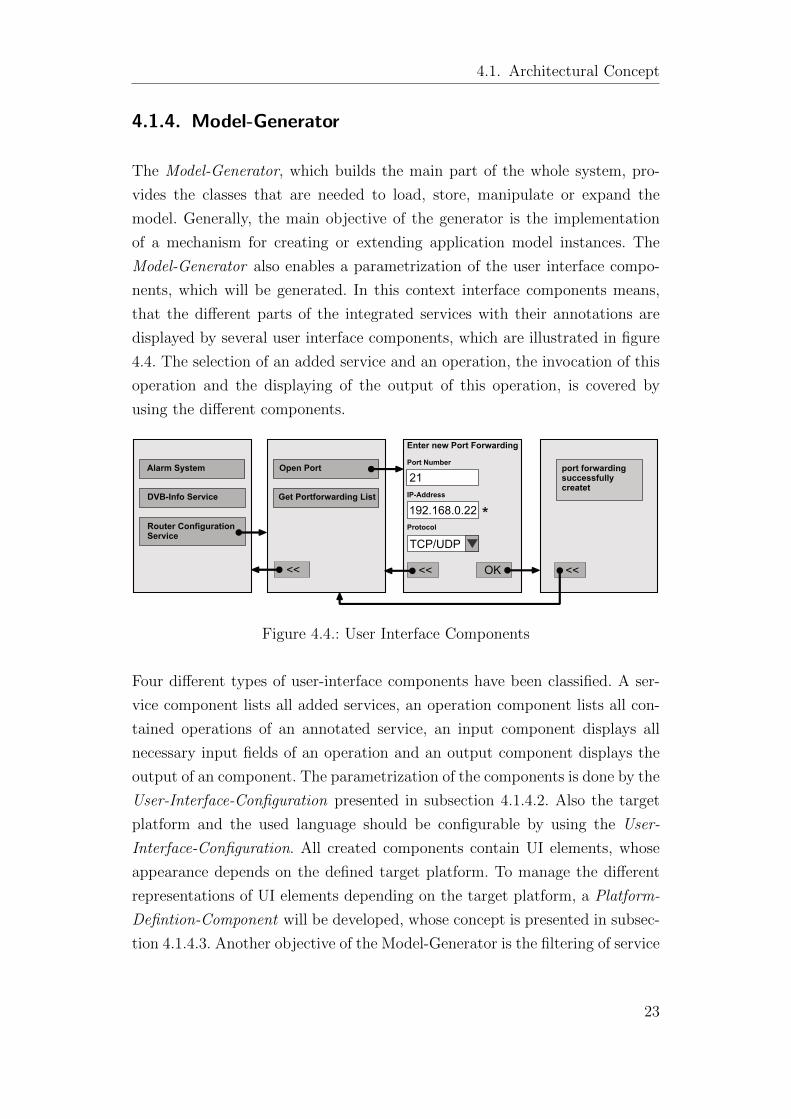
4.1.4. Model-Generator
The Model-Generator, which builds the main part of the whole system, pro-
vides the classes that are needed to load, store, manipulate or expand the
model. Generally, the main objective of the generator is the implementation
of a mechanism for creating or extending application model instances. The
Model-Generator also enables a parametrization of the user interface compo-
nents, which will be generated. In this context interface components means,
that the different parts of the integrated services with their annotations are
displayed by several user interface components, which are illustrated in figure
4.4. The selection of an added service and an operation, the invocation of this
operation and the displaying of the output of this operation, is covered by
using the different components.
Enter new Port Forwarding Port Number 45M4
IP-Address
Protocol*
TCP/UDP
21
192.168.0.22
OK<< <<
port forwardingsuccessfullycreatet
Alarm System
DVB-Info Service
Router ConfigurationService
Open Port
Get Portforwarding List
<<
Figure 4.4.: User Interface Components
Four different types of user-interface components have been classified. A ser-
vice component lists all added services, an operation component lists all con-
tained operations of an annotated service, an input component displays all
necessary input fields of an operation and an output component displays the
output of an component. The parametrization of the components is done by the
User-Interface-Configuration presented in subsection 4.1.4.2. Also the target
platform and the used language should be configurable by using the User-
Interface-Configuration. All created components contain UI elements, whose
appearance depends on the defined target platform. To manage the different
representations of UI elements depending on the target platform, a Platform-
Defintion-Component will be developed, whose concept is presented in subsec-
tion 4.1.4.3. Another objective of the Model-Generator is the filtering of service
23
4. Concept and Realization
operations on basis of a filter definition. The concept of this operation filter is
presented in subsection 4.1.4.1.
4.1.4.1. Operation-Filter
Operation filters used in the system are written in the Operation Filter Lan-
guage (OFL). Such an operation filter consist of several filer rules. A filter rule
can be
� an annotation rule, which can define annotations by qualified name.
� a parameter rule, which can define the parameter name, the parameter
type and the parameter type namespace.
� an operation name rule, which can define the operation name.
Every filter rule has a quantor, which can be Exist or his negation NotExist.
The filter rules are connected disjunctively in Disjunction-Rules which are
again conjunctively connected in Conjunction-Rules. Thus it is possible to
express all necessary combinations of definable filter rules. If an operation
fulfills one of the Conjunction-Rules, it will be filtered.
4.1.4.2. User-Interface-Configuration
Parameterization of the user interface elements is achieved by the use of the
User Interface Language (UIL). This language allows to define
� global parameters, which influence all user interface elements. Cur-
rently the global parameters consists of the target platform and the used
language.
� insertion parameters, which influence the insertion of new services
to the application model. The insertion parameters define the page, on
which the new elements are added.
� user interface components, which influences the components, that are
needed to list the services, to list their operations, to display the input
fields and to show the output of an operation.
24
4.2. Realization
If no configuration has been defined, a standard configuration will be used.
4.1.4.3. Platform-Definition-Component
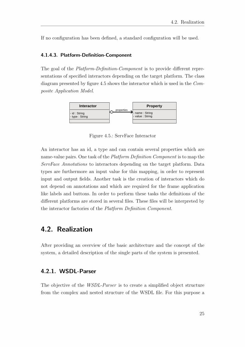
The goal of the Platform-Definition-Component is to provide different repre-
sentations of specified interactors depending on the target platform. The class
diagram presented by figure 4.5 shows the interactor which is used in the Com-
posite Application Model.
Property
- name : String- value : String
Interactor
- id : String- type : String
properties
Figure 4.5.: ServFace Interactor
An interactor has an id, a type and can contain several properties which are
name-value pairs. One task of the Platform Definition Component is to map the
ServFace Annotations to interactors depending on the target platform. Data
types are furthermore an input value for this mapping, in order to represent
input and output fields. Another task is the creation of interactors which do
not depend on annotations and which are required for the frame application
like labels and buttons. In order to perform these tasks the definitions of the
different platforms are stored in several files. These files will be interpreted by
the interactor factories of the Platform Definition Component.
4.2. Realization
After providing an overview of the basic architecture and the concept of the
system, a detailed description of the single parts of the system is presented.
4.2.1. WSDL-Parser
The objective of the WSDL-Parser is to create a simplified object structure
from the complex and nested structure of the WSDL file. For this purpose a
25
4. Concept and Realization
Service-Model has been created that describes necessary parts of the service.
The Service-Model is composed of simple service elements, thus the Builder-
Pattern which facilitates the construction of a composite object seems most
appropriate for the realization of the WSDL-Parser. Since the parser is devel-
oped in collaboration with the author of [Mar09], it has to fulfill requirements
of both approaches, thus the creation of different representations of a service
should be able to create. In [Mar09] a native model has been used for further
processing and in this context the ServFace Service Model has been used. With
the help of the Builder-Pattern, the abstract definition of construction steps
enables varying implementations and thus customized representations of the
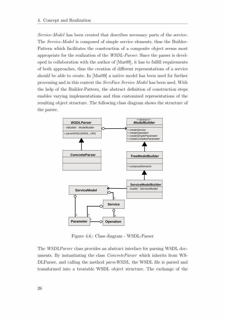
resulting object structure. The following class diagram shows the structure of
the parser.
WSDLParser - mBuilder : ModelBuilder + parseWSDL(WSDL_URI)
ModelBuilder + createService+ createOperation+ createSimpleParameter+ createComplexParameter
<<abstract>>
TreeModelBuilder
+ composeElements
ServiceModel
Parameter
Service
Operation
n
nn
nn
ServiceModelBuilder- model : ServiceModel
ConcreteParser
Figure 4.6.: Class diagram - WSDL-Parser
The WSDLParser class provides an abstract interface for parsing WSDL doc-
uments. By instantiating the class ConcreteParser which inherits from WS-
DLParser, and calling the method parseWSDL, the WSDL file is parsed and
transformed into a treatable WSDL object structure. The exchange of the
26
4.2. Realization
underlying library for processing the WSDL-documents becomes more easier
by implementing parseWSDL by ConcreteParser. The concrete instance of the
ServiceModelBuilder which is a child of the abstract TreeModelBuilder which is
again a child of the abstract ModelBuilder represents the builder. ModelBuilder
provides an abstract interface for creating representations of WSDL-documents
without structural restrictions. The abstract interface TreeModelBuilder re-
stricts the structure of the representation to a tree structured representation.
This implies that there is a head element which contains several child elements
which again can contain other child elements. The ServiceModelBuilder inher-
its from TreeModelBuilder and creates the concrete representation in form of
the ServFace Service Model. As shown by the class diagram, the ServiceModel
assigns a tree structure of the service elements Service, Operation and Param-
eter. That way, the complex object structure of the parsed WSDL file can be
adapted to the simple structure of the ServiceModel containing all necessary
information.
4.2.2. Annotation-Parser
As a complement to the basic concept, a detailed realization of the Annotation-
Parser has been designed. As already mentioned, the parser is based on the
ServFace Annotation Model and the main task is to create an object struc-
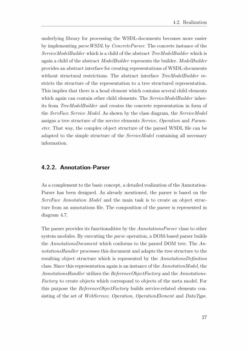
ture from an annotations file. The composition of the parser is represented in
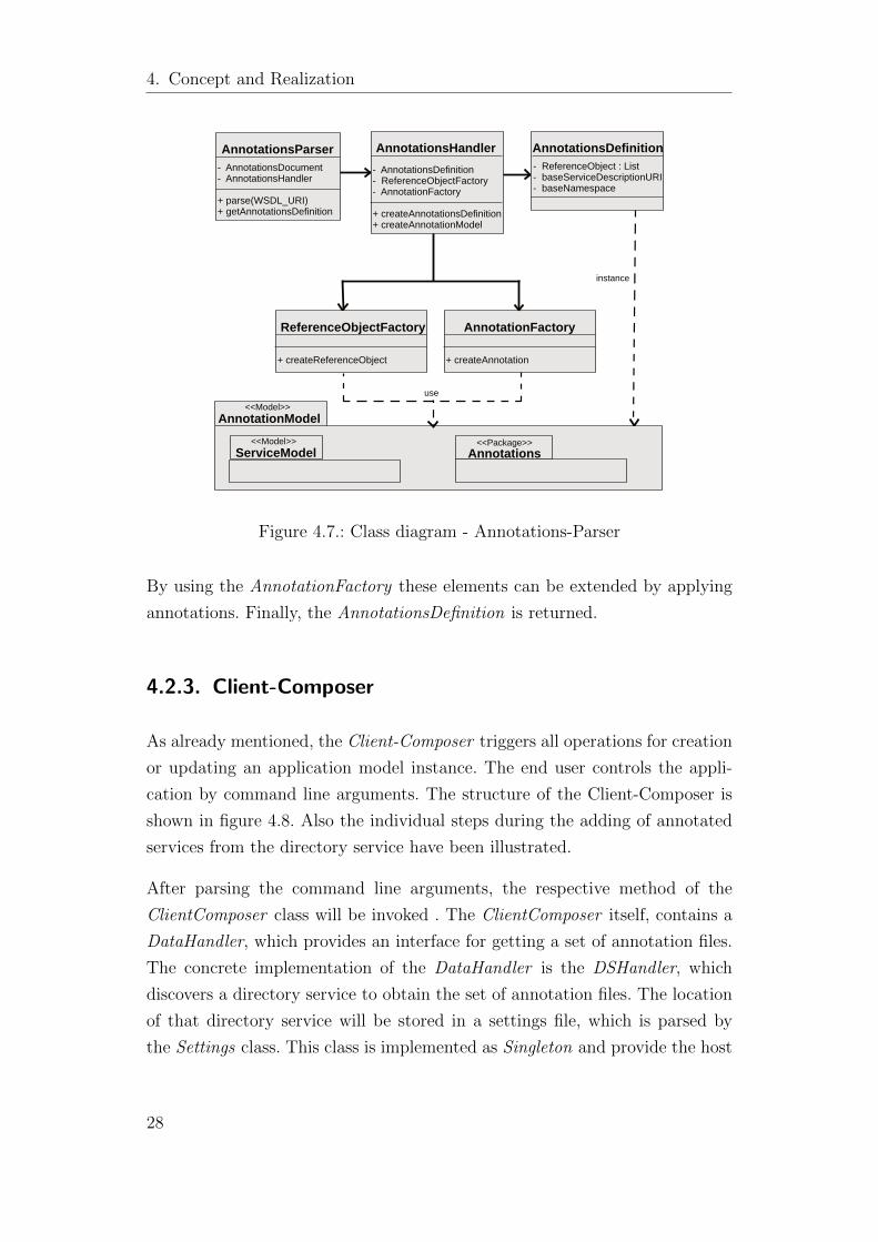
diagram 4.7.
The parser provides its functionalities by the AnnotationsParser class to other
system modules. By executing the parse operation, a DOM-based parser builds
the AnnotationsDocument which conforms to the parsed DOM tree. The An-
notationsHandler processes this document and adapts the tree structure to the
resulting object structure which is represented by the AnnotationsDefinition
class. Since this representation again is an instance of the AnnotationModel, the
AnnotationsHandler utilizes the ReferenceObjectFactory and the Annotations-
Factory to create objects which correspond to objects of the meta model. For
this purpose the ReferenceObjectFactory builds service-related elements con-
sisting of the set of WebService, Operation, OperationElement and DataType.
27
4. Concept and Realization
AnnotationsParser - AnnotationsDocument- AnnotationsHandler
+ parse(WSDL_URI)+ getAnnotationsDefinition
AnnotationsHandler- AnnotationsDefinition- ReferenceObjectFactory- AnnotationFactory
+ createAnnotationsDefinition+ createAnnotationModel
ReferenceObjectFactory + createReferenceObject
AnnotationFactory + createAnnotation
AnnotationsDefinition - ReferenceObject : List- baseServiceDescriptionURI- baseNamespace
AnnotationModel<<Model>>
ServiceModel Annotations<<Model>> <<Package>>
instance
use
Figure 4.7.: Class diagram - Annotations-Parser
By using the AnnotationFactory these elements can be extended by applying
annotations. Finally, the AnnotationsDefinition is returned.
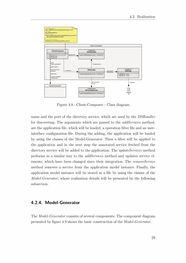
4.2.3. Client-Composer
As already mentioned, the Client-Composer triggers all operations for creation
or updating an application model instance. The end user controls the appli-
cation by command line arguments. The structure of the Client-Composer is
shown in figure 4.8. Also the individual steps during the adding of annotated
services from the directory service have been illustrated.
After parsing the command line arguments, the respective method of the
ClientComposer class will be invoked . The ClientComposer itself, contains a
DataHandler, which provides an interface for getting a set of annotation files.
The concrete implementation of the DataHandler is the DSHandler, which
discovers a directory service to obtain the set of annotation files. The location
of that directory service will be stored in a settings file, which is parsed by
the Settings class. This class is implemented as Singleton and provide the host
28
4.2. Realization
Client-Composer
ClientComposer
+ addServices+ updateServices+ removeService
<<interface>>DataHandler
+ getAnnotatedWebservices() : List<String>dataHandler
DSHandler
+ getAnnotatedWebservices() : List<String>
<<implements>>
<<creates>><<singleton>>Settings
+ getDSHost+ getDSPort
: String : String
get serviceparameters
settingsfile
<<parse>>
<<webservice>>DirectoryService
+ getAnnotatedWebservices() : List<String>
get annotationuri set
Model-Generator
load / create application
add services
remove serviceelement
apply filter
set user-interfaceconfiguration
//load applicationapp = CAMGenerator.loadApplication(appUri, uic);//set filterapp.setFilter(filterUri);//add servicesforeach (dataHandler.getAnnotatedWebservices as aS) { app.addAnnotatedService(aS);}//save model instanceModelUtils.saveToFile(app.getCAM, appUri);
Figure 4.8.: Client-Composer - Class diagram
name and the port of the directory service, which are used by the DSHandler
for discovering. The arguments which are passed to the addServices method,
are the application file, which will be loaded, a operation filter file and an user-
interface configuration file. During the adding, the application will be loaded
by using the classes of the Model-Generator. Then a filter will be applied to
the application and in the next step the annotated service fetched from the
directory service will be added to the application. The updateServices method
performs in a similar way to the addServices method and updates service el-
ements, which have been changed since their integration. The removeService
method removes a service from the application model instance. Finally, the
application model instance will be stored in a file by using the classes of the
Model-Generator, whose realization details will be presented by the following
subsection.
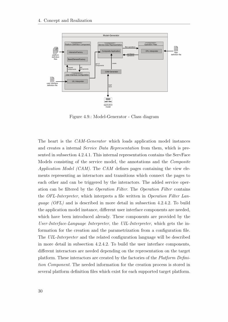
4.2.4. Model-Generator
The Model-Generator consists of several components. The component diagram
presented by figure 4.9 shows the basic construction of the Model-Generator.
29
4. Concept and Realization
Model-Generator
Platform Definition Component<<component>>
InteractorFactory
BasicElementFactory
Operation Filter<<component>>
OFL Interpreter
User Interface Configuration<<component>>
UIL Interpreter
Service Data Representation<<component>>
Composite Application
filter operations
CAM Generator
create
platformdefinition
files
filterdefinition file
user interfacedefinition file
get filteredoperations
requestcomponents
getcomponents
get UIcomponents
application model
load/save
Figure 4.9.: Model-Generator - Class diagram
The heart is the CAM-Generator which loads application model instances
and creates a internal Service Data Representation from them, which is pre-
sented in subsection 4.2.4.1. This internal representation contains the ServFace
Models consisting of the service model, the annotations and the Composite
Application Model (CAM). The CAM defines pages containing the view ele-
ments representing as interactors and transitions which connect the pages to
each other and can be triggered by the interactors. The added service oper-
ation can be filtered by the Operation Filter. The Operation Filter contains
the OFL-Interpreter, which interprets a file written in Operation Filter Lan-
guage (OFL) and is described in more detail in subsection 4.2.4.2. To build
the application model instance, different user interface components are needed,
which have been introduced already. These components are provided by the
User-Interface-Language Interpreter, the UIL-Interpreter, which gets the in-
formation for the creation and the parametrization from a configuration file.
The UIL-Interpreter and the related configuration language will be described
in more detail in subsection 4.2.4.2. To build the user interface components,
different interactors are needed depending on the representation on the target
platform. These interactors are created by the factories of the Platform Defini-
tion Component. The needed information for the creation process is stored in
several platform definition files which exist for each supported target platform.
30
4.2. Realization
The realization details of Platform Definition Component is described in more
detail in subsection 4.2.4.3 on page 40.
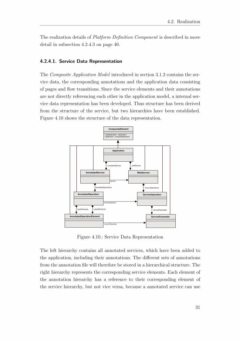
4.2.4.1. Service Data Representation
The Composite Application Model introduced in section 3.1.2 contains the ser-
vice data, the corresponding annotations and the application data consisting
of pages and flow transitions. Since the service elements and their annotations
are not directly referencing each other in the application model, a internal ser-
vice data representation has been developed. Thus structure has been derived
from the structure of the service, but two hierarchies have been established.
Figure 4.10 shows the structure of the data representation.
inputElements outputElements
AnnotatedOperationElement
AnnotatedOperation
annotatedOperations
AnnotatedService
annotatedSerives
CompositeElement
+ getApplication : Application+ getParent : CompositeElement
Application
WebService
ServiceOperation
ServiceParameter
webSerives
serviceOperations
serviceParameter
serviceParameter
serviceOperation
service
Figure 4.10.: Service Data Representation
The left hierarchy contains all annotated services, which have been added to
the application, including their annotations. The different sets of annotations
from the annotation file will therefore be stored in a hierarchical structure. The
right hierarchy represents the corresponding service elements. Each element of
the annotation hierarchy has a reference to their corresponding element of
the service hierarchy, but not vice versa, because a annotated service can use
31
4. Concept and Realization
operations from a other service, which can be again annotated in an other
service, e.g. the login operation of an authentication service. This structure
is also well suitable for further processing. The connection of the annotation
and their service object makes the filter mechanism more easy, because all
needed informations can be accessed through one object. The filter mechanism
is described in detail in the following subsection. Also the creating of the user
interface components becomes more easy, because each parent object on the
left hierarchy represents a component displaying their children elements. The
creation of the user interface components is described in detail in the UIL-
Interpreter paragraph of the next subsection 4.2.4.2.
4.2.4.2. Domain Specific Languages OFL and UIL
In order to provide the functionality for filtering of service operations and in
order to make these filters configurable, a domain specific language (DSL) has
been developed. Such a filter will be written in Operations Filter Language
(OFL). In order to provide the functionality for parametrization of user inter-
face components another domain specific language called User Interface Lan-
guage (UIL) has been developed. Both DSLs are defined in Extended Backus-
Naur Form11 in textual form. The following two figures shows the syntax di-
agrams of the derived languages. Figure 4.11 on page 33 shows the syntax
diagram of OFL and figure 4.13 on page 36 shows the syntax diagram of UIL.
To interpret these two languages, two interpreters have been developed, the
OFL-Interpreter and the UIL-Interpreter, which will also be presented in the
following paragraphs.
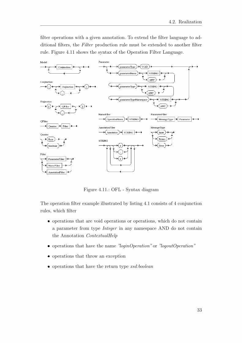
Operation Filter Language (OFL) An operation filter consists of several fil-
ter rules which can be a ParameterFilter, a NameFilter or an AnnotationFilter.
A ParameterFilter is able to describe the operation parameters which should
be filtered by defining the type names and their type namespaces. With the
NameFilter it is possible to filter Operations with a defined name. The An-
notationFilter can define annotations by qualified name, thus it is possible to
11EBNF is a metasyntax notation used to express context-free grammars and adopted as ISO-Standard ISO-14977http://standards.iso.org/ittf/PubliclyAvailableStandards/s026153 ISO IEC 14977 1996(E).zip
32
4.2. Realization
filter operations with a given annotation. To extend the filter language to ad-
ditional filters, the Filter production rule must be extended to another filter
rule. Figure 4.11 shows the syntax of the Operation Filter Language.
Figure 4.11.: OFL - Syntax diagram
The operation filter example illustrated by listing 4.1 consists of 4 conjunction
rules, which filter
� operations that are void operations or operations, which do not contain
a parameter from type Integer in any namespace AND do not contain
the Annotation ContextualHelp
� operations that have the name ”loginOperation” or ”logoutOperation”
� operations that throw an exception
� operations that have the return type xsd:boolean
33
4. Concept and Realization
1 {
2 [ Exist Input parameterType VOID,
3 NotExist Input parameterName ANY parameterType "Integer" parameterTypeNamespace ANY],
4
5 [ NotExist Annotation "servfaceannotationmodel.annotations.ContextualHelp" ]
6 }
7 {
8 [ Exist OperationName "loginOperation", Exist OperationName "logoutOperation" ]
9 }
10 {
11 [ Exist Error parameterName ANY parameterType ANY parameterTypeNamespace ANY ]
12 }
13 {
14 [ Exist Return parameterName ANY parameterType "boolean" parameterTypeNamespace "http://www
.w3.org/2001/XMLSchema" ]
15 }
Listing 4.1: OFL - Example
The structure of the OFL-Interpreter which interprets this language is also di-
rectly derived from this grammar. It will be described in the next paragraph.
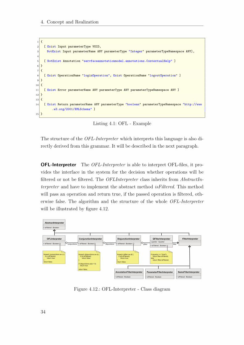
OFL-Interpreter The OFL-Interpreter is able to interpret OFL-files, it pro-
vides the interface in the system for the decision whether operations will be
filtered or not be filtered. The OFLInterpreter class inherits from AbstractIn-
terpreter and have to implement the abstract method isFiltered. This method
will pass an operation and return true, if the passed operation is filtered, oth-
erwise false. The algorithm and the structure of the whole OFL-Interpreter
will be illustrated by figure 4.12.
AbstractInterpreter
+ isFiltered : Boolean
OFLInterpreter
+ isFiltered : Boolean
ConjunctionInterpreter
+ isFiltered : Boolean
DisjunctionInterpreter
+ isFiltered : Boolean
QFilterInterpreter- quantor : Quantor
+ isFiltered : Boolean
FilterInterpreter
NameFilterInterpreter
+ isFiltered : Boolean
ParameterFilterInterpreter
+ isFiltered : Boolean
AnnotationFilterInterpreter
+ isFiltered : Boolean
conjunctions disjunctions qfilter filter
+
foreach (conjunctions as c) { if (c.isFiltered) return true;}return false;
foreach (disjunctions as d) { if (!d.isFiltered) return false;}
if (disjunctions.size > 0) return true;
return false;
foreach (qfilter as qf) { if (qf.isFiltered) return true;}return false;
if (quantor == “Exist”) return filter.isFiltered;else return !filter.isFiltered;
Figure 4.12.: OFL-Interpreter - Class diagram
34
4.2. Realization
The OFLInterpreter class interprets the OFL-file and instantiates a Conjunc-
tionInterpreter for each defined Conjunction-Rule. If one of these rules is ful-
filled, the operation is filtered. The ConjunctionInterpreter instantiates for
each nested Disjunction-Rule a DisjunctionInterpreter. An operation is then
filtered, if all Disjunction-Rules are fulfilled. The DisjunctionInterpreter in-
stantiate for each nested QFilter-Rule a QFilterInterpreter. A QFilter-Rule is
an operation filter rule with a quantifier specified. If one of these QFilter-Rules
is fulfilled, the operation is filtered. The QFilterInterpreter instantiates the in-
terpreter which interprets the real operation filter. All these interpreters inherit
from the abstract class FilterInterpreter. That makes it possible to extend the
OFL-Interpreter to another filter interpreter, if the Operation Filter Language
is extended to another operation filter. The method isFiltered of the inherited
classes interpret the real filter rules.
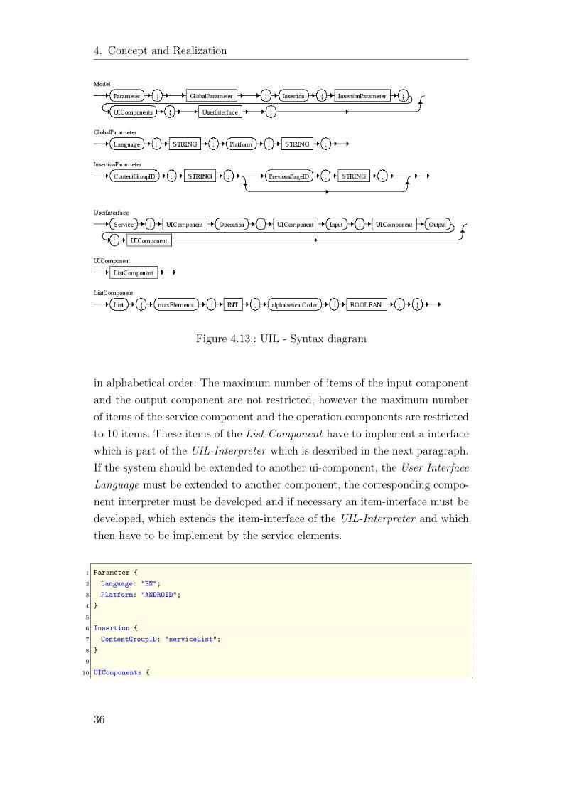
User Interface Language (UIL) A UIL-file is divided into three sections.
The global parameter part marked by Parameter defines the target language
and target platform. The insertion part marked by Insertion defines the group,
which will be replaced by the service component that contains the user interface
elements representing the services. The third section defines the user interface
components and their parameters. Currently four different components can be
described, which have the type List. The first component is responsible for
listing the services, the second component for listing the service operations,
the third component for listing the input fields and the 4th component for
showing the output of an executed operation. Figure 4.13 shows the syntax of
the User Interface Language.
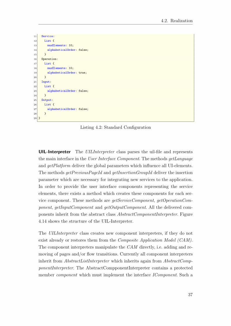
Currently there is one concrete user interface component defined by the User
Interface Language which is from type List. In this context type List means
that the contained ui-elements take their own page and are displayed in a
ordered or not ordered list depending on the definition in the uil-file. If no con-
figuration is defined by the user, the standard configuration is loaded which is
shown in listing 4.2. In this configuration the language is set to English and
the target platform is Android. The elements representing the added services,
will be inserted in the content group with the id seviceList. All components
are from type List and the services and operations names will be displayed
35
4. Concept and Realization
Figure 4.13.: UIL - Syntax diagram
in alphabetical order. The maximum number of items of the input component
and the output component are not restricted, however the maximum number
of items of the service component and the operation components are restricted
to 10 items. These items of the List-Component have to implement a interface
which is part of the UIL-Interpreter which is described in the next paragraph.
If the system should be extended to another ui-component, the User Interface
Language must be extended to another component, the corresponding compo-
nent interpreter must be developed and if necessary an item-interface must be
developed, which extends the item-interface of the UIL-Interpreter and which
then have to be implement by the service elements.
1 Parameter {
2 Language: "EN";
3 Platform: "ANDROID";
4 }
5
6 Insertion {
7 ContentGroupID: "serviceList";
8 }
9
10 UIComponents {
36
4.2. Realization
11 Service:
12 List {
13 maxElements: 10;
14 alphabeticalOrder: false;
15 }
16 Operation:
17 List {
18 maxElements: 10;
19 alphabeticalOrder: true;
20 }
21 Input:
22 List {
23 alphabeticalOrder: false;
24 }
25 Output:
26 List {
27 alphabeticalOrder: false;
28 }
29 }
Listing 4.2: Standard Configuration
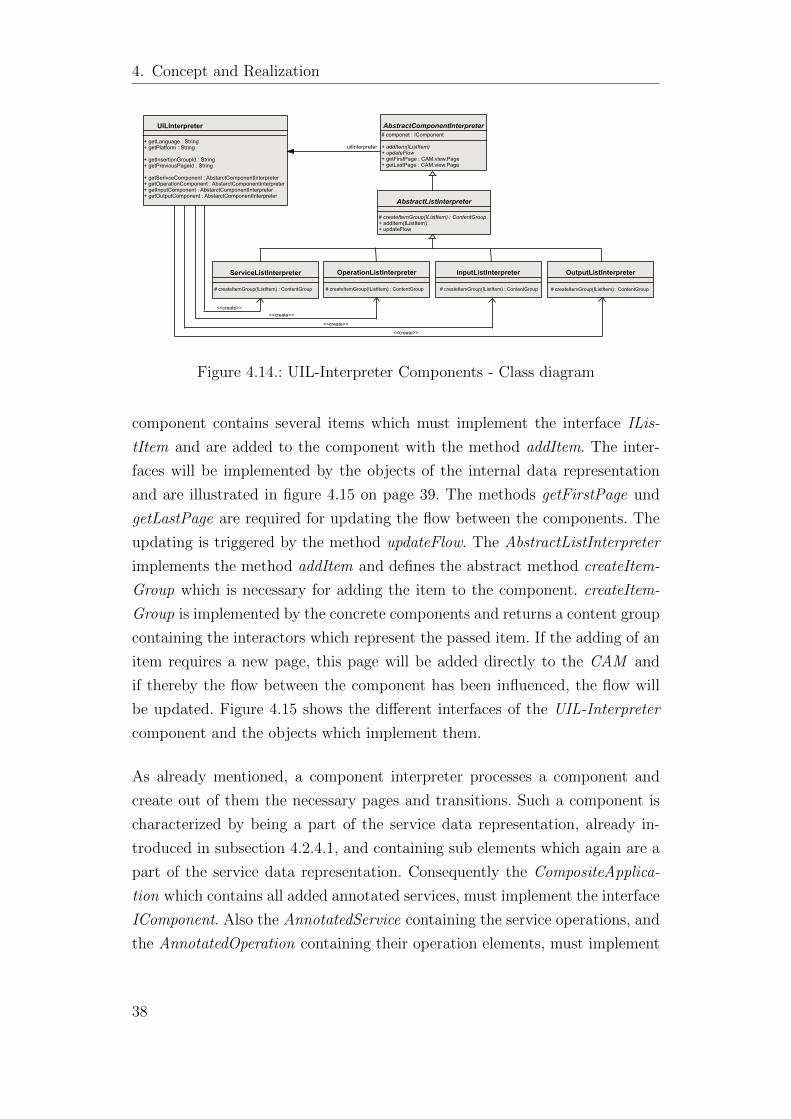
UIL-Interpreter The UILInterpreter class parses the uil-file and represents
the main interface in the User Interface Component. The methods getLanguage
and getPlatform deliver the global parameters which influence all UI-elements.
The methods getPreviousPageId and getInsertionGroupId deliver the insertion
parameter which are necessary for integrating new services to the application.
In order to provide the user interface components representing the service
elements, there exists a method which creates these components for each ser-
vice component. These methods are getServiceComponent, getOperationCom-
ponent, getInputComponent and getOutputComponent. All the delivered com-
ponents inherit from the abstract class AbstractComponentInterpreter. Figure
4.14 shows the structure of the UIL-Interpreter.
The UILInterpreter class creates new component interpreters, if they do not
exist already or restores them from the Composite Application Model (CAM).
The component interpreters manipulate the CAM directly, i.e. adding and re-
moving of pages and/or flow transitions. Currently all component interpreters
inherit from AbstractListInterpreter which inherits again from AbstractComp-
ponentInterpreter. The AbstractCompponentInterpreter contains a protected
member component which must implement the interface IComponent. Such a
37
4. Concept and Realization
UILInterpreter
+ getLanguage : String+ getPlatform : String
+ getInsertionGroupId : String+ getPreviousPageId : String
+ getSerivceComponent : AbstarctComponentInterpreter+ getOperationComponent : AbstarctComponentInterpreter+ getInputComponent : AbstarctComponentInterpreter+ getOutputComponent : AbstarctComponentInterpreter
AbstractComponentInterpreter# componet : IComponent + addItem(IListItem)+ updateFlow+ getFirstPage : CAM.view.Page+ getLastPage : CAM.view.Page
AbstractListInterpreter
# createItemGroup(IListItem) : ContentGroup+ addItem(IListItem)+ updateFlow
ServiceListInterpreter
# createItemGroup(IListItem) : ContentGroup
OperationListInterpreter
# createItemGroup(IListItem) : ContentGroup
InputListInterpreter
# createItemGroup(IListItem) : ContentGroup
OutputListInterpreter
# createItemGroup(IListItem) : ContentGroup
<<create>><<create>>
<<create>>
<<create>>
uilInterpreter
Figure 4.14.: UIL-Interpreter Components - Class diagram
component contains several items which must implement the interface ILis-
tItem and are added to the component with the method addItem. The inter-
faces will be implemented by the objects of the internal data representation
and are illustrated in figure 4.15 on page 39. The methods getFirstPage und
getLastPage are required for updating the flow between the components. The
updating is triggered by the method updateFlow. The AbstractListInterpreter
implements the method addItem and defines the abstract method createItem-
Group which is necessary for adding the item to the component. createItem-
Group is implemented by the concrete components and returns a content group
containing the interactors which represent the passed item. If the adding of an
item requires a new page, this page will be added directly to the CAM and
if thereby the flow between the component has been influenced, the flow will
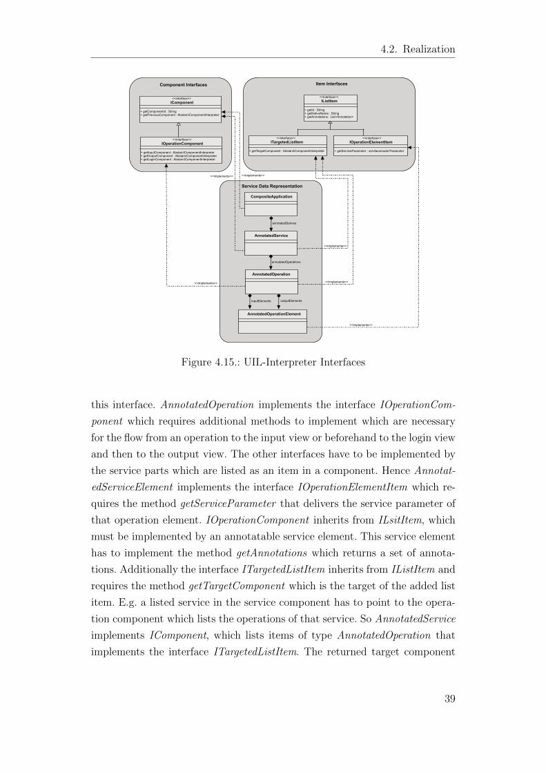
be updated. Figure 4.15 shows the different interfaces of the UIL-Interpreter
component and the objects which implement them.
As already mentioned, a component interpreter processes a component and
create out of them the necessary pages and transitions. Such a component is
characterized by being a part of the service data representation, already in-
troduced in subsection 4.2.4.1, and containing sub elements which again are a
part of the service data representation. Consequently the CompositeApplica-
tion which contains all added annotated services, must implement the interface
IComponent. Also the AnnotatedService containing the service operations, and
the AnnotatedOperation containing their operation elements, must implement
38
4.2. Realization
Component Interfaces Item Interfaces
Service Data Representation
IListItem
+ getId : String+ getNativeName : String+ getAnnotations : List<Annotation>
<<interface>>
ITargetedListItem
+ getTargetComponent : AbstarctComponentInterpreter
<<interface>>IOperationElementItem
+ getServiceParameter : servfacemodel.Parameter
<<interface>>
IComponent
+ getComponentId : String+ getPreviousComponent : AbstarctComponentInterpreter
<<interface>>
IOperationComponent
+ getInputComponent : AbstarctComponentInterpreter+ getOutputComponent : AbstarctComponentInterpreter+ getLoginComponent : AbstarctComponentInterpreter
<<interface>>
<<implements>>
<<implements>>
<<implements>>
<<implements>><<implements>>
<<implements>>
AnnotatedOperationElement
AnnotatedOperation
AnnotatedService
CompositeApplication
inputElements outputElements
annotatedOperations
annotatedSerives
Figure 4.15.: UIL-Interpreter Interfaces
this interface. AnnotatedOperation implements the interface IOperationCom-
ponent which requires additional methods to implement which are necessary
for the flow from an operation to the input view or beforehand to the login view
and then to the output view. The other interfaces have to be implemented by
the service parts which are listed as an item in a component. Hence Annotat-
edServiceElement implements the interface IOperationElementItem which re-
quires the method getServiceParameter that delivers the service parameter of
that operation element. IOperationComponent inherits from ILsitItem, which
must be implemented by an annotatable service element. This service element
has to implement the method getAnnotations which returns a set of annota-
tions. Additionally the interface ITargetedListItem inherits from IListItem and
requires the method getTargetComponent which is the target of the added list
item. E.g. a listed service in the service component has to point to the opera-
tion component which lists the operations of that service. So AnnotatedService
implements IComponent, which lists items of type AnnotatedOperation that
implements the interface ITargetedListItem. The returned target component
39
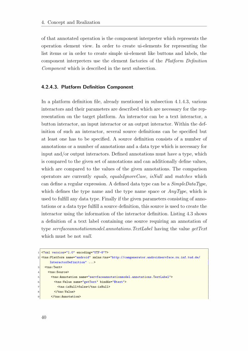
4. Concept and Realization
of that annotated operation is the component interpreter which represents the
operation element view. In order to create ui-elements for representing the
list items or in order to create simple ui-element like buttons and labels, the
component interpreters use the element factories of the Platform Definition
Component which is described in the next subsection.
4.2.4.3. Platform Definition Component
In a platform definition file, already mentioned in subsection 4.1.4.3, various
interactors and their parameters are described which are necessary for the rep-
resentation on the target platform. An interactor can be a text interactor, a
button interactor, an input interactor or an output interactor. Within the def-
inition of such an interactor, several source definitions can be specified but
at least one has to be specified. A source definition consists of a number of
annotations or a number of annotations and a data type which is necessary for
input and/or output interactors. Defined annotations must have a type, which
is compared to the given set of annotations and can additionally define values,
which are compared to the values of the given annotations. The comparison
operators are currently equals, equalsIgnoreCase, isNull and matches which
can define a regular expression. A defined data type can be a SimpleDataType,
which defines the type name and the type name space or AnyType, which is
used to fulfill any data type. Finally if the given parameters consisting of anno-
tations or a data type fulfill a source definition, this source is used to create the
interactor using the information of the interactor definition. Listing 4.3 shows
a definition of a text label containing one source requiring an annotation of
type servfaceannotationmodel.annotations.TextLabel having the value getText
which must be not null.
1 <?xml version="1.0" encoding="UTF-8"?>
2 <tns:Platform name="android" xmlns:tns="http://camgenerator.androidservface.rn.inf.tud.de/
InteractorDefinition" ...>
3 <tns:Text>
4 <tns:Source>
5 <tns:Annotation name="servfaceannotationmodel.annotations.TextLabel">
6 <tns:Value name="getText" bindAs="$text">
7 <tns:isNull>false</tns:isNull>
8 </tns:Value>
9 </tns:Annotation>
40
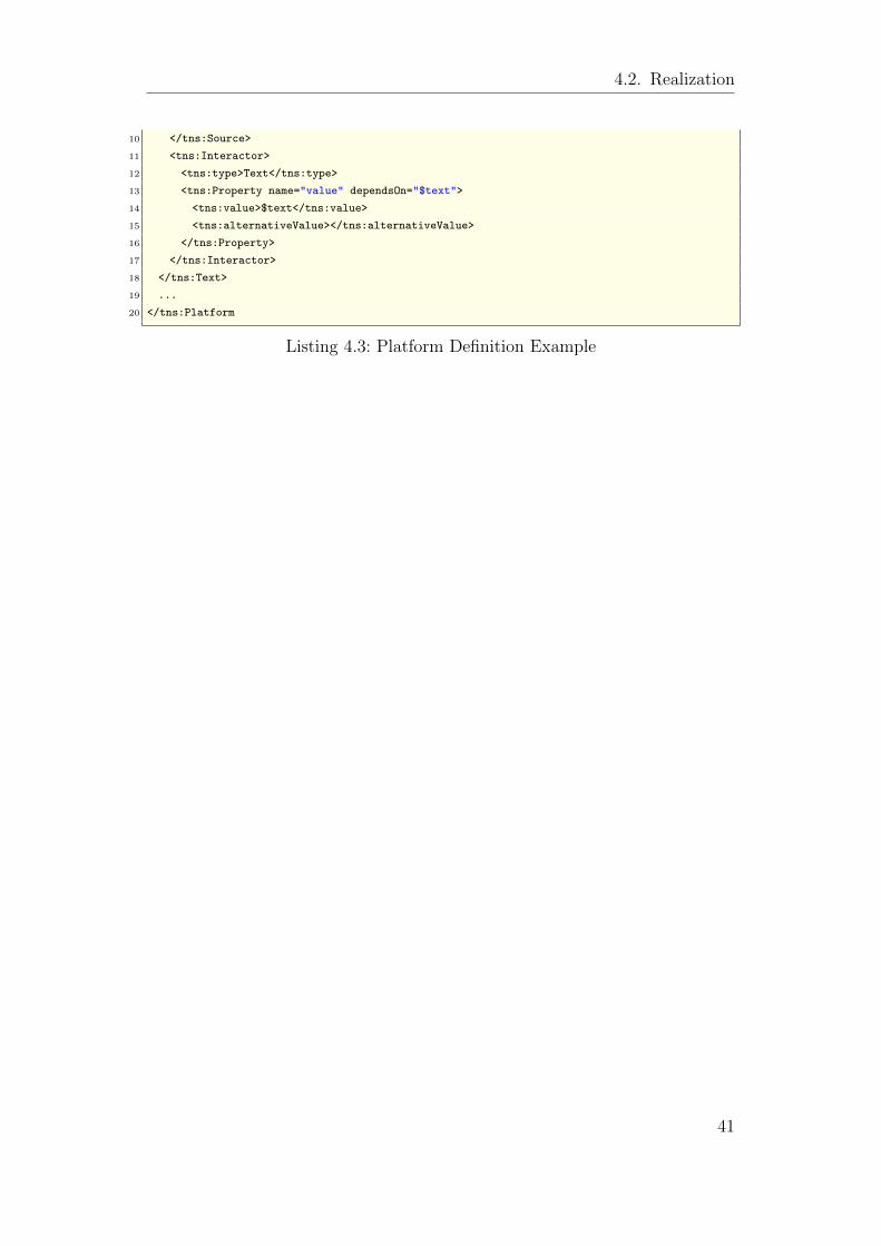
4.2. Realization
10 </tns:Source>
11 <tns:Interactor>
12 <tns:type>Text</tns:type>
13 <tns:Property name="value" dependsOn="$text">
14 <tns:value>$text</tns:value>
15 <tns:alternativeValue></tns:alternativeValue>
16 </tns:Property>
17 </tns:Interactor>
18 </tns:Text>
19 ...
20 </tns:Platform
Listing 4.3: Platform Definition Example
41
5. Implementation
5. Implementation
The implementation of the conceptualized generator includes the implementa-
tion of a dynamic service infrastructure to build an appropriate test environ-
ment. For this purpose the use case services from chapter Analyses (2.1) will
be adapted. The following sections expound the major implementation issues
that occurred during the implementation of the services and the generator.
The steps of implementation will be illustrated by code examples referred to
the Alarm System service.
5.1. Web Services
For the implementation of the web services Eclipse Galileo (3.5.1) was chosen
as IDE. The additional Eclipse extension Web Tools Platform(WTP) contains
tools and APIs to support deploying, running, and testing web applications.
The integrated Apache Axis 2 Version 1.4.1 was used for the deployment of
the web services on an Apache Tomcat Server 6.0.20.
The three services DVB Television, Alarm System and Router Configuration
have been implemented with the functionalities shown by the use case diagrams
of chapter Analyses(2.1). In order to simulate the functionalities the service
operations have been realized provisionally. Since the services Alarm System
and Router Configuration require for authentication treatment, a further Au-
thentication Service has been realized for this purpose. This Authentication
Service provides methods for login, logout and session validation checking. To
use the authentication methods, the Router Configuration and Alarm System
service were build as service clients of the Authentication Service. This way,
the Apache Axis 2 engine generates service stubs to provide access to opera-
tions of the Authentication Service. Listing 5.1 demonstrates the utilization of
the authentication within the Alarm System Service.
42
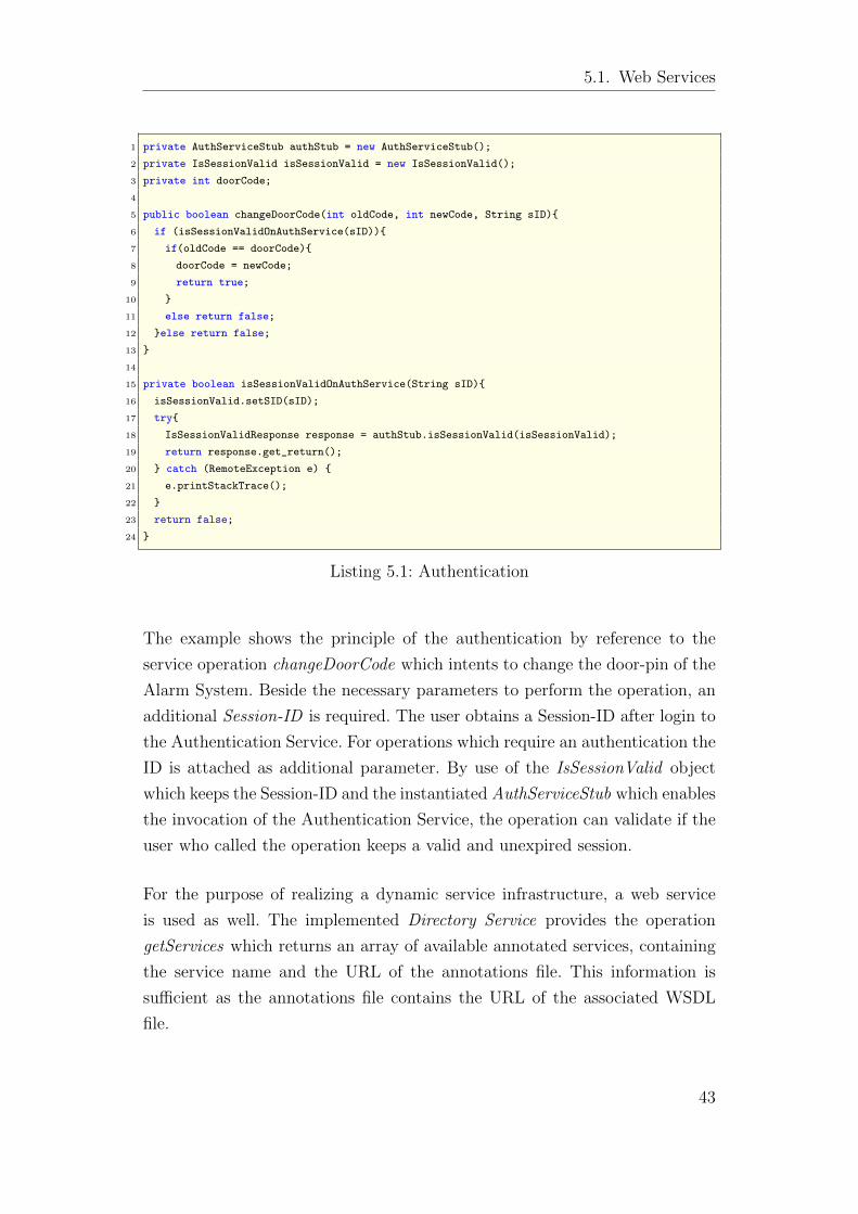
5.1. Web Services
1 private AuthServiceStub authStub = new AuthServiceStub();
2 private IsSessionValid isSessionValid = new IsSessionValid();
3 private int doorCode;
4
5 public boolean changeDoorCode(int oldCode, int newCode, String sID){
6 if (isSessionValidOnAuthService(sID)){
7 if(oldCode == doorCode){
8 doorCode = newCode;
9 return true;
10 }
11 else return false;
12 }else return false;
13 }
14
15 private boolean isSessionValidOnAuthService(String sID){
16 isSessionValid.setSID(sID);
17 try{
18 IsSessionValidResponse response = authStub.isSessionValid(isSessionValid);
19 return response.get_return();
20 } catch (RemoteException e) {
21 e.printStackTrace();
22 }
23 return false;
24 }
Listing 5.1: Authentication
The example shows the principle of the authentication by reference to the
service operation changeDoorCode which intents to change the door-pin of the
Alarm System. Beside the necessary parameters to perform the operation, an
additional Session-ID is required. The user obtains a Session-ID after login to
the Authentication Service. For operations which require an authentication the
ID is attached as additional parameter. By use of the IsSessionValid object
which keeps the Session-ID and the instantiated AuthServiceStub which enables
the invocation of the Authentication Service, the operation can validate if the
user who called the operation keeps a valid and unexpired session.
For the purpose of realizing a dynamic service infrastructure, a web service
is used as well. The implemented Directory Service provides the operation
getServices which returns an array of available annotated services, containing
the service name and the URL of the annotations file. This information is
sufficient as the annotations file contains the URL of the associated WSDL
file.
43
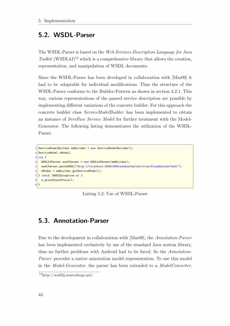
5. Implementation
5.2. WSDL-Parser
The WSDL-Parser is based on the Web Services Description Language for Java
Toolkit (WSDL4J)12 which is a comprehensive library that allows the creation,
representation, and manipulation of WSDL documents.
Since the WSDL-Parser has been developed in collaboration with [Mar09] it
had to be adaptable for individual modifications. Thus the structure of the
WSDL-Parser conforms to the Builder-Pattern as shown in section 4.2.1. This
way, various representations of the parsed service description are possible by
implementing different variations of the concrete builder. For this approach the
concrete builder class ServiceModelBuilder has been implemented to obtain
an instance of ServFace Service Model for further treatment with the Model-
Generator. The following listing demonstrates the utilization of the WSDL-
Parser.
1 ServiceModelBuilder smBuilder = new ServiceModelBuilder();
2 ServiceModel sModel;
3 try {
4 WSDL4JParser wsdlParser = new WSDL4JParser(smBuilder);
5 wsdlParser.parseWSDL("http://localhost:8080/WSAlarmSystem/services/AlarmSystem?wsdl");
6 sModel = smBuilder.getServiceModel();
7 } catch (WSDLException e) {
8 e.printStackTrace();
9 }
Listing 5.2: Use of WSDL-Parser
5.3. Annotation-Parser
Due to the development in collaboration with [Mar09], the Annotation-Parser
has been implemented exclusively by use of the standard Java system library,
thus no further problems with Android had to be faced. So the Annotation-
Parser provides a native annotation model representation. To use this model
in the Model-Generator, the parser has been extended to a ModelConverter,
12http://wsdl4j.sourceforge.net/
44
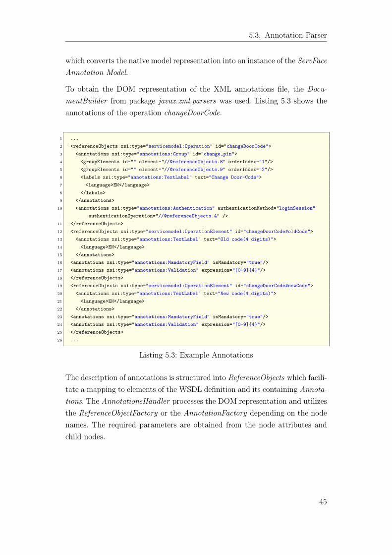
5.3. Annotation-Parser
which converts the native model representation into an instance of the ServFace
Annotation Model.
To obtain the DOM representation of the XML annotations file, the Docu-
mentBuilder from package javax.xml.parsers was used. Listing 5.3 shows the
annotations of the operation changeDoorCode.
1 ...
2 <referenceObjects xsi:type="servicemodel:Operation" id="changeDoorCode">
3 <annotations xsi:type="annotations:Group" id="change_pin">
4 <groupElements id="" element="//@referenceObjects.8" orderIndex="1"/>
5 <groupElements id="" element="//@referenceObjects.9" orderIndex="2"/>
6 <labels xsi:type="annotations:TextLabel" text="Change Door-Code">
7 <language>EN</language>
8 </labels>
9 </annotations>
10 <annotations xsi:type="annotations:Authentication" authenticationMethod="loginSession"
authenticationOperation="//@referenceObjects.4" />
11 </referenceObjects>
12 <referenceObjects xsi:type="servicemodel:OperationElement" id="changeDoorCode#oldCode">
13 <annotations xsi:type="annotations:TextLabel" text="Old code(4 digits)">
14 <language>EN</language>
15 </annotations>
16 <annotations xsi:type="annotations:MandatoryField" isMandatory="true"/>
17 <annotations xsi:type="annotations:Validation" expression="[0-9]{4}"/>
18 </referenceObjects>
19 <referenceObjects xsi:type="servicemodel:OperationElement" id="changeDoorCode#newCode">
20 <annotations xsi:type="annotations:TextLabel" text="New code(4 digits)">
21 <language>EN</language>
22 </annotations>
23 <annotations xsi:type="annotations:MandatoryField" isMandatory="true"/>
24 <annotations xsi:type="annotations:Validation" expression="[0-9]{4}"/>
25 </referenceObjects>
26 ...
Listing 5.3: Example Annotations
The description of annotations is structured into ReferenceObjects which facili-
tate a mapping to elements of the WSDL definition and its containing Annota-
tions. The AnnotationsHandler processes the DOM representation and utilizes
the ReferenceObjectFactory or the AnnotationFactory depending on the node
names. The required parameters are obtained from the node attributes and
child nodes.
45
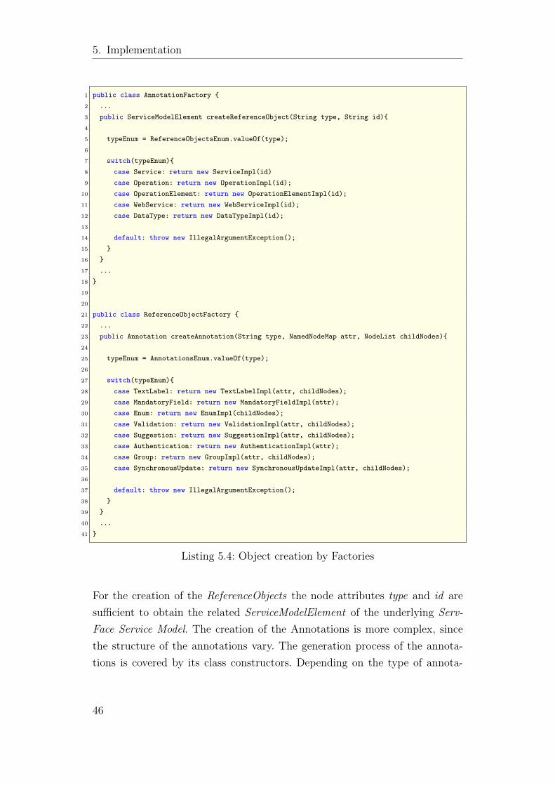
5. Implementation
1 public class AnnotationFactory {
2 ...
3 public ServiceModelElement createReferenceObject(String type, String id){
4
5 typeEnum = ReferenceObjectsEnum.valueOf(type);
6
7 switch(typeEnum){
8 case Service: return new ServiceImpl(id)
9 case Operation: return new OperationImpl(id);
10 case OperationElement: return new OperationElementImpl(id);
11 case WebService: return new WebServiceImpl(id);
12 case DataType: return new DataTypeImpl(id);
13
14 default: throw new IllegalArgumentException();
15 }
16 }
17 ...
18 }
19
20
21 public class ReferenceObjectFactory {
22 ...
23 public Annotation createAnnotation(String type, NamedNodeMap attr, NodeList childNodes){
24
25 typeEnum = AnnotationsEnum.valueOf(type);
26
27 switch(typeEnum){
28 case TextLabel: return new TextLabelImpl(attr, childNodes);
29 case MandatoryField: return new MandatoryFieldImpl(attr);
30 case Enum: return new EnumImpl(childNodes);
31 case Validation: return new ValidationImpl(attr, childNodes);
32 case Suggestion: return new SuggestionImpl(attr, childNodes);
33 case Authentication: return new AuthenticationImpl(attr);
34 case Group: return new GroupImpl(attr, childNodes);
35 case SynchronousUpdate: return new SynchronousUpdateImpl(attr, childNodes);
36
37 default: throw new IllegalArgumentException();
38 }
39 }
40 ...
41 }
Listing 5.4: Object creation by Factories
For the creation of the ReferenceObjects the node attributes type and id are
sufficient to obtain the related ServiceModelElement of the underlying Serv-
Face Service Model. The creation of the Annotations is more complex, since
the structure of the annotations vary. The generation process of the annota-
tions is covered by its class constructors. Depending on the type of annota-
46
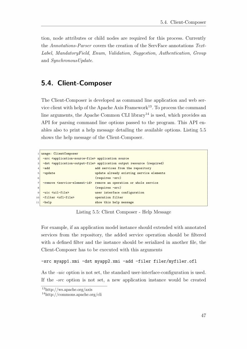
5.4. Client-Composer
tion, node attributes or child nodes are required for this process. Currently
the Annotations-Parser covers the creation of the ServFace annotations Text-
Label, MandatoryField, Enum, Validation, Suggestion, Authentication, Group
and SynchronousUpdate.
5.4. Client-Composer
The Client-Composer is developed as command line application and web ser-
vice client with help of the Apache Axis Framework13. To process the command
line arguments, the Apache Common CLI library14 is used, which provides an
API for parsing command line options passed to the program. This API en-
ables also to print a help message detailing the available options. Listing 5.5
shows the help message of the Client-Composer.
1 usage: ClientComposer
2 -src <application-source-file> application source
3 -dst <application-output-file> application output resource (required)
4 -add add services from the repository
5 -update update already existing service elements
6 (requires -src)
7 -remove <service-element-id> remove an operation or whole service
8 (requires -src)
9 -uic <uil-file> user interface configuration
10 -filter <ofl-file> operation filter
11 -help show this help message
Listing 5.5: Client Composer - Help Message
For example, if an application model instance should extended with annotated
services from the repository, the added service operation should be filtered
with a defined filter and the instance should be serialized in another file, the
Client-Composer has to be executed with this arguments
-src myapp1.xmi -dst myapp2.xmi -add -filer filer/myfiler.ofl
As the -uic option is not set, the standard user-interface-configuration is used.
If the -src option is not set, a new application instance would be created
13http://ws.apache.org/axis14http://commons.apache.org/cli
47
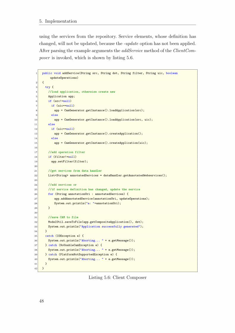
5. Implementation
using the services from the repository. Service elements, whose definition has
changed, will not be updated, because the -update option has not been applied.
After parsing the example arguments the addService method of the ClientCom-
poser is invoked, which is shown by listing 5.6.
1 public void addService(String src, String dst, String filter, String uic, boolean
updateOperations)
2 {
3 try {
4 //load application, otherwise create new
5 Application app;
6 if (src!=null)
7 if (uic==null)
8 app = CamGenerator.getInstance().loadApplication(src);
9 else
10 app = CamGenerator.getInstance().loadApplication(src, uic);
11 else
12 if (uic==null)
13 app = CamGenerator.getInstance().createApplication();
14 else
15 app = CamGenerator.getInstance().createApplication(uic);
16
17 //add operation filter
18 if (filter!=null)
19 app.setFilter(filter);
20
21 //get services from data handler
22 List<String> annotatedServices = dataHandler.getAnnotatedWebservices();
23
24 //add services or
25 //if service definition has changed, update the service
26 for (String annotationUri : annotatedServices) {
27 app.addAnnotatedService(annotationUri, updateOperations);
28 System.out.println("a: "+annotationUri);
29 }
30
31 //save CAM to file
32 ModelUtil.saveToFile(app.getCompositeApplication(), dst);
33 System.out.println("Application successfully generated");
34 }
35 catch (IOException e) {
36 System.out.println("Aborting... " + e.getMessage());
37 } catch (NoUsableCamException e) {
38 System.out.println("Aborting... " + e.getMessage());
39 } catch (PlatformNotSupportedException e) {
40 System.out.println("Aborting... " + e.getMessage());
41 }
42 }
Listing 5.6: Client Composer
48

5.4. Client-Composer
The four parameters correspond to the command line arguments of the Client-
Composer. As already mentioned, if no source is passed, a new application
model instance will be created. The resulting application will be serialized to
a file, which is defined by the dst parameter. The third parameter defines the
operation filter file, which is passed to the application. Such a filter file has
been already presented in listing 4.1 on page 34. A user-interface-configuration,
which is defined by the uic parameter, is not used in this example. In such a
case the standard configuration of the Model-Generator is used, which also has
been already presented in listing 4.2 on page 36.
The used interface dataHandler in the ClientComposer class is implemented
by the DSHandler, which implements the method getAnnotatedWebservices
showing in listing 5.7.
1 public class DSHandler implements DataHandler {
2
3 private DirectoryServicePortType ds_portType;
4
5 public DSHandler() throws ServiceException
6 {
7 //create directory service stub
8 DirectoryServiceLocator dsLocator = new DirectoryServiceLocator();
9 ds_portType = dsLocator.getDirectoryServiceHttpSoap12Endpoint();
10 }
11
12 @Override
13 public List<String> getAnnotatedWebservices()
14 {
15 List<String> annotationUriList = new ArrayList<String>();
16 try {
17 //invoke directory service
18 AnnotatedWebservice[] aWebservices = ds_portType.getWebservices();
19 annotationUriList = new ArrayList<String>();
20 for (AnnotatedWebservice aWebservice : aWebservices) {
21 annotationUriList.add(aWebservice.getAnnotationsURI());
22 }
23 }
24 catch (RemoteException e) {
25 System.out.println("Error during invoking the directory service!");
26 System.out.println("See settings.properties for service configuration.");
27 }
28 return annotationUriList;
29 }
30 }
Listing 5.7: Directory Service Handler
49
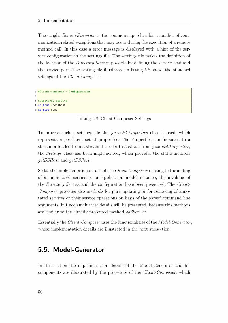
5. Implementation
The caught RemoteException is the common superclass for a number of com-
munication related exceptions that may occur during the execution of a remote
method call. In this case a error message is displayed with a hint of the ser-
vice configuration in the settings file. The settings file makes the definition of
the location of the Directory Service possible by defining the service host and
the service port. The setting file illustrated in listing 5.8 shows the standard
settings of the Client-Composer.
1 #Client-Composer - Configuration
2
3 #directory service
4 ds_host localhost
5 ds_port 8080
Listing 5.8: Client-Composer Settings
To process such a settings file the java.util.Properties class is used, which
represents a persistent set of properties. The Properties can be saved to a
stream or loaded from a stream. In order to abstract from java.util.Properties,
the Settings class has been implemented, which provides the static methods
getDSHost and getDSPort.
So far the implementation details of the Client-Composer relating to the adding
of an annotated service to an application model instance, the invoking of
the Directory Service and the configuration have been presented. The Client-
Composer provides also methods for pure updating or for removing of anno-
tated services or their service operations on basis of the parsed command line
arguments, but not any further details will be presented, because this methods
are similar to the already presented method addService.
Essentially the Client-Composer uses the functionalities of the Model-Generator,
whose implementation details are illustrated in the next subsection.
5.5. Model-Generator
In this section the implementation details of the Model-Generator and his
components are illustrated by the procedure of the Client-Composer, which
50
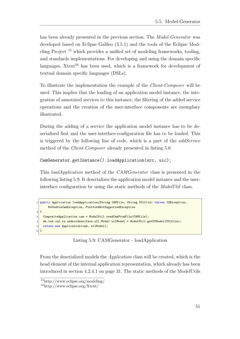
5.5. Model-Generator
has been already presented in the previous section. The Model-Generator was
developed based on Eclipse Galileo (3.5.1) and the tools of the Eclipse Mod-
eling Project 15 which provides a unified set of modeling frameworks, tooling,
and standards implementations. For developing and using the domain specific
languages, Xtext16 has been used, which is a framework for development of
textual domain specific languages (DSLs).
To illustrate the implementation the example of the Client-Composer will be
used. This implies that the loading of an application model instance, the inte-
gration of annotated services to this instance, the filtering of the added service
operations and the creation of the user-interface components are exemplary
illustrated.
During the adding of a service the application model instance has to be de-
serialized first and the user-interface-configuration file has to be loaded. This
is triggered by the following line of code, which is a part of the addService
method of the Client-Composer already presented in listing 5.6
CamGenerator.getInstance().loadApplication(src, uic);
This loadApplication method of the CAMGenerator class is presented in the
following listing 5.9. It deserializes the application model instance and the user-
interface configuration by using the static methods of the ModelUtil class.
1 public Application loadApplication(String CAMfile, String UILfile) throws IOException,
NoUsableCamException, PlatformNotSupportedException
2 {
3 CompositeApplication cam = ModelUtil.readCamFromFile(CAMfile);
4 de.tud.inf.rn.androidservface.uIl.Model uilModel = ModelUtil.getUIModel(UILfile);
5 return new Application(cam, uilModel);
6 }
Listing 5.9: CAMGenerator - loadApplication
From the deserialized models the Application class will be created, which is the
head element of the internal application representation, which already has been
introduced in section 4.2.4.1 on page 31. The static methods of the ModelUtils
15http://www.eclipse.org/modeling/16http://www.eclipse.org/Xtext/
51
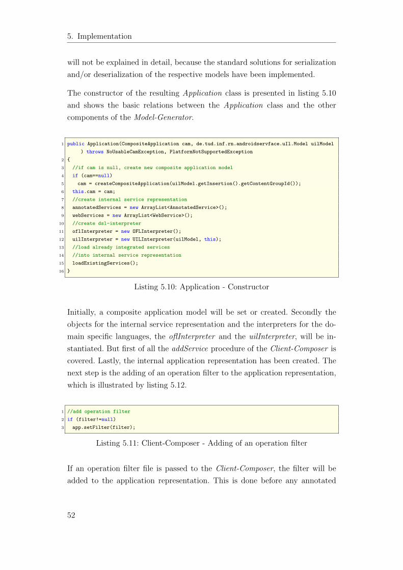
5. Implementation
will not be explained in detail, because the standard solutions for serialization
and/or deserialization of the respective models have been implemented.
The constructor of the resulting Application class is presented in listing 5.10
and shows the basic relations between the Application class and the other
components of the Model-Generator.
1 public Application(CompositeApplication cam, de.tud.inf.rn.androidservface.uIl.Model uilModel
) throws NoUsableCamException, PlatformNotSupportedException
2 {
3 //if cam is null, create new composite application model
4 if (cam==null)
5 cam = createCompositeApplication(uilModel.getInsertion().getContentGroupId());
6 this.cam = cam;
7 //create internal service representation
8 annotatedServices = new ArrayList<AnnotatedService>();
9 webServices = new ArrayList<WebService>();
10 //create dsl-interpreter
11 oflInterpreter = new OFLInterpreter();
12 uilInterpreter = new UILInterpreter(uilModel, this);
13 //load already integrated services
14 //into internal service representation
15 loadExistingServices();
16 }
Listing 5.10: Application - Constructor
Initially, a composite application model will be set or created. Secondly the
objects for the internal service representation and the interpreters for the do-
main specific languages, the oflInterpreter and the uilInterpreter, will be in-
stantiated. But first of all the addService procedure of the Client-Composer is
covered. Lastly, the internal application representation has been created. The
next step is the adding of an operation filter to the application representation,
which is illustrated by listing 5.12.
1 //add operation filter
2 if (filter!=null)
3 app.setFilter(filter);
Listing 5.11: Client-Composer - Adding of an operation filter
If an operation filter file is passed to the Client-Composer, the filter will be
added to the application representation. This is done before any annotated
52
5.5. Model-Generator
service will be added to the application. So far the filter file, if it is passed by
the command line option, and the user-interface configuration file are passed to
the internal application representation. Out of these files the respective inter-
preters will be parametrized, whose implementation details will be explained
in subsection 5.5.1.
After the creation of the interpreter and adding the already existing service
elements to the internal service representation, the annotated services from
the repository will be added to the application by the code presented in listing
5.12 of the Client-Composer.
1 //get services from data handler
2 List<String> annotatedServices = dataHandler.getAnnotatedWebservices();
3 //add services or
4 //if service definition has changed, update the service
5 for (String annotationUri : annotatedServices) {
6 app.addAnnotatedService(annotationUri, updateOperations);
7 System.out.println("a: "+annotationUri);
8 }
Listing 5.12: Adding of annotated services filter
The procedure of adding of services will be illustrated in subsection 5.5.2. Fi-
nally the resulting application will be serialized as xmi file as already mentioned
in the section of the Client-Composer.
5.5.1. DSL-Interpreter
Both domain specific languages, the Operation Filter Language and the User-
Interface-Language, were developed with the help of the Xtext Framework.
Before examining the respective interpreters, the development process of a DSL
with Xtext will be illustrated. As already mentioned Xtext is a framework for
development of textual domain specific languages, which is available as eclipse
plugin. The language will be described by an EBNF grammar. Both grammars
can be found in the appendix A.1 and A.2. This grammar builds the core
and defines a textual syntax for EMF-models17. Xtext generates then a meta
17Eclipse Modeling Framework (EMF) is an eclipse-based modeling framework,http://www.eclipse.org/modeling/emf/
53
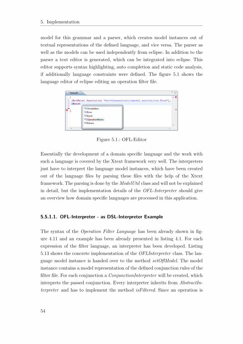
5. Implementation
model for this grammar and a parser, which creates model instances out of
textual representations of the defined language, and vice versa. The parser as
well as the models can be used independently from eclipse. In addition to the
parser a text editor is generated, which can be integrated into eclipse. This
editor supports syntax highlighting, auto completion and static code analysis,
if additionally language constraints were defined. The figure 5.1 shows the
language editor of eclipse editing an operation filter file.
Figure 5.1.: OFL-Editor
Essentially the development of a domain specific language and the work with
such a language is covered by the Xtext framework very well. The interpreters
just have to interpret the language model instances, which have been created
out of the language files by parsing these files with the help of the Xtext
framework. The parsing is done by the ModelUtil class and will not be explained
in detail, but the implementation details of the OFL-Interpreter should give
an overview how domain specific languages are processed in this application.
5.5.1.1. OFL-Interpreter - as DSL-Interpreter Example
The syntax of the Operation Filter Language has been already shown in fig-
ure 4.11 and an example has been already presented in listing 4.1. For each
expression of the filter language, an interpreter has been developed. Listing
5.13 shows the concrete implementation of the OFLInterpreter class. The lan-
guage model instance is handed over to the method setOflModel. The model
instance contains a model representation of the defined conjunction rules of the
filter file. For each conjunction a ConjunctionInterpreter will be created, which
interprets the passed conjunction. Every interpreter inherits from AbstractIn-
terpreter and has to implement the method isFiltered. Since an operation is
54
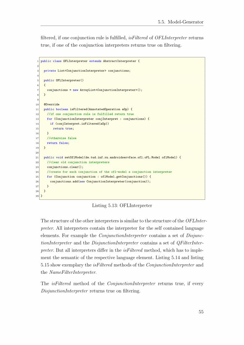
5.5. Model-Generator
filtered, if one conjunction rule is fulfilled, isFiltered of OFLInterpreter returns
true, if one of the conjunction interpreters returns true on filtering.
1 public class OFLInterpreter extends AbstractInterpreter {
2
3 private List<ConjunctionInterpreter> conjunctions;
4
5 public OFLInterpreter()
6 {
7 conjunctions = new ArrayList<ConjunctionInterpreter>();
8 }
9
10 @Override
11 public boolean isFiltered(AnnotatedOperation aOp) {
12 //if one conjunction rule is fulfilled return true
13 for (ConjunctionInterpreter conjInterpret : conjunctions) {
14 if (conjInterpret.isFiltered(aOp))
15 return true;
16 }
17 //otherwise false
18 return false;
19 }
20
21 public void setOflModel(de.tud.inf.rn.androidservface.ofl.oFL.Model oflModel) {
22 //clear old conjunction interpreters
23 conjunctions.clear();
24 //create for each conjunction of the ofl-model a conjunction interpreter
25 for (Conjunction conjunction : oflModel.getConjunctions()) {
26 conjunctions.add(new ConjunctionInterpreter(conjunction));
27 }
28 }
29 }
Listing 5.13: OFLInterpreter
The structure of the other interpreters is similar to the structure of the OFLInter-
preter. All interpreters contain the interpreter for the self contained language
elements. For example the ConjunctionInterpreter contains a set of Disjunc-
tionInterpreter and the DisjunctionInterpreter contains a set of QFilterInter-
preter. But all interpreters differ in the isFiltered method, which has to imple-
ment the semantic of the respective language element. Listing 5.14 and listing
5.15 show exemplary the isFiltered methods of the ConjunctionInterpreter and
the NameFilterInterpreter.
The isFiltered method of the ConjunctionInterpreter returns true, if every
DisjunctionInterpreter returns true on filtering.
55
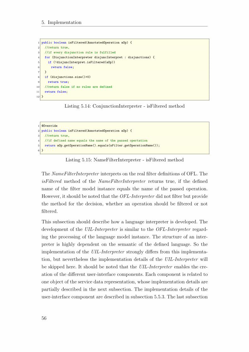
5. Implementation
1 public boolean isFiltered(AnnotatedOperation aOp) {
2 //return true,
3 //if every disjunction rule is fulfilled
4 for (DisjunctionInterpreter disjuncInterpret : disjunctions) {
5 if (!disjuncInterpret.isFiltered(aOp))
6 return false;
7 }
8 if (disjunctions.size()>0)
9 return true;
10 //return false if no rules are defined
11 return false;
12 }
Listing 5.14: ConjunctionInterpreter - isFiltered method
1 @Override
2 public boolean isFiltered(AnnotatedOperation aOp) {
3 //return true,
4 //if defined name equals the name of the passed opertation
5 return aOp.getOperationName().equals(nFilter.getOperationName());
6 }
Listing 5.15: NameFilterInterpreter - isFiltered method
The NameFilterInterpreter interprets on the real filter definitions of OFL. The
isFiltered method of the NameFilterInterpreter returns true, if the defined
name of the filter model instance equals the name of the passed operation.
However, it should be noted that the OFL-Interpreter did not filter but provide
the method for the decision, whether an operation should be filtered or not
filtered.
This subsection should describe how a language interpreter is developed. The
development of the UIL-Interpreter is similar to the OFL-Interpreter regard-
ing the processing of the language model instance. The structure of an inter-
preter is highly dependent on the semantic of the defined language. So the
implementation of the UIL-Interpreter strongly differs from this implementa-
tion, but nevertheless the implementation details of the UIL-Interpreter will
be skipped here. It should be noted that the UIL-Interpreter enables the cre-
ation of the different user-interface components. Each component is related to
one object of the service data representation, whose implementation details are
partially described in the next subsection. The implementation details of the
user-interface component are described in subsection 5.5.3. The last subsection
56
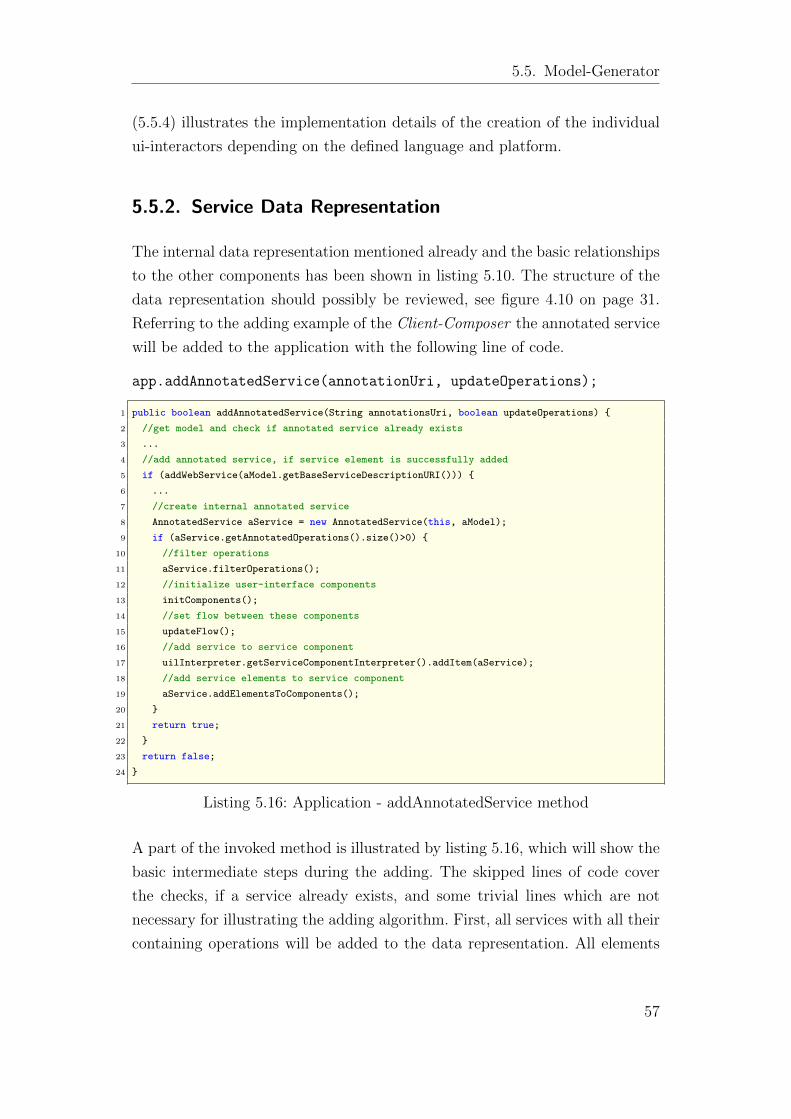
5.5. Model-Generator
(5.5.4) illustrates the implementation details of the creation of the individual
ui-interactors depending on the defined language and platform.
5.5.2. Service Data Representation
The internal data representation mentioned already and the basic relationships
to the other components has been shown in listing 5.10. The structure of the
data representation should possibly be reviewed, see figure 4.10 on page 31.
Referring to the adding example of the Client-Composer the annotated service
will be added to the application with the following line of code.
app.addAnnotatedService(annotationUri, updateOperations);
1 public boolean addAnnotatedService(String annotationsUri, boolean updateOperations) {
2 //get model and check if annotated service already exists
3 ...
4 //add annotated service, if service element is successfully added
5 if (addWebService(aModel.getBaseServiceDescriptionURI())) {
6 ...
7 //create internal annotated service
8 AnnotatedService aService = new AnnotatedService(this, aModel);
9 if (aService.getAnnotatedOperations().size()>0) {
10 //filter operations
11 aService.filterOperations();
12 //initialize user-interface components
13 initComponents();
14 //set flow between these components
15 updateFlow();
16 //add service to service component
17 uilInterpreter.getServiceComponentInterpreter().addItem(aService);
18 //add service elements to service component
19 aService.addElementsToComponents();
20 }
21 return true;
22 }
23 return false;
24 }
Listing 5.16: Application - addAnnotatedService method
A part of the invoked method is illustrated by listing 5.16, which will show the
basic intermediate steps during the adding. The skipped lines of code cover
the checks, if a service already exists, and some trivial lines which are not
necessary for illustrating the adding algorithm. First, all services with all their
containing operations will be added to the data representation. All elements
57
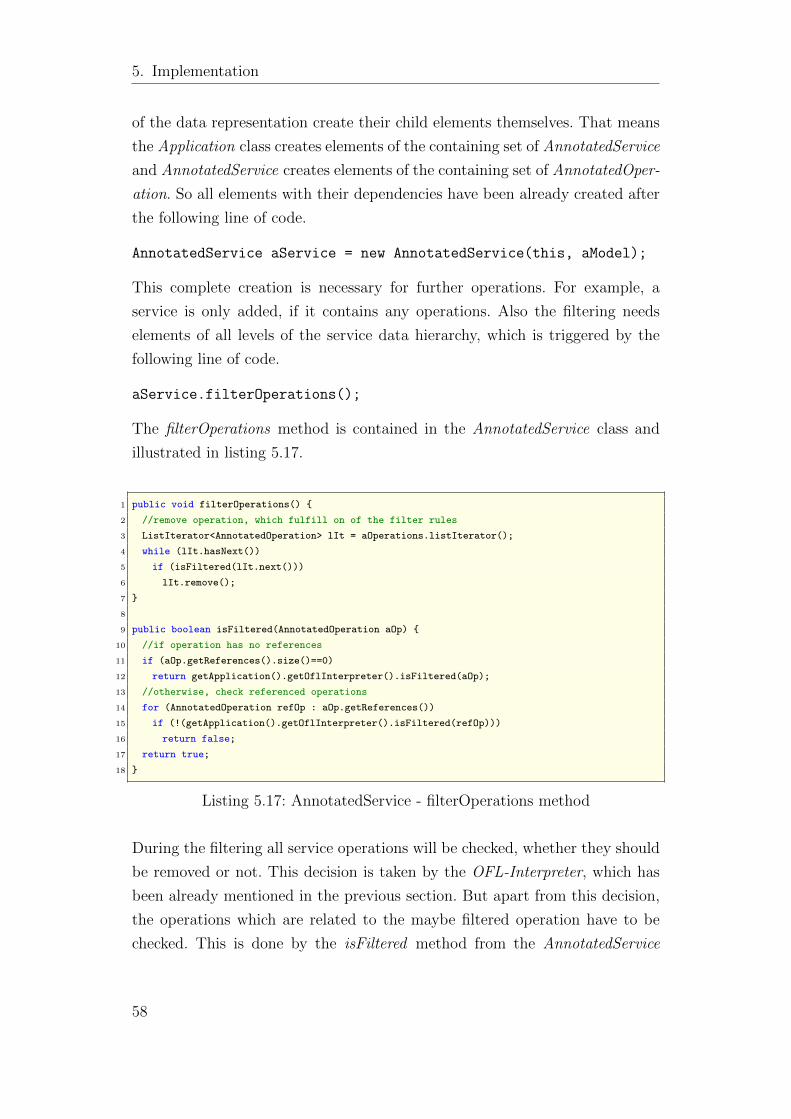
5. Implementation
of the data representation create their child elements themselves. That means
the Application class creates elements of the containing set of AnnotatedService
and AnnotatedService creates elements of the containing set of AnnotatedOper-
ation. So all elements with their dependencies have been already created after
the following line of code.
AnnotatedService aService = new AnnotatedService(this, aModel);
This complete creation is necessary for further operations. For example, a
service is only added, if it contains any operations. Also the filtering needs
elements of all levels of the service data hierarchy, which is triggered by the
following line of code.
aService.filterOperations();
The filterOperations method is contained in the AnnotatedService class and
illustrated in listing 5.17.
1 public void filterOperations() {
2 //remove operation, which fulfill on of the filter rules
3 ListIterator<AnnotatedOperation> lIt = aOperations.listIterator();
4 while (lIt.hasNext())
5 if (isFiltered(lIt.next()))
6 lIt.remove();
7 }
8
9 public boolean isFiltered(AnnotatedOperation aOp) {
10 //if operation has no references
11 if (aOp.getReferences().size()==0)
12 return getApplication().getOflInterpreter().isFiltered(aOp);
13 //otherwise, check referenced operations
14 for (AnnotatedOperation refOp : aOp.getReferences())
15 if (!(getApplication().getOflInterpreter().isFiltered(refOp)))
16 return false;
17 return true;
18 }
Listing 5.17: AnnotatedService - filterOperations method
During the filtering all service operations will be checked, whether they should
be removed or not. This decision is taken by the OFL-Interpreter, which has
been already mentioned in the previous section. But apart from this decision,
the operations which are related to the maybe filtered operation have to be
checked. This is done by the isFiltered method from the AnnotatedService
58
5.5. Model-Generator
class. An operation is only then filtered, if all related operations will be also
filtered, to prevent inconsistencies.
Back to the adding procedure, after the filtering of the operations, the user-
interface components will be initialized. The line of code, initComponents();,
from the addAnnotatedService method invokes the method illustrated by listing
5.19.
1 private void initComponents() {
2 uilInterpreter.getServiceComponentInterpreter().init();
3 for (AnnotatedService aService : annotatedServices)
4 aService.initComponents();
5
6 }
Listing 5.18: AnnotatedService - initComponents method
Here the service component, which displays all added services, and all nested
components of the contained services will be initialized. The implementation
details of the creation of the user-interface elements will be illustrated in the
following subsection.
5.5.3. User-Interface Components
The user-interface components are responsible for the adding of the user-
interface elements to the Composite Application Model. Four different types
of components have been classified, which have also already been illustrated
in figure 4.4 on 23. The service-component lists all added services, the opera-
tion component lists all operations of a service, the input component lists all
input fields of an operation and the output component shows the output of an
operation. The structure of the components and their relations have been al-
ready presented in figure 4.14 on page 38. Parametrized are the components by
the information of the user-interface configuration file, which will be evaluated
by the UIL-Interpreter. The implementations details of the UIL-Interpreter
regarding the parsing of the UIL-file corresponds to the parsing by the OFL-
Interpreter (see subsection 5.5.1.1) and will be skipped here. These components
are created by the UIL-Interpreter using the information of the UIL-file. All
59
5. Implementation
components operate directly on the application model. The already mentioned
init method is illustrated in listing 5.19.
1 public final void init()
2 {
3 int pageId = 0;
4 //get page form application model
5 Page sPage = ModelHelper.getPageFromCamById(uilInterpreter.getCompositeApplication(),
getPageId(0));
6 //if page not exists, create ui-elements
7 if (sPage==null)
8 createComponents();
9 ...
10 //init all possible existing pages
11 sPage = ModelHelper.getPageFromCamById(uilInterpreter.getCompositeApplication(), getPageId
(0));
12 while (sPage!=null) {
13 ContentGroup cGrp = ModelHelper.getContentGroupFromPageById(sPage, getContentGroupId(
pageId));
14 if (cGrp!=null)
15 if (!pages.contains(sPage)) {
16 pages.add(sPage);
17 contentGroups.add(cGrp);
18 }
19 pageId++;
20 sPage = ModelHelper.getPageFromCamById(uilInterpreter.getCompositeApplication(), getPageId
(pageId));
21 }
22 initInternalComponents();
23 }
Listing 5.19: AbstractComponentInterpreter - init method
A component contains a set of available pages and content groups. During
the initialization the already existing pages have to be found or a initial page
has to be created, which is done by the internal createComponents method.
To retrieve the information, which page relates to which component, the only
usable information is stored in the id of each page. The static method getPage-
FromCamById of the ModelHelper class searches for a page with given id. The
method getPageId(0) returns the id of the first page for that component. Each
component is associated with an element of the service data representation,
which has an id created out of the hash value of the service description uri
and the type of the service element. So the id of that page, which contains the
elements representing the operations of a service, looks like the id shown in
listing 5.20.
60
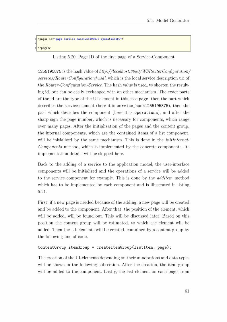
5.5. Model-Generator
1 <pages id="page_service_hash1255195875_operations#0">
2 ...
3 </pages>
Listing 5.20: Page ID of the first page of a Service-Component
1255195875 is the hash value of http://localhost:8080/WSRouterConfiguration/
services/RouterConfiguration?wsdl, which is the local service description uri of
the Router-Configuration-Service. The hash value is used, to shorten the result-
ing id, but can be easily exchanged with an other mechanism. The exact parts
of the id are the type of the UI-element in this case page, then the part which
describes the service element (here it is service_hash1255195875), then the
part which describes the component (here it is operations), and after the
sharp sign the page number, which is necessary for components, which range
over many pages. After the initialization of the pages and the content group,
the internal components, which are the contained items of a list component,
will be initialized by the same mechanism. This is done in the initInternal-
Components method, which is implemented by the concrete components. Its
implementation details will be skipped here.
Back to the adding of a service to the application model, the user-interface
components will be initialized and the operations of a service will be added
to the service component for example. This is done by the addItem method
which has to be implemented by each component and is illustrated in listing
5.21.
First, if a new page is needed because of the adding, a new page will be created
and be added to the component. After that, the position of the element, which
will be added, will be found out. This will be discussed later. Based on this
position the content group will be estimated, to which the element will be
added. Then the UI-elements will be created, contained by a content group by
the following line of code.
ContentGroup itemGroup = createItemGroup(listItem, page);
The creation of the UI-elements depending on their annotations and data types
will be shown in the following subsection. After the creation, the item group
will be added to the component. Lastly, the last element on each page, from
61
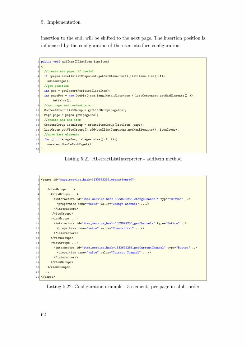
5. Implementation
insertion to the end, will be shifted to the next page. The insertion position is
influenced by the configuration of the user-interface configuration.
1 public void addItem(IListItem listItem)
2 {
3 //create new page, if needed
4 if (pages.size()*listComponent.getMaxElements()<(listItems.size()+1))
5 addNewPage();
6 //get position
7 int pos = getInsertPosition(listItem);
8 int pagePos = new Double(java.lang.Math.floor(pos / listComponent.getMaxElements() )).
intValue();
9 //get page and content group
10 ContentGroup listGroup = getListGroup(pagePos);
11 Page page = pages.get(pagePos);
12 //create and add item
13 ContentGroup itemGroup = createItemGroup(listItem, page);
14 listGroup.getViewGroups().add(pos%listComponent.getMaxElements(), itemGroup);
15 //move last elements
16 for (int i=pagePos; i<pages.size()-1; i++)
17 moveLastItemToNextPage(i);
18 }
Listing 5.21: AbstractListInterpreter - addItem method
1 <pages id="page_service_hash-1333692256_operations#0">
2 ...
3 <viewGroups ...>
4 <viewGroups ...>
5 <interactors id="item_service_hash-1333692256_changeChannel" type="Button" ..>
6 <properties name="value" value="Change Channel" .../>
7 </interactors>
8 </viewGroups>
9 <viewGroups ...>
10 <interactors id="item_service_hash-1333692256_getChannels" type="Button" ..>
11 <properties name="value" value="Channellist" .../>
12 </interactors>
13 </viewGroups>
14 <viewGroups ...>
15 <interactors id="item_service_hash-1333692256_getCurrentChannel" type="Button" ..>
16 <properties name="value" value="Current Channel" .../>
17 </interactors>
18 </viewGroups>
19 </viewGroups>
20 ...
21 </pages>
Listing 5.22: Configuration example - 3 elements per page in alph. order
62
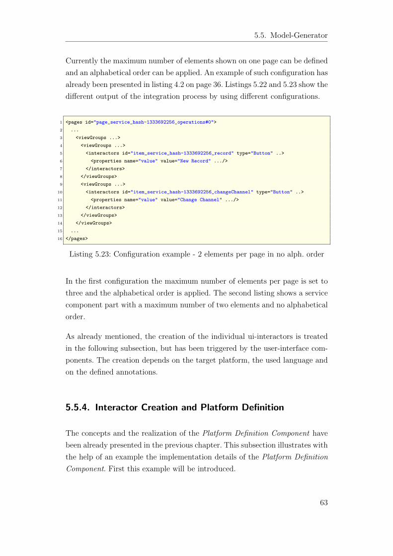
5.5. Model-Generator
Currently the maximum number of elements shown on one page can be defined
and an alphabetical order can be applied. An example of such configuration has
already been presented in listing 4.2 on page 36. Listings 5.22 and 5.23 show the
different output of the integration process by using different configurations.
1 <pages id="page_service_hash-1333692256_operations#0">
2 ...
3 <viewGroups ...>
4 <viewGroups ...>
5 <interactors id="item_service_hash-1333692256_record" type="Button" ..>
6 <properties name="value" value="New Record" .../>
7 </interactors>
8 </viewGroups>
9 <viewGroups ...>
10 <interactors id="item_service_hash-1333692256_changeChannel" type="Button" ..>
11 <properties name="value" value="Change Channel" .../>
12 </interactors>
13 </viewGroups>
14 </viewGroups>
15 ...
16 </pages>
Listing 5.23: Configuration example - 2 elements per page in no alph. order
In the first configuration the maximum number of elements per page is set to
three and the alphabetical order is applied. The second listing shows a service
component part with a maximum number of two elements and no alphabetical
order.
As already mentioned, the creation of the individual ui-interactors is treated
in the following subsection, but has been triggered by the user-interface com-
ponents. The creation depends on the target platform, the used language and
on the defined annotations.
5.5.4. Interactor Creation and Platform Definition
The concepts and the realization of the Platform Definition Component have
been already presented in the previous chapter. This subsection illustrates with
the help of an example the implementation details of the Platform Definition
Component. First this example will be introduced.
63
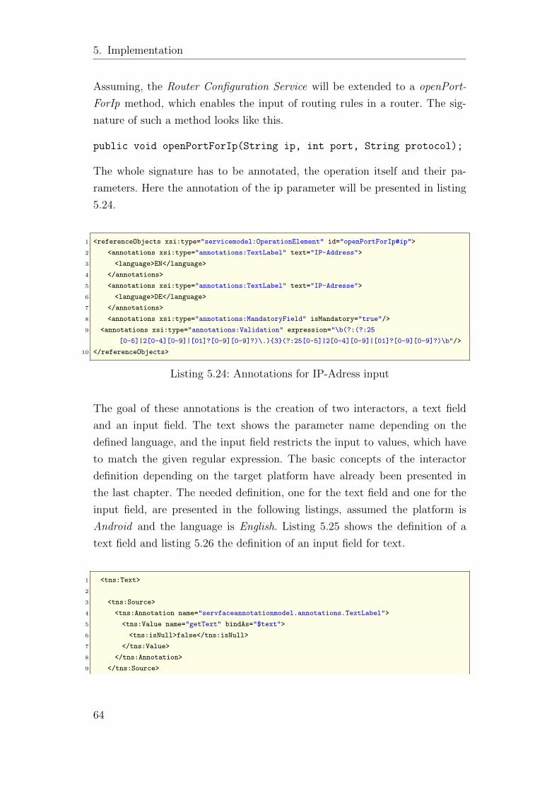
5. Implementation
Assuming, the Router Configuration Service will be extended to a openPort-
ForIp method, which enables the input of routing rules in a router. The sig-
nature of such a method looks like this.
public void openPortForIp(String ip, int port, String protocol);
The whole signature has to be annotated, the operation itself and their pa-
rameters. Here the annotation of the ip parameter will be presented in listing
5.24.
1 <referenceObjects xsi:type="servicemodel:OperationElement" id="openPortForIp#ip">
2 <annotations xsi:type="annotations:TextLabel" text="IP-Address">
3 <language>EN</language>
4 </annotations>
5 <annotations xsi:type="annotations:TextLabel" text="IP-Adresse">
6 <language>DE</language>
7 </annotations>
8 <annotations xsi:type="annotations:MandatoryField" isMandatory="true"/>
9 <annotations xsi:type="annotations:Validation" expression="\b(?:(?:25
[0-5]|2[0-4][0-9]|[01]?[0-9][0-9]?)\.){3}(?:25[0-5]|2[0-4][0-9]|[01]?[0-9][0-9]?)\b"/>
10 </referenceObjects>
Listing 5.24: Annotations for IP-Adress input
The goal of these annotations is the creation of two interactors, a text field
and an input field. The text shows the parameter name depending on the
defined language, and the input field restricts the input to values, which have
to match the given regular expression. The basic concepts of the interactor
definition depending on the target platform have already been presented in
the last chapter. The needed definition, one for the text field and one for the
input field, are presented in the following listings, assumed the platform is
Android and the language is English. Listing 5.25 shows the definition of a
text field and listing 5.26 the definition of an input field for text.
1 <tns:Text>
2
3 <tns:Source>
4 <tns:Annotation name="servfaceannotationmodel.annotations.TextLabel">
5 <tns:Value name="getText" bindAs="$text">
6 <tns:isNull>false</tns:isNull>
7 </tns:Value>
8 </tns:Annotation>
9 </tns:Source>
64
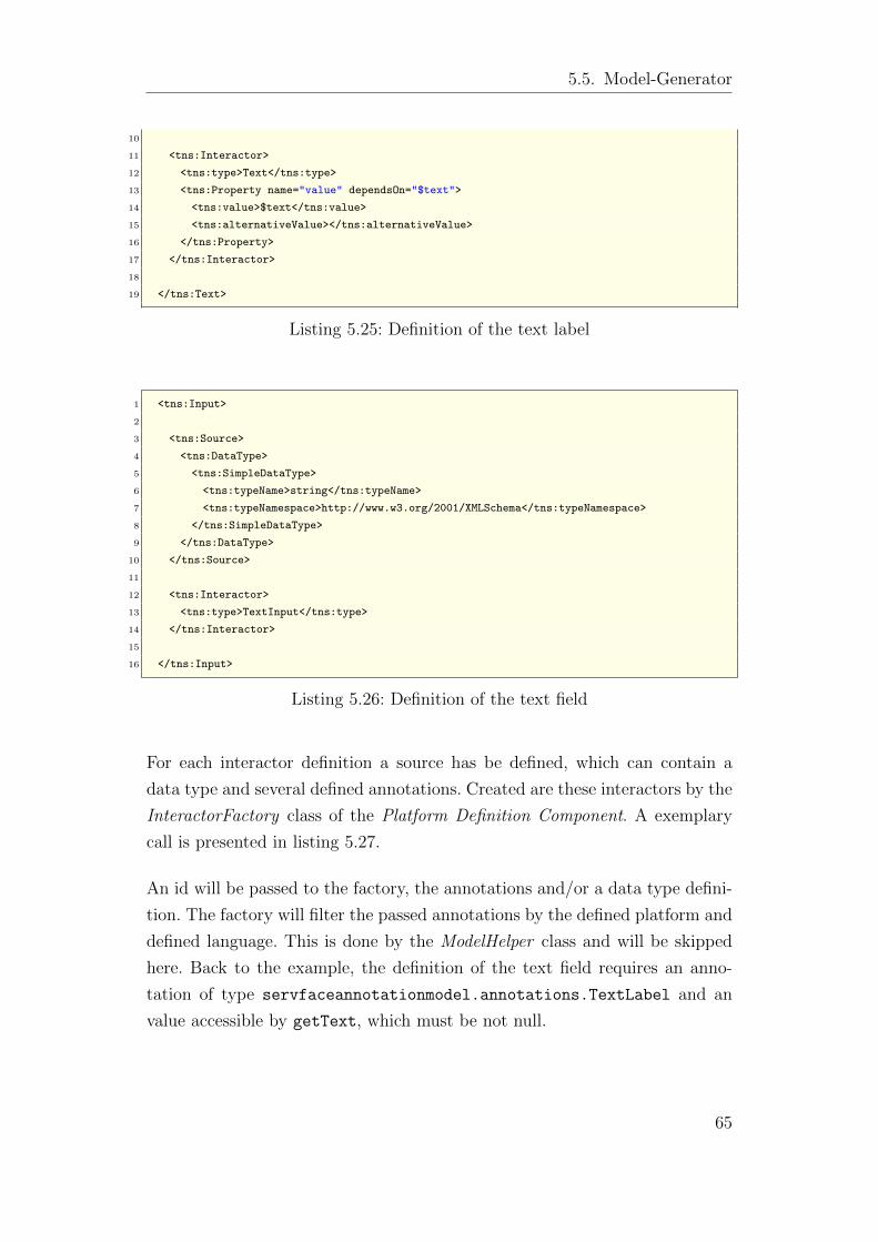
5.5. Model-Generator
10
11 <tns:Interactor>
12 <tns:type>Text</tns:type>
13 <tns:Property name="value" dependsOn="$text">
14 <tns:value>$text</tns:value>
15 <tns:alternativeValue></tns:alternativeValue>
16 </tns:Property>
17 </tns:Interactor>
18
19 </tns:Text>
Listing 5.25: Definition of the text label
1 <tns:Input>
2
3 <tns:Source>
4 <tns:DataType>
5 <tns:SimpleDataType>
6 <tns:typeName>string</tns:typeName>
7 <tns:typeNamespace>http://www.w3.org/2001/XMLSchema</tns:typeNamespace>
8 </tns:SimpleDataType>
9 </tns:DataType>
10 </tns:Source>
11
12 <tns:Interactor>
13 <tns:type>TextInput</tns:type>
14 </tns:Interactor>
15
16 </tns:Input>
Listing 5.26: Definition of the text field
For each interactor definition a source has be defined, which can contain a
data type and several defined annotations. Created are these interactors by the
InteractorFactory class of the Platform Definition Component. A exemplary
call is presented in listing 5.27.
An id will be passed to the factory, the annotations and/or a data type defini-
tion. The factory will filter the passed annotations by the defined platform and
defined language. This is done by the ModelHelper class and will be skipped
here. Back to the example, the definition of the text field requires an anno-
tation of type servfaceannotationmodel.annotations.TextLabel and an
value accessible by getText, which must be not null.
65
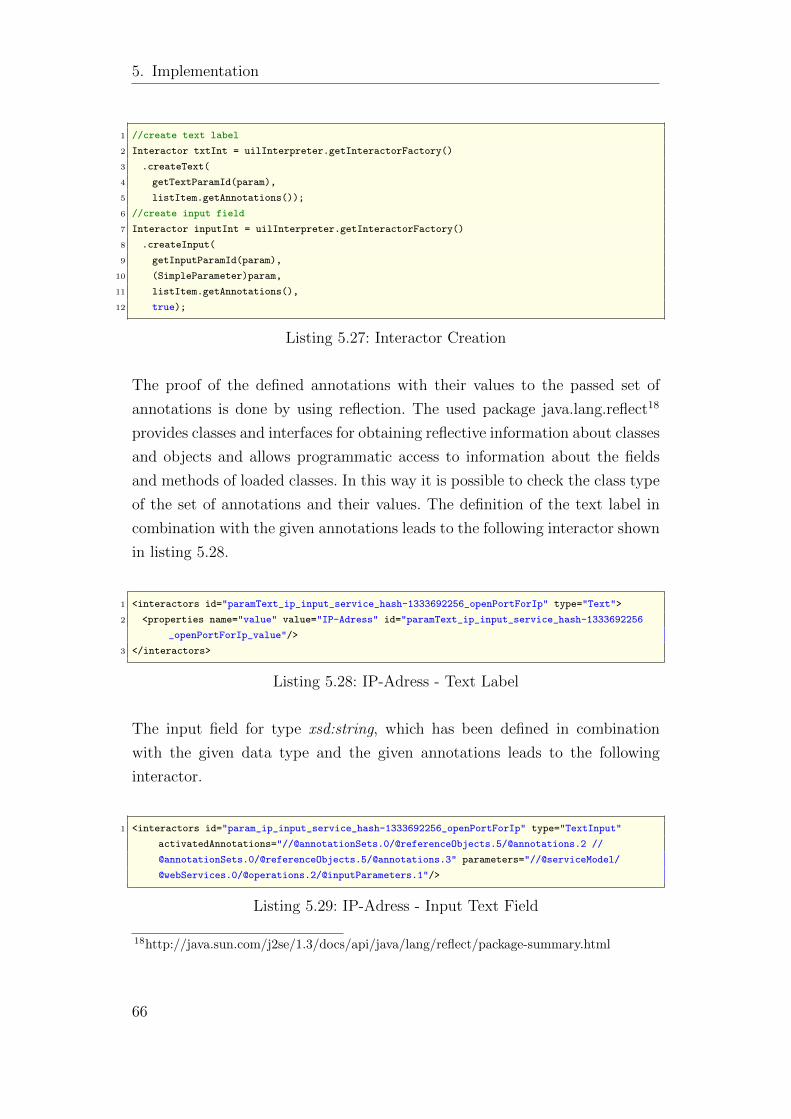
5. Implementation
1 //create text label
2 Interactor txtInt = uilInterpreter.getInteractorFactory()
3 .createText(
4 getTextParamId(param),
5 listItem.getAnnotations());
6 //create input field
7 Interactor inputInt = uilInterpreter.getInteractorFactory()
8 .createInput(
9 getInputParamId(param),
10 (SimpleParameter)param,
11 listItem.getAnnotations(),
12 true);
Listing 5.27: Interactor Creation
The proof of the defined annotations with their values to the passed set of
annotations is done by using reflection. The used package java.lang.reflect18
provides classes and interfaces for obtaining reflective information about classes
and objects and allows programmatic access to information about the fields
and methods of loaded classes. In this way it is possible to check the class type
of the set of annotations and their values. The definition of the text label in
combination with the given annotations leads to the following interactor shown
in listing 5.28.
1 <interactors id="paramText_ip_input_service_hash-1333692256_openPortForIp" type="Text">
2 <properties name="value" value="IP-Adress" id="paramText_ip_input_service_hash-1333692256
_openPortForIp_value"/>
3 </interactors>
Listing 5.28: IP-Adress - Text Label
The input field for type xsd:string, which has been defined in combination
with the given data type and the given annotations leads to the following
interactor.
1 <interactors id="param_ip_input_service_hash-1333692256_openPortForIp" type="TextInput"
activatedAnnotations="//@annotationSets.0/@referenceObjects.5/@annotations.2 //
@annotationSets.0/@referenceObjects.5/@annotations.3" parameters="//@serviceModel/
@webServices.0/@operations.2/@inputParameters.1"/>
Listing 5.29: IP-Adress - Input Text Field
18http://java.sun.com/j2se/1.3/docs/api/java/lang/reflect/package-summary.html
66

5.5. Model-Generator
A interactor representing a text field has been created. Remembering the de-
fined annotations (Listing 5.24), two annotations, the MandatoryField and the
Validation, this annotations have not been directly mapped to the interactors.
These annotations have been added to the input field as activated annotations.
Such activated annotations are defined in an extra file which is processed by
the ActivatedAnnotationFilter class, whose implementation details will skipped
here.
67
6. Evaluation
6. Evaluation
After designing and implementing a system architecture for automatic inte-
gration of model-elements for user interfaces for annotated web services into
instances of a meta model of interactive service based-applications in previ-
ous chapters, the results are evaluated in this chapter. First, the implemented
prototype will be validated in terms of functionality by an exemplary anno-
tated service. Subsequently, the asserted requirements of chapter 2.2 will be
examined for compliance. At the end of this chapter a comparison of the own
approach to the competing approach of [Mar09] will be exposed.
6.1. Evaluation of the Prototype
In order to demonstrate and evaluate the prototype, the web services drafted in
Chapter 2.1 serve as a test environment. An already existing application model
instance will be extended to the annotated services of the directory service.
The added service operations will be filtered by a defined operation filter and
the language will be set to english, and the target platform to Android. The
integration process is triggered by the following command line.
> java -jar ClientComposer.jar -src app\initial-app.xmi -dst app\
composed-app.xmi -add -filter filter\noValidation.ofl -uic config
\uil\myuic.uil
The used operation filter is illustrated by listing 6.1 and represents a filter,
which filters all operations which contain an annotation of type Validation.
The already used openPortForIp operation in section 5.5.4, should then be
filtered. The annotations of that operation have been illustrated by listing
5.24 on page 64.
68
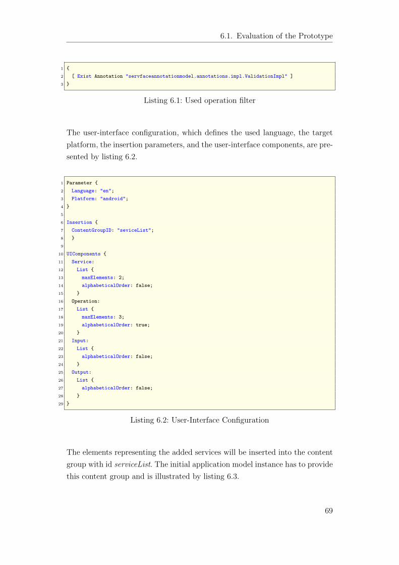
6.1. Evaluation of the Prototype
1 {
2 [ Exist Annotation "servfaceannotationmodel.annotations.impl.ValidationImpl" ]
3 }
Listing 6.1: Used operation filter
The user-interface configuration, which defines the used language, the target
platform, the insertion parameters, and the user-interface components, are pre-
sented by listing 6.2.
1 Parameter {
2 Language: "en";
3 Platform: "android";
4 }
5
6 Insertion {
7 ContentGroupID: "seviceList";
8 }
9
10 UIComponents {
11 Service:
12 List {
13 maxElements: 2;
14 alphabeticalOrder: false;
15 }
16 Operation:
17 List {
18 maxElements: 3;
19 alphabeticalOrder: true;
20 }
21 Input:
22 List {
23 alphabeticalOrder: false;
24 }
25 Output:
26 List {
27 alphabeticalOrder: false;
28 }
29 }
Listing 6.2: User-Interface Configuration
The elements representing the added services will be inserted into the content
group with id serviceList. The initial application model instance has to provide
this content group and is illustrated by listing 6.3.
69
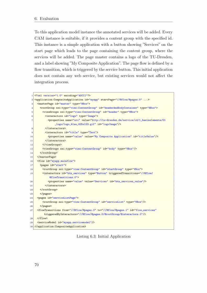
6. Evaluation
To this application model instance the annotated services will be added. Every
CAM instance is suitable, if it provides a content group with the specified id.
This instance is a simple application with a button showing ”Services” on the
start page which leads to the page containing the content group, where the
services will be added. The page master contains a logo of the TU-Dresden,
and a label showing ”My Composite Application”. The page flow is defined by a
flow transition, which is triggered by the service button. This initial application
does not contain any web service, but existing services would not affect the
integration process.
1 <?xml version="1.0" encoding="ASCII"?>
2 <application:CompositeApplication id="myapp" startPage="//@flow/@pages.0" ...>
3 <masterPage id="master" type="HBox">
4 <rootGroup xsi:type="view:ContentGroup" id="headerAndBodyContainer" type="HBox">
5 <viewGroups xsi:type="view:ContentGroup" id="header" type="HBox">
6 <interactors id="logo" type="Image">
7 <properties name="src" value="http://tu-dresden.de/service/cd/1_basiselemente/01
_logo/logo_blau_425x123.gif" id="logoImage"/>
8 </interactors>
9 <interactors id="title" type="Text">
10 <properties name="value" value="My Composite Application" id="titleValue"/>
11 </interactors>
12 </viewGroups>
13 <viewGroups xsi:type="view:ContentGroup" id="body" type="VBox"/>
14 </rootGroup>
15 </masterPage>
16 <flow id="myapp.mainflow">
17 <pages id="start">
18 <rootGroup xsi:type="view:ContentGroup" id="startGroup" type="VBox">
19 <interactors id="btn_services" type="Button" triggeredTransitions="//@flow/
@flowTransitions.0">
20 <properties name="value" value="Services" id="btn_services_value"/>
21 </interactors>
22 </rootGroup>
23 </pages>
24 <pages id="serviceListPage">
25 <rootGroup xsi:type="view:ContentGroup" id="serviceList" type="VBox"/>
26 </pages>
27 <flowTransitions from="//@flow/@pages.0" to="//@flow/@pages.1" id="flow_services"
triggeredByInteractors="//@flow/@pages.0/@rootGroup/@interactors.0"/>
28 </flow>
29 <serviceModel id="myapp.servicemodel"/>
30 </application:CompositeApplication>
Listing 6.3: Initial Application
70
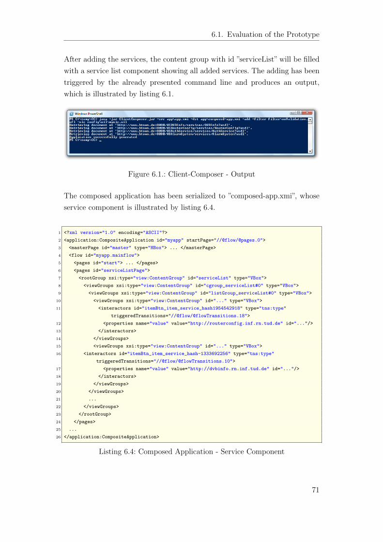
6.1. Evaluation of the Prototype
After adding the services, the content group with id ”serviceList” will be filled
with a service list component showing all added services. The adding has been
triggered by the already presented command line and produces an output,
which is illustrated by listing 6.1.
Figure 6.1.: Client-Composer - Output
The composed application has been serialized to ”composed-app.xmi”, whose
service component is illustrated by listing 6.4.
1 <?xml version="1.0" encoding="ASCII"?>
2 <application:CompositeApplication id="myapp" startPage="//@flow/@pages.0">
3 <masterPage id="master" type="HBox"> ... </masterPage>
4 <flow id="myapp.mainflow">
5 <pages id="start"> ... </pages>
6 <pages id="serviceListPage">
7 <rootGroup xsi:type="view:ContentGroup" id="serviceList" type="VBox">
8 <viewGroups xsi:type="view:ContentGroup" id="cgroup_serviceList#0" type="VBox">
9 <viewGroups xsi:type="view:ContentGroup" id="listGroup_serviceList#0" type="VBox">
10 <viewGroups xsi:type="view:ContentGroup" id="..." type="VBox">
11 <interactors id="itemBtn_item_service_hash1954542918" type="tns:type"
triggeredTransitions="//@flow/@flowTransitions.18">
12 <properties name="value" value="http://routerconfig.inf.rn.tud.de" id="..."/>
13 </interactors>
14 </viewGroups>
15 <viewGroups xsi:type="view:ContentGroup" id="..." type="VBox">
16 <interactors id="itemBtn_item_service_hash-1333692256" type="tns:type"
triggeredTransitions="//@flow/@flowTransitions.10">
17 <properties name="value" value="http://dvbinfo.rn.inf.tud.de" id="..."/>
18 </interactors>
19 </viewGroups>
20 </viewGroups>
21 ...
22 </viewGroups>
23 </rootGroup>
24 </pages>
25 ...
26 </application:CompositeApplication>
Listing 6.4: Composed Application - Service Component
71
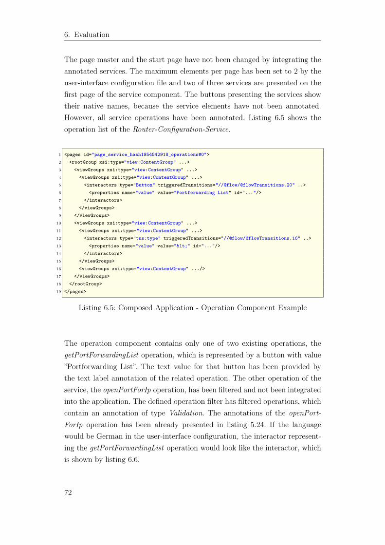
6. Evaluation
The page master and the start page have not been changed by integrating the
annotated services. The maximum elements per page has been set to 2 by the
user-interface configuration file and two of three services are presented on the
first page of the service component. The buttons presenting the services show
their native names, because the service elements have not been annotated.
However, all service operations have been annotated. Listing 6.5 shows the
operation list of the Router-Configuration-Service.
1 <pages id="page_service_hash1954542918_operations#0">
2 <rootGroup xsi:type="view:ContentGroup" ...>
3 <viewGroups xsi:type="view:ContentGroup" ...>
4 <viewGroups xsi:type="view:ContentGroup" ...>
5 <interactors type="Button" triggeredTransitions="//@flow/@flowTransitions.20" ..>
6 <properties name="value" value="Portforwarding List" id="..."/>
7 </interactors>
8 </viewGroups>
9 </viewGroups>
10 <viewGroups xsi:type="view:ContentGroup" ...>
11 <viewGroups xsi:type="view:ContentGroup" ...>
12 <interactors type="tns:type" triggeredTransitions="//@flow/@flowTransitions.16" ..>
13 <properties name="value" value="<" id="..."/>
14 </interactors>
15 </viewGroups>
16 <viewGroups xsi:type="view:ContentGroup" .../>
17 </viewGroups>
18 </rootGroup>
19 </pages>
Listing 6.5: Composed Application - Operation Component Example
The operation component contains only one of two existing operations, the
getPortForwardingList operation, which is represented by a button with value
”Portforwarding List”. The text value for that button has been provided by
the text label annotation of the related operation. The other operation of the
service, the openPortForIp operation, has been filtered and not been integrated
into the application. The defined operation filter has filtered operations, which
contain an annotation of type Validation. The annotations of the openPort-
ForIp operation has been already presented in listing 5.24. If the language
would be German in the user-interface configuration, the interactor represent-
ing the getPortForwardingList operation would look like the interactor, which
is shown by listing 6.6.
72
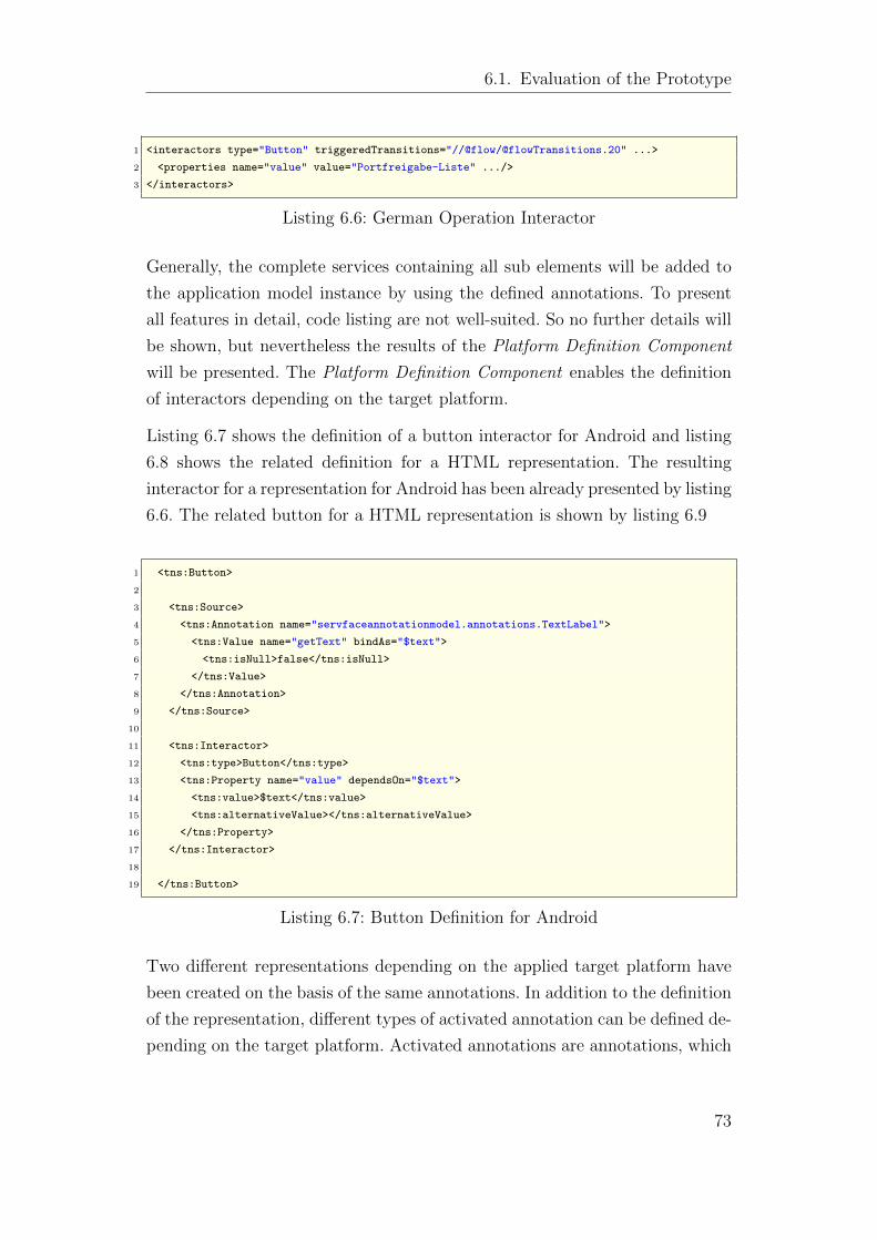
6.1. Evaluation of the Prototype
1 <interactors type="Button" triggeredTransitions="//@flow/@flowTransitions.20" ...>
2 <properties name="value" value="Portfreigabe-Liste" .../>
3 </interactors>
Listing 6.6: German Operation Interactor
Generally, the complete services containing all sub elements will be added to
the application model instance by using the defined annotations. To present
all features in detail, code listing are not well-suited. So no further details will
be shown, but nevertheless the results of the Platform Definition Component
will be presented. The Platform Definition Component enables the definition
of interactors depending on the target platform.
Listing 6.7 shows the definition of a button interactor for Android and listing
6.8 shows the related definition for a HTML representation. The resulting
interactor for a representation for Android has been already presented by listing
6.6. The related button for a HTML representation is shown by listing 6.9
1 <tns:Button>
2
3 <tns:Source>
4 <tns:Annotation name="servfaceannotationmodel.annotations.TextLabel">
5 <tns:Value name="getText" bindAs="$text">
6 <tns:isNull>false</tns:isNull>
7 </tns:Value>
8 </tns:Annotation>
9 </tns:Source>
10
11 <tns:Interactor>
12 <tns:type>Button</tns:type>
13 <tns:Property name="value" dependsOn="$text">
14 <tns:value>$text</tns:value>
15 <tns:alternativeValue></tns:alternativeValue>
16 </tns:Property>
17 </tns:Interactor>
18
19 </tns:Button>
Listing 6.7: Button Definition for Android
Two different representations depending on the applied target platform have
been created on the basis of the same annotations. In addition to the definition
of the representation, different types of activated annotation can be defined de-
pending on the target platform. Activated annotations are annotations, which
73
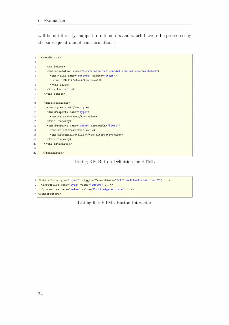
6. Evaluation
will be not directly mapped to interactors and which have to be processed by
the subsequent model transformations.
1 <tns:Button>
2
3 <tns:Source>
4 <tns:Annotation name="servfaceannotationmodel.annotations.TextLabel">
5 <tns:Value name="getText" bindAs="$text">
6 <tns:isNull>false</tns:isNull>
7 </tns:Value>
8 </tns:Annotation>
9 </tns:Source>
10
11 <tns:Interactor>
12 <tns:type>input</tns:type>
13 <tns:Property name="type">
14 <tns:value>button</tns:value>
15 </tns:Property>
16 <tns:Property name="value" dependsOn="$text">
17 <tns:value>$text</tns:value>
18 <tns:alternativeValue></tns:alternativeValue>
19 </tns:Property>
20 </tns:Interactor>
21
22 </tns:Button>
Listing 6.8: Button Definition for HTML
1 <interactors type="input" triggeredTransitions="//@flow/@flowTransitions.20" ...>
2 <properties name="type" value="button" .../>
3 <properties name="value" value="Portfreigabe-Liste" .../>
4 </interactors>
Listing 6.9: HTML Button Interactor
74
6.2. Evaluation of the Requirements
6.2. Evaluation of the Requirements
In the following, the requirements of chapter Analyses(2.2) will be evaluated
separately.
/r1: Ad-hoc integration of annotated web services to instances of the
application meta-model
The system has been implemented in a way, which enables the adding of an
annotated service to an existing application model instance. Already contained
services are updated. The related annotations and service descriptions are
parsed at runtime. In this way, an ad-hoc integration has been realized and
the main functional requirement has been achieved.
/r2: Parameterization of the integration
By using the user-interface configuration language UIL, this requirement has
been fulfilled. It is possible to define insertion parameters, which specify the
point at which the services are inserted into the instance. Also the language
and the target platform have to be defined and the created user-interface com-
ponents can be parameterized by defining the maximum number of elements
per page and applying an alphabetical order or not.
/r3: Integration of selected ServFace Annotations
This requirement has been met, as annotations were processed for the gener-
ation of the user interface. The use of annotations facilitates the creation of
certain user interface elements as demonstrated by the example (6.1). The fol-
lowing annotations have been implemented: TextLabel, MandatoryField, Enum,
Validation, Suggestion, Authentication, Group, SynchronousUpdate.
/r4: Filtering of web service operation
The developed operation filter language OFL and the related OFL-Interpreter
fulfill this requirement. It is possible to filter operations depending on their
name, their operation parameters, and their associated annotations. The filter
language can easily be extended to other filters.
75
6. Evaluation
/r5: Support of several target platforms
To achieve this requirement, the Platform Definition Component has been de-
veloped, which enables the definition of the representation of the user-interface
interactors depending on the target platform. Several annotations and data
types can be defined, which lead to different representations on different plat-
forms.
/r6: Generality
The generator can be applied to any annotated web service which conforms
to the WSDL specification 1.1. To ensure this requirement, the approved Web
Services Description Language for Java Toolkit (WSDL4J) was chosen to build
the basis of the integrated WSDL-Parser. For the notation of the annotations
the ServFace Annotations Model 1.1. served as a template with the restriction
that just some selected annotations have been implemented exemplarily.
/r7: Modularity
The requirement of modularity has been ensured by the separation of the
generator into the three parts WSDL-Parser, Annotation-Parser and Model-
Generator. The Operation-Filter Component and the Platform Definition Com-
ponent are reusable parts of the Model-Generator.
6.3. Comparison of the different Approaches
As already presented in the State-of-the-Art analysis (3.1.3), the author of
[Mar09] uses another approach for ad-hoc integration of annotated services. In
this section, the different approaches will be compared to each other in regards
of their advantages and disadvantages. In a direct comparison, the efficiency
of the respective prototypes will be reviewed and evaluated on basis of an
efficiency measurement. In a subsequent comparison, the qualitative differences
of the whole approaches will be evaluated and presented.
76
6.3. Comparison of the different Approaches
6.3.1. Efficiency Measurement
First, it should be mentioned that a direct comparison of two executable appli-
cations is not possible due the lack of a required model transformation for the
model driven approach, which would transform the resulting model instance
to an Android application. Due to this fact, the comparison will be restricted
to the parts of parsing the description documents and processing the data to
create UI elements representing the annotated services elements. For the mea-
surement, the logger of the java.util.logging19 package has been used, which
provides core logging facilities and is available for the Android platform as
well. The different prototypes have been executed in their respective environ-
ments. So the values for the Android-Interpreter have been determined on a
HTC Magic20 device with UTMS network access, and the values for the Model-
Generator on a server environment with broadband network access running
SunOS 5.10 21.
In a first comparison, the duration of parsing the service description formats,
and the creation of the UI elements have been measured. The integration of the
DVB-Info-Service (see section 2.1) has been used as scenario for this measure-
ment. A total of ten measurements have been taken to determine the average
duration and their standard deviation of several tasks. Table 6.1 shows the
measured values for the integration of the DVB-Info Service.
Android-Interpreter Model-Generator
Task duration σ duration σ
WSDL-Parsing 1398 ms 221 ms 141 ms 30 msAnnotation-Parsing 794 ms 43 ms 109 ms 9 msUI-Creation 116 ms 3 ms 1.8 ms 0.45 ms
Table 6.1.: Integration of the DVB-Info Service
The DVB-Info-Service consists of 5 service operations with totally 9 operation
elements, which have been annotated by 40 annotations. Three different tasks
have been determined, which have to be performed during the integration.
19http://java.sun.com/j2se/1.4.2/docs/api/java/util/logging/package-summary.htmlhttp://developer.android.com/reference/java/util/logging/package-summary.html
20http://www.htc.com/www/product/magic/overview.html21http://www.sun.com/software/solaris/index.jsp
77
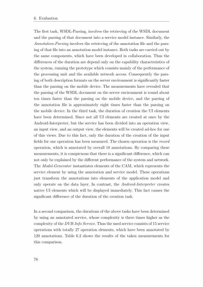
6. Evaluation
The first task, WSDL-Parsing, involves the retrieving of the WSDL document
and the parsing of that document into a service model instance. Similarly, the
Annotation-Parsing involves the retrieving of the annotation file and the pars-
ing of that file into an annotation model instance. Both tasks are carried out by
the same components, which have been developed in collaboration. Thus the
differences of the duration are depend only on the capability characteristics of
the system, running the prototype which consists mainly of the performance of
the processing unit and the available network access. Consequently the pars-
ing of both description formats on the server environment is significantly faster
than the parsing on the mobile device. The measurements have revealed that
the parsing of the WSDL document on the server environment is round about
ten times faster than the parsing on the mobile device, and the parsing of
the annotation file is approximately eight times faster than the parsing on
the mobile device. In the third task, the duration of creation the UI elements
have been determined. Since not all UI elements are created at once by the
Android-Interpreter, but the service has been divided into an operation view,
an input view, and an output view, the elements will be created ad-hoc for one
of this views. Due to this fact, only the duration of the creation of the input
fields for one operation has been measured. The chosen operation is the record
operation, which is annotated by overall 18 annotations. By comparing these
measurements, it is conspicuous that there is a significant difference, which can
not only be explained by the different performance of the system and network.
The Model-Generator instantiates elements of the CAM, which represents the
service element by using the annotation and service model. These operations
just transform the annotations into elements of the application model and
only operate on the data layer. In contrast, the Android-Interpreter creates
native UI elements which will be displayed immediately. This fact causes the
significant difference of the duration of the creation task.
In a second comparison, the durations of the above tasks have been determined
by using an annotated service, whose complexity is three times higher as the
complexity of the DVB-Info Service. Thus the used service consists of 15 service
operations with totally 27 operation elements, which have been annotated by
120 annotations. Table 6.2 shows the results of the taken measurements for
this comparison.
78
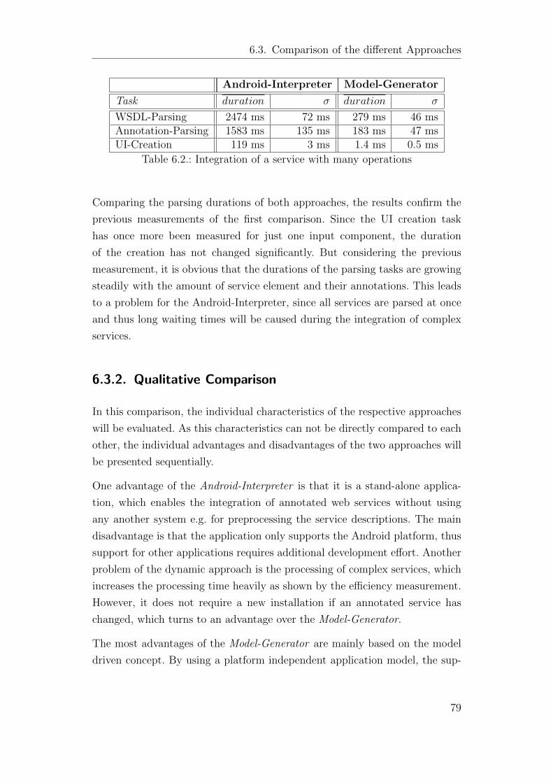
6.3. Comparison of the different Approaches
Android-Interpreter Model-Generator
Task duration σ duration σ
WSDL-Parsing 2474 ms 72 ms 279 ms 46 msAnnotation-Parsing 1583 ms 135 ms 183 ms 47 msUI-Creation 119 ms 3 ms 1.4 ms 0.5 ms
Table 6.2.: Integration of a service with many operations
Comparing the parsing durations of both approaches, the results confirm the
previous measurements of the first comparison. Since the UI creation task
has once more been measured for just one input component, the duration
of the creation has not changed significantly. But considering the previous
measurement, it is obvious that the durations of the parsing tasks are growing
steadily with the amount of service element and their annotations. This leads
to a problem for the Android-Interpreter, since all services are parsed at once
and thus long waiting times will be caused during the integration of complex
services.
6.3.2. Qualitative Comparison
In this comparison, the individual characteristics of the respective approaches
will be evaluated. As this characteristics can not be directly compared to each
other, the individual advantages and disadvantages of the two approaches will
be presented sequentially.
One advantage of the Android-Interpreter is that it is a stand-alone applica-
tion, which enables the integration of annotated web services without using
any another system e.g. for preprocessing the service descriptions. The main
disadvantage is that the application only supports the Android platform, thus
support for other applications requires additional development effort. Another
problem of the dynamic approach is the processing of complex services, which
increases the processing time heavily as shown by the efficiency measurement.
However, it does not require a new installation if an annotated service has
changed, which turns to an advantage over the Model-Generator.
The most advantages of the Model-Generator are mainly based on the model
driven concept. By using a platform independent application model, the sup-
79
6. Evaluation
port of various target platform is possible by providing the respective model
transformations. This requires, especially for the Client-Composer scenario,
always a new generation and consequently installation of the composed service
application, which is a disadvantage compared to the Android-Interpreter. But
a positive aspect is the support of filtering service operations by the use of the
filter language OFL. The UI can be parametrized by the configuration language
UIL as well. These techniques shall be suitable for tool support at design time,
which have to be investigated in a further process.
Essentially, both approaches have their advantages and disadvantages. A com-
parison of two Android applications was not possible due to the lack of needed
model transformations, which would have allowed a more detailed compari-
son.
80
7. Summary and Future Work
The main objective of this elaboration was the investigation of a process for
an ad-hoc integration of annotated services into instances of a meta-model
of interactive service based applications. In a first analysis, the requirements
for a system for an ad-hoc integration have been determined and a scenario
has been presented, which requires such an integration. After a state of the
art analysis in this context, already existing approaches have been presented
and differentiated related to this approach. The results of that analysis have
shown that the most approaches do not support a service composition or do
not allow an automatic ad-hoc integration. Starting from this, a concept has
been presented, which allows an ad-hoc integration of annotated services into
instances of a meta-model of interactive service-based applications. This con-
cept has been implemented prototypically. This prototype has been evaluated
regarding the founded requirement. Beside this evaluation, the approach of
[Mar09] has been closely examined and has been compared to the one pre-
sented in this thesis in regards of their advantages and disadvantages in the
evaluation chapter (6.3). In conclusion, a prototype has been developed, which
supports an ad-hoc integration. This integration can be parametrized relating
to the creation of the user-interface. An operation filter has been developed,
which enables the filtering of the service operation depending on their service
descriptions and annotations.
The model transformations transforming the CAM into a executable appli-
cation are currently under development by the the ServFace Project. This
transformation could be used in a further process to evaluate the developed
prototype in a better way. The concepts of the investigated process could also
be adopted to design-time processes. Especially the user-interface configura-
tion and the operation filter shall be suitable for tool support at design time,
which also have to be investigated in a further process. Also the platform def-
81

7. Summary and Future Work
inition can be refined in a further process. Currently, unbounded data types
can not be defined, to create list views for example.
82
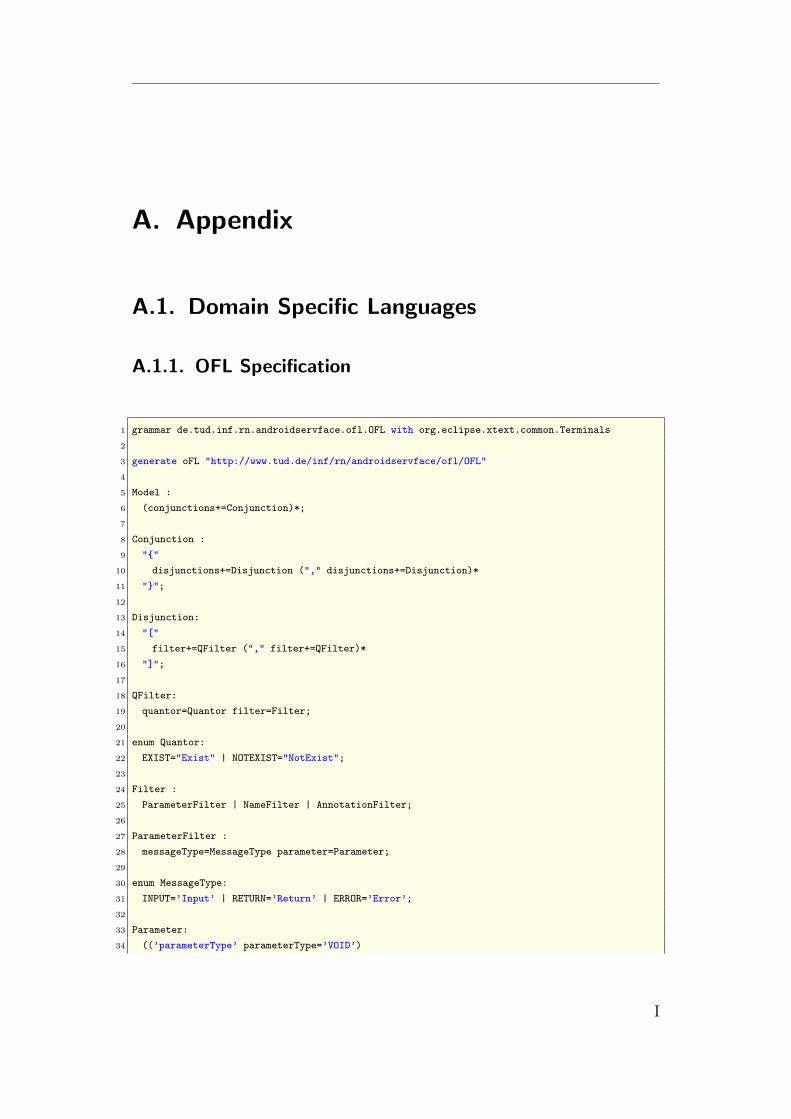
A. Appendix
A.1. Domain Specific Languages
A.1.1. OFL Specification
1 grammar de.tud.inf.rn.androidservface.ofl.OFL with org.eclipse.xtext.common.Terminals
2
3 generate oFL "http://www.tud.de/inf/rn/androidservface/ofl/OFL"
4
5 Model :
6 (conjunctions+=Conjunction)*;
7
8 Conjunction :
9 "{"
10 disjunctions+=Disjunction ("," disjunctions+=Disjunction)*
11 "}";
12
13 Disjunction:
14 "["
15 filter+=QFilter ("," filter+=QFilter)*
16 "]";
17
18 QFilter:
19 quantor=Quantor filter=Filter;
20
21 enum Quantor:
22 EXIST="Exist" | NOTEXIST="NotExist";
23
24 Filter :
25 ParameterFilter | NameFilter | AnnotationFilter;
26
27 ParameterFilter :
28 messageType=MessageType parameter=Parameter;
29
30 enum MessageType:
31 INPUT=’Input’ | RETURN=’Return’ | ERROR=’Error’;
32
33 Parameter:
34 ((’parameterType’ parameterType=’VOID’)
I
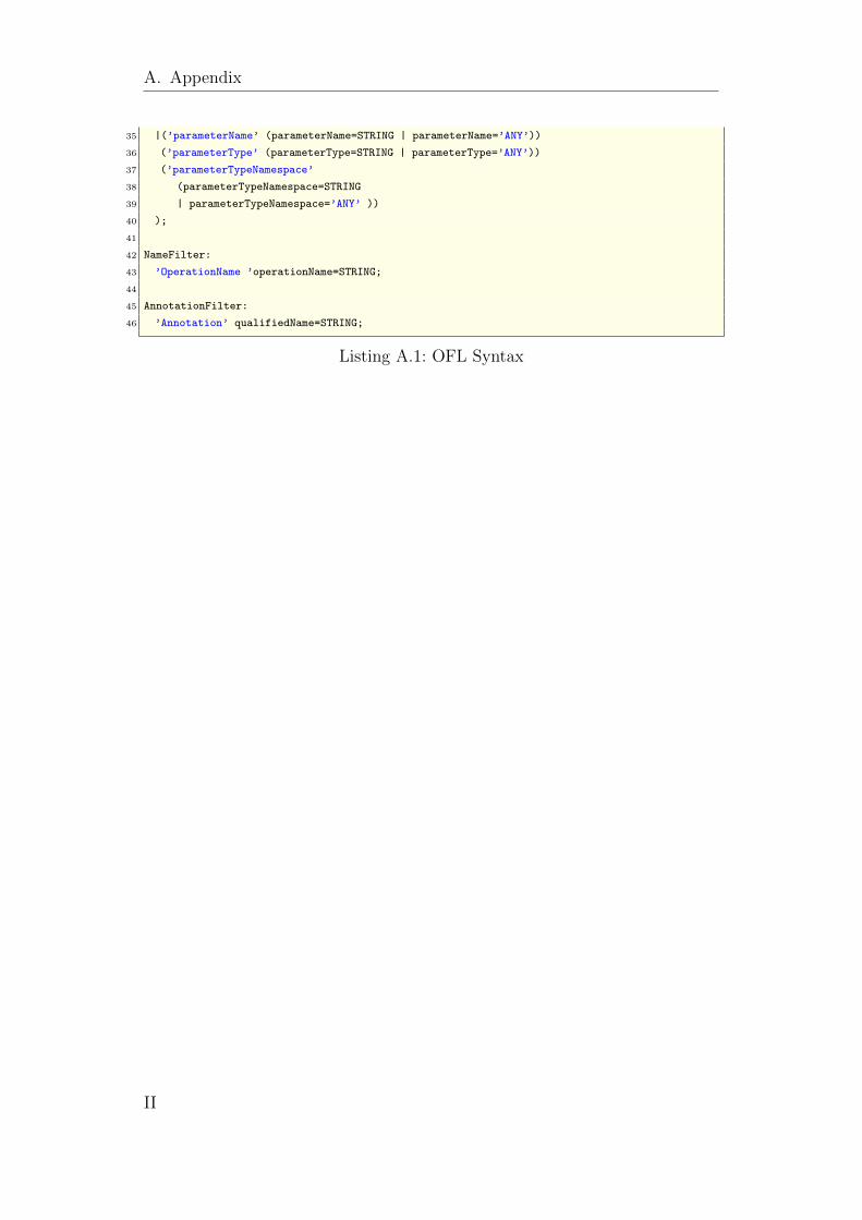
A. Appendix
35 |(’parameterName’ (parameterName=STRING | parameterName=’ANY’))
36 (’parameterType’ (parameterType=STRING | parameterType=’ANY’))
37 (’parameterTypeNamespace’
38 (parameterTypeNamespace=STRING
39 | parameterTypeNamespace=’ANY’ ))
40 );
41
42 NameFilter:
43 ’OperationName ’operationName=STRING;
44
45 AnnotationFilter:
46 ’Annotation’ qualifiedName=STRING;
Listing A.1: OFL Syntax
II

A.1. Domain Specific Languages
A.1.2. UIL Specification
1 grammar de.tud.inf.rn.androidservface.UIl with org.eclipse.xtext.common.Terminals
2
3 generate uIl "http://www.tud.de/inf/rn/androidservface/UIl"
4
5 Model :
6 ’Parameter’ ’{’(parameter=Parameter)’}’
7 ’Insertion’ ’{’ insertion=InsertionParameter ’}’
8 ’UIComponents’ ’{’(uiComponents=UserInterface)’}’;
9
10 Parameter:
11 ’Language’’:’language=STRING’;’
12 ’Platform’’:’platform=STRING’;’;
13
14 InsertionParameter:
15 ’ContentGroupID’’:’contentGroupId=STRING’;’
16 (’PreviousPageID’’:’previousPageID=STRING’;’)?;
17
18 UserInterface:
19 ’Service’’:’serviceComponent=UIComponent
20 ’Operation’’:’operationComponent=UIComponent
21 ’Input’’:’inputComponent=UIComponent
22 ’Output’’:’outputComponent=UIComponent;
23
24 UIComponent:
25 ListComponent;
26
27 ListComponent:
28 ’List’’{’
29 ’maxElements’’:’maxElements=INT’;’
30 ’alphabeticalOrder’’:’alphabeticalOrder=BooleanType’;’
31 ’}’;
32
33 //basic types
34 enum BooleanType:
35 TRUE=’true’ | FALSE=’false’;
Listing A.2: UIL Syntax
III
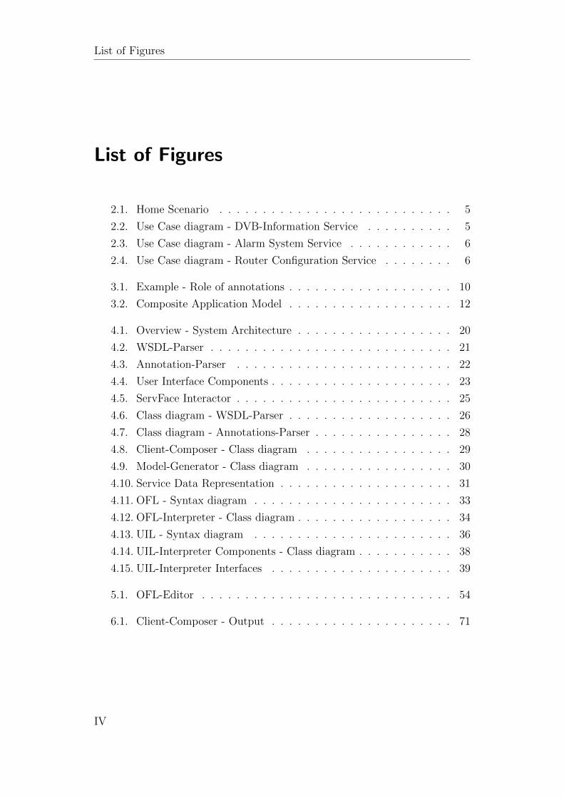
List of Figures
List of Figures
2.1. Home Scenario . . . . . . . . . . . . . . . . . . . . . . . . . . . 5
2.2. Use Case diagram - DVB-Information Service . . . . . . . . . . 5
2.3. Use Case diagram - Alarm System Service . . . . . . . . . . . . 6
2.4. Use Case diagram - Router Configuration Service . . . . . . . . 6
3.1. Example - Role of annotations . . . . . . . . . . . . . . . . . . . 10
3.2. Composite Application Model . . . . . . . . . . . . . . . . . . . 12
4.1. Overview - System Architecture . . . . . . . . . . . . . . . . . . 20
4.2. WSDL-Parser . . . . . . . . . . . . . . . . . . . . . . . . . . . . 21
4.3. Annotation-Parser . . . . . . . . . . . . . . . . . . . . . . . . . 22
4.4. User Interface Components . . . . . . . . . . . . . . . . . . . . . 23
4.5. ServFace Interactor . . . . . . . . . . . . . . . . . . . . . . . . . 25
4.6. Class diagram - WSDL-Parser . . . . . . . . . . . . . . . . . . . 26
4.7. Class diagram - Annotations-Parser . . . . . . . . . . . . . . . . 28
4.8. Client-Composer - Class diagram . . . . . . . . . . . . . . . . . 29
4.9. Model-Generator - Class diagram . . . . . . . . . . . . . . . . . 30
4.10. Service Data Representation . . . . . . . . . . . . . . . . . . . . 31
4.11. OFL - Syntax diagram . . . . . . . . . . . . . . . . . . . . . . . 33
4.12. OFL-Interpreter - Class diagram . . . . . . . . . . . . . . . . . . 34
4.13. UIL - Syntax diagram . . . . . . . . . . . . . . . . . . . . . . . 36
4.14. UIL-Interpreter Components - Class diagram . . . . . . . . . . . 38
4.15. UIL-Interpreter Interfaces . . . . . . . . . . . . . . . . . . . . . 39
5.1. OFL-Editor . . . . . . . . . . . . . . . . . . . . . . . . . . . . . 54
6.1. Client-Composer - Output . . . . . . . . . . . . . . . . . . . . . 71
IV
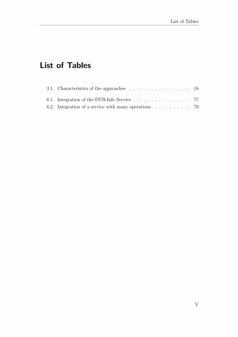
List of Tables
List of Tables
3.1. Characteristics of the approaches . . . . . . . . . . . . . . . . . 18
6.1. Integration of the DVB-Info Service . . . . . . . . . . . . . . . . 77
6.2. Integration of a service with many operations . . . . . . . . . . 79
V
Listings
Listings
4.1. OFL - Example . . . . . . . . . . . . . . . . . . . . . . . . . . . 34
4.2. Standard Configuration . . . . . . . . . . . . . . . . . . . . . . . 36
4.3. Platform Definition Example . . . . . . . . . . . . . . . . . . . . 40
5.1. Authentication . . . . . . . . . . . . . . . . . . . . . . . . . . . 43
5.2. Use of WSDL-Parser . . . . . . . . . . . . . . . . . . . . . . . . 44
5.3. Example Annotations . . . . . . . . . . . . . . . . . . . . . . . . 45
5.4. Object creation by Factories . . . . . . . . . . . . . . . . . . . . 46
5.5. Client Composer - Help Message . . . . . . . . . . . . . . . . . . 47
5.6. Client Composer . . . . . . . . . . . . . . . . . . . . . . . . . . 48
5.7. Directory Service Handler . . . . . . . . . . . . . . . . . . . . . 49
5.8. Client-Composer Settings . . . . . . . . . . . . . . . . . . . . . 50
5.9. CAMGenerator - loadApplication . . . . . . . . . . . . . . . . . 51
5.10. Application - Constructor . . . . . . . . . . . . . . . . . . . . . 52
5.11. Client-Composer - Adding of an operation filter . . . . . . . . . 52
5.12. Adding of annotated services filter . . . . . . . . . . . . . . . . . 53
5.13. OFLInterpreter . . . . . . . . . . . . . . . . . . . . . . . . . . . 55
5.14. ConjunctionInterpreter - isFiltered method . . . . . . . . . . . . 56
5.15. NameFilterInterpreter - isFiltered method . . . . . . . . . . . . 56
5.16. Application - addAnnotatedService method . . . . . . . . . . . . 57
5.17. AnnotatedService - filterOperations method . . . . . . . . . . . 58
5.18. AnnotatedService - initComponents method . . . . . . . . . . . 59
5.19. AbstractComponentInterpreter - init method . . . . . . . . . . . 60
5.20. Page ID of the first page of a Service-Component . . . . . . . . 61
5.21. AbstractListInterpreter - addItem method . . . . . . . . . . . . 62
5.22. Configuration example - 3 elements per page in alph. order . . . 62
5.23. Configuration example - 2 elements per page in no alph. order . 63
5.24. Annotations for IP-Adress input . . . . . . . . . . . . . . . . . . 64
VI
Listings
5.25. Definition of the text label . . . . . . . . . . . . . . . . . . . . . 64
5.26. Definition of the text field . . . . . . . . . . . . . . . . . . . . . 65
5.27. Interactor Creation . . . . . . . . . . . . . . . . . . . . . . . . . 66
5.28. IP-Adress - Text Label . . . . . . . . . . . . . . . . . . . . . . . 66
5.29. IP-Adress - Input Text Field . . . . . . . . . . . . . . . . . . . . 66
6.1. Used operation filter . . . . . . . . . . . . . . . . . . . . . . . . 69
6.2. User-Interface Configuration . . . . . . . . . . . . . . . . . . . . 69
6.3. Initial Application . . . . . . . . . . . . . . . . . . . . . . . . . 70
6.4. Composed Application - Service Component . . . . . . . . . . . 71
6.5. Composed Application - Operation Component Example . . . . 72
6.6. German Operation Interactor . . . . . . . . . . . . . . . . . . . 73
6.7. Button Definition for Android . . . . . . . . . . . . . . . . . . . 73
6.8. Button Definition for HTML . . . . . . . . . . . . . . . . . . . . 74
6.9. HTML Button Interactor . . . . . . . . . . . . . . . . . . . . . . 74
A.1. OFL Syntax . . . . . . . . . . . . . . . . . . . . . . . . . . . . . I
A.2. UIL Syntax . . . . . . . . . . . . . . . . . . . . . . . . . . . . . III
VII
Bibliography
Bibliography
FJN+09 Marius Feldmann, Jordan Janeiro, Tobias Nestler, Gerald Hub-
sch, Uwe Jugel, Andre Preussner, and Alexander Schill. An inte-
grated approach for creating service-based interactive applications.
In INTERACT ’09: Proceedings of the 12th IFIP TC 13 Interna-
tional Conference on Human-Computer Interaction, pages 896–899,
Berlin, Heidelberg, 2009. Springer-Verlag.
FNM+09 M. Feldmann, T. Nestler, K. Muthmann, U. Jugel, G. Hubsch, and
A. Schill. Overview of an end-user enabled model-driven devel-
opment approach for interactive applications based on annotated
services. In WEWST ’09: Proceedings of the 4th Workshop on
Emerging Web Services Technology, pages 19–28, New York, NY,
USA, 2009. ACM.
HY07 Jiang He and I-Ling Yen. Adaptive user interface generation for
web services. In ICEBE ’07: Proceedings of the IEEE International
Conference on e-Business Engineering, pages 536–539, Washing-
ton, DC, USA, 2007. IEEE Computer Society.
KKM03 Michael Kassoff, Daishi Kato, and Waqar Mohsin. Creating guis
for web services. IEEE Internet Computing, 7(5):66–73, 2003.
Mar09 Felix Martens. Ad-hoc integration of annotated services for google
android. Großer beleg, Dresden University of Technologie, 2009.
PSS09 Fabio Paterno, Carmen Santoro, and Lucio Davide Spano. Support
for authoring service front-ends. In EICS ’09: Proceedings of the
1st ACM SIGCHI symposium on Engineering interactive computing
systems, pages 85–90, New York, NY, USA, 2009. ACM.
Spi06 Josef Spillner. Project dynvocation. Diploma, Dresden Technical
University, 2006.
VIII


![Action Plan MoU Drin Final Draft Annotated with comments ... · 1. Ad-hoc expert working group work prepares options for flood management [page 20] 5. Institutional strengthening](https://img.pdfslide.us/doc/110x75/5f17681aece63259e010af4d/action-plan-mou-drin-final-draft-annotated-with-comments-1-ad-hoc-expert-working.jpg)