Embed Size (px)
Citation preview

AD-A258 468AD IA258 46i ISpecial ReportS~CMU/SEI-92-SR-3
'__ ,______.o~ Mellon Urwercfy
- Software Engineering Institute
Joint Integrated AvionicsWorking Group (JIAWG)Object-Oriented DomainAnalysis Method (JODA)
Version 3.1
Robert Holibaugh
November 1992
TICLECTE
uEC 2 9 1992 L
Ths o11111111ýlhas been apprvaUmd sale: Its
AkA
92-32847
111 ""lDl IHl i HH9

Special ReportCMU/SEI-92-SR-3
November 1992
Joint Integrated Avionics Working Group (JIAWG)Object-Oriented Domain Analysis Method (JODA)
Version 3.1
Robert HolibaughJoint Integrated Avionics Working Group
Approved for public release.Distribution unlimited.
Software Engineering InstituteCarnegie Mellon University
Pittsburgh, Pennsylvania 15213
This technical report was prepared for the
SEI Joint Program OfficeESC/AVSHanscom AFB, MA 01731
The ideas and findings in this report should not be construed as an officialDoD position. It is published in the interest of scientific and technicalinformation exchange.
Review and Approval
This report has been reviewed and is approved for publication.
FOR THE COMMANDER
Thomas R. Miller, Lt Col, USAFSEI Joint Program Office
The Software Engineering Institute is sponsored by the U.S. Department of Defense.This report was funded by the U.S. Department of Defense.Copyright @ 1992 by Carnegie Mellon University.
This document is available through the Defense Technical Information Center. DTIC provides access to and transfer ofscientific and technical information for DoD personnel, DoD contractors and potential contractors, and other U.S. Governmentagency personnel and their contractors. To obtain a copy, please contact DTIC directly: Defense Technical InformationCenter, Attn: FORA, Cameron Station. Alexandria, VA 22304-6145.Copies of this document are also available through the National Technical Information Service. For information on ordering.please contact NTIS directly: National Technical Information Service, U.S. Department of Commerce, Springfield, VA 22161.
Copies of this document are also available from Research Access, Inc, 3400 Forbes Avenue, Suite 302, Pittsburgh, PA 15213.
Use of any trademarks in this report is not intended in any way to infringe on the rights of the tademark holder.

Table of Contents
1 Introduction 11.1 Purpose 11.2 Goals of Domain Analysis 21.3 Background 31.4 Relationship of Object-Oriented Analysis to JODA 41.5 Relationship of the JIAWG Method to the
Other Domain Analysis Methods 61.6 Organization of the Report 7
2 Context for Domain Analysis 92.1 Domain Engineering 10
2.1.1 Domain Analysis 112.1.2 Domain Implementation 142.1.3 Active Repository 15
2.2 Applications Engineering 152.2.1 DoD Standard Requirements 162.2.2 Model/Requirements Transformation 17
3 Domain Analysis Overview 213.1 Prepare Domain 223.2 Define Domain 233.3 Model Domain (OOA) 23
4 Domain Analysis Products 254.1 Domain Model 25
4.1.1 Requirements for the Domain Model 264.1.2 Class Specifications 274.1.3 Structure Diagrams 284.1.4 Subject Diagrams 284.1.5 Scenario Diagrams 294.1.6 Evolution of the Domain Model 29
4.2 Domain Definition 294.2.1 Requirements for the Domain Definition 304.2.2 Top-Level Subject Diagram 314.2.3 Top-Level Whole-Part Diagrams 324.2.4 Top-Level Generalization-Specialization Diagram 334.2.5 Domain Services 334.2.6 Domain Dependencies 344.2.7 Domain Glossary 354.2.8 Textual Description 35
4.3 DoD Standard Requirements 36
CMU/SEI-92-SR-3
5 Prepare Domain 375.1 Acquire Domain Expertise for the Analysis 385.2 Collect Source and Reference Material 38
6 Define Domain 416.1 Define Domain Context 416.2 Analyze Systems Artifacts 426.3 Identify Domain Structure 436.4 Analyze Scenarios with Top-Level Objects 436.5 Analyze Objects for External Dependencies 436.6 Document Domain Definition 446.7 Review and Update Domain Definition 44
6.7.1 Distribute Domain Definition for Review 456.7.2 Review Domain Definition with Domain Experts 456.7.3 Review Analysis Approach 46
7 Model Domain (OOA) 477.1 Examine Object Life-Histories and State-Event Response 487.2 Identify and Walk-Through Domain Scenarios 487.3 Abstract and Group Objects 487.4 Review and Update Domain Model 49
7.4.1 Distribute Domain Model for Review 517.4.2 Compare Domain Model with an Existing System 517.4.3 Review Domain Model with Domain Experts 517.4.4 Review Modeling Approach 52
8 Transition to Domain Implementation 538.1 Transition to Domain Imp~ementation 538.2 Relationship of Domain Analysis to DoD-STD-2167A 54
Appendix A Office Building ElevatorSystem Diagrams55
Appendix B Office Building Elevator System Specifications 65B.1 Specification Statement for the Office Building Elevator System 65B.2 Specification of Elevator Lobby Object of
Office Building Elevator System 66B.3 Elevator Specification for Office Building Elevator System 68B.4 Controller Specification for Office Building Elevator System 69B.5 Service Button Specification 70B.6 Open Doors Button Specification 70B.7 Status Indicator Specification 71B.8 Elevator Alarm Specification 72
CMU/SEI-92-SR-3

B.9 Door Specification for Office Building Elevator System 72B. 10 Elevator Lobby Access Door Specification 73B. 11 Elevator Arrival Bell Specification 74B. 12 Object Specification Template 75
Appendix C CYOOA Notation and Process 77C.1 CYOOA Notation 77C.2 Analysis Activities 81
Glossary 87
References 89
Accesio'n For
NTIS CRA&IDTtC •• F2
B y. .......................... ....... ... ..
DB t .. t. on. .
Availabioity Co(cs
J sp 8ecial
DTCC9-
CMU/SEI-92-SR-3jj

iv CMU/SEI-92-SR-3
List of Figures
Figure 2-1 Reuse Based Software Development 9Figure 2-2 Applications Engineering Based on Domain Engineering 13Figure 2-3 Relationship of the DoD Standard Requirements to the
Domain Model 16Figure 3-1 Domain Analysis Process 22Figure 4-1 Table of Adaptation Types 36Figure 5-1 Domain Preparation Process 37Figure 6-1 Domain Definition Process 42Figure 6-2 Domain Definition Review Process 45Figure 7-1 Domain Modeling Process 47Figure 7-2 Domain Model Review Process 50Figure A-1 Top Level Subject Diagram for the
Office Building Elevator System 55Figure A-2 Assembly Structure Where the Office Building
Elevator System is a Part 55Figure A-3 Top Level Assembly Structure of an Elevator System 56Figure A-4 Top Level Classification Structure of Elevator Systems 57Figure A-5 Second Level Subject Diagram of Elevator System 58Figure A-6 Door Classification Structures for the Building Elevator System 58Figure A-7 Status Indicators Classification Structures 59Figure A-8 Elevator Arrival Bell 59Figure A-9 Service Button Classification Structures 60Figure A-10 Elevator Lobby Classification Structures 61Figure A-11 Elevator Object Diagram for Office Building Elevator 62Figure A-12 Elevator Lobby Object Diagram for
Office Building Elevator System 63Figure A-13 Controller for the Office Building Elevator System 63Figure C-1 Class/Object Notation 77Figure C-2 Gen-Spec Diagram 79Figure C-3 Instance Connection Constraint Notion 80Figure C-4 Whole-Part Notation 81Figure C-5 Subject Notation 81
CMUISEI-92-SR-3 v

vi CMU/SEI-92-SR-3

Joint Integrated Avionics Working Group (JIAWG)Object-Oriented Domain Analysis (JODA) Method
Abstract: The Joint integrated Avionics Working Group (JIAWG) ReuseSubcommittee has initiatives in several areas to demonstrate that reuse caneffectively support the JIAWG programs, and the creation of reusable assets isan essential element of reuse. Domain analysis is the process that identifieswhat is reusable, how it can be structured, and how it can be used. This reportdescribes a method for domain analysis that is based on Coad and Yourdon'sObject Oriented Analysis. This method, the JIAWG Object-Oriented DomainAnalysis (JODA), includes several enhancements to the method of Coad andYourdon and produces a domain model to support asset creation and reuse.
1 Introduction
The Joint Integrated Avionics Working Group (JIAWG) is a Tri-Service effort mandated byCongress to exploit maturing technology to realize the economic, supportability, and interop-erability advantages of common avionics hardware and software. The JIAWG Reuse Subcom-mittee, which is part of the Software Task Group, has developed initiatives in several areas todemonstrate that software reuse can effectively support the JIAWG programs [A-12, the AirForce's Advanced Tactical Fighter (ATF), the Army's Ught Helicopter (LH), the Air Force's Ad-vanced Tactical Aircraft (AF ATA), the Navy's ATF (NATF), and A-12 Preplanned 3 ProductImprovement (P I)]. The Reuse Subcommittee initiatives are: domain analysis, contract incen-tives, standards to support reuse, and reuse libraries.
The JIAWG Reuse Subcommittee's domain analysis group has been chartered with:
"* selecting, defining, documenting, and refining a domain analysis method,
"* performing an example avionics domain analysis and documenting theresults, and
"* documenting the lessons learned from the domain analysis effort.
1.1 Purpose
The purpose of this report is to document the JIAWG Object-Oriented Domain Analysis (JODA(pronounced as if written "yoda")) method that could be used by the JIAWG programs fordomain analysis. This method has already been used by the JIAWG Reuse Subcommittee'sdomain analysis group to anaiyze an avionics domain, stores management. This method andthe results of the stores management analysis are intended as examples for the JIAWG Sys-tems Program Offices (SPO) and contractors. The Reuse Subcommittee domain analysiseffort is also Intended to demonstrate the effectiveness of domain analysis technology for avi-onics software.
CMU/SEI-92-SR-3 1
The approach presented in this document is only one of several views of a reuse life cycle.(For other examples, see references 14, 25, and 29.) This domain analysis method is basedon the object-oriented analysis (OOA) techniques and notation defined in Object-OrientedAnalysis by Coad and Yourdon [7,8], which we will refer to as CYOOA. In this document,CYOOA notation has been broadened to include: performance issues, scenarios for control-ling the objects, and rationales for how, when, where, and why to use the objects when build-ing systems. These additions were necessary since CYOOA was originally intended forrequirements analysis in the construction of a single system. CYOOA notation was enhancedto validate and demonstrate the effectiveness of object-oriented techniques to support domainanalysis.
We believe that software objects are more understandable, more adaptable, and less likely tochange than functions. Tactical aircraft will always carry bombs, so a bomb object will alwaysbe part of a Stores Management System. The functions needed to manage and deliver a bombwill change over time, but the software changes are restricted to the bomb object, making iteasier to adapt that object [5, 16]. Finally, the bomb object's functions are limited to the statedefined by the object thus making the object easier to understand and change, since the main-tainer need only understand the bomb object and not all of Stores Management. For these rea-sons, object-oriented techniques have been chosen instead of a functional approach. Ourdomain analysis goal is to represent the requirements with OOA notation in a domain modelthat can be used to produce object-oriented requirements, designs, code, and tests.
The office building elevator systems (OBE) example was specifically chosen to help illustratethe domain analysis method and concepts. (The OBE problem statement is given in AppendixB.1.) The OBE system that provides safe and equitable service for its passengers for somenumber of elevators that service several floors was chosen because:
"* the OBE is well understood by a large audience,
"* the OBE illustrates the concepts of the method,
"* the OBE illustrates the breadth and depth of even simple domains, and
"* a clear, concise problem description was readily available.
1.2 Goals of Domain Analysis
The goal of domain analysis is to define a domain model that can be used to produce reusablesoftware objects (RSO), especially reusable requirements. The information in the domainmodel is collected using CYOOA techniques. Domain analysis is part of the domain engineer-ing process that uses the domain model to define a reusable software architecture, to designreusable code (a more detailed level of design than architecture), and to define the structureof the domain. The domain structure is the organization of the parts as dominated by the gen-eral character of the whole [24]. The domain structure is defined by the CYOOA diagrams thatdefine the composition of the domain through whole-part diagrams and the variation in objectsusing generalization-specialization (gen-spec) diagrams. The objects are defined by their ser-vice and their attributes, while domain structure is defined though whole-part concepts, varia-
2 CMU/SEI-92-SR-3

tion in objects, services, attributes, and concepts, and the relationships between these objectsand concepts.
1.3 Background
Gilroy, et. al., conclude in their research that, "Domain analysis, when done right, is a signifi-cant undertaking yet prcduces a significant benefit [13]." At a high level, domain analysis is acombination of reverse engineering, knowledge extraction, knowledge representation, re-quirements forecasting, and technology forecasting. In domain analysis, the essential con-cepts are extracted, represented, and adapted for reuse. Knowledge extraction andrepresentation are used to establish a domain framework, while reverse engineering fills in thedetails and validates the framework. Technology forecasting and requirements forecastingtechniques are used to ensure the results remain viable while the investment in domain anal-ysis is recovered. Recent literature on reuse indicates that domain analysis is one of the firstactivities that should be performed during the engineering of reusable software [21,29]. Orga-nizations that have conducted domain analysis prior to creating reusable software compo-nents have shown greater success in reusability [18, 20]. Reusable components that areconstructed from the results of domain analysis capture the essential concepts required in thatdomain; thus, developers find them easier to include in new systems [28].
After reviewing the literature on domain analysis, the author recognized that the informationthat is commonly collected by domain analysis methods is essentially the same as that definedby the CYOOA notation. For two additional reasons, CYOOA was selected and enhanced tosupport our domain analysis needs. First, other domain analysis efforts use CYOOA notationin thair domain analysis products. Second, selecting a commercial analysis technique makestraining, tools, and consulting support readily available. There was one major difference be-tween CYOOA and other domain analysis representation techniques. The information thatwas being represented and organized using CYOOA notation was accessible, understand-able, and concise. Even though there is no consensus on what results to represent in domainanalysis, the core set of our needs is met by CYOOA.
After further examination of the CYOOA notation and method, another domain analysis effortwas identified that uses CYOOA for its domain model [29]. The Software Productivity Consor-tium (SPC) has made minor additions to the notation; for example, SPC has added a textualdiscussion of the variation in classes, a textual discussion of the occurrence of the number ofobjects, and a discussion of performance requirements on the overall system. Since CYOOAwas being used by other reuse efforts and had commercial acceptance, training, and tools,CYOOA techniques were chosen for extracting, organizing, and representing the domainmodel.
In typical Department of Defense (DoD) software development, only the requirements, de-signs, code, and test materials are usually recorded, and if domain knowledge is recorded, itis never delivered. The value of the domain knowledge that is acquired by the developer is fre-quently not even recognized, and therefore, it is not available for post deployment software
CMU/SEI-92-SR-3 3
support (PDSS). Since the JIAWG aircraft may be in the DoD inventory for as long as twentyyears, PDSS which is also concerned with change and variation is a major concern of the
JIAWG Systems Program Offices (SPO). PDSS includes two activities: first, correcting prob-
lems with the system, and second, making necessary enhancements. To locate and correct
systems problems, the maintainer must understand the system requirements, design, andcode. The organization of information collected during domain analysis supports identifying,locating, and correcting the problem, since the domain knowledge helps the maintainer under-
stand the what, how, when, where, and why for the system data and services. The second ma-
jor PDSS activity includes making changes or enhancements to the system.
The domain model contains the information that is necessary (but seldom available) for mak-ing changes or enhancements to an existing system. The domain model includes the rationalefor all domain services, attributes, and objects. In fact, a desired PDSS change or enhance-ment may already be in the model, and its inclusion in the system may be relatively simple.Domain analysis supports post deployment software support as well as reuse, because it cap-tures and anticipates change.
1.4 Relationship of Object-Oriented Analysis to JODA
Object-oriented analysis techniques are used to define the structure and capture require-ments, but Coad and Yourdon's Object-Oriented Analysis (CYOOA) is not the same as theJIAWG Object-Oriented Domain Analysis (JODA). JODA and CYOOA differ in both notationand process: JODA has enhanced the CYOOA notation and process. The specific areaswhere JODA and CYOOA differ are as follows:
" The problem statement's scope is fixed before starting CYOOA, but it is not
fixed in domain analysis.
" CYOOA notation addresses a single system while JODA notation addressesa family of systems.
" CYOOA notation does not include scenarios definitions that have beeninclude in JODA to define the use of the domain's visible services.
"* An abstraction activity that is not in CYOOA has been included in the analysisphase of JODA.
"* A scenario definition and walk-through activity has been added to themodeling phase of JODA.
The problem statement is fixed at the beginning of CYOOA while it changes after the begin-ning of the JODA process. CYOOA is a software requirements analysis technique [7,12] thathas the problem defined by System Design [8, 12] since CYOOA is intended to support thesoftware engineering process. Domain analysis receives input from the Business and Meth-odology Planning steps [17], but these steps do not define the domain or bound the problem.Domain analysis must define the domain in addition to identifying, locating, and collectingsource material.
4 CMU/SEI-92-SR-3
The second difference between CYOOA and JODA concerns the scope of the problem.CYOOA is intended to address the analysis of a single problem and does not have all the no-tation and techniques required for defining variation in the domain. These deficiencies do notprevent the use of CYOOA; rather, by adding to the notation, CYOOA can be enhanced tospecify a domain instead of a single problem. Since CYOOA allows for the inclusion of addi-tional notation, this can be done easily. For example, CYOOA does not contain a rationale fordescribing how, when, where, and why to select options, services, and instances. (Rationaleis necessary when the reuser must select between options in the domain.) Also, CYOOA no-tation does not contain a mechanism for defining requirements which range over multiple ob-jects and a mechanism for specifying real-time performance parameters. Additions have beendefined in JODA to specify these requirements.
CYOOA does not have notation for defining scenarios that are a series of object services thatproduce a larger capability such as the stores management services that a pilot uses to re-lease a bomb. Scenarios and their description are essential to domain and software require-ments analysis. While a users' manual will describe scenarios that use the system's services,there is no users' manual for domain analysis. Scenarios have been added to CYOOA to iden-tify high-level capabilities in the domain. Notation has also been added to define the rationalefor each whole-part relationship, instance connection, and gen-spec relationship.
JODA and CYOOA also differ in analysis technique. The JODA analysis technique is an ex-tension of CYOOA. The CYOOA analysis defines five activities, but the order of the activitiesis not fixed. (See Appendix C.) JODA does not prescribe an ordering, but it adds two additionalactivities: (1) identify and walk-through scenarios, and (2) abstract and group objects. CYOOAdoes not emphasize identifying scenarios or abstracting objects across systems.
The domain analysis team must identify, document, and simulate scenarios to validate the ob-jects and their relationships. One reason for including scenarios is that high-level services likedelivering a bomb are a combination of other domain services. These scenarios are importantfor a user to obtain a gestalt for the domain. The simulation of scenarios is a basic techniqueused by experts to develop systems [1]. In JODA, these scenarios are explicitly identified, de-fined, and simulated by the analysts. The identification and definition helps organize and clar-ify the domain requirements. The simulation validates the classes, attributes, and services thathave been specified. Scenarios help the domain analyst and the users to understand and ap-ply the results of domain analysis.
The process of abstracting domain analysis results is similar to but not the same as defininggen-spec structure. The abstraction process includes defining additional gen-spec structure,but it also includes identifying subjects (as in Figure A-5). This subject diagram provides anoverview of the objects and their relationships for OBE systems. These abstractions are partof the CYOOA notation, but abstraction is not applied so that the results cover several sys-tems. The merging of objects and services from similar systems into an abstract representa-tion supports an integrated view of the domain. This integrated view is the goal of the abstractand group objects activity of domain modeling. This goal is important because the user of the
CMU/SEI-92-SR-3 5
domain model can analyze the subjects and their associated objects on at a time. This helps
prevent confusion and reduces that amount of detail to an acceptable level. Another abstrac-
tion example is the definition of Doors in Appendix B.9. Three door types (elevator lobby, ele-
vator, and elevator rear doors) were defined during the initial pass through the domain. These
door had similar services, but the abstraction was not identified until after the CYOOA analysis
was complete. The classes Services Button (as was the style in CYOOA, all objects from the
OBE example in this document will be capitalized in the text to identify them) in Appendix B.5
and Status Indicator in Appendix B.7 were also identified during the emphasis on abstraction.
These abstractions have been useful for describing the domain especially at the high level.
Two activities have been added to CYOOA analysis: identifying and walking through domain
scenarios and abstracting and grouping objects. These additions enhance CYOOA to specifya family of systems, and they can be interleaved with other domain analysis activities.
1.5 Relationship of the JIAWG Method to the Other DomainAnalysis Methods
The JIAWG domain analysis method is similar in many respects to the SPC approach [29], but
it also differs in some distinct ways. Before examining the similarities and differences, the SPCproducts and process are listed. The SPC approach to domain analysis has four steps, andeach step creates deliverable products. The SPC steps and their products are:
"* Domain Description produces domain definition and conceptual taxonomy,
"* Domain Qualification produces a feasibility analysis,
"* Knowledge Base Creation produces a domain knowledge base, and
"* Canonical Requirements Development develops the reusable statement ofdomain requirements.
Three steps in the SPC approach have a corresponding phase in JODA. The domain descrip-tion step in the SPC approach is very similar to the JODA domain definition phase. Both effortsproduce a domain definition that controls the scope of the later analysis effort. The SPC'sKnowledge Base Creation step identifies, locates, and gathers references and source materi-
al. This step is similar to the Domain Preparation phase in JODA. The SPC's last phase is sim-ilar to the Domain Modeling phase of JODA. The goal of these activities in both methods is toproduce reusable domain requirements. Both the SPC approach and JODA use CYOOA to
define the domain model. The SPC Canonical Requirements Development does not addressthe format of reusable requirements. For the JIAWG, the requirements must be compatiblewith DoD-STD 2167A DIDs. The model/requirements transformation activity transforms theCYOOA notation into SRS format. Before we examine the differences in the two methods, theuse of CYOOA notation is examined.
JODA and the SPC approach use the CYOOA to define the requirements, but both methodshave made enhancements to the notation. The SPC has identified three additions to the
CYOOA specifications; they are:
6 CMU/SEI-92-SR-3

* a textual description of object variation,
* a textual description of the occurrence of objects, and
* performance requirements for objects and their services.
These three additions are used by SPC to document the details of all objects. JODA does notinclude a textual description of object variation or occurrence, but it does include performancerequirements. The JIAWG method has also included notation for documenting scenarios andthe rationale and guidelines for the how, when, where, and why for each variation. The JODArationale for each variation Is related to SPC's textual variation. For each variation, JODAgives the rationale for when and where that variation should be used. (The scenarios thatJODA has added are described in the previous section.)
The CYOOA analysis and notation techniques are core concepts to each approach, but theSPC and JIAWG domain analysis methods differ in the following ways. The SPC method in-cludes an economic analysis while the JIAWG method does not; the SPC approach does notaddress converting the requirements to DoD standard format. From a reuse-based softwarelife cycle perspective [17], economic analysis is performed during Business Planning. JODAexpects the general domain area to have been selected, and it refines that definition based onthe domain and the time and resources available. The differences between the two methodscan be attributed to the perspectives of the two authors. JODA has focused on the analysisactivity and the use of the results by JIAWG SPOs and contractors, and JODA considers theeconomic analysis to be part of a separate activity. SPC emphasizes the importance economicaspects and domain analysis. SPC's approach is designed to support the Synthesis Method[6], while JODA does not endorse a particular applications engineering method.
1.6 Organization of the Report
This document assumes that the reader is familiar with the notation and process presented inCYOOA, and the report describes a domain analysis method based on CYOOA techniquesfor analysis and representation. The domain analysis products are defined using the notationof CYOOA, and most of the examples have been created using CYOOA. If one reads this doc-ument without an understanding of CYOOA, then the description of the domain analysis prod-ucts will be confusing. Furthermore, since the definition of the products drive the process, thereasons for some of the process steps will be unclear.
This report provides the reader with an overview of domain analysis and a detailed descriptionof the products and the process. Chapter 1 provides background information on domain anal-ysis CYOOA while Chapter 2 sets the context for domain analysis. Chapter 3 is an overviewof the domain analysis method. Chapter 4 describes the domain analysis products in detail,while Chapters 5 through 7 discuss the three phases of domain analysis. Chapter 8 considersthe transition to domain implementation and the relationship of the domain analysis and DoDMIL-STD-2167A. The Appendices contain examples of the application of object-oriented anal-ysis to elevator systems and a brief description of the activities and notation for documentingthe domain model.
CMU/SEI-92-SR-3 7

8 CMUISEI-92.SR-3

2 Context for Domain Analysis
In this chapter, we define the context for domain analysis. Figure 2-1 defines a high-level con-text for domain analysis. Figure 2-1 also shows how domain engineering can be included in a
software life cycle. Business and Methodology Planning are necessary parts of both Applica-tions Engineering and Domain Engineering, while Domain Engineering is not a necessary partof Applications Engineering. Feedback from Applications Engineering is shown to highlight itsimportance. Each application which is reuse-based acquires new information that needs to beentered into the domain model. The new information may require the creation, modification,or deletion of RSOs. Without this feedback, the maximum return on the reuse investment can-not be achieved, and the domain model and RSOs will not be current or viable. Below we brief-ly describe each activity in Figure 2-1; the relationship of Domain Analysis to DomainEngineering and Applications Engineering is more fully examined in the following sections.The activities in a Reuse-Based Life Cycle are: Business Planning, Methodology Planning,Domain Engineering, and Applications Engineering.
Business PlanningThis goal of this activity is to identify and select high-level domains that will be considered fordomain analysis. The criteria for identifying a domain are: is the domain is well understood, isthe technology predictable, and is domain expertise available to support domain engineering?The risk of performing domain analysis must also be considered, since domain analysis tech-nology is still not mature and requires a major investment [233. Finally, there must be an op-portunity to recover the investment and show a return on domain engineering. The candidatesfor domain analysis need not be rigorously defined: they can be high-level domains like com-mand, control, and communications or avionics.
Business Busines
SPlanning Plan D mi
Methodology Engln.elng"Planning Methods
Engineering
Softwgre2R ActiveObject. Repository(Rso)
_ApplicationsLSEngineering mr
Feedback flrom iSystem
I EngneeringIA
Figure 2-1 Reuse Based Software Development
CMU/SEI-92-SR-3 9

Methodology PlanningThe goal of this activity is to define a set of methods for domain engineering that is compatiblewith the methods for applications engineering. If the methods are not compatible, then the do-main knowledge and software objects may not be reusable. CYOOA has been selected as thebasis for the JIAWG domain analysis, and the applications engineering method must be com-patible. Objects can be reused when applications engineering is based on a functional ap-proach. The type of domain will affect the method to be used. If the domain has hard real-timerequirements, then the domain engineering and applications methods must be able to repre-sent hard-real time requirements, design, tests, and implementation for domain engineering.The corresponding method in applications engineering must produce software deliverableswhich support hard real-time systems. For example, code generators may not be able to meetthis hard real-time need.
Domain EngineeringFigure 2-2 provides more detailed information about the Domain Engineering activity includingthe flow of specific data within Domain Engineering and what data are input to Applications(Software) Engineering. Domain Engineering acquires and represents information that is usedto create RSOs that are reused during Applications Engineering. Note that Figure 2-1 showsthe feedback from applications (software) engineering to Domain Engineering. This feedbackis necessary to maintain the viability of the RSOs. The goal of each domain engineering activ-ity is discussed in 2.1.
Applications EngineeringThe specific data that is used during Applications Engineering is identified in Figure 2-2. Eachphase of the DoD-STD 2167A Life Cycle uses the results of Domain Engineering. The domainmodel is used during Systems Requirements Analysis to produce a SRS. Note that Figure 2-1 shows the feedback from Applications (software) Engineering to Domain Engineering. Thisfeedback only occurs when the software engineers and management actively support reuseduring Applications Engineering. This feedback is necessary to evolve the domain model andRSOs and to support the evolution of reuse into a mature strategy for Applications Engineer-ing.
2.1 Domain Engineering
The goal of domain engineering is to capture, organize and represent the domain from whichRSOs are produced to support implementing any member of the domain (a family of systems).The activities in domain engineering are similar to software engineering, but there are two sig-nificant differences. First, domain engineering attempts to define a software solution (a familyof systems) for a large problem space, while software engineering constructs only one solution(a single system) that is usually a subset of the larger problem space. This difference betweendomain engineering and software engineering is analogous to the differences in providing asolution to the Quadratic Equation, 2Ax + Bx + C =0, as opposed to finding the solution to one
10 CMU/SEI-92-SR-3
specific equation such as 2X2 - 230X - 45439. Variation in the problem space makes one so-lution more general than another.
To illustrate the impact of variation on a domain, consider the following. In high school algebra,we learned several techniques for solving quadratic equations. The ability to factor quadraticequations (common attribute) is enhanced by knowing when factoring is possible. By examin-ing the general solution, we recognize that B2- 4AC > 0 is necessary for factoring to be feasi-ble. Since A can always be made positive, if C < 0, then B2-4AC > 0, and the equation has realsolutions. Thus, one rationale for selecting factoring to solve a quadratic equation is that Cmust be less than 0. The factoring solution is enhanced by identifying and analyzing variationsin the domain and the rationale for applying them. One major difference between domain en-gineering and software engineering is that domain engineering provides a solution for a familyof systems, and variation in the problem space defines the family.
The second major difference is that software engineering does not attempt to represent anddeliver the domain knowledge that has been acquired. During software development, the an-alyst acquires important domain knowledge which is rarely recorded and maintained. Domainengineering specifically gathers, represents, and maintains that knowledge since it is neces-sary for reuse. In domain analysis, the problem space for which we seek a general solution, isanalyzed, defined, and specified. Rationale that defines how, when, where, and why for eachvariation in the domain is included in the model. Once this has been done, then general solu-tions are identified, represented, and engineered for use. Domain engineering yields twoclasses of products:
"* A representation of the domain structure, requirements, architectures,concepts, foundations, and expert opinions, and
"* Reusable Software Objects (RSO) such as requirements, designs,algorithms, code, and tests.
The process of domain engineering is composed of three activities: Domain Analysis, DomainImplementation, and Active Repository. Figure 2-2 defines the data flow. These activities aredescribed below.
2.1.1 Domain AnalysisThe goal of domain analysis is to define the domain structure and requirements and capturethem in a domain model. To adequately understand the domain, existing systems must be an-alyzed to identify the domain's traditional software requirements. Domain experts are inter-viewed to define high-level domain abstractions and to verify the information obtained from theanalysis of existing systems. Future trends in requirements and domain technology must beidentified to ensure that the results remain viable so that a return on the domain analysis in-vestment is obtained. The information derived from domain analysis is organized into a do-main model that is used during Applications Engineering to produce DoD standardrequirements. These requirements are used in Applications Engineering to produce a Soft-
CMU/SEI-92-SR-3 11
ware Requirements Specification (SRS). The domain model defines the domain for reuse, butthe model may only be complete at an abstract level.
The inclusion of all requirements in the domain model is not effective. The model should notcontain requirements that are obsolete, one-of-a-kind, or arbitrarily allocated. The domainmodel should be complete at an abstract level. If the model identifies all the detailed require-ments, it will become rigid and difficult to understand. When the team members analyze exist-ing systems, they will include an abstraction of the objects, services, attributes, andrelationships in the model. The model will directly reflect one existing system when that systemrepresents all the others. Normally, the model will not include obsolete requirements. In fact,the model may not include current requirements if future trends will make those requirementsappear obsolete. The model will not contain unique requirements if the requirements are notnormally included in the domain. Finally, the model does not contain capabilities that havebeen included in the domain, but could have been allocated to other domains without degrad-ing performance or capability.
The analysis team will define the domain, and review questions and issues with the domainexperts. The team and the domain experts should reach consensus on determining the levelof abstraction and defining the domain. Abstract requirements which captures the essence ofseveral requirements are preferred over more detailed requirements. If the domain analysisteam determines that a requirement is unique, obsolete, or should not be included, and thedomain experts concur, then that requirement will be excluded.
12 CMU/SEI-92-SR-3

.~x..v.'...'. .. ......... Y:...
iEngineering i.
Active
Active ~.
SDoma In ~ -with JIAWMG.
4~N.4
I .. .........
Figue 22 Aplict~os Eginerin Baed o DoainEngineering.
Anal-2-R- 13s
2.1.2 Domain ImplementationThe goal of domain implementation is to produce RSOs that can be used in a DoD deliverable.The minimum items that domain implementation should produce are a reusable software ar-chitecture, reusable code designs, reusable code, and reusable tests. The reusable softwarearchitectures are a set of high level designs that can be used to implement any member of thedomain family. This family includes systems which contain the minimal set of features whichmake sense for the domain, and elaborate systems which contain many optional and ad-vanced features. The design information obtained and represented include tasking, data allo-cation, user interface, and the packaging of the requirements from the domain analysis. Theroles identified in domain analysis support the definition of the user interface, and the triggers,events, and parallelism support tasking definitions. The software architectures and the ratio-nale for selecting one over another are also recorded in the Active Repository. Traceabilityfrom the domain model to a software architecture is added to the Active Repository when thearchitecture is added.
Domain implementation also produces reusable code that implements the software architec-tures. When designing reusable code, the domain engineer selects the appropriate packagingof the tasks, data, and user interfaces identified during architecture design. The Active Repos-itory also records traceability back through the software architecture to the basic capabilitiesdefined in domain analysis. All the variations that are defined in domain analysis and domainimplementation must be implemented to complete domain implementation. This means thatthere will be more code tLan is needed or delivered in any one system. If domain analysis iden-tifies a set of capabilities that is not complete, then further analysis and implementation to com-plete the set is a possibility, since the value of the RSOs is based on their coverage of thedomain. For each module, a test driver and test cases should be implemented to validate andevolve the design and code.
Code components are the primitives while the software architectures define the combinationand integration of the primitives. When the variation in the architectures and designs is wellunderstood, then the parameters and relationships can be identified and used to create toolsthat automate the reuse-based development process. While code components are relativelysmall, large-grained reusable components can be more cost effective. Large-grained compo-nents can be constructed with tools like the CAMP constructors [23]. To support large-grainedreusable components, parameters and relationships must be identified. These parametersand relationships can be represented with several different technologies that support automat-ing the engineering process. Ada does not possess the flexibility to represent all desired pa-rameterization for reuse [MCNI86], and even where it does, automated support is warranted(e.g., CAMP Kalman Filter constructor). Before implementing RSOs or tools, the parametriza-tion and relationships should be validated by domain experts to ensure that commonality andvariation have been captured. After RSOs are implemented, they should be validated againstboth existing and future systems. This validation helps ensure that the RSO can be reused.
14 CMU/SEI-92-SR-3
2.1.3 Active RepositoryThe goal of the Active Repository is to make RSOs available during Applications Engineering.The JIAWG library is a tool that will be part of the active repository [9,10]. During domain anal-ysis, a domain definition and model are produced and stored in the Active Repository, but themodel is not reused directly. The information in the model must be reorganized in accordancewith DoD-STD 2167A Data Item Descriptions (DID). The tools and techniques to support thestorage, retrieval, and maintenance of the domain model and other RSOs into DoD standardform are also part of the Active Repository. In Section 2.2.2, the transformation of the domainmodel into DoD standard form is discussed. In some cases the RSOs will be stored in libraries,but in other cases the RSOs may be supported by tools that enhance their reusability.
Several techniques can used to create reusable products for the Active Repository. The Com-mon Ada Missile Packages (CAMP) Project has produced tools that support template comple-tion, constraint checking (domain rules), and requirements elicitation (iteration and options)[21]. The Domain Specific Software Architectures Project at the SEI has also produced tem-plates, tools, and techniques that support domain models [27, 19, 11]. Software ProductivitySolutions (SPS) has produced a preprocessor for Ada that supports adding, deleting, andmodifying capabilities through inheritance with Classic Ada (Classic Ada is a trademark ofSPS) [4]. Several techniques in addition to a library can be used to make RSOs available.RSOs in the Active Repository cover the software life cycle, and traceability is defined betweenthe RSO and the requirement(s) that the RSO implements.
The traceability is added during domain implementation because the software architecturesand code do not exist during domain analysis. Furthermore, multiple implementations are pos-sible from a single domain model, and the different implementations need to be traceable fromthe model. When variation exists, traceability must exist from each variation to its implemen-tation. Also, traceability needs to exist between each gen-spec structure and its implementa-tion. The traceability information is also used by software engineers during domainimplementation in order to define interfaces and relationships. Traceability is used by the re-user to locate, retrieve, and integrate the RSOs into deliverables and to satisfy DoD-STD2167A DIDs. Traceability defines a road map for the reuser during Applications Engineering.
2.2 Applications Engineering
For each system that is constructed using reuse techniques, the goals for that application needto be defined. These goals will depend on the coverage of the domain, the maturity of theRSOs, and the experience of the development team. For example, if there are RSOs for ashort-range tactical missile system and a long-range strategic missile is being developed, thenthe reuse goals would be less ambitious than they would be for developing another short-range tactical missile. Our reuse goals for JIAWG include support for Pre-Planned Product Im-provement (PI) and PDSS. To determine if the reuse goals have been met, data must be col-lected during applications engineering. Without data to measure the reuse goals, the benefitsand problems can't be identified, and the reasons for success or failure may not be deter-mined. Another reason for collecting data is to permit comparisons of subsystems developed
CMU/SEI-92-SR-3 15

from reusable assets against subsystems developed without reuse. This data can be used todevelop more accurate economic and planning models for reuse-based development. Oncethe reuse goals have been identified, data on reuse is collected for each phase of the life-cy-cle. Knowing the benefits and problems for reuse technology and identifying the reasons is aneffective means to evolve a reuse approach. The effectiveness of reuse during ApplicationsEngineering is difficult to measure because different applications may have different goals,and generalization of results may be impossible without a large sample.
For each reuse-based development, the Domain Engineering results must be updated. If thereare changes, the domain model is updated and new RSOs may be constructed while otherRSOs may be changed or deleted. The engineering of each new system and even enhance-ments to existing systems help identify changes to the RSOs. The Applications Engineeringlife cycle that is shown in Figure 2-2 is the waterfall model (although the reuse based softwaredevelopment concept applies equally well to the spiral model).
The domain model that is produced during domain analysis cannot be reused directly duringSoftware Requirements Analysis because the CYOOA format is not compatible with the DoD-STD 2167A DID. If the DoD SPO can not be convinced to accept CYOOA specifications, thenthe domain model's specifications must be transformed into DoD Standard Requirements thatcan be used in a SRS. This transformation is performed during Software Requirements Anal-ysis (SRA), and automation of the transformation is planned for OOA*Tool (OOA*Tool is atrademark of Objects, International). This transformation can be performed at any time afterdomain analysis, but it has been included in Applications Engineering and is discussed below.
2.2.1 DoD Standard Requirements
CYOOA assumes that the specifications produced can be used directly, but JIAWG uses DoD-STD 2167A Data Item Descriptions (DID) to define the software deliverables. CYOOA speci-fications must be reformatted so that they are compatible with MIL-STD 2167A Software Re-quirements Specification (SRS), if they are to be reused by JIAWG. Ideally, the SystemsProgram Office (SPO) can be convinced to make an exception to the standard and acceptCYOOA specifications.
Active iRepository
Figure 2-3 Relationship of the DoD Standard Requirements to the Domain Model
16 CMUISEI-92-SR-3

The domain model that collects, organizes, and records domain structure, classes, relation-ships, attributes, and services is only one representation of the domain. The more informationthat is captured and represented in the model, the more detail that exists for the lower levelclasses. The existence of greater detail for the more primitive classes gives the model theshape of a triangle. The top-level information in the model is the domain definition. Figure 2-3represents this concept pictorially. Another representation of the domain could exist in DoDstandard requirements. DoD standard requirements represents the domain as a set of require-ments using DoD-STD 2167A DID format. This representation of the domain is isomorphic inmost respects to the domain model, but it emphasizes the domain's functional capabilitiesthrough its interfaces. DoD standard requirements are shown in Figure 2-3 as another surfaceof a tetrahedron, and is another view of the domain.
Figure 2-3 does not show the specifics of the mappings from the classes, structure, relations,and services in the domain model to specific requirements paragraphs in DoD standard re-quirements. The details of these mappings are complex and difficult to show pictorially; a de-scription of the mappings is given in the next section.
2.2.2 Model/Requirements TransformationFor each applicable paragraph in the SRS, the relevant information in the domain model isidentified, and a means for transforming that information into DoD format is given for each ap-plicable SRS paragraph. This discussion describes the ,nipping from th-, DoD standard re-quirements to the domain model, and is intended to demonstrate that the SRS paragraphshave required information in the domain model (as defined by CYOOA). Two general transfor-mations steps that are easily recognized are deleting variations that are not needed and refor-matting the information.
The first step is to make a copy of the specifications and delete all class and object variationsthat are not used. The variation defined in CYOOA notation is not permitted when specifica-tions are produced for JIAWG programs. This means that the specifications must be tailoredto specify only the system being developed. There is no mechanism in CYOOA to support tai-loring the specifications, but tailoring is required for JIAWG use; the tailoring will have to bedone manually. Some classes and objects may be deleted, and some attributes and serviceswithin objects may be deleted. The specifications that remain define the system currently be-ing developed, and all services that remain are required to support the current domain speci-fication or external subsystems. The rationale for the variation may specify a constraint for theuse of a specification. For example, if an elevator is being specified that has no Stop Button,then that object and its specification is deleted from Figure A-1 1. Also, the stop service is de-leted from the Elevator specification in Appendix B.3 and from Figures A-3, A-1 1, and A-13.The result of the first step is an object-oriented specification of the system under development.The next step reformats the specification to comply with DoD-STD 2167A DID.
In the model/requirements transformation activity, sections of the SRS for each ComputerSoftware Configuration Item (CSCI) are created from the information in the domain model. Thedomain model is used to construct the following SRS sections:
CMU/SEI-92-SR-3 17

"* CSCI External Interface Requirements (3.1),
"* CSCI Capability Requirements (3.2),
"* CSCI Internal Interfaces (3.3),
"* CSCI Data Elements Requirements (3.4),
"* Adaptation Requirements (3.5), and
"* Sizing and Timing Requirements (3.6).
The information in the paragraphs listed above can be produced directly from the model, but
the model may not be useful for completing other sections. The domain model does not direct-
ly support the following SRS sections:
"• Safety requirements (3.7),
"* Security requirements (3.8),
"* Design constraints (3.9),
"* Software quality factors (3.10),
"* Human performance/human engineering requirements (3.11), and
"* Requirements traceability (to the System Segment Specification, Prime ItemDevelopment Specification, or Critical Item Development Specification)(3.12),
A CSCI is similar in scope to a domain, so we can relate the CSCI products to the domain anal-
ysis products. In the domain model, the information is organized by classes; in the SRS, the
information is organized topically. Therefore, for each SRS topic, we identify where the infor-mation is obtained in the domain model and how it its transformed:
3.1 CSCI External Interface RequirementsThe external interface requirements for Section 3.1 suggest an interfacediagram that would be the domain definition's top-level subject diagram.The interfaces in the top-level subject diagram would be labeled with aproject unique identifier. CYOOA and JODA do not require or prohibit la-beling the diagram. The labels must be project unique, so the interfaceslabels must be checked during software requirements analysis. This sec-tion also requires that we describe each external interface. This Informa-tion would come from the domain definition's service, dependencies, andtop-level whole-part diagram. References to interface requirements spec-ifications must also be included.
3.2 CSCI Capability RequirementsThe capability requirements for the CSCI (domain) are the domain defini-tion's services. These services are named and described in Section 3.2.The information for each capability (service) are derived from the servicespecification in the domain model. The following information is requiredfor each capability (service): purpose, inputs, outputs, and mode orstates. A table is created relating the capabilities by mode. The state in-formation for the domain's classes will contain the mode information that
18 CMU/SEI-92-SR-3
must be manually collected to produce this paragraph. Scenarios may beincluded if a requirement were to exist to release a bomb, since this re-quires several domain services applied correctly. This section is an ex-pansion on the visible domain services from the domain definition.
3.3 CSCI Internal Interface Requirements"The internal interface requirements for the Section 3.3 suggest an internalinterface diagram that would be the structure diagrams from the domainmodel. An intermediate level subject diagram such as Figure A-5 in thedomain model should be produced to document the major internal inter-faces. This diagram should group the major subjects of the domain andidentify the interfaces between them. The major services provided acrosssubjects will be used to document these internal interfaces. The informa-tion for each interface (subject to subject) is derived from the classes' ser-vices description specification in the model. From the listed service, thefollowing information is extracted and provided in the SRS: a name, a ser-vice description, and the inputs and outputs of the service.
3.4 CSCI Data Element RequirementsThis section is an ordered list of all data elements in the CSCI (domain).The attributes from all objects are listed in Section 3.4, but they are or-dered based on the three types: external interface data, internal interfacedata, and local data. The interface data elements require identification ofthe interface by project unique identifier and references to the source anddestination capability. These capabilities are the domain definition's ser-vices and are named in Section 3.2 of the SRS. This information is de-rived from the model's structure diagrams and the object specifications.All attributes in the domain model are included in this list.
3.5 Adaptation RequirementsAdaptation requirements are either installation dependent data or opera-tional parameters. This information will be derived from class attributes inthe model. Some attributes that maintain state data will contain installa-tion-dependent such as latitude and longitude. This type informationcould be based on aircraft type. Other attributes may contain operationalparameters such as navigation sot model numbers. These attributes mustbe manually extracted from the model and listed in Section 3.5.
3.6 Sizing and Timing RequirementsSizing and timing information is specified for each object and service. Thisinformation must be collected from the object specifications and com-bined to specify the domain (CSCI) sizing and timing requirements.
DoD standard requirements also provide leverage when they are used in applications engi-neering, because domain engineering creates the designs and code that implement the DoDstandard requirements. The Active Repository, Figure 2-2, contains traceability between DoDstandard requirements, software architectures, code, and tests. This traceability provides aroad map for the software engineer when doing reuse-based development.
The model/requirements transformation is not an activity of JODA, but it produces a DoD-STD2167A SRS directly from the domain model. This activity is shown in the Software Require-
CMU/SEI-92-SR-3 19
ments Analysis phase in Figure 2-2, because that is when the activity is performed and theresults are produced. When the user is creating DoD standard requirements, he may identifyinformation that is missing from the domain model; this information is fed back to the ActiveRepository. Transformation of the domain model into DoD Standard Requirements is a taskthat is strongly related to domain analysis, and has been discussed to show how the resultsare used.
20 CMU/SEI-92-SR-3
3 Domain Analysis Overview
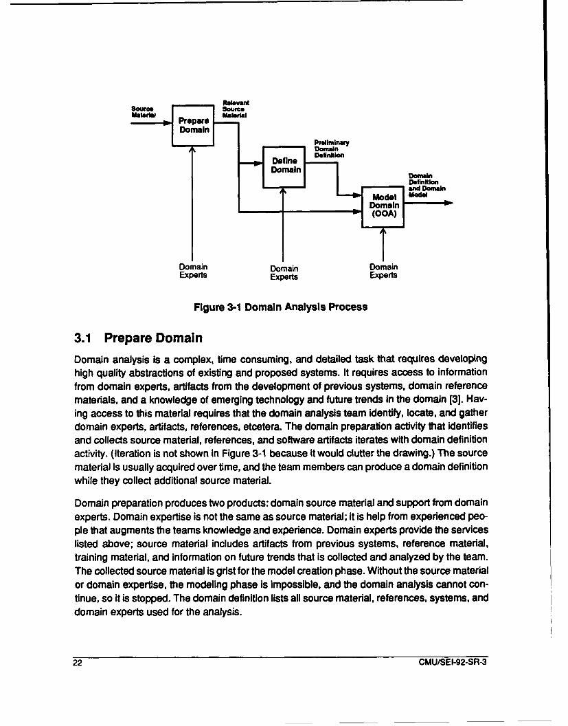
In this chapter, we give an overview of the domain analysis process; in the following chapters,we describe the domain analysis process and products in detail. Figure 3-1 identifies three do-main analysis phases. These three phases: prepare domain, define domain, and model do-main, are described in this chapter. We also explain the relationship of the phases and theiroutputs. The majority of the analysis is done in model domain; prepare and define domain arepreliminary phases where sources are collected and the problem is bounded. Domain expertsare required to support each of the three phases.
Domain experts provide several important capabilities; they:
" identify source material. Domain experts are the best source for identifyingsoftware artifacts from existing systems and reference material. Frequently,the domain experts have taught classes or given presentations that describethe domain. From this material, they can identify references and provide ahigh-level view of the domain.
"* answer questions. During the analysis process, there are issues that cannotbe resolved without assistance from someone who is experienced in thedomain. Questions can be submitted to the domain experts. The answers tothese questions keep the analysis moving and heading in the right direction.
"* identify future trends. Domain expertise includes a broad knowledge in thedomain. The domain analysis team does not usually have access toinformation on future trends. Without this information, the results of domainanalysis will not remain viable long enough to recover the cost. Thisinformation is also necessary for defining scenarios during the modelcreation phase.
" review results. The validation of domain analysis results is difficult. Domainexperts can help to validate the results by reviewing the domain definitionand model. The domain experts also can evaluate the level of detail todetermine if the results will be used. If the results are too detailed and anabstract view is not produced, then the results may not be used. Having acomplete package that aids the reuser in understanding the domain is allimportant.
CMU/SEI-92-SR-3 21
Relevant
Domain Dmi
3.1 Preare o ari om xIai
DeleDefin ito
domain edomain Definitionmcolyaind f tD in te DomainModel Ma"le
-I(OOA)
TDomain Domain DomainExperts Experts Experts
Figure 3-1 Doman Analysils Process
3.1 Prepare Domain
Domain analysis is a complex, time consuming, and detailed task that requires developinghigh quality abstractions of existing and proposed systems. It requires access to informationfrom domain experts, artifacts from the development of previous systems, domain referencematerials, and a knowledge of emerging technology and future trends in the domain [3]. Hav-ing access to this material requires that the domain analysis team identify, locate, and gatherdomain experts, artifacts, references, etcetera. The domain preparation activity that identifiesand collects source material, references, and software artifacts iterates with domain definitionactivity. (Iteration is not shown in Figure 3-1 because it would clutter the drawing.) The sourcematerial is usually acquired over time, and the team members can produce a domain definitionwhile they collect additional source material.
Domain preparation produces two products: domain source material and support from domainexperts. Domain expertise is not the same as source material; it is help from expnrienced peo-ple that augments the teams knowledge and experience. Domain experts provide the serviceslisted above; source material includes artifacts from previous systems, reference material,training material, and information on future trends that is collected and analyzed by the team.The collected source material is grist for the model creation phase. Without the source materialor domain expertise, the modeling phase is impossible, and the domain analysis cannot con-tinue, so it is stopped. The domain definition lists all source material, references, systems, and
domain experts used for the analysis.
22 CMU/SEI-92-SR-3
3.2 Define Domain
The domain definition is delivered and maintained in the Active Repository (See Figure 2-2).This top-level view of the domain uses the same notation as the domain analysis. The defini-tion bounds the domain and is used by the analysts to clarify what is and what is not availablefor reuse. Potential users can quickly determine if their needs can be met by the results of thedomain analysis. The domain definition includes:
"* top-level subject diagram
"* top-level whole-part diagrams
"* top-level generalization-specialization diagram
"* domain services
"* domain dependencies,
"* domain glossary, and
"* textual description.Finally, the domain definition identifies the context for potential reusers. For example, if we hada math library for real numbers, and a developer had hardware with only integer operations,then he would require an integer square root routine. His searching could be limited to the do-main definition, if the definition was based on data types or objects. The developer's use of thedomain definition could be productive, if he identified and adapted the real square root routinefor his use. The notation chosen to represent the domain definition is the same notation cho-sen to represent the domain model. The domain definition identifies top-level objects and de-fines visible services in the domain. So, the JODA domain definition would describe all theobjects as real number objects in the above example, but it would also describe the squareroot service. Although the techniques used to produce a domain definition are the same tech-niques used for domain analysis, the definition activity has been separated from analysis andincluded in preparation because of timing and the importance of restricting the scope of thedomain. The process of domain definition is described in Chapter4.2.
3.3 Model Domain (OOA)The JIAWG model creation phase is an extension of the CYOOA method. This phase containsthree activities: examine object life-histories and state-event response, identify and walk-through scenarios, and abstract and group objects. These activities are iterated since all rele-vant information cannot be identified in one pass. These activities are neither discrete nor dothey occur sequentially. The domain analysis team moves freely between activities, but thescenario and abstraction activities are more effective when a basic model has been identified.In fact, it is difficult to abstract and group objects without having already identified and definedthe objects.
The first activity, examine object life-histories and state-event response, is derived fromCYOOA and has not been changed. C''OOA has defined five subactivities: identify objects,
CMU/SEI-92-SR-3 23

define structure, identify subjects, define attributes, and define services. The analysts mayperform these activities in any order, but the goal is to identify, define, and relate objects.These CYOOA activities are like scenarios but restricted to single objects; more global sce-narios are used to validate and refine the domain model.
The second activity identifies, defines, and simulates domain scenarios. Experts use this basicactivity to define and implement software [1]. These scenarios identify a series of services thatare executed by the objects to provide high-level services to users and other systems. For ex-ample, a basic capability of a stores management system is to help the pilot release a bomb.The release process has several requirements that must be met before stores managementwill drop the bomb. The aircraft must be in air-to-ground mode, master arm must be selected,and a bomb and a delivery program must be selected. Once these conditions are met, thepickle button on the stick will release a bomb. Within each domain, there are many services,but to the external world there are only a few scenarios for each domain.
The final activity abstracts and groups objects so that the model is widely applicable and sothat the reuser is introduced to the domain gradually. The objects in the domain can begrouped in two ways: first, by subject, and second, by whole-part structure. Whole-part struc-ture is the decomposition technique of CYOOA, and the emphasis and discussion in CYOOAare adequate. The description of subjects in CYOOA is adequate to understand them, but theemphasis in identifying subjects is inadequate. In any domain, there are several detailed con-cepts the user must grasp. A high-level view of these concepts is necessary so that the reuseris not lost in the detail. Figure A-5 is such a description for OBE systems; it identifies the mainelevator concepts and their relationships. Abstract descriptions of the domain are necessaryto maintain the interest of the analysts, reviewers, and the reusers. Abstract views help thedomain analysts to clarify their understanding. This activity depends on the existence of a ba-sic domain model.
This model creation phase refines the domain definition and produces the domain model, thatis stored in the active repository, consists of both diagrams, Figure A-1 1, and class specifica-tions, Appendix B.3. This phase also adds terms to the domain glossary. Domain terminologymust be defined so that the analysis team, the experts, and the eventual users will understandthe information. Terminology is captured in the domain definition document and maintained inthe Active Repository. In the next chapter, we describe the products that go into the Active Re-pository.
24 CMU/SEI-92-SR-3
4 Domain Analysis Products
In this chapter, we describe the two domain analysis products: the domain model and the do-main definition. The domain definition represents information that is similar to the model, butthe definition serves a different purpose. The domain model is a complete view; it contains thecodified knowledge that is extracted from domain experts, existing systems, and future trends,and it represents the analyst's understanding of the domain. The domain definition is a top-level view of the domain; it defines the attributes and services of visible objects, the highestlevel whole-part structure, a high-level gen-spec structure, and a top-level subject diagram.The domain glossary is a list of terms that are necessary to understand the other products,and it is included in the domain definition. We also briefly describe DoD standard require-ments, the specification produced by the reuser during software requirements analysis. TheDoD standard requirements are a separate view of the domain, but the information has beentransformed so that it can be included in a Software Requirements Specification (SRS). DoDstandard requirements are specifications that do not contain the variation defined in the do-main model, but have been instantiated so that the variation is removed. DoD standard re-quirements specify a single system in the domain.
We believe that understanding the products associated with the process will provide the read-er with focus. Each of the products consists of diagrams and specifications, most of which aredefined in Object-Oriented Analysis [7]. Ideally, the problem space description is concise, easyto understand, and abstract, but this isn't the case for most domains. A complex detailed de-scription is more common. Domain analysis is a labor intensive, complex process which mustcommunicate a large amount of detailed information to a knowledgeable reuser. The domainmodel is the key product and will be described first, while the domain definition which is simplya high-level view of the domain will be described last. (This is not the order in which the prod-ucts are produced, but the domain model is central to domain analysis. Therefore, it will bediscussed first.) For the domain model and domain definition, we describe:
9 the requirements that must be satisfied, and
e the notation used to define the product.
4.1 Domain Model
The domain model is used to collect, organize, and represent all domain information. The in-formation is collected using diagrams and specifications defined by CYOOA. Several types ofdiagrams are included in the domain model, such as gen-spec diagrams, whole-part diagrams,state-event diagrams, scenario diagrams, etcetera. After the initial analysis, the domain modelcan be modified to update the domain analysis results. Its primary use, however, is to providea framework in which to collect and organize information. Before we describe the domain mod-el in detail, we list the requirements that it must support.
CMU/SEI-92-SR-3 25

4.1.1 Requirements for the Domain ModelThe purpose of the domain model is to represent the problem space. It defines all the domaincapabilities and their variations and combinations. To help the user understand the domain,the model presents an abstract view that identifies the significant relationships and services.To help the user apply the capabilities, the domain model must describe how the capabilitiesare related through scenarios, and the rationale for how and when to use each capability.Since we want the capabilities to be widely applicable, they should also be abstract. Therefore,the domain model must describe:
1. the domain's major parts,
2. the objects and abstractions (classes),
3. the relationships between these objects or abstractions (classes),
4. the attributes and constraints on the abstractions (classes),
5. the services that are provided by these abstractions (classes),
6. scenarios that define the more dynamic aspects of the domain, and
7. the rationale for choosing an instance, option, or variation over another (rules ofthumb). Rationale includes the: risks, trade-offs quality issues (performance,portability understandability, etcetera), and scenarios of use.
The domain model requirements are listed above, but some quality factors are important andneed to be acknowledged. These qualities are necessary if the domain model is to be effectiveand remain viable over changes in technology, time, needs, people, and budget. To supportthese changes the domain model must be:
* adaptable* understandable
* usable,
* correct, and* maintainable.
To meet the requirements listed above for the domain model, we must analyze, organize, andrepresent a large amount of information. The organization of this information is done graphi-cally, but the object specifications are textual. Below, a description is given for each domainmodel diagram, and we identify the requirements that the diagram supports. These descrip-tions are listed in order of importance. The class is the basic element of CYOOA and the do-main model; the structure and subject diagrams define the domain structure; and, the scenariodiagrams describe the dynamic aspects of the domain. The domain model includes:
* class specification. Class diagrams define the class, their attributes andservices [7]. Class diagrams make a contribution to solving domain modelrequirements 4, 5, and 7.
26 CMU/SEI-92-SR-3
"* structure diagrams. Structure diagrams identify the commonalities,abstractions, and variations of the domain classes, and they identifycomplexity in the domain [7]. Structure diagrams contribute to meetingdomain model requirements 1, 2, and 3.
"* subject diagrams. Subject diagrams identify the amount of information that ispresented to the user at one time. The grouping of objects is a kind ofabstraction, and subject diagrams also identify interfaces between thesegroupings. They address requirements 1 and 2 for the domain model.
"• scenario diagrams. Scenario diagrams identify the high-level services thatthe domain provides, and they bind the domain services into comprehensivegroups. Scenario diagrams define the domain event response and life historyinformation similar to object life histories of Coad and Yourdon [7]. Scenariodiagrams address requirement 6 for the domain model.
4.1.2 Class SpecificationsClass specifications are a major element of the domain model. They don't define the domainstructure, but they do define the details. Class specifications are more textual than graphic.They are template driven and a formal language, as recommended by Coad and Yourdon [7].These class specifications list and define their attributes, connections, constraints, rationale,and services. As the user we-ks within the domain, the services become more familiar, andthe need to refer to them a3creases. Also, the names of the attributes and services may besufficiently mnemonki; _., that they can be understood without detailed specifications. In Ap-pendix B.1 1, for e.ample, the service ring for the Elevator Arrival Bell does not need to be de-fined. In Appendix B, examples of class specification are given; full descriptions are given inChapter 3 of Object-Oriented Analysis [7]. Class specification parts are described below in or-der of importance. Attributes and services define the class; the state diagrams provide moredetailed information on that definition.
4.1.2.1 Class AttrIbutesThe attributes of a class define the data which is used to describe an instance of a class. Fre-quently, this data needs to be retained over time. In this sense, class attributes are very similarto class variables from Smalltalk. (Smalltalk is a trademark of Xerox.) In the specification, weidentify the attribute and its type, define its range constraints, identify any rationale, and a tex-tual description. For attributes that are used in an external interface, we must identify the vis-ible service (source capability) and its nane (project unique identified), and name the attributewith a project unique identifier. For the attributes that are used in an internal interface, we mustidentify the domain service and its name (project unique identifier). We must also identify thevisible service that it supports. For example, #_elevators in Appendix B.2 is an attribute thatdefines the state of the class of type integer of range 1 to max_#_of elevators; it is the numberof elevators that is accessible from the lobby.
4.1.2.2 Class ServicesThe services of a class define the processing performed on or by the class when requested ortriggered. These services can be requested by other classes or caused by events or users of
CMU/SEI-92-SR-3 27
the service. For example, in Appendix B.2, the requestelevator-up service comes from theRequest Elevator Up Button. If the button is not already on, the request is sent to the Control-ler. The lack of a service description implies that this is a simple service for which a detaileddescription is not required.
4.1.2.3 State DiagramsState diagrams are useful for defining system behavior, event-response, concurrency, and theorder of processing. These diagrams are not required by Coad and Yourdon, but they may beused for more complex systems to describe system behavior (system dynamics). State dia-grams, as defined in Statemate [15], are effective for specifying real-time performance require-ments.
4.1.3 Structure DiagramsGen-spec and whole-part diagrams describe the complexity in the problem space. These dia-grams define what is common and what is different in terms of classes and structure. Whole-part diagrams define the composition of the domain while the gen-spec diagrams identify thevariation in classes; these diagrams define the structure of the domain.
Another feature of the gen-spec diagram is to indicate that a relationship for specific instancesdoes not exist. For example, in Figure A-10, the Top Floor Elevator Lobby does not have arelationship with the Elevator Up Arrival Light. This light means that an elevator is at this floorgoing up. One can not go up from the top floor, so this connection is not present. This is indi-cated by an "X" at the beginning and end of the relation line. The implication of the informationin Figure A-1 0 is that the Top Floor Elevator Lobby does not have an Elevator Up Arrival Lightand Up Request Button and does not provide a reqelev up service, and the Bottom Floor El-evator Lobby does not have a Down Elevator Arrival Light, and a Down Request Button anddoes not provide a reqelevdown service.
4.1.4 Subject DiagramsSubject diagrams provide a means for controlling how much of the domain model the readerconsiders at one time. The highest level subject diagram is included in the domain definition.Other lower level views are also possible (see Figure A-5). In a large domain, subject dia-grams that group the major elements of the domain are a necessary and an effective mecha-nism for controlling how much of the domain the user must comprehend at one time. If thereuser or the domain experts cannot examine the domain a piece at a time, they may concludethat it is too complex and not worth their time. Using subject diagrams to present a simplifiedview of the domain will help reusers and reviewers to understand the domain model. In theOBE systems example, two levels of subject diagrams have been defined. At the highest level,Office Building Elevator Systems provide services to Users. The more detailed subject dia-gram (see Figure A-5) has seven objects (Users, Service Button, Status Indicators, Elevators,Elevator Lobbies, Doors, and Controllers). The Users interface only with the Service Buttonsand Status Indicators, while the Controller and the Doors interface with Elevators and Eleva-tors Lobbies. The Elevator Lobbies and the Elevators also interface with the Service Buttons
28 CMU/SEI-92-SR-3
and Status Indicators. A simplified view is essential for users to understand the domain. Theamount of detail in even small domain is so large that one must have a simplified view to getstarted. This simplified view of the domain should contain seven plus or minus two subjects;this simplicity makes it easier to understand the details.
4.1.5 Scenario DiagramsScenario diagrams capture the dynamic aspects of the system. Two possible notations forscenario diagrams are R-nets as used in SREM [2] and statecharts [15]. The notation pro-posed by Coad and Yourdon does not have a mechanism for defining performance require-ments across classes or for showing concurrency if it is required. Statecharts have the abilityto specify these requirements and are used to define scenarios in JODA [15]. Domain servicesare used by applications engineers to support larger requirements; stores management sup-ports bomb targeting and release. These combinations of services need to be documented forthe applications engineer who uses the domain analysis results. StateCharts are being usedto define these systems. Scenarios also help reduce the amount of complexity the reuser ordomain expert must comprehend, and they also define the context for domain objects andservices.
4.1.6 Evolution of the Domain ModelDuring the development of new systems from RSOs, there are requirements that are not cov-ered by the domain model. These requirements must be included in the domain model, andthe appropriate reusable artifacts modified. Changes that result from applications engineeringfall into the same classes that are described above. Class attributes or services may be addedor modified, or changes may be made to the whole-part structure. We may also add new ob-jects to the domain model causing the biggest change to the domain model. For example, ifthe system being engineered has new requirements, these must be included in the domainmodel along with the appropriate update to the domain definition. The design and implemen-tation phases of domain engineering must also be revisited to modify the RSOs that supportnew requirements. This evolution takes the domain model full circle. The domain model is cre-ated during domain engineering, used during applications engineering, and updated again onthe basis of the changes that are identified during applications engineering.
4.2 Domain Definition
The purpose of the domain definition is to help the user determine if these domain analysisresults will be useful in the new system that he is developing. The domain definition is a top-level view of the domain, and it describes the context in which the domain is useful. The do-main definition answers two questions:
"* Does this domain provide capabilities that I need in the new system?
"* Can this domain be adapted to work in the context of the new system?
CMU/SEI-92-SR-3 29
Consider again, the need for an integer square root function when we only have real numbermath routines. The domain definition for a math subroutine library (absolute value, floor, ceil-ing, square root, trigonometric functions, and logarithmic functions) should describe the follow-ing for the user: the data type, the function, the constraints on using the routine, anddependencies such as the computational method and the precision of the machine. The de-scription of the data type would tell us that we don't have any integer functions, but we do havea real square root function that might be adapted. The data type, function, and constraints an-swer the first question; the dependencies, data type, and constraints answer the second ques-tion.
4.2.1 Requirements for the Domain DefinitionThe domain definition is used to determine whether or not the new system is within or related
to the domain. The domain definition identifies the relationship of new problems to the resultsof domain analysis. To answer the two questions identified above, the domain definition de-fines:
1. the domain interfaces,
2. the services the domain provides through its interfaces,
3. the domain boundaries (i.e., what domains are very similar, but what attributes andservices determine inclusion and exclusion),
4. the source material, references, and domain experts consulted to produce thedomain model,
5. the major elements or subdomains of the domain,
6. the terminology used to define the domain, and
7. the domain dependencies (i.e., the services provided to the domain through itsinterfaces)
The terms that are defined during domain analysis are necessary for the user to understandthe domain concepts, the domain definition, and the domain model. Many organizations defineand use local terms (that have evolved over many years) for concepts, abstractions, services,and constraints. These definitions are not equivalent from one organization to another. Thedomain terminology should define the relevant terms, concepts, constraints, equations, andconstants.
The domain definition requirements listed above have been identified from the planned use ofthe domain definition. From these requirements, we have identified a set of diagrams that meetthose needs. Context description is another term which is frequently used to describe the set-ting in which a domain will function. The use of context description has been derived from thetop or zero level data flow diagram of structured analysis. This diagram identifies the externalinterfaces which define the system context. Domain definition is preferred over context de-scription and will be used in this document because the user needs to know more than just the
30 CMU/SEI-92-SR-3

context. The user needs to know what is defined as in the domain. The domain definition in-cludes:
" Top-Level Subject Diagram. The Top-level subject diagram identifies theother systems or subsystems with which the domain interfaces. This diagramhelps meet requirement 1 above.
" Top-Level Whole-Part Diagrams. These diagrams define the whole of whichthe domain is a part, and the parts when the domain is the whole. Thesediagrams help to meet requirements 1, 2 and 5.
"* Top-Level Gen-Spec Diagram. This diagram identifies the attributes andservices that distinguish this domain from similar domains. This diagramhelps to meet requirements 2 and 3. -
" Domain Services. A list of the services which are visible to external systemsand subsystems. These service definitions satisfy requirement 2.
" Domain Dependencies. A list of the services that must be available fromother systems or subsystems for the domain to meet its requirements. Thesedependencies satisfy requirement 7.
" Domain Glossary. The terms that are used to define domain concepts areessential for the reuser to understand the domain. Terminology evolves overtime and represents an organizational view of the domain. These terms mustbe documented to completely and accurately describe the domain. Theglossary satisfies requirement 6.
" Textual Description. The text binds these lists and diagrams together into aintegrated view. The textual description, that includes: a list of the source andreference materials used by the analysts; a list of software life-cycle objectsfrom systems examined; and a list of domain experts and their areas ofexpertise, should be restricted to a few pages. This description satisfiesrequirement 4, but it also supports all the other requirements listed above.
4.2.2 Top-Level Subject DiagramThe subject diagram identifies the domain interfaces. If the domain is itself a whole system,then this diagram is its external interfaces. On the other hand, if the domain is embedded in alarger system, then these are its interfaces to other subsystems and the external world. Anexample is given in Appendix B.2. The domain in this example is Office-Building Elevator(OBE) Systems. These OBE systems interface with users and moveable equipment. Usersare transported by and receive status from the elevator system, while the equipment is movedby the elevator system. In data flow diagrams (DFD), the highest level (zero level) diagram hasa specific name; it is called a "context diagram." The top-level subject diagram provides thesame information as the DFD's context diagram because it identifies the domain's external in-terfaces; it doesn't identify how other domains are related to the system. Related domains areidentified from the top-level whole-part diagrams.
CMU/SEI-92-SR-3 31

4.2.3 Top-Level Whole-Part DiagramsNormally, there are two whole-part diagrams. The first defines the whole in which the domainis a part; the second defines the parts of the domain.
Figure A-2 defines the relationship of the OBE systems domain to office building transportationsystems domain. An office building has elevators, stairs, and possibly escalators. There mayalso be ramps, or moving sidewalks depending on the precise definition of the higher level do-main. Today, single story office buildings may not be very common, but they are possible.Therefore, the parts (elevators, escalators, and stairs) in Figure A-2 are optional. Also, wemay have more than one elevator system, escalator system, or set of stairs within an officebuilding. Therefore, multiple instances of the parts may make up the whole.
In the context of an office building, it doesn't make sense to have an escalator, stairs, or ele-vators without an office. It also doesn't make sense to have an elevator, escalator, or stairsserve more than one building because these elevators, escalators, and stairs have to be phys-ically located in the building. There is one and only one Office Building Transportation Systemfor each elevator, escalator, or stairs.
Figure A-3 defines the parts of the OBE systems. OBE systems are composed of a set of el-evators, a controller, and elevator lobbies. The connections in Figure A-3 define the range ofthe whole-part relationships. An elevator system is composed of at least one elevator and twoelevator lobbies. A controller is optional because a system with one elevator and two lobbiesdoesn't require a controller to provide fair and equitable service.
An elevator, controller, and an elevator lobby are the parts of the elevator system. An elevatoror a controller may not be part of more than one elevator system, but an elevator lobby maybe part of more than one system when the elevators are grouped to serve a subset of the floorsin a skyscraper. These relationships are defined in Figure A-3.
After the whole-part diagrams have been examined, we can see that defining the context forour domain is helpful. We are not looking at elevators in malls, shopping center, factories, air-ports, or warehouses. We are examining elevators in the context where people are the primaryusers. Elevators in factories and warehouses move equipment or inventory. Elevators in malls,shopping centers and airports primarily move people, but the traffic flow is regular, and thepeople are frequently carrying something. By examining the whole-part structure of the eleva-tor, we can see that these OBE systems have not included escalators in the domain. Someoffice buildings may have shopping facilitie ; ý'le lower floor and use escalators for transpor-tation between those floors. These escalatois are not part of the OBE domain. Therefore, theelevator system tor a building with shops on the first two or three floors that are serviced byescalators is related to but not included in the OBE domain because it has escalators, whichare not in the domain. We might consider the combined elevator escalator systems as a build-ing transportation system, but it would be a different domain.
32 CMU/SEI-92-SR-3
4.2.4 Top-Level Generalization-Specialization DiagramWithin the domain definition, the classification (in CYOOA, generalization- specialization dia-grams are also called classification diagrams) diagram identifies the commonality and variabil-ity at the top level of the domain. Classification structure also helps to define the domainboundaries. The classification structure does not accomplish this alone, but in cooperationwith the other diagrams in the domain definition. Figure A-4 defines a classification structureon Elevator Systems. The common attributes and services are given in root class ElevatorSystem.
In this classification structure, four attributes of building elevator systems have been identified.They are: #_elevators, #_elevatorlobbies, capacity, and destinationset. Two services havealso been identified: travel up and traveldown. Each elevator system in the class shares theattributes and services defined in the root of the gen-spec structure unless the attributes orservices are excluded by an 'x." In this case, no attributes and services are excluded, but spe-cific values are given which define the instances of the class. In Figure A-4, for example, in thePenthouse Elevator System, there are only two lobbies and one elevator. Also, the servicesare restricted from travel-up and traveldown to gopenthouse and go-lobby. The Freight El-evator System has two additional attributes: padding ar,," manual control. These attributes dis-tinguish the freight systems from the more general Building Elevator System. Anotherdifference is the hold service for the Freight Elevator System. Further extension of this gen-spec structure is possible, but it does not serve the purpose of this document to fully detail thatstructure. This domain analysis is concerned with OBE systems; each of the classes in FigureA-4 that is not included in the domain is marked with an Yx" preceding the class name. Thisnotation further clarifies the domain definition.
The common services provided by the domain's classes are important for defining the bound-ary. If the utility of the domain is being evaluated, then the user needs to determine whetheror not the services from the domain's classes meet the requirements of the new application. Ifthey do not, then updating the domain model is one possibility. Another possibility is using onlythose portions that apply. A very important benefit of the gen-spec and whole-part structure isthe ability to identify the applicability of partial solutions, since some new systems will lie out-side the original domain boundary. The full specification of the visible domain services is in-cluded the domain model.
4.2.5 Domain ServicesIn the domain definition, the domain services are used to determine whether or not a newsystem's requirements can be adequately supported by the results of a previous domainanalysis. This means that the services provided at the domain interface must meet therequirements of the new problem statement. In the OBE systems in Figure A-i, the highestlevel interface is between the user and the Elevator Lobby and Elevator classes. This dualinterface implies that some subset of the services provided by those classes defines thedomain services. From an examination of Figure A-12, the services available from the ElevatorLobby are: reqelev.up, reqelev down, open-doors, and closedoors. Also, from an
CMU/SEI-92-SR.3 33
examination of Figure A-1 1, the potential services from the Elevator are: status, sound_alarm,
closedoors, openridoors, selectdest, signal-arrival, unlockreardoor, lock reardoor, and
stop. After examining these lists based on the subject diagram in Figure A-i, the elevator user
has access to the following services:
"* req.elev.up from Elevator Lobby,
"* reqelev down from Elevator Lobby,
"* soundalarm from the Elevator,
"* opendoors from the Elevator,
"* closedoors from the Elevator,
"* unlockreardoor from the Elevator,
* lockreardoor from the Elevator,
* stop from the Elevator, and
* selectdest from the Elevator.
These services are the same services defined by the Service Button class defined in FigureA-9. One way to present the services in the domain definition, is to define a subject diagramthat includes all the classes which provide a domain service. Another effective means for iden-tifying visible services is from the scenarios defined for the model. In the OBE example, we
have an abstraction, Service Button, which achieves the same effect.
4.2.6 Domain Dependencies
It is not sufficient to document only the boundary of the domain. Basically, all domains dependon:
"* the availability of services from external objects,
"* the correct performance of services in the domain's parts,
"* the maintenance of the system,
"* the availability of runtime resource, and
"• the development environment support that is needed to use the domainanalysis results to construct a new system (does the compiler support thenecessary options?).
The dependency description helps to define the context for evaluation and application of do-main RSOs. If we consider applying the RSOs derived from a domain analysis to the develop-ment of another system, we must be able to determine whether or not the RSO will functioncorrectly in the system under development. Meeting the domain dependencies is an essentialpart of being able to reuse RSOs; domain dependencies are the requirements which must bemet for the RSOs to function correctly.
For the OBE systems domain, the dependencies are:
o availability of electrical power,
34 CMU/SEI-92-SR-3
"* physical and structural properties of the materials used for construction,
"* structural integrity of the building,
"* maintenance of the system.
In this section, for example, the dependencies of the OBE systems are matched with the gen-
eral classes listed above. Not all dependencies apply. There is no external interface, so there
is no dependency on external services. The subdomains of the OBE systems domain do not
add any dependencies. The OBE systems are also dependent on proper maintenance of the
hardware, motor, cables, and wiring. The availability of power and the integrity of the building
are both part of the runtime environment. The physical and structural properties of the mate-
rials used to construct the system are examples of the development environment.
4.2.7 Domain Glossary
The terminology produced from the review of the source material and references is collected
and provided in the domain definition document. There is no CYOOA notation to capture theterminology, but the terminology should be included as a glossary in any report that docu-ments the model. The domain glossary should be available so that a potential user can under-
stand the domain definition and the domain model. Concepts which are essential to thedomain need to be identified and recorded; any terms which need clarification should also beincluded. In Figure A-1 2, for example, the Elevator Up Arrival Light in the Elevator Lobby indi-
cates that the elevator is located at this floor, and the light is on from arrival through departure.The Elevator Floor Location Light in the Elevator in Figure A-1 1 is on from the time it arrives
at that floor until it arrives at another floor. Thus, Me semantics of the two are different for beingon a floor; these differences need to be identified.
4.2.8 Textual DescriptionThe purpose of the textual description is to bind the diagrams and lists together into one doc-ument; the goal of this definition is to help potential users determine whether or not their re-quirements can be satisfied by the RSOs of the domain. The description also lists:
"* the source material (existing systems documentation) that was used for theanalysis,
"* the sources for, and descriptions of, future trends in the domain,
"* the domain experts, reviewers, and reviews of the domain material, and
"* the domain mission, i.e., the operational context that it supports.
The textual description provides an integrated view of the domain and helps the reader tomake the transition from one diagram to the next. Another benefit of the domain definition doc-
ument is that it can easily be disseminated, reviewed, and updated. It is essential that the do-
main definition be kept current through continual review and update.
CMU/SEI-92-SR-3 35
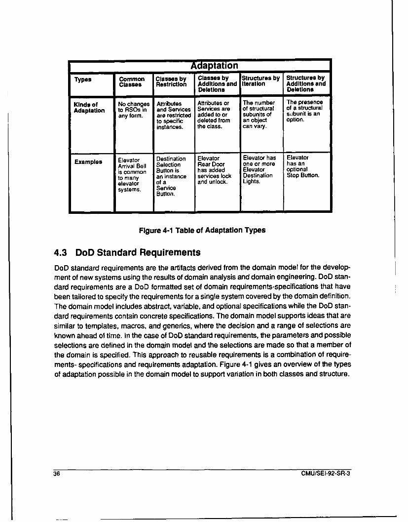
TAdaptation
Types Common Classes by Structures by Structures byClasses Restriction Add itions and Iteration Additions and
Deletions Deletions
Kinds of No changes Attributes Attributes or The number The presence
Adaptation to RSOs in and Services Services are of structural of a structuralany form. are restricted added to or subunits of subunit is an
to specific deleted from an object option.instances. the class, can vary.
Examples Elevator Destination Elevator Elevator has Elevator
Arrival Bell Selection Rear Door one or more has an
is common Button is has added Elevator optional
to many an instance services lock Destination Stop Button.
elevator of a and unlock. Lights.systems. Service
Button.
Figure 4-1 Table of Adaptation Types
4.3 DoD Standard Requirements
DoD standard requirements are the artifacts derived from the domain model for the develop-ment of new systems using the results of domain analysis and domain engineering. DoD stan-
dard requirements are a DoD formatted set of domain requirements-specifications that have
been tailored to specify the requirements for a single system covered by the domain definition.
The domain model includes abstract, variable, and optional specifications while the DoD stan-
dard requirements contain concrete specifications. The domain model supports ideas that are
similar to templates, macros, and generics, where the decision and a range of selections are
known ahead of time. In the case of DoD standard requirements, the parameters and possible
selections are defined in the domain model and the selections are made so that a member of
the domain is specified. This approach to reusable requirements is a combination of require-
ments- specifications and requirements adaptation. Figure 4-1 gives an overview of the types
of adaptation possible in the domain model to support variation in both classes and structure.
36 CMU/SEI-92-SR-3

5 Prepare Domain
In this and the following two chapters, we describe the domain analysis phases in detail. Foreach phase, the purpose of the phase, the inputs to the phase, the outputs from the phase,and the review at the end of the phase are defined. In some cases, the phase's input or outputmay be more than data. For example, the output from a step can be to obtain support from adomain expert to review and comment on the domain analysis results. Figure 3-1 provides anoverview of the entire domain analysis process while Figure 5-1 identifies the two domainanalysis preparation activities: acquiring domain expertise for the analysis and collectingsource and reference material.
The results of the preparation phase are reviewed at the end of the definition phase to ensuretheir accuracy, reality, and viability for reuse. The domain definition phase is iterated with thepreparation phase because obtaining information, interacting with domain experts, and re-viewing the definition are essential to providing a precise definition. Since it takes time to iden-tify and acquire the required sources, the analysts will not be fully occupied during theidentification of domain expertise and source information and can begin the analysis by defin-ing the domain. The domain definition controls the scope of the analysis effort, and may bechanged during the domain modeling phase, but an early definition is necessary to focus theteam's activity. Before defining the domain, sources for domain analysis are identified, locat-ed, and collected.
Availablesource Acquire DomainMaterial Domain Expalser
F~~gure 5-1 Domain PepraioPocs
E iexpertisefor the thAnalysis
RelevantCollect Source
Source Materialand
ReferenceMaterial
Figure 5-1 Domain Preparation Process
Figure 5-1 identifies the activities for gathering domain source material. The purpose of these
activities is to identify, locate, and obtain the domain expertise, reference material, and system
artifacts for the domain modeling. This activity is executed in parallel with domain definition,
and the review at the end of the domain definition activity examines the material collected and
expert support obtained in order to determine if the support is adequate.
The inputs to domain preparation are the available source material. The organization's busi-ness plan helps to identify domain experts who recommend domain reference material and
CMU/SEI-92-SR-3 37

docume•tation on existing systems. These experts are the best source for identifying futuretrends in tjie domain because they have knowledge of, and experience with, several systems.Domain experts also identify future trends that are necessary to keep the results from becom-ing obsolete.
The outputs from the preparation activity are the sources and the material for available domainexpertise and relevant source material.
JODA recommends reviewing domain documentation from three existing systems becausethe domain analysis should cover as much of the domain as possible. Analyzing three previ-ous systems will not guarantee that coverage, but only examining one system may not provideenough coverage. Examining two systems is better than one, but three provides even morebreadth. Examining more than three existing systems could be productive, but the analysismay not be cost effective. We rely on the experts to identify areas that are overlooked. We useanalysis (reverse engineering) to identify detailed information and confirm expert views.
5.1 Acquire Domain Expertise for the AnalysisJODA requires the availability of domain expertise. Three potential sources for identifying do-main experts are:
0 upper-middle managers,
9 chief architects from previous developments, and9 chief architects from current developments.
To obtain this expertise, senior management must support the need to make a domain ex-pert's time available. When the experts are identified, they are informed of the notation thatwill be used so that they may become familiar with the CYOOA notation. Support from domainexperts must also be obtained because the results will be detailed and require a concentratedeffort from the domain expert to perform the required review. Also, the domain analysis teammust concentrate on producing results that can be quickly and easily understood. If domainexpertise cannot be obtained through this or alternative means, the domain analysis shouldnot continue because the results can not be adequately validated.
5.2 Collect Source and Reference MaterialDomain experts can identify and recommend applicable sets of system documentation anddomain reference material for the analysis team. After a list of pertinent reference material anddomain documentation has been compiled, the materials are evaluated. The quality and cov-erage of the system artifacts are the factors that should be used to select information for do-main analysis. An optimal set of documentation would include broad, high quality coverage. Inreality, both quality and coverage may be lacking. Obtaining these materials will be aided bythe support of senior level management. With senior level management support and guidancefrom the domain experts, the analysis team gathers the necessary reference material and sys-tem artifacts.
38 CMU/SEI-92-SR-3

Obtaining access to classified or proprietary material can be a problem, so unclassified andnonproprietary sources and references are preferred. The classification of a domain is a realhindrance to open discussion and review. Regardless of the classification and sensitivity of thematerial, the appropriate source material and reference must be obtained for the domain anal-ysis to be successful.
Another potential source of information is from previous domain analyses. These efforts maynot have been called "Domain Analysis", but they may contain essentially the same "Generic"or "High Level" information. Domain experts should be queried as to whether or not they areaware of previous studies that have attempted to capture, analyze, or represent informationabout the domain. These previous studies can provide an excellent starting point for furtheranalysis.
The domain preparation activity occurs in parallel with domain definition, and the decisionwhether or not to proceed with domain modeling is made at the review. If the resources for thedomain analysis are determined to be insufficient by the domain experts, then the proposedanalysis must be re-examined with the sponsoring agent.
CMU/SEI-92-SR-3 39
40 CMUISEI-92-SR-3

6 Define Domain
In this chapter we describe the domain definition activity. Figure 6-1 gives an overview of thedomain definition phase. The definition is used by potential users of the domain analysis re-sults to determine if their requirements can be met by the results of a particular domain anal-ysis.
The source and reference materials obtained during the preparation activity are analyzed tocreate a domain definition that is refined during domain modeling. The better the definition inthe early phases, the easier the successive phases will be. From the domain selection processand from discussions with the domain experts, the team will have started to form a domain def-inition, but it is necessary for that definition to be documented, reviewed, analyzed, and updat-ed.
The output of this activity is a domain definition which is described in detail in Section 4.2above. The preliminary domain definition will not contain all the detail and precision that willbe present in the final version, but the following outputs are produced:
"* top-level subject diagrams,
"" set of whole-part diagrams,
"" domain services,
"" domain glossary,
"* domain dependencies, and
"* textual description.
6.1 Define Domain Context
Initially, the domain context needs to be defined. It is easier to retrieve that information from adomain expert than to obtain it from system documentation. The domain context may not beeasy to identify from existing systems because the domain may not map directly onto thestructure of previous systems. While interviewing an expert, the domain analyst should ask theexpert to describe the major subsystems or systems with which the domain will interface. Dothese other systems/subsystems provide service to the domain being analyzed, does the do-main being analyzed provide them services, or are both true? The experts should also beasked to characterize that interface: is this a common interface? Is the interface necessary oroptional? What domain requirements can be linked to this interface and service? If the domaindirectly supports a user, then it is useful to review operators' manuals, operations manuals,and service manuals.
To document the context for the domain, JODA requires a high-level subject diagram whichidentifies the customers for the domain services and shows the domain context, i.e., what oth-er systems use its services. This diagram only identifies that there is an interface; it does notidentify the customers for each domain service. The domain customers may be users, other
CMU/SEI-92-SR-3 41

programs, or applications. To validate the subject diagram, the domain analysis team will ex-amine artifacts from current or previous developments. If they extract the information from doc-umentation, then they should review the information with a domain expert. It is important toidentify other systems and subsystems which obtain services and provide services to the do-main. A first cut at this diagram can be made quickly, because as the analysis continues, it willbe refined based on analysis of existing systems.
Relevant.Dfn
Domain WholW-Part Structure,Context Domain Is Part
Systems WholePart Structure,Artifacts Domain Is Whole
DomainExpertse =I lly
-lpStructure Top LevelSublect Diagram
Se tems'Stm
Asfacts S AnalyzeScenarios
DWmwith Domain
EDomaiDoniExpertiseinition
grjDometeson oes6.2 AoayectsysemyArfc
SinterfaceDependencies
Definition d Art.fahis
SDomainDefinition
-- '= l IPreliminary
Review & DomainDomain Upae DefinitionExperts Domainkl-n
Figure 6-1 Domain Definition Process
6.2 Analyze Systems Artifacts
JODA also includes in the definition a whole-part structure where the domain is one part. Thiswhole-part diagram is a variant of the same information presented in the subject diagram
42 CMU/SEI-92-SR-3
above, but when completed, the whole-part diagram identifies services obtained from outsidethe domain. The context for the domain being analyzed need not be fully described, but thewhole-part part diagram does differentiate between peer level subsystems/systems and largersystems or aggregates. Again, this is not a detailed figure; it need not show all services or at-tributes for external objects.
6.3 Identify Domain Structure
JODA also includes in the definition a whole-part diagram where the domain is the whole. Toderive this whole-part structure, a domain expert is interviewed. The information could be ob-tained from system artifacts, but again, it is easier to obtain the domain structure from an ex-pert. In fact, the same expert does not need to provide both whole-part structures. One of theconstant difficulties the team will face is resolving different views of the domain. Therefore, re-solving two different initial views will provide practice.
The analysis team will require access to at least one set of system artifacts and one domainexpert to produce the subject diagram and the whole-part diagrams. Access to more than oneset of documentation is recommended, but since this activity is occurring in parallel with iden-tification of domain source material, one set of documentation may be all that is available. Themost appropriate software artifacts to review are systems and software requirements specifi-cations, high-level software designs, and operations manuals.
6.4 Analyze Scenarios with Top-Level ObjectsTo identify domain services, scenarios are defined that utilize the high-level domain services.To define scenarios, systems artifacts are analyzed and domain experts are interviewed. Sce-narios are very useful for understanding systems [1], and they can be extracted directly fromexisting documentation, like the Tactical Operations Manual for the F/A-18 that describes indetail the procedures the pilot uses to manage his weapons. These procedures corresponddirectly to services of the domain. In this early activity, one must consider the time spent ana-lyzing scenarios, and it must be balanced with preparation effort which is occurring at the sametime. Again, it is easier to obtain scenarios from domain experts than to define scenarios fromsystems artifacts. Identifying services may also be accomplished by examining an object's lifehistory, which is a different kind of scenario.
6.5 Analyze Objects for External DependenciesThe final step in creating the domain definition is to identify domain dependencies by examin-ing each of the requirements listed in Section 4.2.6, Domain Dependencies, and to determinehow each requirement is applied to the domain. After recording the domain dependencies, theanalysis team is ready to document the domain definition for review by the domain experts.
CMU/SEI-92-SR-3 43
6.6 Document Domain DefinitionThe diagrams and services which have been derived by the domain analysis team do not con-vey enough information. The value of such information is enhanced v.'!Ien it is put in contextwith a textual description. The domain definition document is a living document which is -a-viewed throughout the analysis and is delivered with the RSOs and domain model at the con-clusion of domain engineering. Specifically, the document will list and Jefine each domainservice, and each external dependency. The recommended order for these diagrams is:
"* introduction containing references, reviewers, and background,
"* whole-part diagram, where domain is a part,
"* top-level domain classification diagram (not included in initial draft),
"* top-level subject diagram,
"* domain services,
"* whole-part diagram, where domain is a whole,
"• domain dependencies, and
"* domain glossary as an appendix.
JODA also includes a gen-spec diagram in the domain definition, but it is too early in the do-main analysis to accomplish this with any confidence. The gen-spec diagram requires accessto multiple system definitions or extensive discussions with a domain expert to draw out thiscomplex information. A top-level classification structure will always be produced during thecreation of the domain model.
6.7 Review and Update Domain DefinitionThe domain definition process does not terminate until a successful review is held at the endof the phase. Figure 6-2 identifies the activities of the review process whose purpose is to re-fine the domain definition based on the knowledge of the domain experts, and to determine ifthe domain analysis team has the necessary resources to perform the analysis. Reviewing thedomain definition is especially important since the definition controls the scope of domain mod-eling that is about 75 percent of the analysis effort. The domain analysis team reviews the def-inition with the experts, and the analysts describe their analysis approach. This approach mustbe accepted before beginning model creation.
The domain definition document, references material, and documentation of existing systemsare the inputs to the review and update activity. The output from this review is a preliminarydomain definition, used for establishing and maintaining the focus of the domain analysisteam. The reviewers, who have extensive backgrounds in the domain, will be able to add detailand clarity to the definition. They can also identify areas where the documentation and refer-ence materials are weak and suggest additional materials. The intent of the review is to ensurethat the team has identified a coherent domain and obtained resources necessary for analysis.
44 CMU/SEI-92-SR-3

Domain DistributeDefinition Domain
Definition Reviewfor review Package
Review Preliminary DomainDomain Definition
Definitionwith Domain
Experts
Review Domain AnalysisAnalysis GuidanceApproach
Figure 6-2 Domain Definition Review Process
6.7.1 Distribute Domain Definition for ReviewAt least two weeks prior, the domain definition is provided to the reviewers. If the domain ex-perts are not familiar with the CYOOA notation, a meeting may be necessary to teach themthe notation.
6.7.2 Review Domain Defihiution with Domain ExpertsIn this review, the domain definition is reviewed in detail by the domain experts. The feedbackfrom the review is used to refine the domain definition and to identify additional documentation,reference material, and emerging technology.
The whole-part structures that have been defined by the domain analysis team are presentedto the domain experts. These structures need to be examined from a broad perspective to clar-ify and validate the domain context, its major classes, and their relationships. If an omissionfrom the domain's whole-part structure is identified, a decision to add to the whole-part struc-ture may increase the scope of the domain. It is important that decisions that affect the scopeof the domain be made explicitly because what appears to be a small increase in scope cancause a large increase in the domain modeling effort. If structure is added, then the whole-partstructure diagram is updated.
The domain definition should be compared with the more abstract systems artifacts. The do-main analysis team should examine the designs of existing systems to gain an understandingof how the requirements are satisfied, since the issues which generated a particular Implemen-tation may be more apparent in the design than in the requirements. These issues and theirrationale are necessary to understand the domain and document the results. In addition, thereare usually services or features that have not been documented that are necessary to com-plete the domain definition. Only by examining designs and code can these features be iden-tified.
CMU/SEI-92-SR-3 45
The domain definition's subject diagram and services should be reviewed together, since thedomain services define the domain interface. Omissions from the domain services are likelybecause interfaces may have been overlooked. The users of the domain services can be iden-tified by the reviewers. Walking through realistic domain scenarios will clarify issues.
The domain glossary is discussed to identify definitions that are incorrect, and to ensure thatall required terms and concept are defined. If the domain experts can direct the analysis teamto standard references from which they may obtain definition and concepts, this will aid in clar-ifying and documenting the results. Terms and concepts evolve over time within organizationsand will represent the bias of the experts. It is important that these terms and concepts be doc-umented using standard means.
Finally, the domain dependencies are examined from the perspective of what services fromother systems are necessary for the domain to function. If the domain dependencies are in-complete, then the reviewers can help identify additional dependencies. Any external softwaredependencies should be identified, examined, and accepted by the reviewers, because a do-main will not function without these services.
6.7.3 Review Analysis ApproachBefore concluding the review, the analysts will describe their approach to analyzing the do-main. The systems that will be analyzed, the breadth of the domain that will be analyzed, andthe mix of bottom-up and top-down techniques that will be used are presented to the experts.The experts can recommend adding, deleting, or changing the set of systems to be analyzed.The experts should also be queried to determine what they consider proper coverage of thedomain, and how they would approach the analysis proposed by the domain analysis team.Issues that are not resolved are recorded and reported in the review minutes. After the actionitems, guidance, and suggestions recorded during the review have been discussed, the re-viewers should meet without the domain analysis team to determine if they support beginningdomain modeling. The reviewers can identify action items for the domain analysis team tocomplete before they continue. If the reviewers are not satisfied with the approach, the sourcematerial, or the domain definition, then any concerns will be reported in the review minutes anddiscussed with the domain analysis sponsor. It is more cost effective to redirect the analysisearly than to try and fix it later.
46 CMU/SEI-92-SR-3

7 Model Domain (OOA)
In this chapter, the model creation process is described in detail. The process is based onCYOOA and uses the notation of CYOOA to define the domain model. Figure 7-1 gives anoverview of the model creation process. The goal of domain analysis is to define a domainmodel that is derived from an analysis of system artifacts, references, and domain experts sothat it can be used to produce RSOs, especially reusable requirements.
The preliminary domain definition and relevant source material are the inputs to the domainmodeling phase. Information is extracted from the domain experts to define a top-level view ofthe domain, while the reference material and domain artifacts will be analyzed to build up thedetails of the model and increase the team members' understanding of the domain. When adomain expert defines the domain structure, the detailed analysis is faster and easier. The out-put from this step is the domain definition and model that are defined in detail in Chapter 4.
Preimnary I Examine Iclam Speelferlkons
Domai I Iand Whole PattDefinition Object Life- Structure-
Histories andSState-EventResponse I dniyadI=•.s•=
GoWalk-Through aSDomain Instance ConnectionsScenariosII AsrcndSb,,
Sobj=,,Group IG-Stp;:
Objects DmiRe .view and an
I IUpdate Domain_W Domain - ---- 0
Model
Expet
Figure 7-1 Domain Modeling Process
The activities for analyzing the domain are defined in CYOOA [7]. Those activities have beenevaluated and a further refinement and extension is given below. A specific ordering for themodel creation activities is given.
From the domain definition, we get a top-level view of the domain. During the analysis, we willenhance and refine that view by examining the details of the domain. To fully document thedomain, a model is created that defines the whole-part structure from the top of the domain
CMU/SEI-92-SR-3 47
down to the lowest level objects. If the analysis team has difficulty defining the high-level struc-ture, they should analyze some lower level objects to get a better understanding. The analysisiterates from the bottom-up to the top-down through the life-history and the state-event re-sponse of classes. In general, examining complex examples, when such choices exist, willhelp identify more of the structure, the services, and the classes. In the beginning, simple ex-amples should be analyzed to ensure that the domain analysis team understands the JODAmethod and notation. Simple examples are also easier for the team to understand. The simu-lation of scenarios, which is a later activity, refines and expands the class specifications espe-cially the attributes, services, and instance connections. Concurrently with these activities, thedomain analysis team must try to identify generalization and specialization and determinewhat variations exist in the whole-part structure.
7.1 Examine Object Life-Histories and State-Event ResponseThere are two techniques defined in CYOOA for identifying the class services, attributes, andinstance connections. One technique is to examine the life-history of an object to identify thestate changes of each class and identify the services that produce the state changes. Thistechnique does not identify all the error processing and special cases. The second techniqueis to examine the state-event responses of the class. This information is captured in the classspecification using statecharts techniques. For real-time control systems and device driver do-mains, this information is necessary to define the services.
7.2 Identify and Walk-Through Domain Scenarios
After an initial set of classes has been defined using the techniques above, a process that willincrease the precision and completeness of class specifications is to identify and walk throughscenarios. These scenarios are documented using a statechart technique and are an exten-sion to the specifications of Coad and Yourdon. Domain experts should identify and initiallydefine the scenarios that are refined, documented, and simulated by the analysis team. Thesescenarios are documented using statecharts that capture the details. Using the statecharttechniques from Statemate, these scenarios can be simulated and validated. The complete-ness of the analysis will depend on accuracy and realism of the scenarios. To additionally val-idate the scenarios, they should be reviewed with the domain experts.
7.3 Abstract and Group ObjectsFrom the details that are drawn out through the scenarios, the domain analysis team mustraise the level of abstraction. Using the notation of Coad and Yourdon, abstraction is docu-mented with gen-spec structure and subject diagrams. It is through the analysis of the com-mon attributes and services that we identify the generalization-specialization (Gen-Spec)structure that captures the domain variation. For example, an elevator may have Rear Doorsthat require additional Elevator Services Buttons to open and close the Rear Doors. These ad-
48 CMU/SEI-92-SR-3

ditional services are defined in an elevator gen-spec structure. The ability of the notation toaccommodate variation is essential for reuse.
Again, simulating scenarios and case studies with the domain experts are the means to iden-tifying the variations within the domain. The CYOOA process does not focus strongly enoughon producing or identifying abstract classes in the model. JODA requires examining the do-main model to identify abstractions of classes and services. If there are repeating instances ofsimilar problems such as the processing of many message formats, these problems should beanalyzed to identify an abstraction which can be instantiated to cover all cases; an example isthe Doors object defined in Figure A-6. This abstraction was not identified until after the anal-ysis had been completed, but the abstraction for doors provides an abstraction which repre-sents several domain objects. The domain model was updated to include this abstraction inthe domain. The analysis team should attempt to locate and review other domain analyses, toidentify abstractions from other domains that apply to the current domain. If the domain beinganalyzed contains a horizontal domain as defined by McNicholl [21], there may be abstractionsin the horizontal domain which help to identify other abstractions.
JODA requires that the domain model be examined to identify stable interfaces where the spe-cifics vary. For example, device drivers for a Graphics Kernel System (GKS) graphics packag-es have a similar interface, but the implementation can be vastiy different because theydepend on the capabilities of the device. These instabilities are an important aspect of the do-main and require an explicit classification structure to define the different sets of services. Toidentify these stable interfaces with variable implementations, system documentation and ref-erence material are examined for high-level indicators, like hardware, which imply differing ordifferent capabilities.
A similar problem is identifying any instabilities in the domain. For example, if one can currentlyuse different types of sensors (e.g., infrared, laser, or radar) for targeting, and since the class-es, attributes, and services are dependent on the sensor class, then there is some instabilityin the domain. The domain analysis team should attempt to define a virtual interface with helpfrom the domain experts. This virtual interface would map onto the services for each differentmember of the class. If a definition of a virtual interface is not possible, the instability and therationale associated with each variation will be identified to alert potential reusers to the vari-ation. Instability in the domain will not invalidate the domain analysis results since there is val-ue in a partial set of requirements.
7.4 Review and Update Domain Model
Creating and refining the domain model will continue until the reviewers agree that the modelis complete and sufficiently accurate to define the domain. Figure 7-2 gives an overview of thereview process for the domain model. The purpose of reviewing the model is not only to de-termine that the model completely and accurately represents and abstracts the knowledge ob-tained from the documentation, references, and experts, but also to determine that the reviewobtains guidance and support from the domain experts on how to proceed. The termination
CMU/SEI-92-SR-3 49
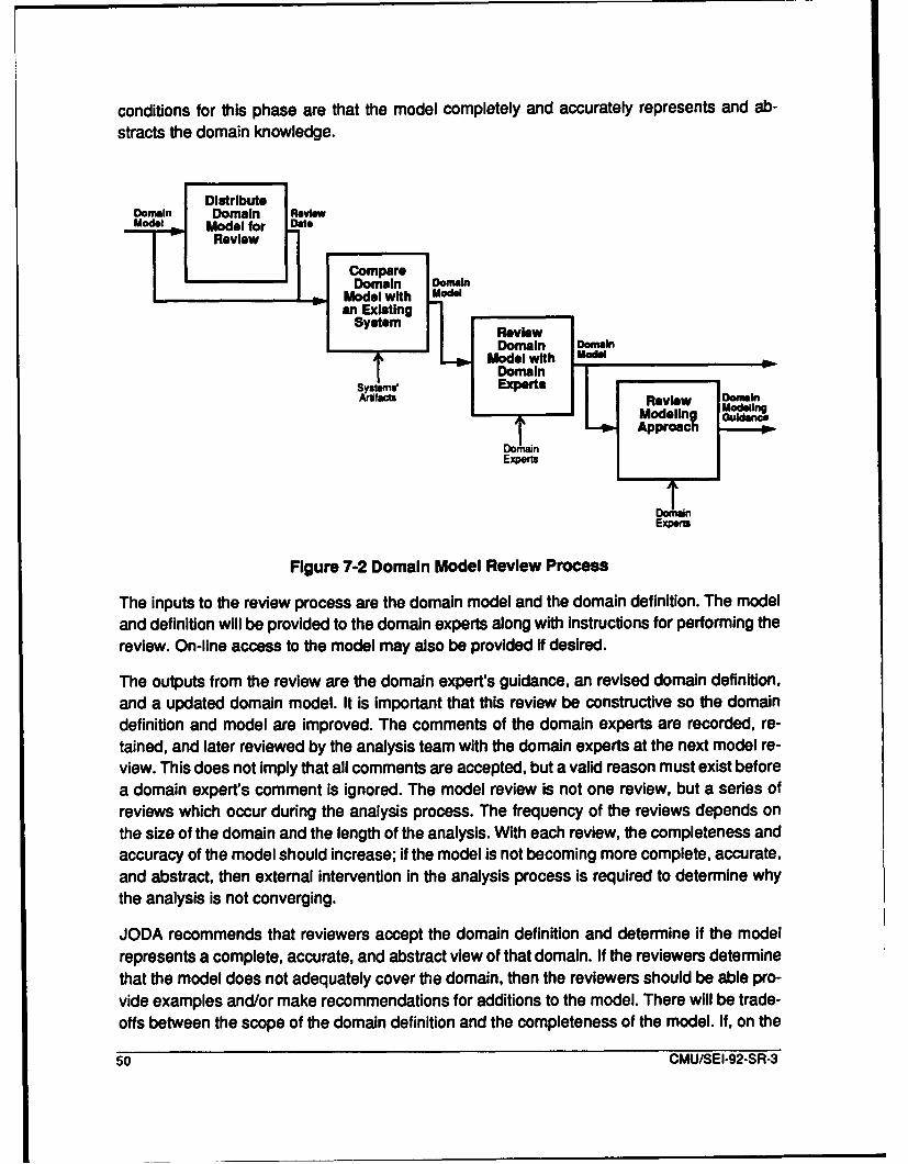
conditions for this phase are that the model completely and accurately represents and ab-
stracts the domain knowledge.
Domain Domain Review
Model Model for DateRevieww
CmpareDomain DSModel with O
an ExistingSystem R ve
Model withNO
Experts Review DModeling
ET -am ApproachI
Figure 7-2 Domain Model Review Process
The inputs to the review process are the domain model and the domain definition. The model
and definition will be provided to the domain experts along with instructions for performing thereview. On-line access to the model may also be provided if desired.
The outputs from the review are the domain expert's guidance, an revised domain definition,
and a updated domain model. It is important that this review be constructive so the domain
definition and model are improved. The comments of the domain experts are recorded, re-
tained, and later reviewed by the analysis team with the domain experts at the next model re-view. This does not imply that all comments are accepted, but a valid reason must exist before
a domain expert's comment is ignored. The model review is not one review, but a series ofreviews which occur during the analysis process. The frequency of the reviews depends on
the size of the domain and the length of the analysis. With each review, the completeness and
accuracy of the model should Increase; if the model is not becoming more complete, accurate,
and abstract, then external intervention in the analysis process is required to determine why
the analysis is not converging.
JODA recommends that reviewers accept the domain definition and determine if the model
represents a complete, accurate, and abstract view of that domain. If the reviewers determine
that the model does not adequately cover the domain, then the reviewers should be able pro-vide examples and/or make recommendations for additions to the model. There will be trade-offs between the scope of the domain definition and the completeness of the model. If, on the
50 CMU/SEI-92-SR-3
other hand, the reviewers don't believe that the domain definition covers the domain, then anevaluation by the domain analysis team is made to determine if the resources exist to changethe scope of the domain definition.
7.4.1 Distribute Domain Model for ReviewAt least two weeks prior to the model review, the domain definition and model are provided tothe reviewers. It is important that the review package include both the definition and model be-cause the definition includes the glossary and defines the domain context. If the domain ex-perts are not comfortable with the CYOOA notation, a meeting may be necessary to reviewthe notation. When the experts were identified, they were provided with the notation that willbe used so that they may become familiar with it.
7.4.2 Compare Domain Model with an Existing SystemOne aspect of the review is to request that the reviewers compare the domain model to sys-tems that they have or are currently working with. The differences between the model and oth-er systems should be captured by the domain analysis team for later review and evaluation.In some cases, the current view of the domain may not be entirely compatible with existingsystems. For example, ballistic computations have been placed in the mission computer in theF/A-18 because that computer is more powerful, has more available memory, and the StoresManagement Computer has exhausted its available memory. The domain analysis team may,however, include the ballistics computation in Stores Management. The reviewers should alsobe asked to compare the class definitions with objects that would be in that class from theirexisting systems. It is assumed that any domain expert has information on or is working onsystems in the domain.
7.4.3 Review Domain Model with Domain ExpertsIn addition to the model review material, the domain definition that includes the terms that werecompiled during analysis will be given to the reviewers. A major communications problem isthat people use the same terms with different definitions. For example, the Common Ada Mis-sile Packages (CAMP) team did not include the guidance functions with their meaning of nav-igation, but some companies do include guidance with their meanings of navigation. Thecreation and review of a domain glossary will reduce this problem.
The domain experts are briefed by the domain analysis team on the model. This briefing pro-vides the domain experts with an overview of the model. The domain analysis team will beavailable before the review to answer question for the domain experts. A certain amount ofseparation of the domain analysis team from the domain experts is valuable, but domain ex-perts are encouraged to become more involved if they so wish.
The domain experts will have knowledge of systems that have not been included in the anal-ysis. When the domain experts make comments, they should provide, if possible, examplesand references. If the domain experts can provide written comments to the domain analysis
CMU/SEI-92-SR-3 51
team before the review, then the domain experts will brief the domain analysis team on anycorrections that have been made as a result of the comments.
7.4.4 Review Modeling ApproachFinally, the domain experts will be briefed on how the analysis will proceed from its currentstate toward the next review. Review materials for the approach are not provided in advanceso a detailed explanation is given by the reviewers.
After the domain analysis team has received, reviewed, and updated the model based on thedomain expert's comments, they will evaluate the domain definition once again to determineif it is complete, accurate, and appropriately abstract. The domain experts may have increasedthe scope of the domain definition by recommending the inclusion of classes, services, orstructure in the model.
52 CMU/SEI-92-SR-3
8 Transition to Domain Implementation
There are two issues that haven't been addressed which must be considered before the dis-
cussion is concluded. First, the transition to domain implementation must be considered. It is
in domain implementation where a generic software architecture is produced that is capable
of implementing any of the systems that can be derived from the domain model. Second, the
coordination of JODA with the requirements of DoD-STD-2167A must be considered, since all
the JIAWG systems listed in Chapter 1 are being acquired using 2167A.
8.1 Transition to Domain Implementation
The development of a generic software architecture which can implement any of the systems
defined by the domain definition is the initial goal of domain implementation. The approach
recommended is defined by the Pamas [26]. Pamas gives four recommendations for creating
such an architecture, and he identifies four indicators that the software architecture is not flex-ible. The four techniques that Pamas has recommended for making software more adaptableare:
Requirements definition: identifying the subsets first. He recommends thatfeasible subsets of operational features be identified. The first step inaccomplishing this task is to identify the minimal subset of domain serviceswhich makes sense. In the object-oriented case, this implies that someobjects may not be in the minimal system. It also implies that there will be aminimal set classes which makes up a useful capability in the domain.
Information hiding: interface and module definition. The domain model isintended to be general, but a software architecture must be flexible enoughto accommodate the extension and contraction. This requires informationhiding and module interface definition. One of the strengths of object-oriented programming is that information hiding and module definitions areautomatic. Therefore, the natural transition from object-oriented analysis toobject-oriented design will support this goal.
e The virtual machine concept. Here, virtual machine is defined in the hardwareinterface sense not the sense of successive refinement, i.e., interfaces aredefined where the software modules provide the instruction set necessary toprogram the task on a limited set of data types. Another strength of object-oriented programming is that it supports this same view of design. Each classhas a set of services from which the problem solution is defined. Thistechnique is especially useful for device drivers or domains whose main taskis to control and monitor external hardware.
Designing the "Uses" structure. In this case, Pamas describes an approachto defining the dependency of one software module on another. Thisapproach [26] is also consistent with the use of classes, but should bespecifically included in a method for domain implementation.
CMU/SEI-92-SR-3 53

The four indicators of non-flexible design identified by Pamas are:
* Excessive information distribution. Assumptions have been that a givenfeature would or would not be present. When this assumption changes, thedesign and its implementation are difficult to change.
* A chain of data transforming components. It is often more difficult than it isworth to remove a transformation that is no longer required because itchanges the form of the output.
e Components that perform more than one function. Combining two simplefeatures into one component because they are closely related often makes itdifficult to extend the system when one functions is required without theother. The separation of function is another reason for desiring an object-oriented approach, because the services are usually separated to begin with,and are easily separated if they are not.
* Loops in the "Uses" relation. If too much interdependency exists between themajor elements of a system, then nothing works until almost everything iscomplete. This makes the ability to subset almost impossible.
The development of object-oriented requirements is consistent with the transition to a flexibledesign as recommended by Pamas. Thus, the recommended approach will make the nextstep, the development of a flexible software architecture, easier.
8.2 Relationship of Domain Analysis to DoD-STD-2167A
We have not yet considered the impact of 2167A on the JODA. Since transformation of thedomain model into DoD standard requirements produces a specification that is defined byDoD-STD 2167A, then JODA is compatible. The other main products, the domain definitionand the domain model, are not deliverables to the customer, and therefore require no specificformat. It is important to note that the domain model needs to be maintained so that it can beupdated to incorporate new features for each new system. This is essential to maintain the vi-ability of the model over its life time. Without revisiting the domain analysis [17], we cannot ob-tain the maximum benefits of domain analysis.
54 CMU/SEI-92-SR-3

Appendix A Office Building ElevatorSystem Diagrams
Users Elevator o 10EquipmentSystem
Figure A-1 Top Level Subject Diagram For The Office Building Elevator System
Office BuildingTransportation
System
#_floors
travel uptravel-down
,0,N 10,N J0,N
Office Building Building Escalator Building StairsElevator System system
area serviced
#_elevators set requests #-floors#_floors escalatorstatuscapacity walk._Up
status ride-up walk_down
reqelev up ridedown lockdoors
reqelevudown stopescalator unlock-doors
selectdestopen doorsdosedoorssoundalarmunlockreardoorlockreardoorstop
Figure A-2 Assembly Structure Where The Office Building Elevator System Is A Part
CMU/SEI-92-SR-3 55
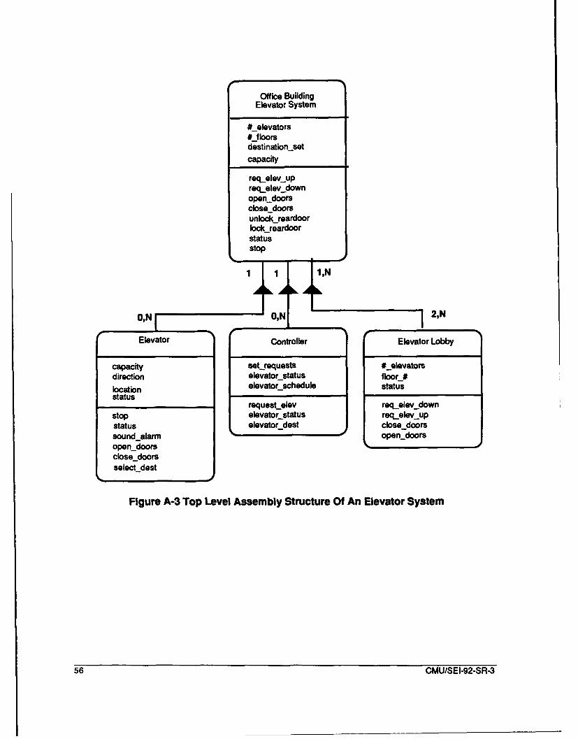
Office BuildingElevator System
#_elevators#_floorsdestination-setcapacity
reqelev.upreq__elev downopendoorsclosedoorsunlock reardoorlockreardoorstatusstop
1 1,N
0,NI I,N I I2,N
Elevator Controller Elevator Lobby
capacity set_requests #_elevatomdirection elevatorstatus floor_#location elevatorschedule statusstatus
request elev req_elev downstop elevator status req_elev upstatus elevatordest closedoorssound-alarm open-doorsopendoorsclosedoorsselect dest
Figure A-3 Top Level Assembly Structure Of An Elevator System
56 CMU/SEI-92-SR-3
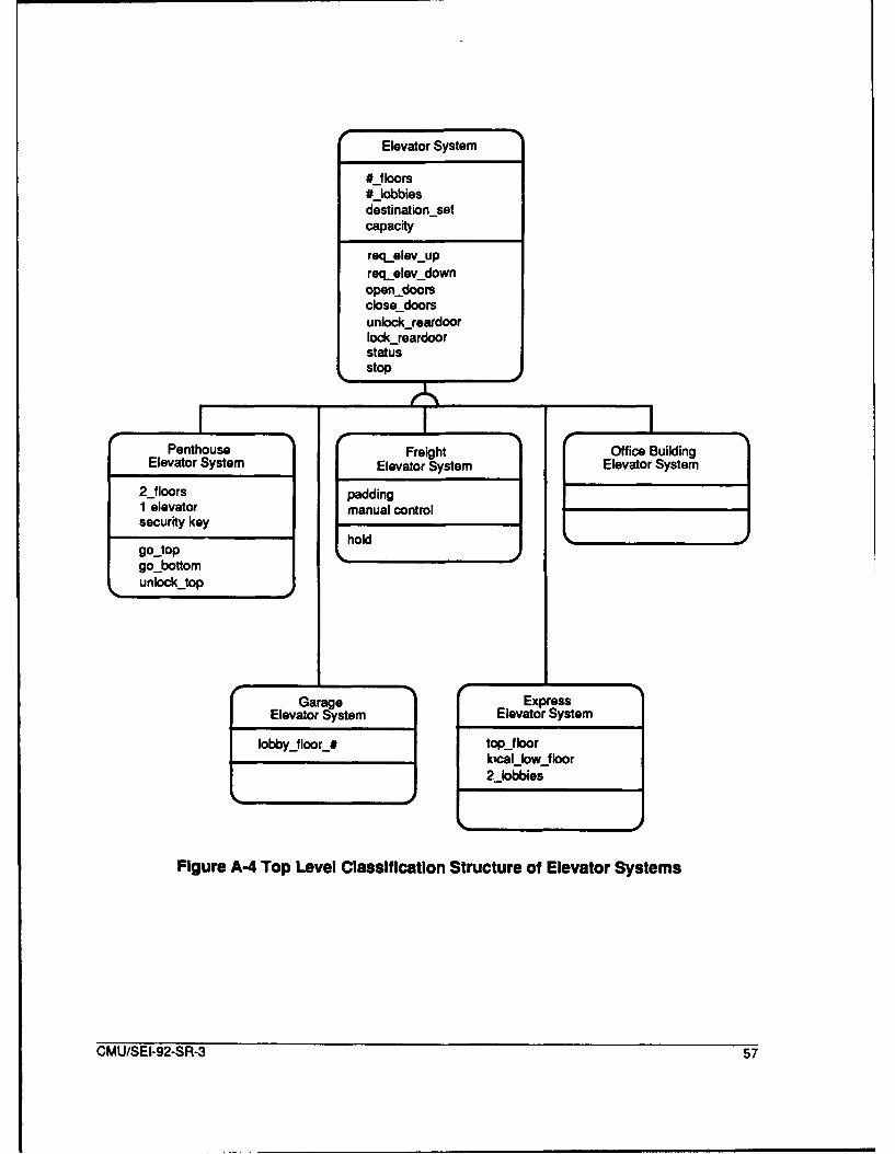
Elevator System
#_floors#_lobbiesdestinationsetcapacity
reqelev-upreqelevdownopendoorsclosedoorsunlockreardoorlockreardoorstatusstop
e 1Penthouse Freight Office Building
Elevator System Elevator System Elevator System
2 2_floors padding1 elevator manual control'security key hli holdgojtopgo-bottomunlockjtop
Garage ExpressElevator System Elevator System
lobbyjloor_# topjloorklcal low floor2_lobbies
Figure A-4 Top Level Classification Structure of Elevator Systems
CMU/SEI-92-SR-3 57
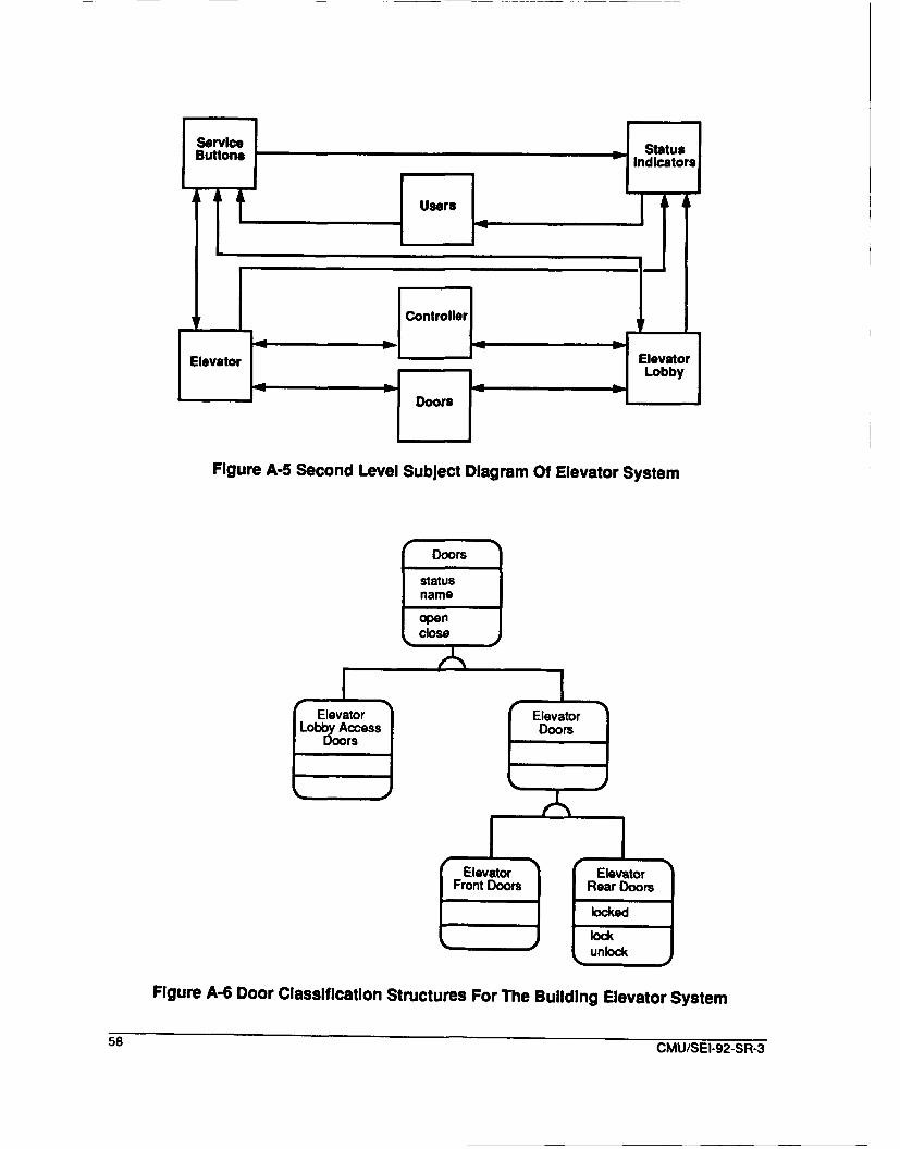
ButtonsIndicatorsI
Users T ýJ
SControllerI
Elevator ElevatorzII~iLobbyI< "-- Doors ••
Figure A-5 Second Level Subject Diagram Of Elevator System
Doors
statusnameopenclose
Elevator E e lvator
Front Doors Rear Doors
lockedlock
unlock
Figure A-6 Door Classification Structures For The Building Elevator System
58 CMU/SEI-92-SR-3
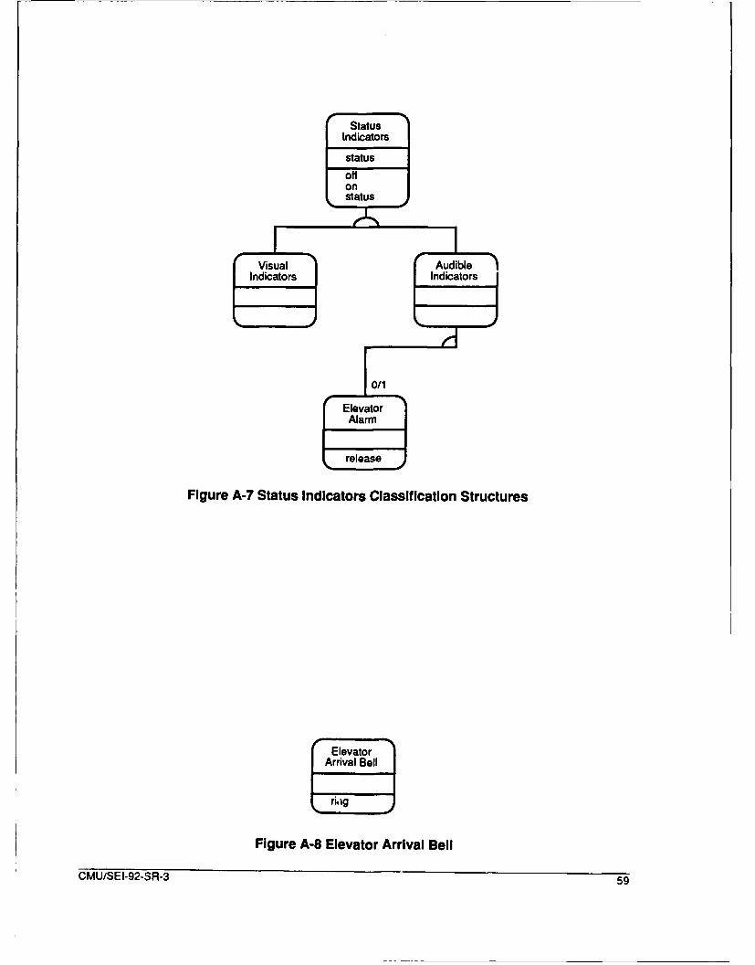
Status
Indicators
statusoffonstatusF vesu.,1 I
Indicators Indicators
0/1
"Evat or
release
Figure A-7 Status Indicators Classification Structures
SElevator "
Arrival Bell
nag
Figure A-8 Elevator Arrival Bell
CMU/SEI-92-SR-3 59

ServiceButton
press
Stop Open Doors Close DoorsButton Button
pressset
Sreset
Elevator Elevator DestinationAlarm Request SelectionButton Button Bto
relea~se
Figure A-9 Service Button Classification Structures
60 CMU/SEI-92-SR-3
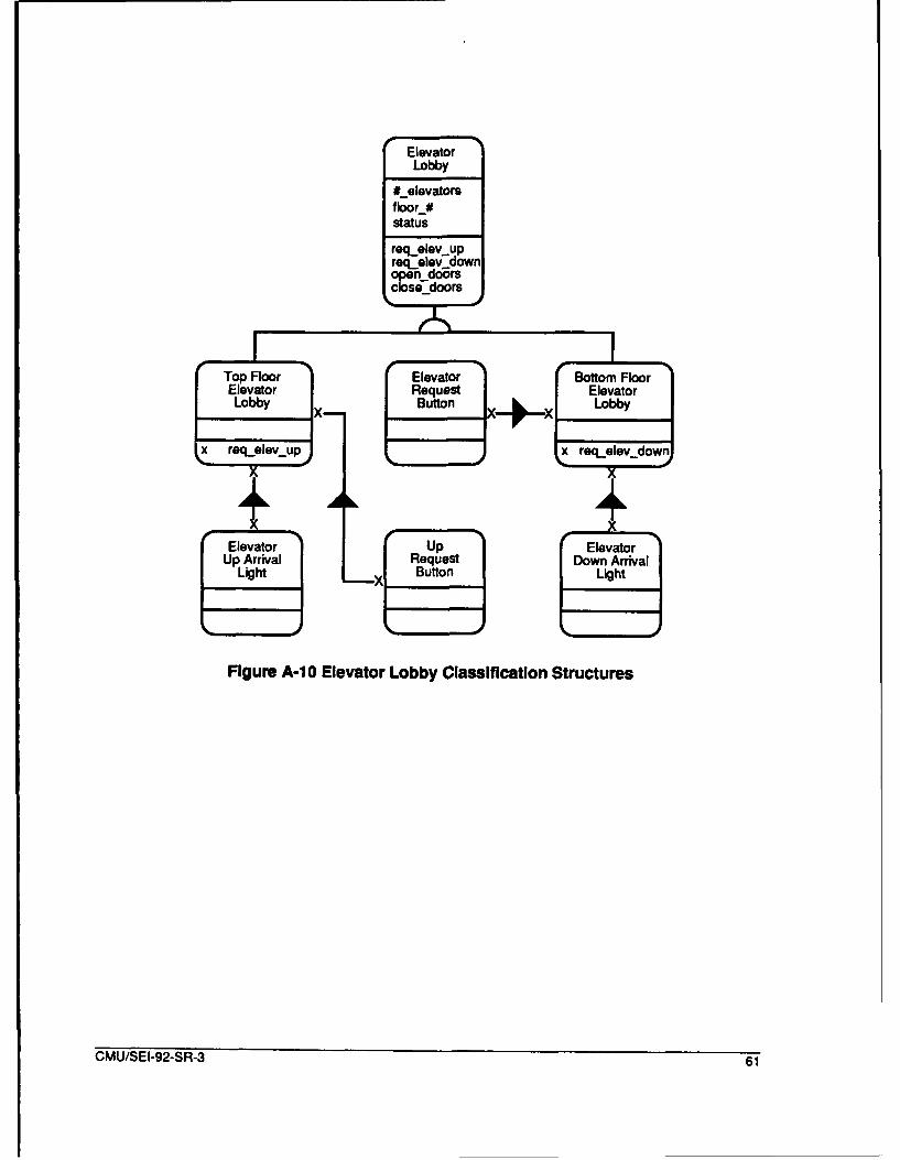
Elevator
Lobby
#_elevatorsfloor_#status
reqelev upreq_elev'downopen doorsclose-doors
-! I
Elevator Request ElevatorLobby X- Button X_* X Lobby
x rea, elev._up rea._elev._dow
X X
Up Arrival Request Down ArrivalLight L -X Button Light
Figure A-10 Elevator Lobby Classification Structures
CMU/SEI-92-SR-3 61
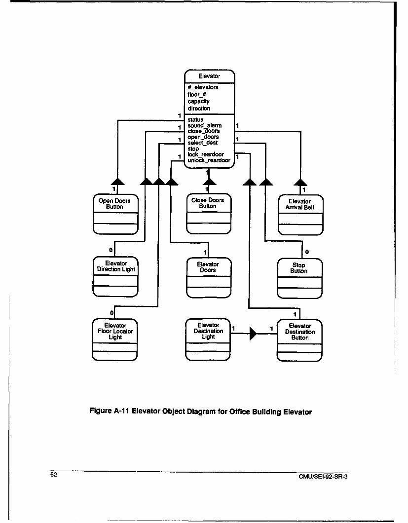
01Elevator
#_elevatorsf loo r_#capacitydirection
OpenenDoors
ButtonButnArvlel
FgreAi Elevator Obec DieagrmtorOfieBldn Elevator
62 GMU/SEI.92-SR-3
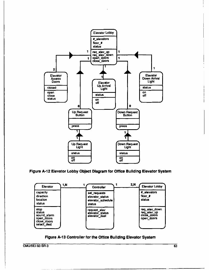
Elevator Lobby
#_elevatorsfloor_#status
1 reqelevup 1 'Ap Rreqt elev downOF I r _so-. cs-_doors
Fiur Ai2 Elvaor Lobb ObetDarm o fieBildin ElvtrSse
Elevator ElevatorAccess Down ArrivalDoors Elevator heLight
closed UpArival status
'open on,close status Off
status onS• ~Off •
stopU Request (elev Roq e q.eej
Button Butown qet
L. press L press
Light Light /
statust statusa/
Figure A-12 Elevator Lobby Object Diagram for Office Building Elevator System
Elevator Controller Elevator Lobbycapacity set~requests #_-elevatorsdirection elevator status f loor_#location elevator-schedule statusstatus status
stop request elev rec~eley downstatus elevatoF status rea~elev upsound alarm elevator_-dest close-doorsopen •oors opon-doorsclose-doorsselec-_dest
Figure A-1 3 Controller for the Office Building Elevator System
CMU/SEI-92-SR-3 63

64 CMU/SEI-92-SR-3
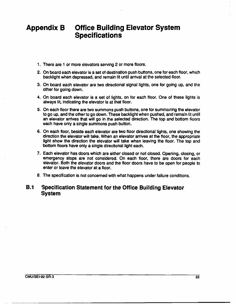
Appendix B Office Building Elevator SystemSpecifications
1. There are 1 or more elevators serving 2 or more floors.
2. On board each elevator is a set of destination push buttons, one for each floor, whichbacklight when depressed, and remain lit until arrival at the selected floor.
3. On board each elevator are two directional signal lights, one for going up, and theother for going down.
4. On board each elevator is a set of lights, on for each floor. One of these lights isalways lit, indicating the elevator is at that floor.
5. On each floor there are two summons push buttons, one for summoning the elevatorto go up, and the other to go down. These backlight when pushed, and remain lit untilan elevator arrives that will go in the selected direction. The top and bottom floorseach have only a single summons push button.
6. On each floor, beside each elevator are two floor directional lights, one showing thedirection the elevator will take. When an elevator arrives at the floor, the appropriatelight show the direction the elevator will take when leaving the floor. The top andbottom floors have only a single directional light each.
7. Each elevator has doors which are either closed or not closed. Opening, closing, oremergency stops are not considered. On each floor, there are doors for eachelevator. Both the elevator doors and the floor doors have to be open for people toenter or leave the elevator at a floor.
8. The specification is not concerned with what happens under failure conditions.
BA1 Specification Statement for the Office Building ElevatorSystem
CMU/SEI-92-SR-3 65

Specification: Elevator Lobby
definitionData# elevators: Integer range (1 ... max # of elevators)
/*The number of elevator which are accessible fromthe lobby
Floor #: Integer range (1 ... 102)/*The floor number where the elevator lobby is
located.
externalSystemlnput: Inputs are received from the Up and DownRequest Buttons.
externalSystemOutput: On and off messages are send to statusindicators: Elevator Up Arrival Light,Elevator Down Arrival Light, Down RequestLight, and Up Request Light.
InstanceConnectionConstraint
with Controller 1::M, required
with Elevator Lobby Access Doors 1:M, requiredwith Elevator Up Arrival Light 1:M, required
with Elevator Down Arrival Light 1:M, required
with Down Request Button 1:M, required
with Up Request button 1:M, required
stateEventResponse: When Users press UP or Down Request Buttons,these requests are sent to the controllerunless a previous request has been sent.
intent/purpose: Provides a locus of control for elevatordoors, requests, and status indicators.
Service request elevatorup Data flow: None.
Sends requestelevator message to controller, after validation
Service request elevator down Data flow: None.
Sends requestelevator message to controller, after validation
Service close access doors Data flow: None.Sends closedoors message to Elevator Lobby Access Doors
Service openaccessdoors Data flow: None.
Sends opendoors message to Elevator Lobby Access Doors
end specification
B.2 Specification of Elevator Lobby Obiect of Office BuildingElevator System
66 CMUISEI-92-SR-3
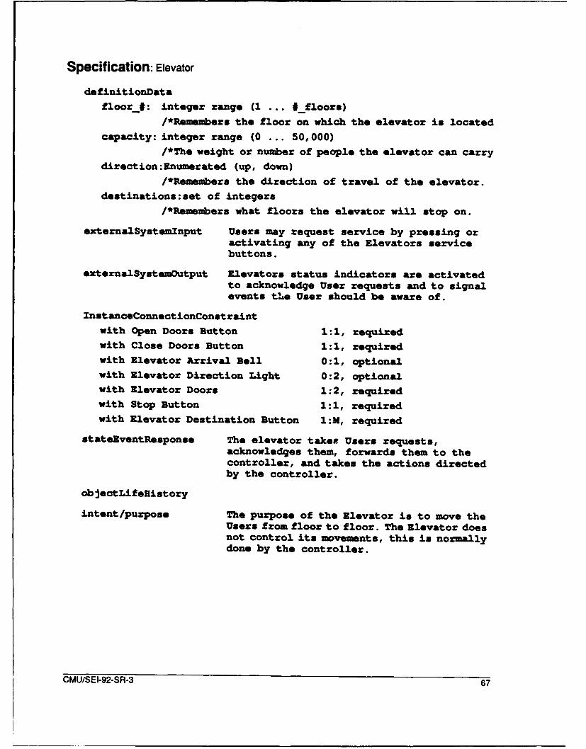
Specification: Elevator
definitionDatafloor#: integer range (1 ... #_floors)
/*Remembers the floor on which the elevator is located
capacity: integer range (0 ... 50,000)/*The weight or number of people the elevator can carry
direction:Enumerated (up, down)/*Remembers the direction of travel of the elevator.
destinations:set of integers
/*Remembers what floors the elevator will stop on.
externalSystemInput Users may request service by pressing oractivating any of the Elevators servicebuttons.
externalSystemOutput Elevators status indicators are activatedto acknowledge User requests and to signalevents tLe User should be aware of.
InstanceConnectionConstraint
with Open Doors Button 1 :1, requiredwith Close Doors Button 1:1, requiredwith Elevator Arrival Bell 0:2., optionalwith Elevator Direction Light 0:2, optionalwith Elevator Doors 1:2, requiredwith Stop Button 1:1, requiredwith Elevator Destination Button 1:M, required
state~ventResponse The elevator taker Users requests,acknowledges them, forwards them to thecontroller, and takes the actions directedby the controller.
ob jectLifeHistory
intent/purpose The purpose of the Elevator is to move theUsers from floor to floor. The Elevator doesnot control its movements, this is normallydone by the controller.
CMU/SEI-92-SR-3 67

Service status Data flow: None.When requested by the controller, or when the status of theelevator changes, the Elevator sends its status to thecontroller.
Service sound alarm Data flow: None.When the User presses the Alarm Button, the Elevator turns onthe alarm. When the User releases the Alarm Button, the Elevatorturns off the alarm.
Service close doors Data flow: None.When the Elevator Doors are open, and either the Users pressesthe Close Door Button or the controller directs the elevator toclose the doors, the doors are closed. This action issynchronized by the Elevator Lobby.
Service opendoors Data flow: None.When the elevator is located at a floor, and either the Userpresses the Open Door Button, or the controller directs theelevator to open the doors, the doors are opened. This action issynchronized by the Elevator Lobby.
Service select dest Data flow: None.The Users presses one of the Elevator Destination Buttons andthe request is sent to the controller, after ensuring that therequest is not currently active.
Service Stop Data Flow: None.When the users activates the stop button, the elevator isstopped, and remains stopped until the User releases the stopbutton.
end specification
B.3 Elevator Specification for Office Building Elevator System
68 CMU/SEI-92-SR-3
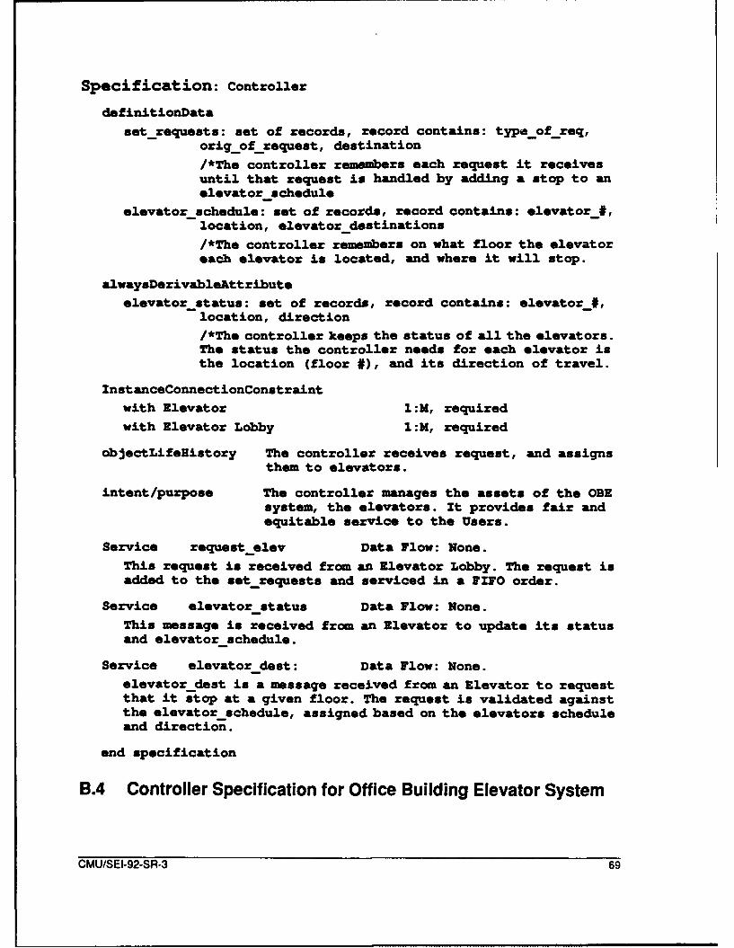
Specification: Controller
definitionDataset_requests: set of records, record contains: typa_of_req,
orig_of_request, destination/*The controller remembers each request it receivesuntil that request is handled by adding a stop to anelevator-schedule
elevatorschedule: set of records, record contains: elevator_#,location, elevator destinations/*The controller remembers on what floor the elevatoreach elevator is located, and where it will stop.
alwaysDerivableAttributeelevatorstatus: set of records, record contains: elevator_#,
location, direction/*The controller keeps the status of all the elevators.The status the controller needs for each elevator isthe location (floor #), and its direction of travel.
InstanceConnectionConstraintwith Elevator 1::M, requiredwith Elevator Lobby 1:M, required
objectLifelistory The controller receives request, and assignsthem to elevators.
intent/purpose The controller manages the assets of the OBEsystem, the elevators. It provides fair andequitable service to the Users.
Service requestelev Data Flow: None.This request is received from an Elevator Lobby. The request isadded to the setrequests and serviced in a FIFO order.
Service elevator status Data Flow: None.This message is received from an Elevator to update its statusand elevatorschedule.
Service elevator dest: Data Flow: None.elevator dest is a message received from an Elevator to requestthat it stop at a given floor. The request is validated againstthe elevatorschedule, assigned based on the elevators scheduleand direction.
end specification
B.4 Controller Specification for Office Building Elevator System
CMU/SEI-92-SR-3 69
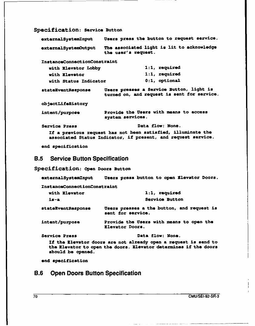
Specification: Service Button
externalSystemlnput Users press the button to request service.
externalSystemOutput The associated light is lit to acknowledgethe user's request.
InstanceConnectionConstraint
with Elevator Lobby 1:1, required
with Elevator 1 :1, required
with Status Indicator 0:1, optional
stateEventResponse Users presses a Service Button, light is
turned on, and request is sent for service.
objectLifeHistory
intent/purpose Provide the Users with means to accesssystem services.
Service Press Data flow: None.
If a previous request has not been satisfied, illuminate theassociated Status Indicator, if present, and request service.
end specification
B.5 Service Button Specification
Specification: Open Doors Button
externalSystemlnput Users press button to open Elevator Doors.
InstanceConnectionConstraint
with Elevator 1:1, required
is-a Service Button
stateEventResponse Users presses a the button, and request issent for service.
intent/purpose Provide the Users with means to open theElevator Doors.
Service Press Data flow: None.
If the Elevator doors are not already open a request is send tothe Elevator to open the doors. Elevator determines if the doorsshould be opened.
end specification
B.6 Open Doors Button Specification
70 CMU/SEI-92-SR-3
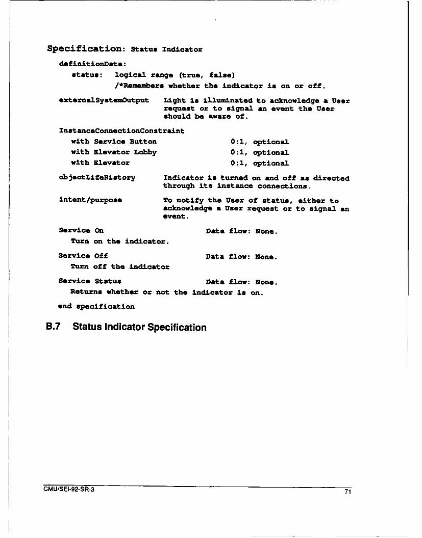
Specification: Status Indicator
definitionData:
status: logical range (true, false)/*Remenbers whether the indicator is on or off.
externalSystemOutput Light is illuminated to acknowledge a Userrequest or to signal an event the Usershould be aware of.
InstanceConnectionConstraint
with Service Button 0:1, optionalwith Elevator Lobby 0:1, optionalwith Elevator 0:1, optional
objectLifenistory Indicator is turned on and off as directedthrough its instance connections.
intent/purpose To notify the User of status, either toacknowledge a User request or to signal anevent.
Service On Data flow: None.
Turn on the indicator.
Service Off Data flow: None.Turn off the indicator
Service Status Data flow: None.Returns whether or not the indicator is on.
end specification
B.7 Status Indicator Specification
CMU/SEI-92-SR-3 71

Specification: Elevator Alarm
externalSystemoutput Sound is generated to alert other buildingoccupants to problems with an elevator.
InstanceConnectionConst raint
with Elevator Alarm Button 1:1, required.
intent/purpose The means for the User to signal a problem.
Service On/Off Data flow: None.
Turn on/off the alarm.
end specification
B.8 Elevator Alarm Specification
Specification: Doors
descriptiveAttributeName: String range (1 ... 32) characters
/*used to distinguish between different doors
definitionDatastatus: enumerate range (open, closed)
/*Maintains if the doors are open or closed.
externalSystemOutput When directed the Doors are open and closed.
InstanceConnectionConstraintwith Elevator Lobby 1:1, required
with Elevator 1:1, requiredstateEventResponse When User presses Open/Close Doors Button,
or when directed, Doors are opened/closed.
intent/purpose The Doors control access to the elevators.
Service open/close Data flow: None.
When directed, the Doors are opened/closed.
Service status Data flow: None.
When requested or when the status has changed, this message issent to the Elevator or Elevator Lobby as appropriate.
end specification
B.9 Door Specification for Office Building Elevator System
72 CMU/SEI-92-SR-3

Specification: Elevator Lobby Access Doors
descriptiveAtt ribute
Name: String range (1 ... 32) characters/*used to distinguish between different doors
definitionData
status: enumerate range (open, closed)/*Maintains if the doors are open or closed.
externalSystemOutput When directed by Elevator Lobby the Doorsare open and closed.
InstanceConnectionConstraintwith Elevator Lobby 1:1, required
stateEventResponse When the Elevator arrives at the floor, thecontroller directs both the Elevator andthe Elevator Lobby to open the doorsassociated with the Elevator. When theElevator Lobby Access Doors in the lobbysense, the Elevator Doors opening, theElevator Lobby Access Doors also open.
intent/purpose The Doors control access to the elevators.
Service open Data flow: None.
When directed, the Doors sre opened.
Service close Data flow: None.When directed, the Doors are closed.
Service status Data flow: None.When requested or when the status has changed, this message issent to the Elevator Lobby.
end specification
B.1 0 Elevator Lobby Access Door Specification
CMU/SEI-92-SR-3 73
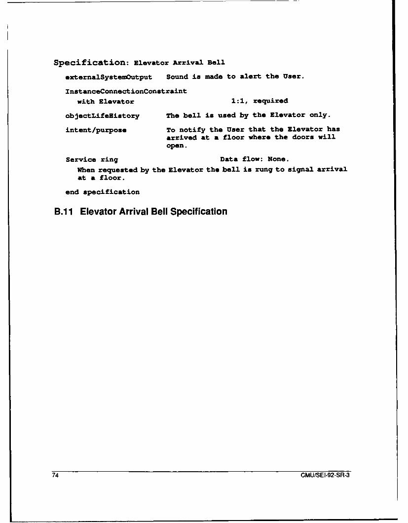
Specification: Elevator Arrival Bell
externalSystemOutput Sound in made to alert the User.
InstanceConnectionConstraintwith Elevator 1:1, required
objectLifegistory The bell is used by the Elevator only.
intent/purpose To notify the User that the Elevator hasarrived at a floor where the doors willopen.
Service ring Data flow: None.
When requested by the Elevator the bell is rung to signal arrivalat a floor.
end specification
B.11 Elevator Arrival Bell Specification
74 CMU/SEI-92-SR-3
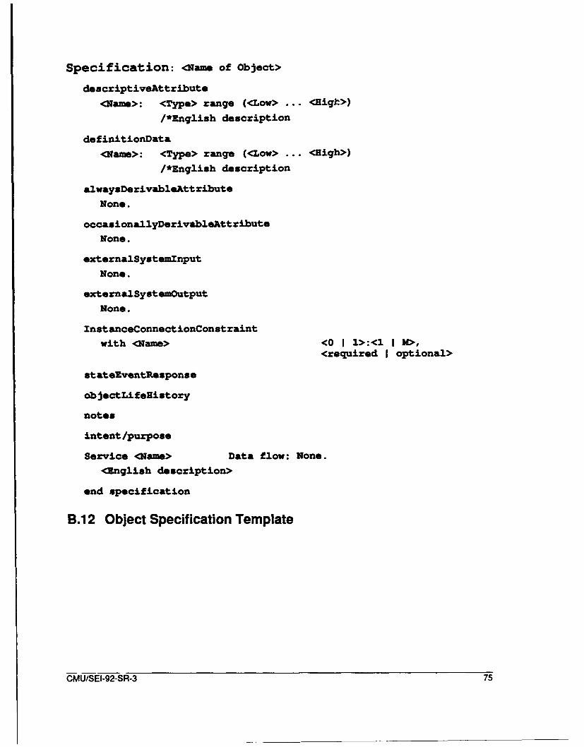
Specification: <Name of Object>
descriptiveAttribute<Nanm>: <Type> range (<Low> ... <Bigk>)
/*English description
de finitionData
<Name>: <Type> range (<Low> ... <High>)/*English description
alwaysDerivableAttribute
None.
occasionallyDerivableAttributeNone.
externalSystemlnput
None.
externalSystemOutputNone.
InstanceConnectionConstraintwith <Name> <0 I 1>:<1 I M>,
<required I optional>
stateRventResponse
ob jectLifelistory
notes
intent/purpose
Service <Name> Data flow: None.
<English description>
end specification
B.12 Object Specification Template
CMU/SEI-92-SR-3 75
76 CMU/SEI-92-SR-3
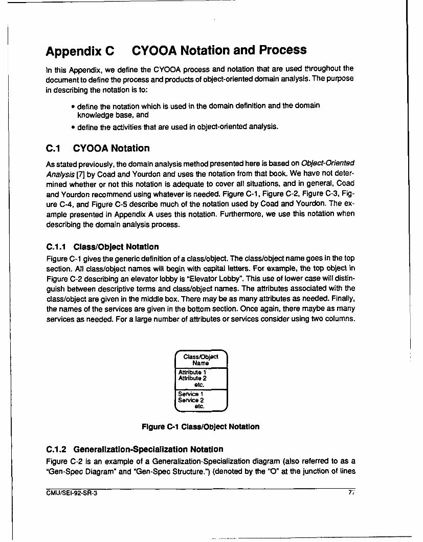
Appendix C CYOOA Notation and Process
In this Appendix, we define the CYOOA process and notation that are used throughout the
document to define the process and products of object-oriented domain analysis. The purpose
in describing the notation is to:
"* define the notation which is used in the domain definition and the domainknowledge base, and
"* define the activities that are used in object-oriented analysis.
C.1 CYOOA Notation
As stated previously, the domain analysis method presented here is based on Object-OrientedAnalysis [7] by Coad and Yourdon and uses the notation from that book. We have not deter-mined whether or not this notation is adequate to cover all situations, and in general, Coadand Yourdon recommend using whatever is needed. Figure C-1, Figure C-2, Figure C-3, Fig-ure C-4, and Figure C-5 describe much of the notation used by Coad and Yourdon. The ex-ample presented in Appendix A uses this notation. Furthermore, we use this notation whendescribing the domain analysis process.
C.1.1 Class/Object Notation
Figure C-1 gives the generic definition of a class/object. The class/object name goes in the topsection. All class/object names will begin with capital letters. For example, the top object inFigure C-2 describing an elevator lobby is "Elevator Lobby". This use of lower case will distin-guish between descriptive terms and class/object names. The attributes associated with theclass/object are given in the middle box. There may be as many attributes as needed. Finally,the names of the services are given in the bottom section. Once again, there maybe as manyservices as needed. For a large number of attributes or services consider using two columns.
Class/ObjectName
Attribute 1Attribute 2
etc.Service 1Service 2
etc.
Figure C-1 Class/Object Notation
C.11.2 Generalization-Specialization Notation
Figure C-2 is an example of a Generalization-Specialization diagram (also referred to as a"Gen-Spec Diagram" and "Gen-Spec Structure.") (denoted by the "0" at the junction of lines
CMU/SEI-92-SR-3 7'
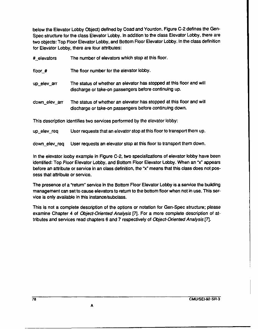
below the Elevator Lobby Object) defined by Coad and Yourdon. Figure C-2 defines the Gen-
Spec structure for the class Elevator Lobby. In addition to the class Elevator Lobby, there are
two objects: Top Floor Elevator Lobby, and Bottom Floor Elevator Lobby. In the class definitionfor Elevator Lobby, there are four attributes:
#_elevators The number of elevators which stop at this floor.
floor_# The floor number for the elevator lobby.
upelevarr The status of whether an elevator has stopped at this floor and willdischarge or take-on passengers before continuing up.
downelevarr The status of whether an elevator has stopped at this floor and will
discharge or take-on passengers before continuing down.
This description identifies two services performed by the elevator lobby:
upelevireq User requests that an elevator stop at this floor to transport them up.
downelevreq User requests an elevator stop at this floor to transport them down.
In the elevator lobby example in Figure C-2, two specializations of elevator lobby have beenidentified: Top Floor Elevator Lobby, and Bottom Floor Elevator Lobby. When an "x" appearsbefore an attribute or service in an class definition, the "x" means that this class does not pos-sess that attribute or service.
The presence of a "return" service in the Bottom Floor Elevator Lobby is a service the buildingmanagement can set to cause elevators to return to the bottom floor when not in use. This ser-vice is only available in this instance/subclass.
This is not a complete description of the options or notation for Gen-Spec structure; pleaseexamine Chapter 4 of Object-Oriented Analysis [7]. For a more complete description of at-tributes and services read chapters 6 and 7 respectively of Object-Oriented Analysis [7].
78 CMUISEI-92-SR-3
A
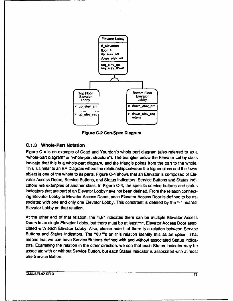
"Elevator Lobby
#_elevatorsfloor #upi1evarrdownelevarr
reqelev upreq_elev-down
Top Floor Botto3mFloor"Elevator ElevatorLobby Lobby
x up_telev_arr ax downtelepn arr
x up._elev_req x down t eleva_req
J return
Figure C-2 Gen-Spec Diagram
C.1.3 Whole-Part Notation
Figure C-4 is an example of Coad and Yourdon's whole-part diagram (also referred to as a"whole-patd diagram" or"whole-part structure"). The triangles below the Elevator Lobby classindicate that this is a whole-part diagram, and the triangle points from the part to the whole.This is similar to an ER Diagram wheret therelmust betwlea the higher class and the lowerobject is one of the whole to its parts. Figure C-4 shows that an Elevator is composed of Ele-vator Access Doors, Service Buttons, and Status Indicators. Service Buttons and Status Indi-cators are examples of another class. In Figure CS the specific service buttons and statusindicators that are part of an Elevator Lobby have not been defined. From the relation connect-ing Elevator Lobby to Elevator Access Doors, each Elevator Access Door is defined to be as-
sociated with one and only one Elevator Lobby. This constraint is defined by the -i" nearestElevator Lobby on that relation.
At the other end of that relation, the "i,N" indicates there can be multiple Elevator AccessDoors in an single Elevator Lobby, but there must be at least"1if, Elevator Access Door asso-ciated with each Elevator Lobby. Also, please note that there is a relation between ServiceButtons and Status Indicators. The "O,1'"s on this relation identity this as an option. Thatmeans that we can have Service Buttons defined with and without associated Status Indica-tors. Examining the relation in the other direction, we see that each Status Indicator may beassociate with or without Service Button, but each Status Indicator is associated with at most
one Service Button.
CMU/SEI-92-SR-3 79
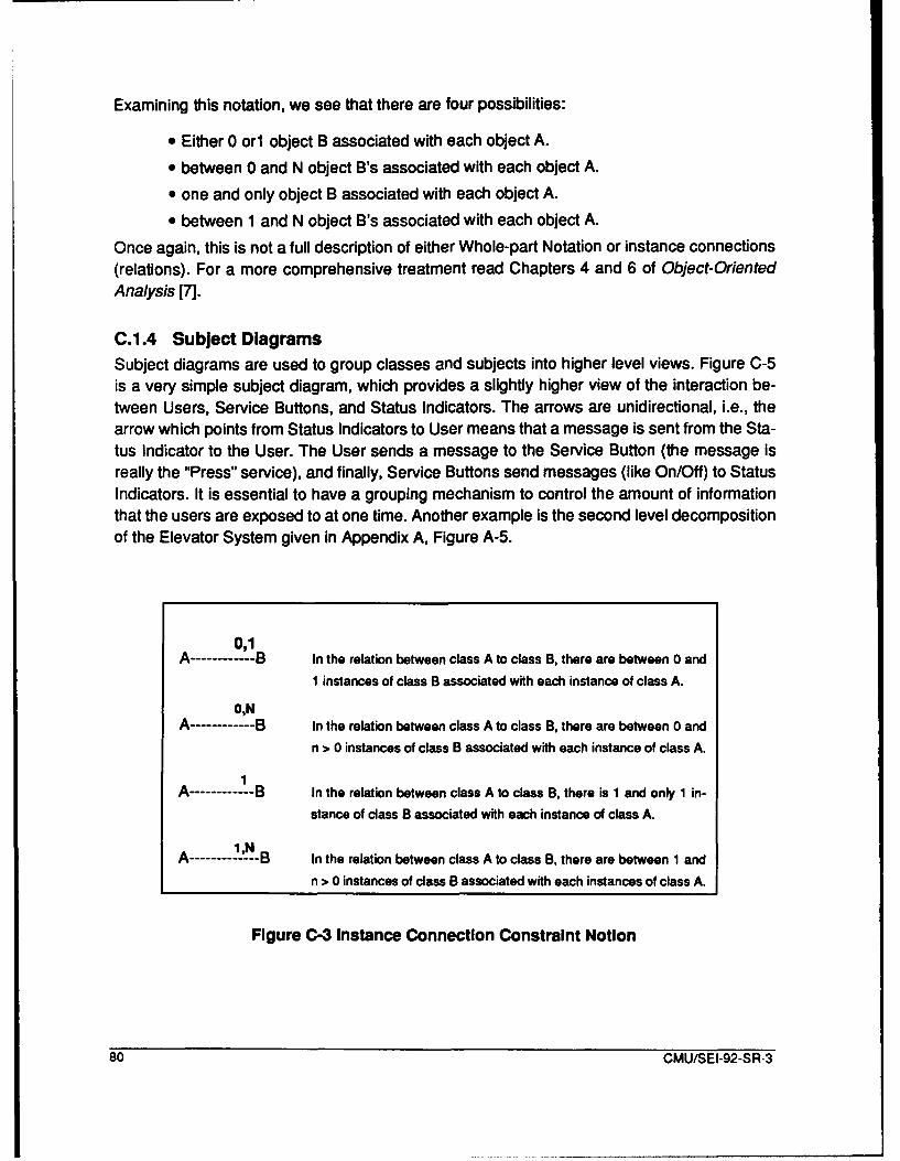
Examining this notation, we see that there are four possibilities:
* Either 0 orn object B associated with each object A.
* between 0 and N object B's associated with each object A.
* one and only object B associated with each object A.
* between 1 and N object B's associated with each object A.
Once again, this is not a full description of either Whole-part Notation or instance connections(relations). For a more comprehensive treatment read Chapters 4 and 6 of Object-OrientedAnalysis [7].
C.11.4 Subject DiagramsSubject diagrams are used to group classes and subjects into higher level views. Figure C-5is a very simple subject diagram, which provides a slightly higher view of the interaction be-tween Users, Service Buttons, and Status Indicators. The arrows are unidirectional, i.e., thearrow which points from Status Indicators to User means that a message is sent from the Sta-tus Indicator to the User. The User sends a message to the Service Button (the message isreally the "Press" service), and finally, Service Buttons send messages (like On/Off) to StatusIndicators. It is essential to have a grouping mechanism to control the amount of informationthat the users are exposed to at one time. Another example is the second level decompositionof the Elevator System given in Appendix A, Figure A-5.
0,1
A ------ B In the relation between class A to class B, there are between 0 andI instances of class B associated with each instance of class A.
0,NA ------ B In the relation between class A to class B, there are between 0 and
n > 0 instances of class B associated with each instance of class A.
1A------ B In the relation between class A to class B, there is I and only 1 in-
stance of class B associated with each instance of class A.
1iNA ------ B In the relation between class A to class B, there are between 1 and
n > 0 instances of class B associated with each instances of class A.
Figure C-3 Instance Connection Constraint Notion
80 CMU/SEI-92-SR-3
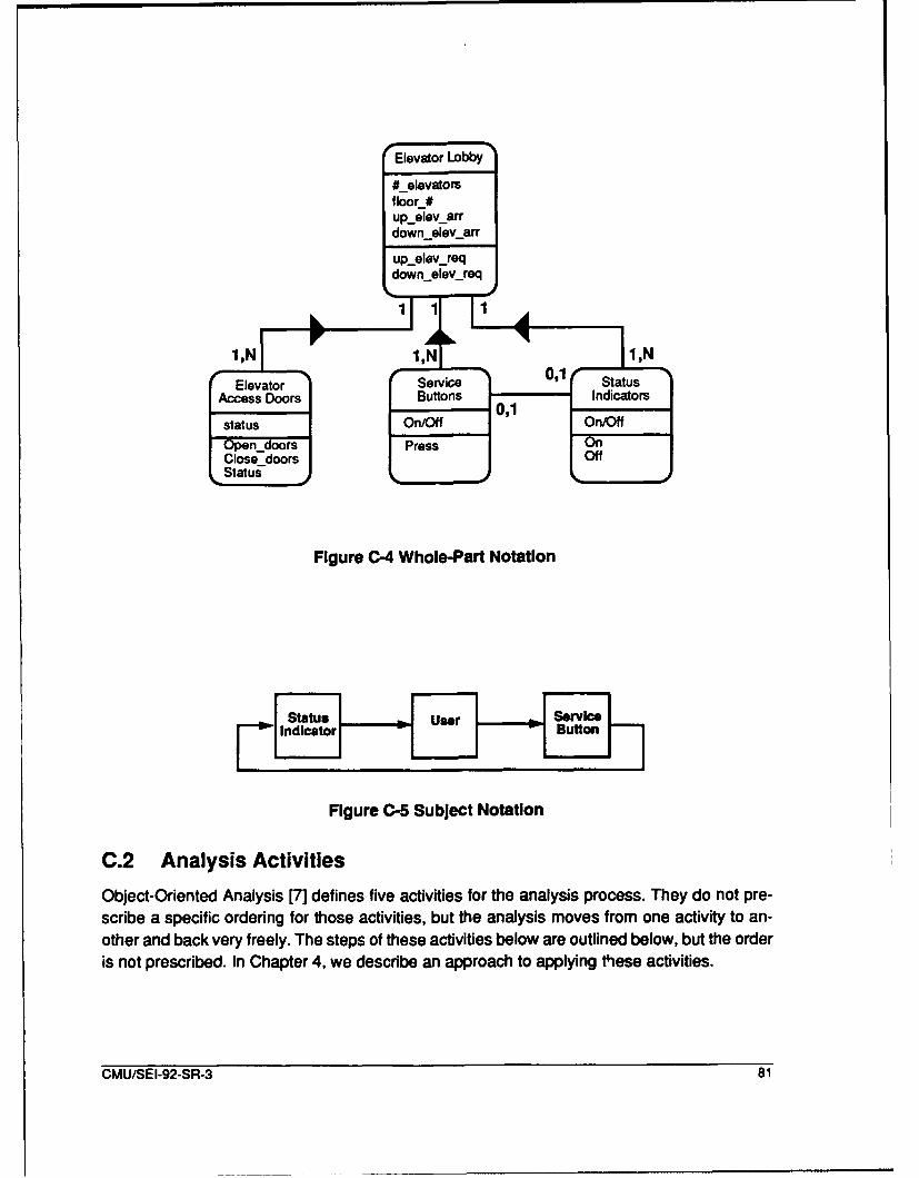
Elevator Lobby
#_elevatorsfloor_#upeievarrdownelev._arr
upelev_reqdown 9elev_req
1,NI 1,01 1,N
Elevator Service StatusNtiAccess Doors Buttons Indicators
status On/Off On/Off
Open._doors Press OnClose-doors OffStatus-
Figure C-4 Whole-Part Notation
I ndicator H fluf Butto
Figure C-5 Subject Notation
C.2 Analysis Activities
Object-Oriented Analysis [7] defines five activities for the analysis process. They do not pre-scribe a specific ordering for those activities, but the analysis moves from one activity to an-other and back very freely. The steps of these activities below are outlined below, but the orderis not prescribed. In Chapter 4, we describe an approach to applying these activities.
CMU/SEI-92-SR-3 81

C.2.1 Identify ClassesA Class is an encapsulation and an abstraction: an encapsulation of attributes and exclusiveservices on those attributes and an abstraction of the problem space, representing one ormore occurrences of something in the problem space. To find Classes, look at problem space,text, and pictures (previous systems).
What to look for:
1. Gen-Spec and Whole-part structure (see C.2.2).
2. Other Systems that the system under development (SUD) will interact with.
3. Devices (documents, formal) that the SUD will interact with.
4. Events that must be remembered by the SUD.5. Roles played by humans who interact with the SUD and about whom information is
kept by the system.
6. Locations (physical), offices, or sites that the system under consideration will needknowledge of.
7. Organizational units that humans belong to.
What to consider:
1. Does the SUD need to remember anything about this potential Class?
2. Does the system need to provide processing on behalf of this Class?
3. Does the Class have more than one attribute?
4. Are there attributes which apply to all instances of an Class?
5. Are there a common set of services for all instances?
6. Essential requirements - Are there requirements that system must have, regardlessof the technology used for implementation?
What to challenge:
1. Unneeded remembrance - If a system does not need to hold information about a realworld thing over time or provide Services for it, remove the Class.
2. Unneeded Services - If a system does not need to hold information about a real worldthing over time or provide Services for it, remove the Class.
3. Single occurrences - If there is only one occurrence of a Class try to identify Classeswith the same attributes and services and just use one of them.
4. Derived results - Examine the model for derived results, e.g., customer's age in asystem that already remembers the customer's date of birth.
82 CMU/SEI-92-SR-3

How to name:
1. Use a singular noun, or adjective+noun
2. Use a name that describes a single instance of a Class
3. Use standard subject matter vocabulary - match the names to the domain expert'svocabulary.
4. Use readable names, with upper and lower case; don't use prefix and suffixes.
C.2.2 Identify Structure
Structures represent complexity in the problem space:
1. Generalization-Specialization (Gen-Spec) Structure represents class-member orga-nization, reflecting generalization-specialization.
2. Whole-Part Structure represents aggregation, reflecting whole and component parts.
How to define:
1. Gen-Spec Structure: Consider each Class as a generalization, then as a specializa-tion. Does the specialization reflect meaningful real-world specialization, and is itwithin the problem space?
2. Whole-part Structure: Consider each Class as a whole, then as a component part.Examine the next higher level Class to check problem space and scope.
Checks: Is this real-world structure, within the problem space, and within thescope of the domain?
C.2.3 Identifying SubjectsThis is a mechanism for controlling how much of a model a reader considers at one time.
How to define:
1. Add a subject for each Class.
2. Add a Subject for each structure.
3. Group Subjects if more than 7 +- 2.
4. Combine tightly coupled subjects to provide a better overview after attributes andservices are defined.
5. For very large projects, iterate quickly over Classes, Structure, and Subjects.
Show communications between Subjects with connections, and number the Subjects.
C.2.4 Defining Attributes
Attributes are data elements used to describe an instance of a Class or Gen-Spec Structure.
How to define Attributes:
CMU/SEI-92-SR-3 83
1. Return to the problem space description and the user to get the values (state) of the
domain objects.
2. Insure attributes really model reality.
3. Identify each Attribute at the atomic level, e.g. address, not street, city, state, and zipcode.
Position the Attributes:
1. Place the attribute using inheritance in Gen-Spec Structures.
2. Place at the highest level where it applies to most specializations.
3. Add specializations when they only exist in the specialization.
Identify and Define instance connections:
1. Add instance connection lines between Classes to identify problem space connec-tions (relationships).
2. Add instances to specializations if the instance doesn't apply to ALL specializations.
3. Define multiplicity, i.e. define whether the instance is 1:1 or 1 :m for both ends of theinstance. Add a "1" for 1-1; add "N" for multiples.
4. Define participation, is the instance connection mandatory or optional for each endof the connection. Add "1'" for required; "0" for optional.
5. Check for special cases
a. Connections across three or more Classes. Add an instance of A toC, if A to B or B to C is optional.
b. Many-to-many instance Connections. Examine the connection todetermine if the attributes describe the connection between theClasses. If so, then add a Class of things remembered.
c. Instance Connections between instances of the same Class or Gen-Spec Structure. If the instance connection has descriptive Attributes,then introduce a new Class to capture the Instance Connection.
d. Multiple Instance Connections between two Classes or Gen-SpecStructures. Examine the meaning of the two connections, capture theunderlying semantic distinction with one or more Attributes, andremove one instance.
Class and connection identifiers are defined by the system during design phase since real-world identifiers will repeat.
Revise Classes:
1. Attributes with value of "Not Applicable". If some Attributes do not apply to all instanc-es, then consider adding more Gen-Spec Structure.
2. Single Attributes. If a Class or an instance of a Gen-Spec Structure has only a singleAttribute, then the model can be revised to reflect a higher level of abstraction.
84 CMU/SEI-92-SR-3
3. Repeated values for one or more Attributes. If an attribute can simultaneously havemore than value, then consider adding a new Class.
4. Adaptation Parameters. For site specific data, add a site Class with installationAttributes. For operational data, parameterize the range Attributes.
Specify the Attributes:
1. For each Class or structure, specify the Attributes with names and descriptions.
2. For each Class or Structure, identify each category of attribute (e.g., descriptive,definition, always derivable, occasionally derivable).
Specify instance connection constraints. For each Class and structure, specify the instance
connection constraints.
C.2.5 Defining Services
Services are the processing to be performed upon receipt of a message.
How to define Services:
1. Identify the Services (Primary Strategy):
a. Occur (instance add, change, delete, and select)
b. Calculate Services - calculate results for an instance or on behalf ofanother instance.
c. Monitor Services - performs on-going monitor of an external system,device, or user.
2. Identify the Services (Secondary Strategies)
a. Object Life History:
i. Define the basic Object Life History sequence.
ii. Check for variations on each step.
iii. Add to the basic sequence.
iv. Add Services.
b. State-Event Response:
i. Define major system states.
ii. For each state, list the external events and required responses.
iii. Expand the Services (and Message Connections).
3. Identify the Message Connections. Begin by adding Message Connections betweenClasses and Gen-Spec Structures already connected with Instance connections.Arrows are unidirectional (meaning send, receive, and response).
CMU/SEI-92-SR-3 85
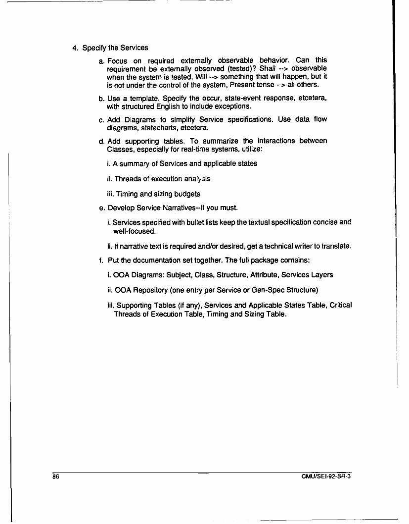
4. Specify the Services
a. Focus on required externally observable behavior. Can thisrequirement be externally observed (tested)? Shall --> observablewhen the system is tested, Will --> something that will happen, but itis not under the control of the system, Present tense --> all others.
b. Use a template. Specify the occur, state-event response, etcetera,with structured English to include exceptions.
c. Add Diagrams to simplify Service specifications. Use data flowdiagrams, statecharts, etcetera.
d. Add supporting tables. To summarize the interactions betweenClasses, especially for real-time systems, utilize:
i. A summary of Services and applicable states
ii. Threads of execution analy3is
iii. Timing and sizing budgets
e. Develop Service Narratives--If you must.
i. Services specified with bullet lists keep the textual specification concise andwell-focused.
ii. If narrative text is required and/or desired, get a technical writer to translate.
f. Put the documentation set together. The full package contains:
i. OOA Diagrams: Subject, Class, Structure, Attribute, Services Layers
ii. OOA Repository (one entry per Service or Gen-Spec Structure)
iii. Supporting Tables (if any), Services and Applicable States Table, CriticalThreads of Execution Table, Timing and Sizing Table.
86 CMU/SEI-92-SR-3

Glossary
We would prefer to have more commonly accepted definitions, but the process of domain analysis is insufficientlymature for this agreement.
attribute a data element used to describe an instance of an object or classifi-cation structure
application engineering the process of analyzing, specifying, designing, implementing, inte-grating, and testing software (systems) based on the existence of areuse-based software engineering methodology, domain knowledge,domain assets, and reuse tools
class a collection of objects which can be described with the same at-tributes and services
domain 1. a territory or range of rule or control: realm; 2. a sphere of concernor function; field: the domain of history
domain analysis the process of identifying, collecting, organizing, analyzing, and rep-resenting important entities in a domain model from the study of ex-isting systems, underlying theory, emerging technology, anddevelopment histories within the domain of interest
domain engineering the process of identifying candidate domains from a cost perfor-mance analysis, selecting domain analysis, design, and implementa-tion methods, performing domain analysis, domain design, anddomain implementation, and creating domain assets to support Re-use-Based Software Engineering (Application Engineering)
domain entity an object, relationship, operator, process, fact or rule of a domain [14]
domain implementation 1. the construction of a software architecture, components, methods,and tools and their supporting documentation to solve the problemsof system/subsystem development by the application of the knowl-edge in the domain model; 2. the process of building reusable soft-ware objects using domain analysis work products (domain models,domain languages, and taxonomies); 3. the creation of domain lan-guage processors and allied tools
domain model a formal, concise, representation of a domain [14]
entity 1. the fact of existence; being; 2. something that exists independent-ly, not relative to other things; 3. a particular and discrete unit; an en-tirety
gen-spec diagram a representation of class-member organization, reflecting generaliza-tion-specialization
model/requirements transformation the process of converting the domain model into requirements thatare defined by DOD-STD 2167A Data Item Description DI-MCCR80025A
CMU/SEI-92-SR-3 87
object an abstraction of something in the real world, reflecting the capabili-ties of a system to keep information about it, interact with it, or both;an encapsulation of attribute values and their exclusive services.
reusable software object Life-cycle products that are created during the software developmentprocess that are needed to operate, maintain, and upgrade deliver-able avionics during its lifetime and that have the potential for reuse.The objects may include, but are not limited to: requirements specifi-cations, design documents (both top level and detailed), source andobject code, test specifications, test code, test support data, usersmanuals, programmer notes and algorithms.
service a processing to be performed upon receipt of a message by an object
software architecture the packaging of functions and objects, their interfaces, and controlto implement applications in a domain
whole-part diagram a representation of aggregation, reflecting the whole and its compo-nent parts
88 CMU/SEI-92-SR-3

References
[1] Adelson, B. and Soloway, E. "The Role of Domain Experience in Software De-sign." IEEE Transactions on Software Engineering SE- 1I(11) (November1985): 1351-1360.
[2] Alford, Mack W. "A Requirements Engineering Methodology for Real-Time Pro-cessing Requirements." IEEE Transactions on Software Engineering 3(1)(January 1977): 60-69.
[3] Arango, G. and Prieto-Diaz, R. Domain Analysis: Concepts and Research Di-rections. 1990.
[4] Bach, William W. "Is Ada Really an Object-Oriented Programming Language."Journal of Pascal, Ada & Modula-2 8(2), (Mar/Apr, 1989).
[5] Basili, V. "Viewing Maintenance as Reuse-Oriented Software Development."IEEE Software 7(1) (January 1990): 19-25.
[6] Campbell Jr., G., Faulk, S., and Weiss, D. Introduction to Synthesis. (IN-TROSYNTHESIS-90019-N) Hemdon, Virginia: SPC, June, 1990.
[7] Coad, P., and Yourdon, E. Object-Oriented Analysis. Englewood Cliffs, NewJersey: Prentice-Hall, 1990.
[8] Coad, Peter. NewAdvances in Object-OrientedAnalysis. (IV-400). Austin, Tex-as, 1990.
[9] CTA, Incorporated. JIA WG Reuse System Description. (CDRL B004 (GMAX)).Ridgecrest, California: CTA, Incorporated, September 1990.
[10] CTA, Incorporated. JIAWG Prototype Library Test Results. (CDRL B004(GMBF)). Ridgecrest, California: CTA, Incorporated, September 1990.
[11] D'lppolito, Richard S. "Using Models in Software Engineering." Proceedings ofTri-Ada '89 (October 1989): 256-265.
[12] Department of Defense. Defense System Software Standard. Washington,D.C.: Department of Defense, 1988.
[13] Gilroy, Kathleen A., Comer, Edward R., J. Kaye Grau, J. Kaye, and Merlet,Patrick J. Impact of Domain Analysis on Reuse Methods. Indialantic, Florida:Software Productivity Solutions, 1989.
[14] Gish, James W. and Prieto-Diaz, Ruben. Domain Analysis: Procedural ModelRefinement and Experimental Proposal. (87-126.05). Waltham, Massachu-setts: GTE Laboratories, April 1988.
CMU/SEI-92-SR-3 89
[151 Harel, David. "On Visual Formalisms." Communications of the ACM31 (5) (May1988): 514-530.
[161 Hoare C. A. R., ed. Internation Series in Computer Science: Object-orientedSoftware Construction. Hemel Hempstead: Prentice Hall, 1988.
[17] Holibaugh, Robert R., Cohen, Sholom G., Kang, Kyo C., and Peterson, Spen-cer. "Reuse: Where to Begin and Why." Proceedings of Tri-Ada '89 (October1989): 266-277.
[18] Lanergan, R.G. and Poynton, B.A. "Reusable Code: The Application Develop-ment Technique for the Future." Proceedings of the IBM SHARE/GUIDE Soft-ware Symposium. (October, 1979).
[19] Lee, K. and Rissman, M. An Object-Oriented Solution Example: A Flight Simu-lator Electrical System. (CMU/SEI-89-TR-5). Pittsburgh, Pennsylvania: Soft-ware Engineering Institute, Carnegie Mellon University, February 1989.
[201 Matsumoto, M. "Reusable Software Parts Paradigm and Automatic ProgramSynthesis Using Them." Proceedings of the National Conference on SoftwareReusability and Maintainability. (September 1986).
[21] McNicholl, Daniel G., et. al. Common Ada Missile Packages (CAMP) - Volume/: Overview and Commonality Study Results. (AFATL-TR-85-93). St. Louis,Missouri: McDonnell Douglas Astronautics Company, May 1986.
[22] McNicholl, D., et. al. Common Ada Missile packages. (AFATL-TR-85-93). EglinAFB, Florida: Air Force Armament Laboratory, May 1986.
[23] McNicholl, D., Palmer, C., and Cohen, S. Common Ada Missile Program--Phase2. (AFATL-TR-88-62). Eglin AFB, Florida: Air Force Armament Labora-tory, November 1988.
[24] Mish, Fredick, ed. Webster's Ninth New Collegiate Dictionary. Springfield, Mas-sachusetts: Merriam-Webster, 1985.
[25] Moore, J. and Bailin, S. Domain Analysis: A Framework for Reuse. Rockville,Maryland: CTA, INCORPORATED, October 1989.
[26] Parnas, D. "Desiging Software for Ease of Extension and Contraction." IEEETransaction on Software Engineering SE-5(2) (March 1979):128-138.
[27] Plinta, C., Lee, K., and Rissman, M. A Model Solution for C31 Message Trans-lation and Validation. (CMU/SEI-89-TR-12), Pittsburgh, Pennsylvania: Soft-ware Engineering Institute, Carnegie Mellon University, December 1989.
90 CMU/SEI-92-SR-3
[28] Prieto-Diaz, Ruben. "Domain Analysis for Reusability." Proceedings of COMP-SAC 87:The Eleventh Annual International Computer Software & ApplicationsConference (October 1987): 23-29.
[29] SPC. A Domain Analysis Process. (DomainAnalysis-90001 -N). Hemdon, Vir-ginia: Software Productivity Consortium, January 1990.
CMU/SEI-92-SR-3 91
92 CMU/SEI-92-SR-3
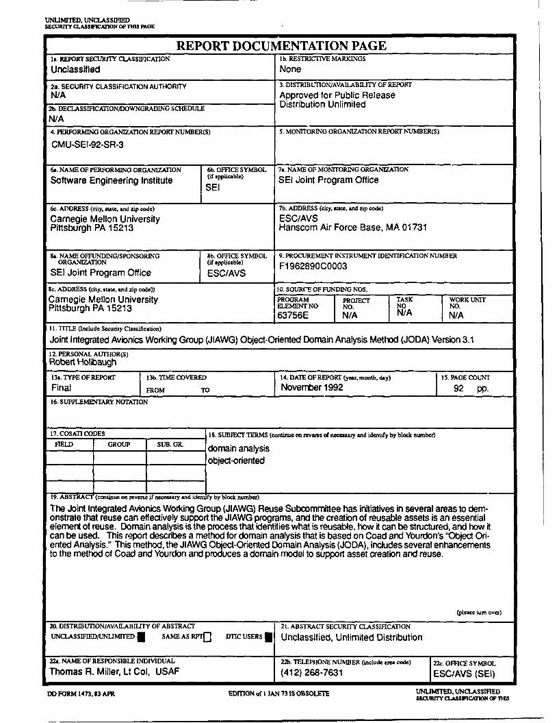
UNLIMrTED. UNCLASSIFIEDS1.•RfrY C. ASSWICATION OIM iGOE
REPORT DOCUMENTATION PAGEIt. REPORT SECURITY CLASSIFICATION lb. RESTRICTIVE MARKINGS
Unclassified None
2a. SECURITY CLASSIFICATION AUTHORITY 3. DISTRIBUTION/AVAILABILITY OF REPORT
N/A Approved for Public Release2b. DECLASSIFICAION/DOWNGRADING SCHEDULE Distribution UnlimitedN/A4. PERFORMING ORGANIZATION REPORT NUMBER(S) 5. MONITORING ORGANIZATION REPORT NUMBER(S)
CMU-SEI-92-SR-3
6(. NAME OF PERFORMING ORGANIZATION 6b. OFFICE SYMBOL 7a. NAME OF MONITORING ORGANIZATION
Software Engineering Institute (if applicable.) SEI Joint Program OfficeSEI
6c. ADDRESS (city, state, and zip code) 7b. ADDRESS (city, state, and zip code)
Carnegie Mellon University ESC/AVSPittsburgh PA 15213 Hanscom Air Force Base, MA 01731
&a. NAME OFFUNDING/SPONSORING 8b. OFFICE SYMBOL 9. PROCUREMENT INSTRUMENT IDENTIFICATION NUMBER
ORGANIZATION (if applicable) F1962890C0003SEI Joint Program Office ESC/AVS
Sc. ADDRESS (city, state, and zip code)) 10. SOURC"E OF FUNDING NOS.
Carnegie Mellon University PROGRAM PROJECT TASK WORK UNITPittsburgh PA 15213 ELEMENT NO NO. NO NO.
63756E N/A N/A N/A11. TITLE (Include Security Classification)
Joint Integrated Avionics Working Group (JIAWG) Object-Oriented Domain Analysis Method (JODA) Version 3.112. PERSONAL AUTHOR(S)Robert Holibaugh
13a. TYPE OF REPORT 13b. TIME COVERED 14. DATE OF REPORT (yea, month, day) 15. PAGE COUNT
Final FROM TO November 1992 92 pp.16, SUPPLEMUETARY NOTATION
17. COSATI CODES 8l. SUBJECT TERMS (continue on reverse of necessary and identify by block number)
FIELD GROUP SUB. GIL domain analysis
_object-oriented
19. ABSTRACT) (continue on reve if necearaay and identify by block number)
The Joint Integrated Avionics Working Group (JIAWG) Reuse Subcommittee has initiatives in several areas to dem-onstrate that reuse can effectively support the JIAWG programs, and the creation of reusable assets is an essentialelement of reuse. Domain analysis is the process that identifies what is reusable, how it can be structured, and how itcan be used. This report describes a method for domain analysis that is based on Coad and Yourdon's "Object Ori-ented Analysis." This method, the JIAWG Object-Oriented Domain Analysis (JODA), includes several enhancementsto the method of Coad and Yourdon and produces a domain model to support asset creation and reuse.
(pleae turn over)20. DISTRIBUTION/AVAILABIUTY OF ABSTRACT 21. ABSTRACT SECURITY CLASSIFICATION
uNc:LAsSIFIED/UNAIMITED N SAME AS RIf DTIc USERS I Unclassified, Unlimited Distribution
22a. NAME OF RESPONSIBLE INDIVIDUAL 22b. TELEPHONE NUMBER (include area code) 22c. OFFICE SYMBOL
Thomas R. Miller, Lt Col, USAF (412) 268-7631 ESCIAVS (SEI)
DD FORM 1473.83 APR EDITION of I JAN 73 IS OBSOLETE UNLIMITED. UNCLASSIFIEDSECURITY aAssIFCATION OF THIS
STRAC" - contnued from pape ane. block 19

![Slide 1 [S2001, Cap. 5] [AC96, Cap. 1] u Functional, non-functional, domain requirements u User requirements u System and software requirements u Requirements](https://img.pdfslide.us/doc/110x75/5542eb4f497959361e8be739/slide-1-s2001-cap-5-ac96-cap-1-u-functional-non-functional-domain-requirements-u-user-requirements-u-system-and-software-requirements-u-requirements.jpg)