Embed Size (px)
Citation preview
AD-AOBO 465 IYDRONAUTICS INC LAUREL MO F/B 13/10TOWBOAT MANEUVERING SIMULATOR. VOLUME 111. THEORETICAL OESCRIPT-ETCtU)MAY 79 E R MILLER OT-CS-840165-A
UNCLASSIFIED 7909-1-VOL-3 USC-D-63-79 NL
I muuuuuuuuIiEEEs///ll//l///,MEN~llll

Report No. CG-D-63.-79 1
TOWBOAT MANEUVERING SIMULATOR
VOLUME III - THEORETICAL DESCRIPTION
00( I E'r
EUGENE R. MILLERj JR.E
FINAL REPORT
MAY 1979
Document is available to the public through theNational Technical Information Service,
Springfield, Virginia 22151
LA-.-.J
Prepared for
U.S. DEPARTMENT OF TRANSPORTATIONUnited States Coast Guard
Office of Research and DevelopmentWashington, D.C. 20590
30
NOTICE
S:. This document is disueminated under the sponsorship of the Departmentof Transportatlon in the interest of information exchange. The UnitedState Government assumes no liability for its contens or use thereof
The contents of this report do not necessarilv reflect the official viewor policy of the Coast Guard; and they do not constitute a standard,spcifcation, or regulation.
This report, or portions thereof may not be used for advertising orsa promotion purposes. Citation of trade names and manufacturersdoa not constitute endorsmnent or approval of such products
II
L •.
ILI
I Iii I I t i
I It
jisr
I a af~ fll, a A'
Ila % 11s1Iii -ABI n UAITnj~j
m ua voi zo om

in, T*6haicel Repo.. Decume.ti.n Peg
2. 5eGveino'. A sse,., . 3. Reqp.g so,' C60e416aN.
D-E:3-792
4 Towboat Maneuvering Simulator May 079Volume IIlyTheoretical Descriptiono e.
(~~Eugene R.- Mill1er, JrY .' 7909-1V~L9. P~M,,*A,,,t,, laO e m ime o iw- .. -P .--- so' N-.. fte N& 41rlTAAJ
Hydronautics, Inc. o--. W., -6-- %a .
Laurel, Maryland T'" DOT-CG-84Pi65-A 4
12. 5eq...n.. Aeegp None ad Ad&*$
U.S. Department of Transportation ep 878- May 079 /United States Coast Guard %,,_._ _ __IL__Office of Research and Development 'f. Agrom-- CodeWashington, 0. C. 20590 _ G-OSA-l
IS. S"016000fory "iie .....
The U. S. Coast Guard's technical representative for the work described hereinwas David A. Walden.
14. A4ba W .. .. .
N-The Towboat Maneuvering Simulator is based on the integration in time ofthe differential equations which describe the motions of the towboat and bargestring in three degrees of freedom, i.e., yaw, sway and surge.
'This volume of the simulator documentation provides a description of thebasic equations of motion included in the simulator and the relationships usedto determine external forces and moments due to a bow thruster and wind. Theseequations are completely general in nature and could be used, with the properhydrodynamic coefficients, to describe the maneuvering of vessels other thantowboats.
17. Key Wosi ' 1. Dsimh..s,. St'. m,' "
Towboat Documentation is available through theManeuvering National Technical Information Service,
Springfield, VA 22161.
19. £eewnep CI o#*$. (e " Aie .ewtl 'U. S0aiele. Cloe. (41 twe e) 21. N.. of Poo 2. Phe"
Unclassified
Pen n DOT P 1700.7 (-n) Iep mdveti of e wmelet d p e. eu"l Aed . 7 Y snd
HYDRONAUTICS, Incorporated
TABLE OF CONTENTS
Page
NOTATION -.. .............................................. i-
1. 0 INTRODUCTION ...................................... 1
2.0 14ATHEMATICAL MODEL................................. 2
3.0 EXTERNAL FORCES .................................. 13
3.1 Bow Thruster ............................... 13
3.2 Wind Forces and Moments ................... 14
3.3 Other External Forces ...................... 17
4.0 CONTROL SYSTEMS .................................. 18
REFERENCES ........................................... 19
Acceaeliou For
Juatifiti on
By--_________
* Ave11l'b111tv C A r.A all wid/or
Ds{ spec l
..........
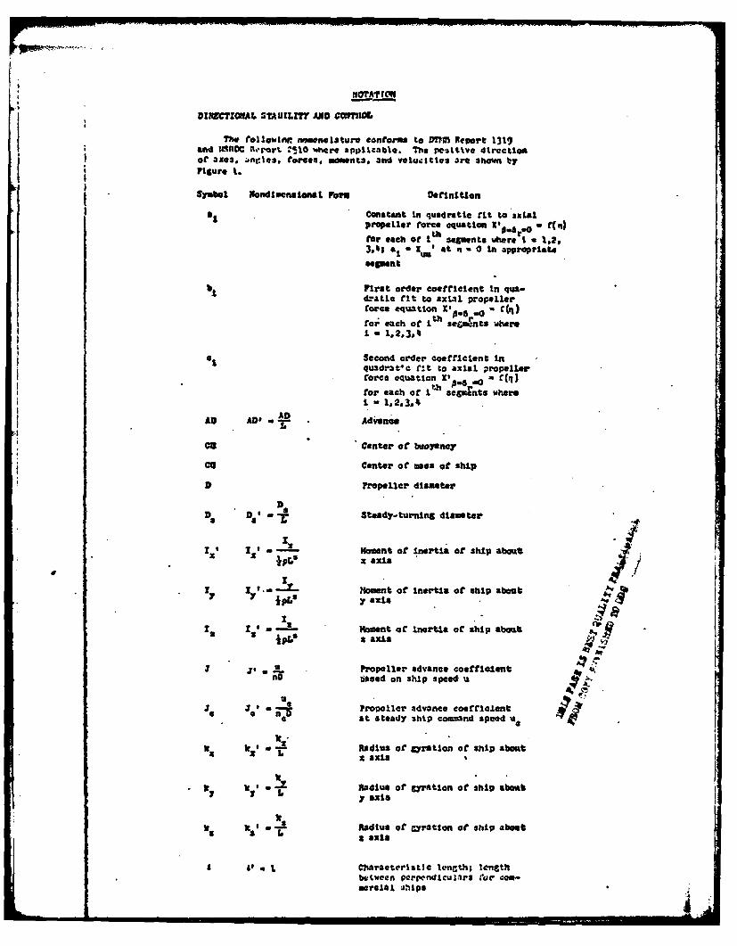
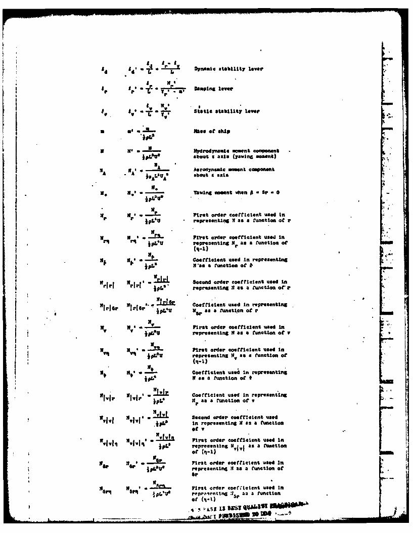
LOTAW
DIRECTZOIAL STAUZLZT AND M0flIM
The t@oil~nomenclature conforms to DTm Report 1319)and IMROC RI'rt T-10 Where applicable. The pos~itive direction
Figure 1.
Symbol Ifandlocnaional Foiw Definition
2 ~Constant in quadratic fit to axialpropeller force equation XO~ f (")for each of I segments wher: Wi u 1,2,
3,41en &1a Cu t n~ u 0i appropriate
b First order coefficient in qua--atle fit to axial propeller
force equation XIP*8 -0 , - q
foi each of Ith sefimrnts, whre
I.. - 1.1,
a t Soewalaeaeauocond order o Ieficent in
quadrat rle fct t o axialforce equation X -= " (
for ~ t each ofofor each air I segints MvereI - 1,2,3*4
AD AD' - A Adiann-I
U" " Center of buoyeano
cc Center of ma of ship
U Propeller dameter
t - Steady-turnlng diameter
I'sito- Moment of inertia of ship about:x' x' .pr.Sx axle
S M.?oment of Inertia of ship about7 Y PV y axis
I '~~LMoment of Inertia of ship about
S j, uPropeller advance coeffiicentnD bsed on ship speed. '
Je . - Propeller advance coefficienta nD at steady ship command speed e
Z y' - -" Radius of gyration of ship about% k 1 6 ,,x axis
k Radius or gyration of ship about
!s I !' - Radius of Cyrataon of ship about
A 1' * 1 Charaeteristic letieth; lengthbutween Verpndiculirs Car Ccm-aerelal UhIpaI
A4 a nm Dyamic albillty lover
A. A Damping laver
v .vIf N,' Sfatr stability lever
a as mes of ship
X mqe H ydr r Sdnaue moment coamponent
W s -LU5 sou - axis (yawlnG moment)"A NA Aerodynamic A oment comont
A • NAO * Aabout 9 axis
3.
* N. N3- Yawing moment when I Or O
pro First order coe ticient used inWr N jpL'3 representing N as a function ot r
W 3 * Prlt order coefricient used InInh rq IPL'U - representing Nr as a function ot
0 (q-i)
, * i b'coefficl.nt used In representing
N *asa f•untion of
Mrjrj %~I' s .. Second order coefficient used In_r jpf s " representing Hi as a .unctlon ora.
Nt!. 1g ~. Coefricient used In representlngirier ror as a function of r
II $, iff -IP- First order coefficient used In* representing N as a function of
n" N '- First order coefficient used is
ipev representing W. as a Function or
St we's Coefficient used In representin
*IVi N asea function o
Ivir- Coefficient used In representing
Not .I! I Second order coefficient used,1 XllI jp. In representing H as a function
of v
S First order coeffic'Lent used In- 1104' jpL' representing U.1 a a untionof (4-1)
pe "Or -oFirst order coefficient used inW ~ If.'U'representing it as a function of
Or
N N O, First order coeatlfent used In, pL'J reprotenting 3r a3 a function
of (q.1) 3-
!k_ zU., j~ S "
n P'ropeller revolution ra.te
ne Propeller revolution rate atretcady cooind i. cJ
% Ordered proplllor revolution rate
a, -, . Overehoot width oi path
0 Overshoot heading angle; measuredfrom value at second execute
* N' - Steady-turning radius; mL
Fr*" rt, 0 Angular velocity component about.
U a axis relative to fluid1L'% Angular acceleration cooponent
Us about a axis relative to fluid
T TO@ Tactical diameter
IllG- I ransfr"
to aTimtl tiee YLL
t1 ' - Tim at Ith execute In an over-shoot or :,gzag maneuver
tt _0-~ Time at Initiation of a maneuver
90r of heading in a turn lf
StlO t10 "Time to reach 180-degree change
18O 1 1 of heading In a turn -
• Lnear velocity oi origin ofbody &aes relative to fluid
' ,Component 6C V In direction of
direetion the z axis
a Command speed; steady value of4U ahead speed component u for agiven propeller rpm Cor P - Or - Osign changes with propeller re-versal
c Linear velocity of current
Ue Component of cc In direction of x axis
Linear velocity of origin or bodyaxis relative to fluid
tin Component orf 11 in direction of x axis
11 PVelocity at rudder due to motionand propeller race
UA Vind velocity

V* Component ot U4 In direction of y axs
comwonent of UR 1.1 direction of y axis
" Absolute speed i1 knote
I Steady approach speed In Itnota
V9 Speed in knots at 90-dereeheading chane In a tarn
Viso Speed In kots at 180-decreeheading 41Ai ie in a twusi
V vo .1 Compoent of V In direction otthe y axis
. 1Time rate o change st v tndirection of the y axle, tLongitud.Inal body axlm; also,"the coor-11nato PC a pIlnt rela-'' "
tive to the origin of body axes
x~S -- The x coordinate ofr CB
I *%. - - Tho x coordinate or Co
K K---.---: :,capoe-A A ~ A
• ' f Aerodynamic aore componen along
it zoo , A ,coot, lmr to oft"he dlzplmce~mcot"
of CO relative to the origin ofa set o." fixed axes i
Xy - ]Ry)drodyname force conponent "
*peg, ' along x axis (longitudinal. orazaL. ore)3
,eI X -r " Second order co tlcelat usedI in representing I as a functionof r. Firat order cocLienPt."
Is ZoreZ- -X4 Coefficient used In representing
i. X as a function or Oa
a -W Second order coefficient used*p~a in repretentIng X as a function
at u in the non-p-opelled case.First order coerficient Is zero
Z Coefficient used In representing" ' X1X a8 a anotion of the product
Yr
I,, I' . Second order coefficient usedTV in rspr,.Sent ng X as a functionoa v. First order coefficient A
Is cer-
• ,- First order coefficient usedTV L In representing XW as a Cunction *
of (q-1)
r X Second order coeftcient usedP }pL'IJ' In represent mg X 3s a (unction
of sr at I * 0. First orderc',efflclont Is toeo<:-2rr~lt~lt; lllr
r-- . Second order coetflcient usedbpfU4 in representuin Xgrr as a
flunotion of tk
y * - lateral body axis also the co-
Li ordinate of a point relative to
the origin of body axes
73The T co dinate of C1
r e' 'The y coordinate of Ca
76Sys A coordinate Of the displacement
or CG relative to the oriin of aset of fixed axes
YY* -- - Hydrodynsate force cooponent alongWs y ax±s (lateral force)
YA•
Aerodynamic force component along
TpA- UAa Y &ixL
o. ye La tra I force when - - 0
Distance at port pcopeller fromP cent. ruLne
T DistAnce ot starboard propeller two.a center1JAt.
T ' First order coefficient used in.j Y pL" representing Y as a function of r
TIM- .oe% First order coaciclent used inr*. jprepresenting Tr as a function of'
r .* ( saq-uI) to t" "*7r
T T I - Coet"iclet used In representingSIre as a. function of
l* r Second order coefficient it
win Y rI U representing T As a function of r
S-- 'irat order coeficcient used niTv, 1 V Jrepresenting Y as a function of T
Y First order coefficient used InTq vq x'U representing as a function of
l- Coefficient used In representlngjpL5 Y as a function of t
'win Tj J I-.k Coefficient used In representingY as a runction o r
T cfvi Tlvje Second order coefficient used ",iI)pL ropre~entnZ Yf 3s 3 Cunctlon o V
Yv v.'q vsoi First order coeCrcictnt used in
or (R)-7
Ta a. 1oe representing4 Y as a f'uncrtion of 5P .
, ,First order coerflcient used InTom arn J'Q representing Va as a tunctlon of G
lAngle at drift
Anale Of dritt relative to fluid
p P Deflection of flankJng rudder,
63 Deflection ot steering rudder
th5a Steady rudder angle at I executaIn an overshoot or :igzag maneuver;I - 1,2,3 .. .
6FLF- _' Flan"ing rudder deflection rate
a _ __ Steering rudder deflection rate
Ship propulsion ratlol "
elh~~ Toh " lhe ots of eharaeterlst2o sta-reasu 1 "edq- n r e r horzontal,plant tons I I,. o. 2
Rcadlnt or yaw anileIt|Reading angle, at I t h exece In
On overhoot or zigzag mineuver,
e,,ale from spiral maneuver
execute in an overshoot or zigzagmaneuve-' I. 2I3.
' .- Frequency of oscillation
iWo

HYDRONAUTICS, .Incorporated
1.0 INTRODUCTION
The towboat manuevering simulator is based on the integration
in time of the differential equations which describe the motions
of the towboat and barge string in three degrees of freedom, i.e.,
yaw, sway and surge. The theoretical background for these equations
are presented in Reference 1, "The Prediction of River Tow Maneu-
vering Performance," U.S. Coast Guard Report No. CG-D-32-78. This
reference presents the basic equations and a complete set of hydro-
dynamic coefficients for a representative towboat and barge train.
These coefficients were obtained by model tests.
This section of the simulator documentation provides a des-
dription of the basic equations of motion included in the simulator
and the relationships used to determine .external forces and moments
due to a bow thruster and wind. These equations are completely
general in nature and could be used, with the proper hydrodynamic
coefficients, to describe the maneuvering of vessels other than
towboats.
HYDRONAUTICS, Incorporated
-2-
2.0 MATHEMATICAL MODEL
The mathematical model for the maneuvering of a river towconsists of the coupled differential equations in three degreesof freedom (yaw, sway and surge) which describe the motions in
the X, Y plane and the complete set of hydrodynamic coefficientsand external forces which are required in order to numerically
integrate these equations. There are also auxiliary equationswhich describe the response of the steering and propulsion sys-
tem to external inputs.
A complete set of three coupled differential equations withall of the terms necessary to simulate normal maneuvers of sur-face ships are presented in Reference 2. These equations have
been used by HYDRONAUTICS, Incorporated to calculate the maneuver
trajectories for a wide range of surface ship types in deep andshallow water. These equations are based on a more complete setof equations developed by the U.S. Navy for the simulation of
submarine motions in six degrees of freedom. The equations inReference 2 differ from other sets of equations, such as those
of Reference 3 used to describe surface ship maneuvers pri-
marily in the way higher order terms are introduced. The equa-tions of Reference 3 use a Taylor expansion which results inodd functions being represented by linear and cubic terms. The
equations of Reference 2 are a square absolute representation forhigher order terms so that odd functions are represented by
linear and square terms. At large drift angles, which is a likelyoperating condition for a river tow, the forces and moments aredominated by cross flow drag which is proportional to velocity
squared. Thus, it is better to use equations in which forces andmoments are proportional to velocity squared rather than cubed.
As a result , the equations presented in Reference 2 were selected
------
HYDRONAUTICS, Incorporated
to form the basis for the equations which describe the maneuvering
of a river tow. There are a number of modifications which must
be made to these equations. These modifications and the resulting
set of equations are described in the following paragraphs.
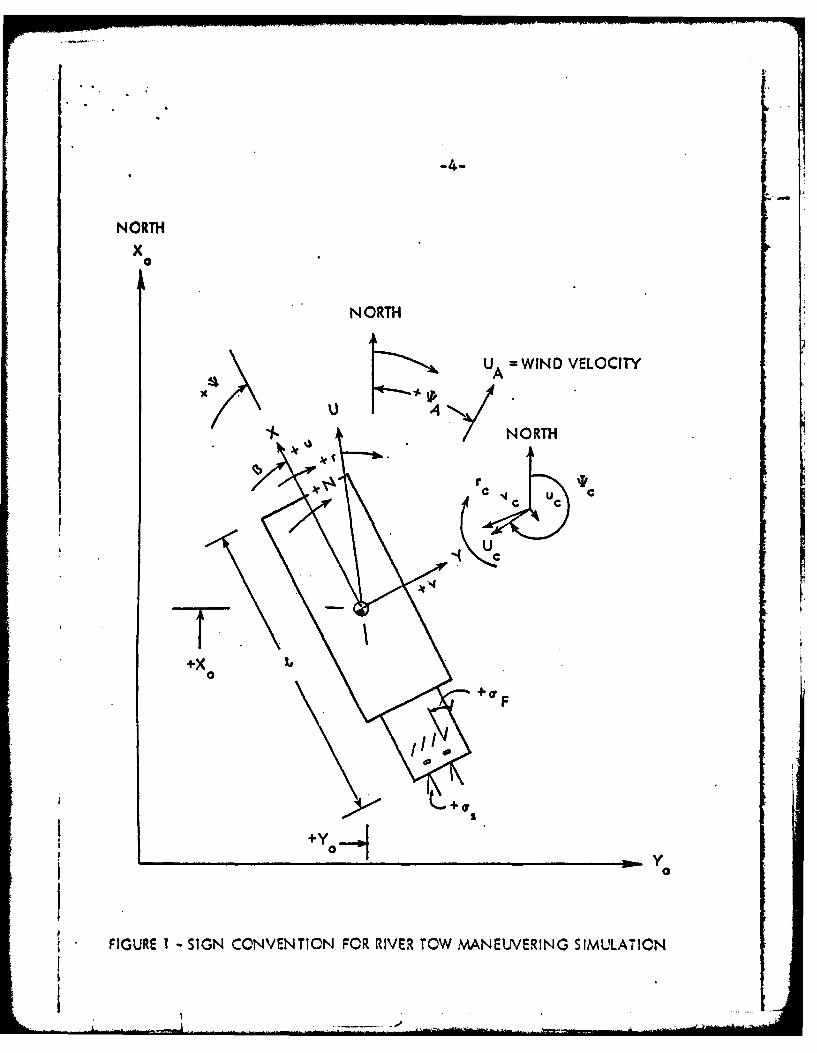
The following equations in three degrees of freedom are re-
ferred to a right-hand prthogonal system of moving axes, fixed inthe body, with its origin normally located at the center of massof the body. The positive direction of the axes, angles, linear
velocity components, angular velocity components, forces and moments
are given in Figure 1. Unless otherwise indicated in the Notation,
the numerical values for the hydrodynamic coefficients used withthe equations are for the ship propulsion point (n - 1.0). The
equations are written in terms of the complete barge flotillia
towboat configuration. Thus the values of the coefficients embrace
the interaction effects between rudder and hull, propeller and hull,and propeller and rudder as. determined from the model tests of the
complete configuration.
An important consideration in the maneuvering of a river tow
is the effect of current which can vary significantly along thelength of the tow. As a result, it is necessary to introduce the
effect of the current velocity into the mathematical model. Theapproach adopted was to define the hydrodynamic terms in the equa-
tions based on the relative velocities and yaw rate between the
hull and the fluid rather than the inertial velocities and yaw
rate. The relative velocities and relative yaw rate can be cal-
culated by the vector addition of the inertial velocity and iner-tial yaw rate and the current velocities and current yaw rate. In
the numerical integration the procedure is to define a matrix
of current speeds (U Cj) and directions (Tcjj) at points on the
X, Y plane. Based on the location of the bow (X B, Y.) midships
... ------.
-4-
NORTH
x0
NORTH
UA WIND VELOCITY
"/- NO0RTH
Ar rc 7 c
+X
oS
+ F
J,; +Yo
FIGURE I " SIGN CONVENTION FOR RIVER TOW MANEUVERING SIMULATION
_______
HYDRONAUTICS, Incorporated
-5-
(Xa, Y.) and stern (X , , Y,) of the tow, an interpolation in the
current speed and direction matrix is carried out to obtain thecurrent speed and direction at the bow (UCB, *CB) , midships
(UCM, *CM) and stern (Ucs, *CS). The following relationships then
apply:
UCE - UCB Cos (*Cs-) VCB M UCB sin (*CB-*)
uM M U cos (* U sin (U C5 CB ' Vs UCH sinuCS W-UCS Cos (*CS-*) vCS M-UCS sin (OCS-€
U UCB + uCM+ UCS vCB + VCM + vCS=C v " C (1)
V -vrcM CB - CS
UR = U-UC V1 R V-VC r - r-rC
In this procedure the mean longitudinal and lateral current velo-
city in the body axis system is obtained from the average of the
values at the bow, midships and stern. The variation of the
lateral velocity along the tow is accounted for by the apparent
current yaw rate defined by the difference in the lateral velo-
cities at the bow and stern divided by length. This assumes the
lateral velocity varies linearly from bow to stern. If this isnot the case a more complex relationship would have to be intro-
duced.
The equations of motion formulated for a river tow are as
follows:
HYDRONAUTICS, Incorporated
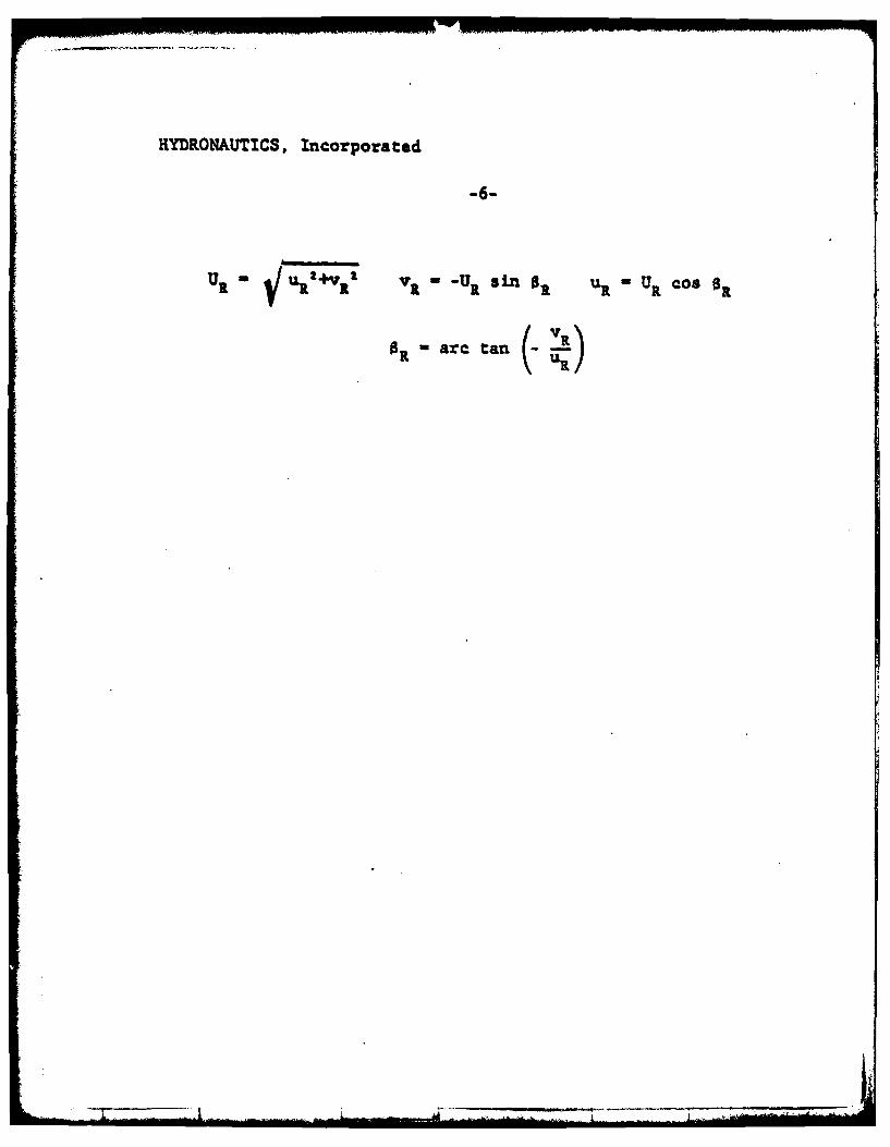
U1 ~ l1 R v - UR 'sn OR U UR Cog OR
OR are tan (- a

-7-
C4
as
40
'0
+ wm
'0
++ '.
0.qdo
y4L.. -.
0N
w >
+++
+ o+
> >
+ +

0 44
+4-
w - - - -
040
4 c 94+ 4 - +
CA 1 - O
> 96
.4 4. 4r~~~a at404b-14 - I.

4 0IC
*966
0) 0
C4 k
01C4 +~ +
+~-%It
- ~o + FO 44 + -
$44 =10 +-a -3
d
> +0
4p ~at at C
at at 0
+1' + -
A. - M
HYDRONAUTICS, Incorporated
-10-
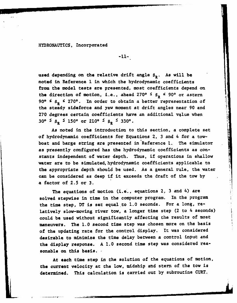
The foregoing equations of motion, as noted previously, are pat-
terned after the quasi-steady state equations of Reference 2. The
non-dimensional hydrodynamic coefficients which comprise the basic
equations are considered to be independent of speed (Froude number).
This assumption is valid since river tows always operate at low
Froude number.
These equations differ from the equations of Reference 2 in
the following details:
a. They are written in terms of the relative velocities
and yaw rate to allow the introduction of varying current as
discussed above.
b. Terms are included for steering rudders (steering rudder
angle - S.) and flanking rudder (flanking rudder angle - 8).
c. Terms are included for twin propellers which nay operate
at different RPM's and different directions of rotation. The
turning moment due to differential thrust is included in the yawing
moment, Equation (4).
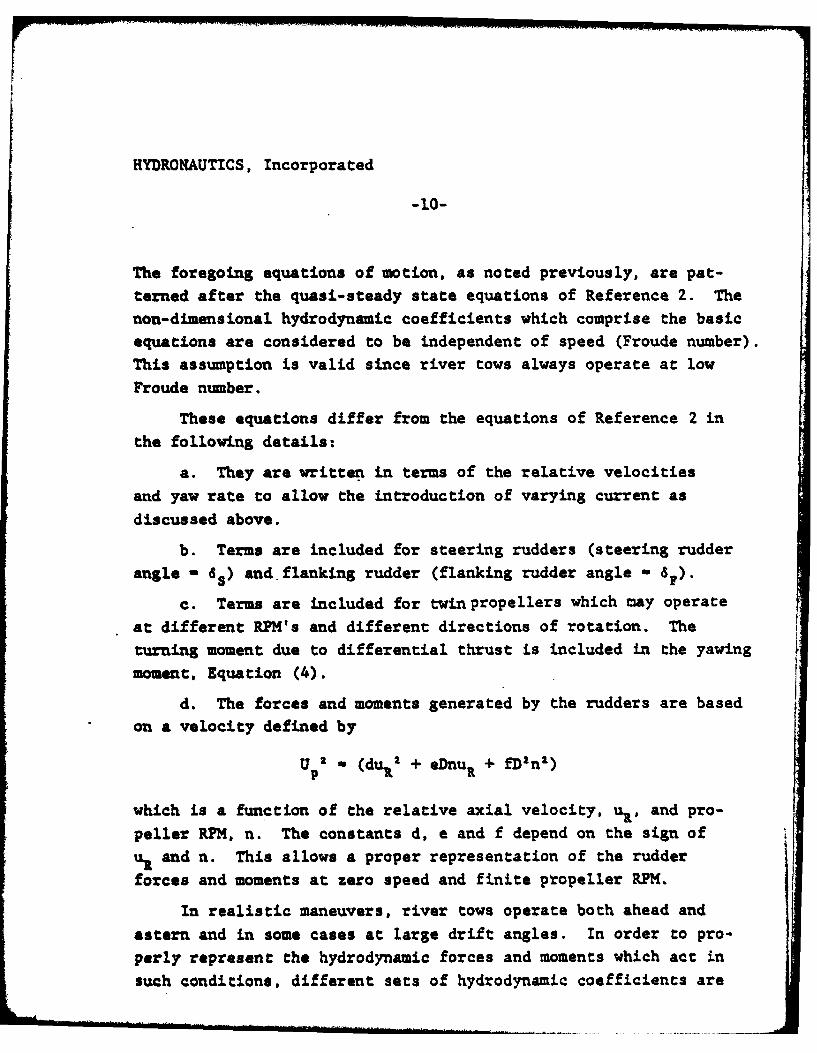
d. The forces and moments generated by the rudders are basedon a velocity defined by
Up -f (dulf2 + eDnuR + fD'n)
which is a function of the relative axial velocity, uR, and pro-
peller RPM. n. The constants d, e and f depend on the sign of
ut and n. This allows a proper representation of the rudder
forces and moments at zero speed and finite ptopeller RPM.
In realistic maneuvers, river tows operate both ahead and
astern and in some cases at large drift angles. In order to pro-
perly represent the hydrodynamic forces and moments which act in
such conditions, different sets of hydrodynamic coefficients are
HYDRONAUTICS, Incorporated
-11-
used depending on the relative drift angle 0 . As will be
noted in Reference 1 in which the hydrodynamic coefficients
from the model tests are presented, most coefficients depend on
the direction of motion, i.e., ahead 2700 R 900 or astern
900 OR 1 2700. In order to obtain a better representation of
the steady sideforce and yaw moment at drift angles near 90 and
270 degrees certain coefficients have an additional v4lue when
300 < 0 S 1500 or 2100 S R S 3300.
As noted in the introduction to this section, a complete setof hydrodynamic coefficients for Equations 2, 3 and 4 for a tow-
boat and barge string are presented in Reference i. The simulator
as presently configured has the hydrodynamic coefficients as con-
stants independent of water depth. Thus, if operations in shallow
water are to be simulated, hydrodynamic coefficients applicable to
the appropriate depth should be used. As a general rule, the water
can be considered as deep if it exceeds the draft of the tow by
a factor of 2.5 or 3.
The equations of motion (i.e., equations 2, 3 and 4) are
solved stepwise in time in the computer program. In the program
the time step, DT is set equal to 1.0 seconds. For a long, re-
latively slow-moving river tow, a longer time step (2 to 4 seconds)
could be used without significantly affecting the results of most
maneuvers. The 1.0 second time step was chosen more on the basis
of the updating rate for the control display. It was considered
desirable to minimize the time delay between a control input and
the display response. A 1.0 second time step was considered rea-
sonable on this basis.
At each time step in the solution of the equations of motion,
the current velocity at the low, midship and stern of the tow is
determined. This calculation is carried out by subroutine CURT.
HYDRONAUTICS, Incorporated
-12-
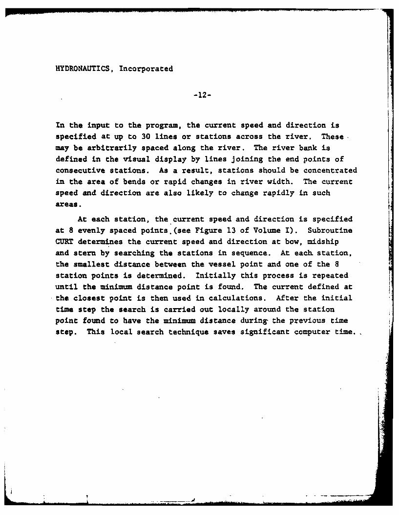
In the input to the program, the current speed and direction is
specified at up to 30 lines or stations across the river. These-
may be arbitrarily spaced along the river. The river bank is
defined in the visual display by lines joining the end points of
consecutive stations. As a result, stations should be concentrated
in the area of bends or rapid changes in river width. The current
speed and direction are also likely to change rapidly in such
areas.
At each station, the current speed and direction is specified
at 8 evenly spaced points.(see Figure 13 of Volume I). Subroutine
CURT determines the current speed and direction at bow, midship
and stern by searching the stations in sequence. At each station,
the smallest distance between the vessel point and one of the 8
station points is determined. Initially this process is repeated
until the minimum distance point is found. The current defined atthe closest point is then used in calculations. After the initial
time step the search is carried out locally around the station
point found to have the minimum distance during the previous time
step. This local search technique saves significant computer time..
HYDRONAUTICS, Incorporated
-13-
3.0 EXTERNAL FORCES
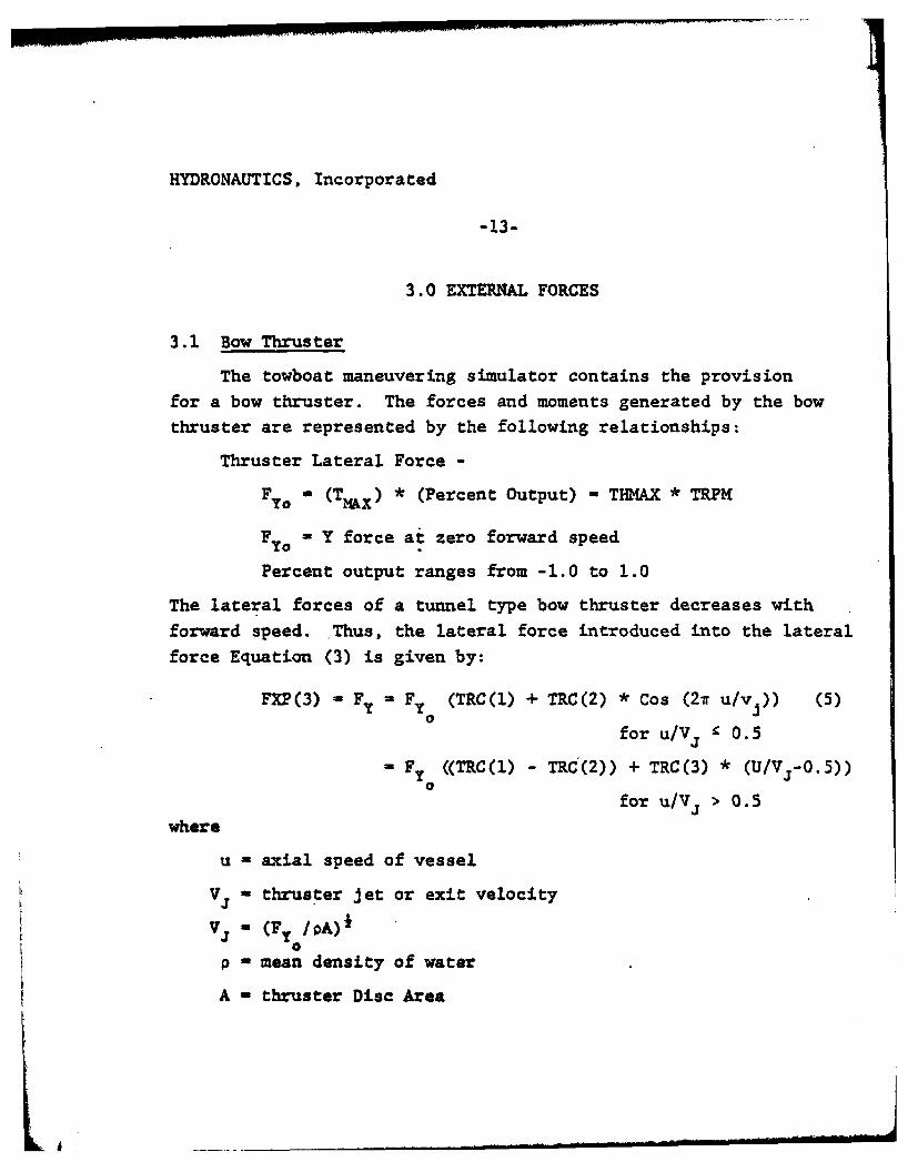
3.1 Bow Thruster
The towboat maneuvering simulator contains the provisionfor a bow thruster. The forces and moments generated by the bowthruster are represented by the following relationships:
Thruster Lateral Force -
FYo - (TMAx) * (Percent Output) - THMAX * TRPM
FYO - Y force at zero forward speed
Percent output ranges from -1.0 to 1.0
The lateral forces of a tunnel type bow thruster decreases with
forward speed. Thus, the lateral force introduced into the lateral
force Equation (3) is given by:
FXP(3) - Fy - Fy (TRC(l) + TRC(2) * Cos (27 u/vj)) (5)0
for u/Vs f 0.5
- Fy ((TRC(l) - TRC(2)) + TRC(3) * (U/Vj-0.5))
for u/Vj > 0.5where
u - axial speed of vessel
Vj - thruster jet or exit velocity
vi - (F /pA)f0
p - mean density of water
A - thruster Disc Area
HYDRONAUTICS, Incorporated
-14-
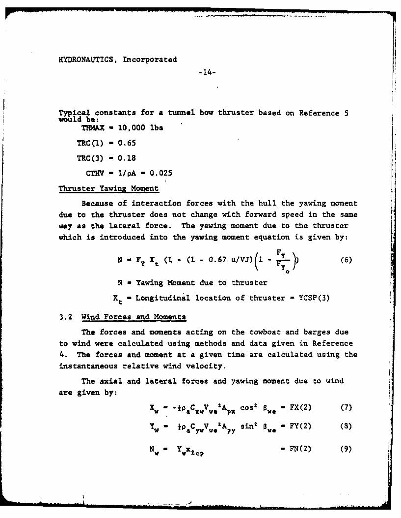
Typical constants for a tunnel bow thruster based on Reference 5would be:
THKAX - 10,000 lbs
TRC(l) - 0.65
TRC(3) - 0.18
CTHV - I/PA - 0.025
Thruster YawinR Moment
Because of interaction forces with the hull the yawing momentdue to the thruster does not change with forward speed in the sameway as the lateral force. The yawing moment due to the thrusterwhich is introduced into the yawing moment equation is given by:
N Fy Xt (1 - (1 - 0.67 u/VJ)(1 -1 7) (6)YO
N - Yawing Moment due to thruster
Xt - Longitudinal location of thruster - YCSP(3)
3.2 Wind Forces and Moments
The forces and moments acting on the towboat and barges due
to wind were calculated using methods and data given in Reference
4. The forces and moment at a given time are calculated using the
instantaneous relative wind velocity.
The axial and lateral forces and yawing moment due to wind
are given by:
Xw -*PaCcvV. 2A cos 2 we -FX(2) (7)
Yw " 0aCy VG 'Ap sin2 S = FY(2) (8)
N- YWx1CP - FN(2) (9)
... .......... ... , , . _ ... .. l
VHYDRONAUTICS, Incorporated
-15-
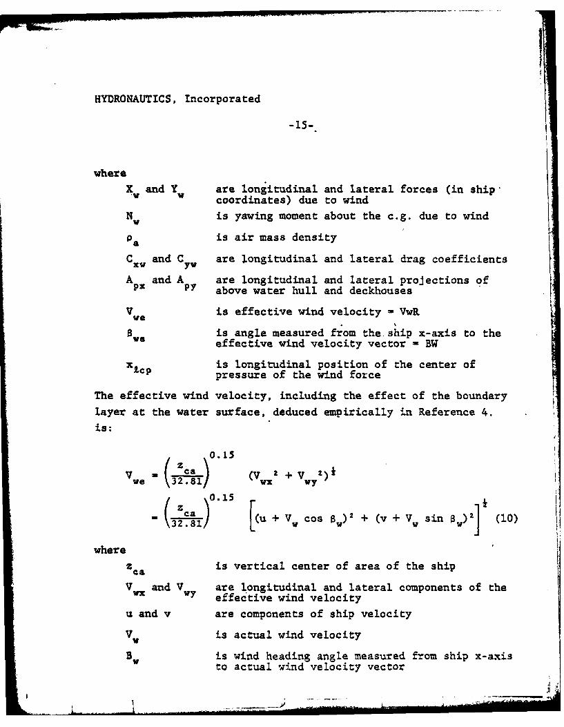
X and Y are longitudinal and lateral forces (in ship-V coordinates) due to wind
Nw Vis yawing moment about the c.g. due to wind
Pa is air mass density
C x and C are longitudinal and lateral drag coefficients
A and A are longitudinal and lateral projections ofx P above water hull and deckhouses
V Ve is effective wind velocity = VwR
is angle measured from the ship x-axis to theeffective wind velocity vector - BW
is longitudinal position of the center ofX£CP pressure of the wind force
The effective wind velocity, including the effect of the boundarylayer at the water surface, deduced empirically in Reference 4.
is:
0.15Z ca (V )2+ v
ve \32V1 WX W7
SICa .1 u +V cos ) + (v + V sin 8w)J (10)
wherez ca is vertical center of area of the ship
V Vand V are longitudinal and lateral components of theVi Wn V effective wind velocity
u and v are components of ship velocity
V V is actual wind velocity
Bw is wind heading angle measured from ship x-axisto actual wind velocity vector
HYDRONAUTICS, Incorporated
-16-
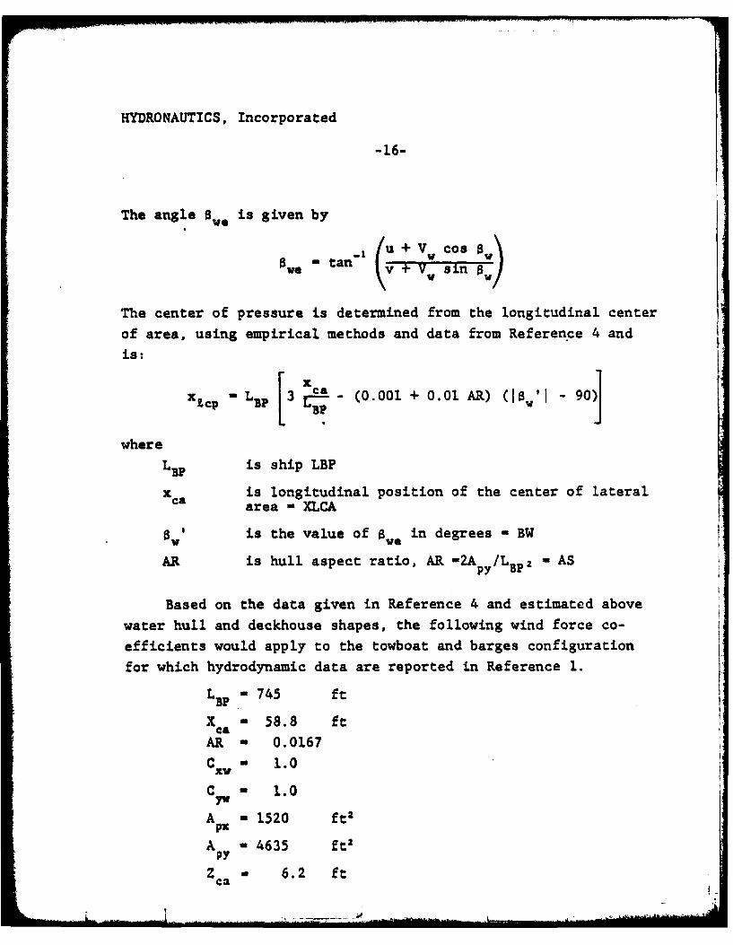
The angle BW, is given by
ova -tan V sin
The center of pressure is determined from the longitudinal center
of area, using empirical methods and data from Reference 4 and
is: xx - L1 p 3 ± - (0.001 + 0.01 AR) (IS,'I - 90
where
L BP is ship LBP
x is longitudinal position of the center of lateralca area - XLCA
aw is the value of awe in degrees - BW
AR is hull aspect ratio, AR -2Ap /LBp - AS
Based on the data given in Reference 4 and estimated above
water hull and deckhouse shapes, the following wind force co-
efficients would apply to the towboat and barges configuration
for which hydrodynamic data are reported in Reference 1.
L BP- 745 ft
X - 58.8 ft
AR - 0.0167
C W 1.0xv
C W 1.0
A - 1520 ft2
A - 4635 ft,
ZCa a 6.2 ft
HYDRONAUTICS, Incorporated
-17-
3.3 Other External Forces
At this time no other external forces are included in the
simulator. In the future, othe. external forces such as bank
suction, interaction with passing vessels and the effects of moor-
ing lines could be included.
-I:
HYDRONAUTICS, Incorporated
-18-.
4.0 CONTROL SYSTEMS
The coatrol systems included in the towboat maneuvering
simulator include steering control for the steering and flanking
rudders, RPM control for the port and starboard propellers and thebow thruster output control. The command inputs for all of these
controls are provided thru the computer A to D input from the con-
trol station. In the simulator, the response to the control inputs
is at a constant rate. The rates used based on Reference 6 are
as follows:
Steering and Flanking Rudderd 5 deg/sec
Propeller RPM 20 RPM/sec
Thruster Output 10 percent thrust change/sec
The response to the control system inputs is considered re-presentative of a typical towboat. If required in the future, amore complex representation of the response to control inputs couldbe modeled in the simulator.
HYDRONAUTICS, Incorporated
. -19-
REFERENCES
1. Miller, E.R., Jr., "The Prediction of River Tow ManeuveringPerformance", U.S. Coast Guard Report No. CG-D-32-78, May1978.
2. Goodman, Alex, Gertler, Morton, and Kohl, Robert, "Experi-mental Techniques and Methods of Analysis Used at HYDRONAUTICSfor Surface Ship Maneuvering Predictions", HYDRONAUTICS,Incorporated Technical Report 7600-1, June 1976.
3. Mandel, P., "Ship Maneuvering and Control", Principles ofNaval Architecture, Chapter VIII, SNAME, 1967.
4. Altman, R., "Forces on Ships Moored in Protected Waters",HYDRONAUTICS, Incorporated Technidal Report 7096-1, July1971.
5. Chislett, M.S., and Bjorhkorn, 0., "Influence of Ship Speedon the Effectiveness of Lateral-Thrust Unit", Report No.HY-8; HYA, Lyngby, Denmark, April 1900.
6. Courtsal, D.P., "The Marine Business in the Central UnitedStates", Transactions SNAME, Vol. 79, 1971, pp. 542-578.
t-I

![LCD-78-334 General Services Administration Should Do More ...DOGOHENT BESOHE 07331 - £826117702] Geaeral Services Adiinlstxatioit Shoold Do Aore Te Avoid ?oaiidation Constructioji](https://img.pdfslide.us/doc/110x75/5fbc43a1161f5c105a244583/lcd-78-334-general-services-administration-should-do-more-dogohent-besohe-07331.jpg)
![Service Manual [ Team AoRE ]¡rio-2016-2-Cartaz-dos... · Service Manual [ Team AoRE ] Horário criado:19/09/2016 aSc TimeTables IIN2014 Programação OO IIN2016 Fundamentos de Informática](https://img.pdfslide.us/doc/110x75/5e2a52ad6b0a7c0512611e96/service-manual-team-aore-rio-2016-2-cartaz-dos-service-manual-team-aore.jpg)