Embed Size (px)
Citation preview

AD-AII5 680 ARMY ENGINEER DISTRICT LOUISVILLE KY F/S 13/2SOUTHWESTERN JEFFERSON COUNTY, KENTUCKY. LOCAL FLOOD PROTECTION--ETC(U)APR 82
UNCLASSIFIED NL
EEELH6L 82

UniclazaifiedSCURITY CLASSIFICATION OF THIS PAGE (USben Date Entoe0 717
REPORT DOCUMENTATION PAGEBEOECMETGFR
[E O R M MU R i. GON CC ESION he S. RE PI V 1CATALOG NUMBER
4. TITLE (and Subtitle) S. TYPE OF REPORT & PERIOD COVERED1
iSWp16wnrt No. 5: Southwestern Jefferson County, Foundation ReportKentucky-Local flood protection project. 6 EFRIGOG EOTNME
7. AUHOR~s S. PECORAING ORG.REPT NUMBER
7. AUTNORWa)
9. PERFORMING ORGANIZATION NAME AND ADDRESS 10. PROGRAM ELEM64 NT, PROJECT, TASK
USAE Louisville
CONTROLLING OFFICE NAME AND ADDRESS 12. REPORT DATEAril 1982
ISME (CD-I) Louisville is. NUMBER OF PAGES
_________________________________ 12p 10plans, 22 1.__photosOMoNfTORING AGENCY NAME & ADORESS(I different from Conrolling Office) 1S. SECURITY CLASS. (of tis report)
Unclassified
Irs.a. DECL ASS# FICATION/ DOWN GRADI NGSCHEDULE
SDISTRIBUTION STATEMENT (of this Report)
~ pproved for public release; distribution unlimited.
D4STRIBUTION STATEMENT (of the abstract entered In Block 20, It different frogn Report)
SUPPLEMENTARY NOTES
Construction pumping stations: Riverport pumping station; Lower Mill Creekpumping station; Upper Mill Creek pumping station.
19. KEY WORDS (Continue on reverse aide Iftnacosaay end Identlify by block number)
Jefferson County, Kentucky Upper Mill Creek/Riverport Pumping Station ExcavationsiLower Mill Creek Sub-surface drainage
>lood Protetion
AnaTRACT (Ceuie s eme i e eseaw ad identity by block numaiber)
C-" Aesults,~f inspections at three pumping station construction sites inSouthwestern Jefferson County, Kentucky.
VD"'"" 3 menoww i0 move ~is ossoLir Uncassfie
SECURITY CLASM FICIATIOR OF THIS PACE (When Dae t ntered)
DISCLAIMER NOTICE
THIS DOCUMENT IS BEST QUALITYPRACTICABLE. THE COPY FURNISHEDTO DTIC CONTAINED A SIGNIFICANTNUMBER OF PAGES WHICH DO NOTREPRODUCE LEGIBLY.
/I
K x~i ___

FOUNDATION REPORT
SUPPLEMENT NO. 5
SOUTHWESTERN JEFFERSON COUNTY, KENTUCKY
LOCAL FLOOD PROTECTION PROJECT
CONTRACT NUMBERS
DACW2 7-79-C-Ol0o
DACW.27-81-C-0125
CON'STiRUCTION PUMPING STATIOlNS
Rivcerport PuiipinA SLation
Lower IMill Creek Pumping Station
Upper Mill Creek Pumping Station
I-n
April 1982 -
,y~~1
D710 -
-'" ...-COPY
INSrr. V
* *-~3
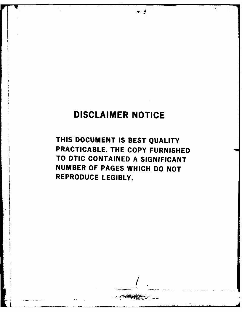
(.j TABLE OF CONTENTS
Subpara[traph Page
TEXT
Section 1 - INTRODUCTION
01 Location of Pumping Stations 1-1
02 Contractors 1-1
02a Riverport and Lower Mill Creek Pumping 1-1
Stations02b Upper Mill Creek Pumping Station 1-2
03 Contract Supervision 1-3
03a Riverport and Lower Mill Creek Pumping 1-3
Stations03b Upper Mill Creek Pumping Station
Section 2 - FOUNDATION EXPLORAT10NS
01 Subsurface Investigations Prior to 2-1Construction
Ola Riverport Pumping Station 2-1Olb Lower Mill Creek Pumping Station 2-1Olc Upper Mill Creek Pumping Station 2-I02 Subsurface Investigations During 2-2
Construction
Section 3 - GEOLOGY
01 Topography 3-102 Project Geology 3-1
Section 4 - EXCAVATION PROCEDURES FOR FOUNDATIONS
01 Method of Excavation 4-1
Ola Riverport Pumping Station 4-1Olb Lower Iill Creek Pumping Station 4-1
Olc Upper Mill Creek Pumping Station 4-I02 Deviations From Planned Conditions 4-2
" w - - - .

S Subparagraph Page
Section 5 - POSSIBLE FUTURE PROBLEMS
01 Conditions That Could Produce Problems 5-1
Ola Founding Conditions on Pumping Plants 5-1
FoundationOlb Upper Mill Creek Electric Substation 5-1
Foundation02 Recommended Observations 5-1
Plate Description
I Location of Pumping Stations
2 Site Plan of Riverport Pumping Station3 Site Plan of Lower Mill Creek Pumping Station
4 Site Plan of Upper Mill Creek Pumping Station
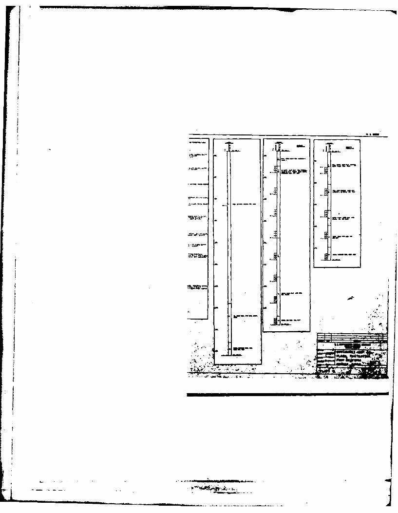
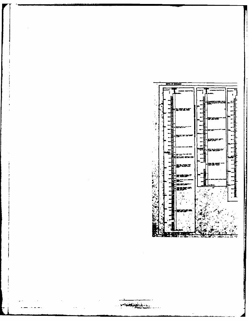
5 Boring Logs6 Boring Logs7 Dewatering Well Location8 Details of Dewatering Well and Excavation Plan
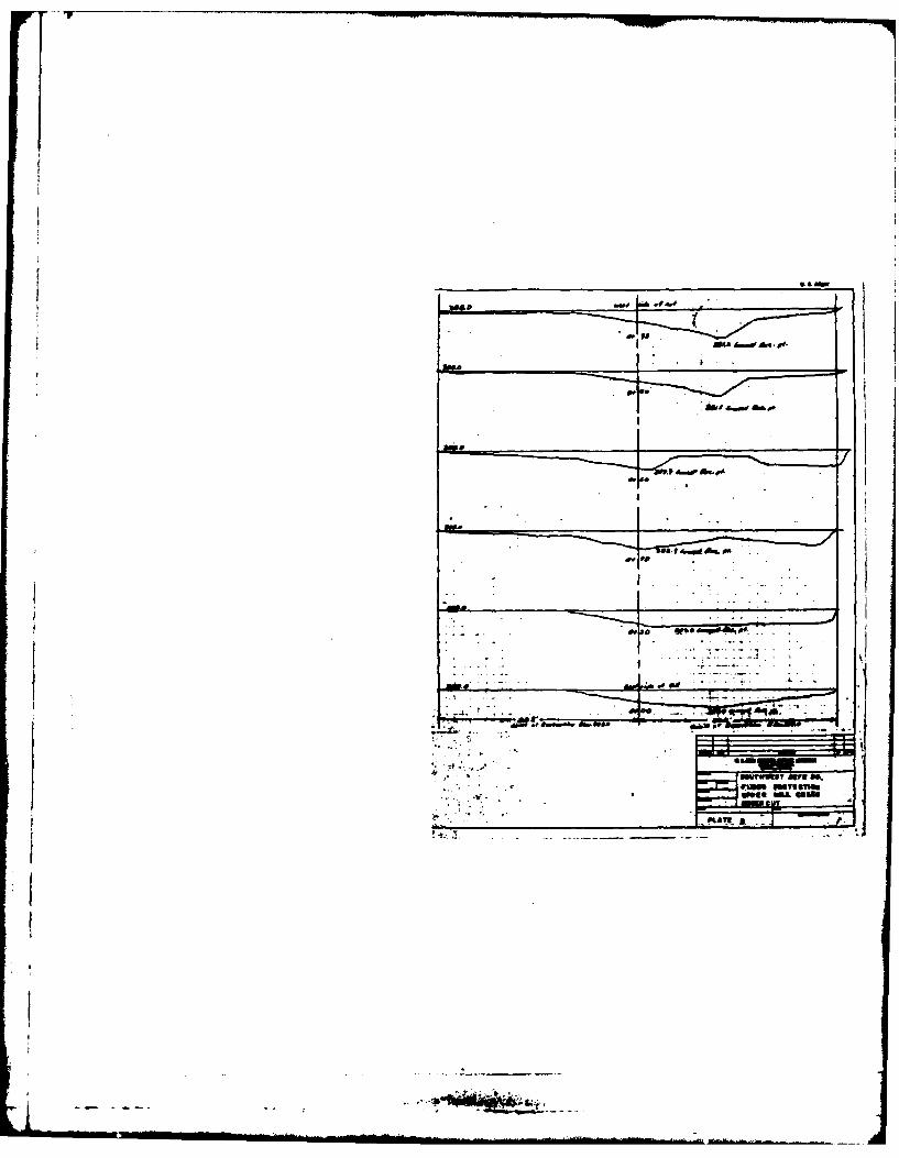
9 Undercut Details at Upper Mill Creek Pumping Station10 Foundation Drain
Piotos Volu;,ie I - Foundation 3t Riverport, Lower Mlill Creek
and Upper 'ill Creek Pumping Stations
C

I NIRODUCTION
1-01 Location of Pumping Stations. The pumping stations coveredin this supplement are identified and located as follows:
Name Levee Section Station
Riverport Section 1 433+45
Lower Mill Creek Section 2 695+85Upper Mill Creek Section 3 228+00
ocations of the pumping stations are shown on Plate Numbers 1, 2, 3 and 4.
The purpose of the pumping stations is to pump runoff from rainfall over thelevee from the landside or protected side to the riverside during floodconditions.
1-02 Contractors.
1-02a The prime contractor for construction of the Riverport andLower Mill Creek Pumping Stations was the E. H. Hughes Company ofJeffersonville, Indiana. Mr. Michael P. Murphy was the home officerepresentative directly responsible for the contract. Mr. Don Barrett wasthe superitendent responsible for all onsite operations throughout theduration of the contract. Tiie E. H. 1lughes Company did all concrete workon the pumping stations and installed the Government Furnished Property.Nine firms subcontracted to the prime contractor for various aspects ofthe construction as follows:
(1) Electric - Strange Electric Co.Louisville, Kentucky 40215
(2) Plumbing - Southern Plumbing & Piping, Inc.Louisville, Kentucky 40210
(3) Painting - Payne and Hager, Inc.Louisville, Kentucky 402024
(4) Roofing - Abram Roofing CompanyLouisville, Kentucky 40214
(5) Seeding & Sodding - Jacobi Sodding Service, Inc.Floyd Knobs, Indiana 47119
(6) Masonry - a and 8 Masonry Construction Co., Inc.New Albany, Indiana 47150
C ? -I

((7) Fence - Builders UnlimitedFairfield, Ohio 45014
(8) Reinforcing Steel - National Reinforcing SteelLouisville, Kentucky 40209
(9) Earthwork (Sitework) - Cundiff Construction Co., Inc.Louisville, Kentucky 40201
l-02b The prime contractor for construction of the Upper MillCreek Pumping Station was Batteast Construction Company of South Bend,Indiana. Mr. Eugene Staszewski was the home office representative directlyresponsible for the contract. Mr. Del Shanks was the superintendentresponsible for onsite operations. Batteast Construction Company performedthe concrete work on the pumping station. The following firms contractedto the prime contractor for various aspects of the construction:
(1) Site Dewatering - Kelley Contract Dewatering Co.Wyoming, Michigan 49508
(2) Earthwork - RAM Engineering & Construction, Inc.Louisville, Kentucky 40232
Chilton Engineering & Construction, Inc.Louisville, Kentucky 40218
(3) Reinforcing Steel - South Central ErectorsSouth Bend, Indiana 46617
(4) Guard Rail - Kentucky Guard Rail Company, Inc.
Elizabethtown, Kentucky 42701
(5) Electric - Henderson Electric Co., Inc.Louisville, Kentucky 40213
(6) Mechanical - drock Electric Company, Inc.
Clarksville, Indiana 47130
1-2
r*WA-4- -*!

1 -03 Contract Supervision.
a. Governm~ent personnel responsible for onsite administration
of work on iRiverport and Lower Ifill Creek Pumping Stations were:
(1) M~r. Kenneth Ladd - Resident Engineer(25 May 1979 through 19 October 1980)
(2) Mr. Gary V. Fitzgerald - Resident Engineer(20 October 1980 through Completion)
b. Government personnel responsible for onsite administrationof work on Upper '.,ill Creek Pu~mping Station was Mr. Gary V. Fitzgerald-Resident Engineer
1-3

FOUNDAT10A EXPLORAT1ONS
2-01 Subsurface Investigations Prior to Construction.
a. Riverport Station - The subsurface conditions wereinvestigated by drive sample, hand auger and undisturbed Denison tubesampling. Borings D-816 and UD-512 were drilled to determine the soilconditions in this area. Locationsof the borings are shown on PlateNumber 2. Logs of the borings are shown on Plate Number 5. Foundingelevation for the structure is 413. The to? of Boring UD-512 is elevation416.8; the bottom of the hole is elevation 366.8. Alluvial, silty to leanclays were encountered between elevations 416.8 and 395- overlying fine tocoarse grained sand of glacial ouLwash origin. The top of bedrock isapproximately elevation 327 + . Groundwater levels closely reflect OhioRiver stage levels at any particular time. Normal pool elevation is 383.An allowable bearing value of 3,000 pounds per square foot is assigned tothe sandy materials on which the structure is founded.
b. Lower Mill Creek Station - The subsurface conditionswere investiated by power auger. dorings 6, 0-1069 through 1072 andD-1541 were drilled to define the soil conditions at the structure site.Location of the borings are shown on Plate Number 3. Logs of tie boringsare shown on Plate Number 5. Boring i)-1070 was drilled in the locationof the pumping statiol,. kouiiing clevatioT of the structure is 408.5.Top of grouiid was 42(,.l and butto;n of hole was 336.1. Silty to sandyclay .as encountered overlying sailds and gravels at elevation 400.1.Water was encountered at elevatioti 390.1. An allowable bearing valueof 3,0U0 pounds per square foot is assigned to the founding material.
c. Upper Mill Creek Station - The subsurface conditionsat the pumping station were investigated by drive and undisturbedShelby tube sampling. Borings U-1019, D-1301 and S-1304 were drilled todetermine the soil conditions in the area. Location of the borings areshown on Plate Number 4. Logs of the borings are shown on Plate Number 5.Ground elevation is approximately 401- in the area of the borings. Fromtop of ground to 390- the borings indicated silty clay with trace of sand.Below elevation 39C4, the soil changes to clayey sands and gravel. Bedrockwas encountered at elevation 339± in Boring SDC-1017 which is locatedapproximately 120 feet from tie pump plant. Bedrock is the New Albany shalewhich is a moderately hard carbonaceous shale. Groundwater levels willclosely reflect Ohio River stage levels at any particular time. Normalpool for the Ohio River is 383 in this area. A bearing value of 4,000pounds per square foot had been assigned to the in situ silty clay aboveelevation 390-. It was originally intended that the pump station wouldbe founded at elevation 406.51 on the in situ silty clay. The preliminaryinvestigative data and preliminary design data are presented in DesignMemorandum Number 4. In May 1980 upon digging the inspection trench near
02-1
Station 229 - on Levee Section 3, a large quantity of waste fill was encountered.The waste material was cowposed of heterogeneous materials such as soil,brick, metal, concrete, etc., overlying earlier deposited black flyash.Engineerin6 Division, Geotechnical Branch performed subsequent borings todetermine the extent of the waste material. A representative sample ofthe bore logs are shown on Plate Number 6. Locations of the borings areshown on Plate Number 4. By Modification Number P00008 to ContractNumber UACW27-78-C-004b for construction of Levee Section 3, the wastematerial was removed from the foundation limits of the pumping station.During this subsurface exploration by Geotechnical Branch it becameapparent that tne proposed qump station, if constructed on in situmaterial at elevation 406.5-, would be founded on soft clay. A settlementanalysis indicated that if the station was constructed on this material,approximately six inches of settlement could be expected within nine toten months. A plan was developed to remove this soft material to elevation368 where in-siLu foundation sand would be encountered. The excavation wouldthen be backfilled with sand from the borrow area. The sand from theborrow area would be permitted to contain a maximum of 20 fines passingthe W2OO sieve. This plan was submitted by ORLEi-D to Division Engineer,Ohio River for consideration by letter dated 9 December 1980. By subsequentindorsements, concern was expressed by Ohio River Division's personnel thatthe refill sand, containing up to 20% fines, would not be as pervious asthe in place foundatioii sand and that the plant wold not withstand upliftforces under full flood stage. Ohio River Division's personnel recommendedthat positive pressure relief for the foundation be incorporated into thedes ign. At a meeting in the Louisville District Office on 29 June 1981between Louisville District Office's personnel and Ohio River DivisionOffice's personnel, a design was adopted for positive pressure reliefcomposed of lateral drains with the capacity for a maximum computed flowof (37- CFS), a three feet thick drainage blanket and outlet manholes thatpermit inspection of the drainage system. The foundation drain systemis shown on Plate Number 1U. On top of this drainage system which wasinstalled at elevation 388, refill sand from the borrow area would beplaced to elevation 406, the founding elevation of the pump plant slab.
2-02 Subsurface Investigations During Construction. Investigationsduring construction consisted of visual inspection after excavation to therequired lines and grades (see paragraph 4 -02a). The sand refill requiredto bring the excavation up to the founding elevation was subjected to bothQuality Assurance and Quality Control testing. Along with visual inspections,density and gradation tests were performed.
2-2

C GEOLOGY
3-01 Topography. The topography of Southwestern Jefferson Countyin the Ohiu River flood area is essentially flat to very slightly rolling.
Several terraces, ranging from 10 to 20 feet in height, have been developedduring adjustment of the Ohio River to its present channel following theend of the Pleistocene Epoch. Relief ranges from elevation 385 at water'sedge to about 435-. Locally, the terrain is broken by narrow tributaryvalleys entering the Ohio River such as Mill and Pond Creeks.
3-02 Project Geology. The project area is located in an areaof deep overburden material of glacial origin ranging from clays to sandygravels. For the most part, the overburden represents outwash depositsfollowing the Illinoian glacial retreat. Depth of the overburden rangesfrom 50 to IOu feet. Ten to 20 feet of recent alluvium overlies theglacial outwash deposits along the Ohio River bank and in the smalltributary valleys and consists primarily of clays, silts and locallyrestricted areas of gravelly sand. The outwash is primarily gravelly sandto sandy gravel overlain and interbedded with silts and clays at the higherelevations. Seepage will not be a problem at these sites because of thedepth of impervious cover. 6edrock consists of clay shale of the NewProvidence formation of Mississippian Age. bedrock relief along the axisof the project ranges from elevation 32b to about 340 except at the southend of the project where the levee ties into bedrock hills.
3-
~3-I
4-91 Methol uf Excavation.
a. Riverport - The contract plans and specifications
required the pumping station to be built essentially on existing material
after excavation to the required grade. The foundation was excavated to
the required grade using a tracked front end loader, tracked backhoe and
dump truck. The foundation material encountered was a silty clay that
provided a firm foundation. No overexcavation or undercut was required;
tile lean concrete mat was placed directly on the clay foundation at the
specified elevation.
b. Lower Mill Creek - The contract plans and specificativ.srequired the pumping station to be built essentially on existing materialafter excavation to the required grades. The foundation was excavated tothe required grades using a tracked front end loader, tracked backhoe anddump truck. The foundation material encountered was a lean clay thatprovided a firm foundation. No overexcavation or undercut was required;the lean concrete mat was placed directly on the clay foundation at thespecified elevation.
c. Upper Mill Creek - The contract plans and specificationsrequired that a dewaatering system be installed, the ground water tablelo. ered at least live feet below excavation anid the foundation be excavatedto elevation 388.0. Previous investi;,aLionis had shown that elevation 388 wasthe bottom elevation of impervious clay and the top elevation of in-situpervious sand. The contractor installed an approved dewatering system asshown on Plate Number 7. The contractor requested permission to furnishthree each 15 it.P. pumps capable of pumping 600 GPM each and four each30 iI.P. pumps capable of pumping 600 GPM each in lieu of the specified750 GPM pumping capacity on each well. The request was coordinated withpersonnel in District Office Construction Division and Engineering DivisionGcotechnical Branch and approval was given to the request. The locationof the 15 H.P. and 30 H.P. pumps is shown on Plate Number 7. Details ofthe contractor's dewatering well and excavation plan are shown on PlateNumber 8. The dewatering wells were installed using the tip elevation of340. The well points for monitoring the ground water levels were installedwith a tip elevation of 380. On 27 October 198l, the contractor beganpumping the dewatering wells; grouud water elevation was 385:. By31 October 1931, the ground water had been lowered below elevation 380 andall monitoring wells were dry. The dewatering system kept the ground waterbelow elevation 380 during the entire foundation excavation and refilloperation which was completed on 2 December 1981; thus, no ground waterproblems were experienced during the foundation excavation and refilloperations. The earthwork subcontractor excavated the foundation areausing a tracked backhoe and top loaded scrapers which hauled the material to
the disposal area. The stone filter material and the refill sand fromthe borrow area were dumpe. and bladed into place in lifts using a small
(.
4-I
... -. .... , , ....... .. . . . . .

dozer. The materials were compacted using a tow type vibratory roller. A
backhoe was used to excavate through the stone filter material to permit
installation of the lateral drainage pipes. The sand refill material fromthe borrow area was of exceptional quality considering that it was not aprocessed material.
4-02 Deviations From Planned Conditions.
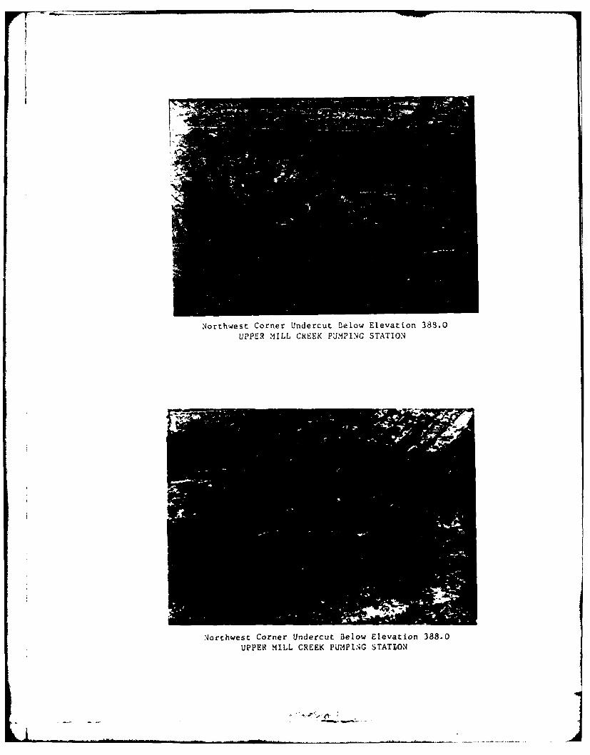
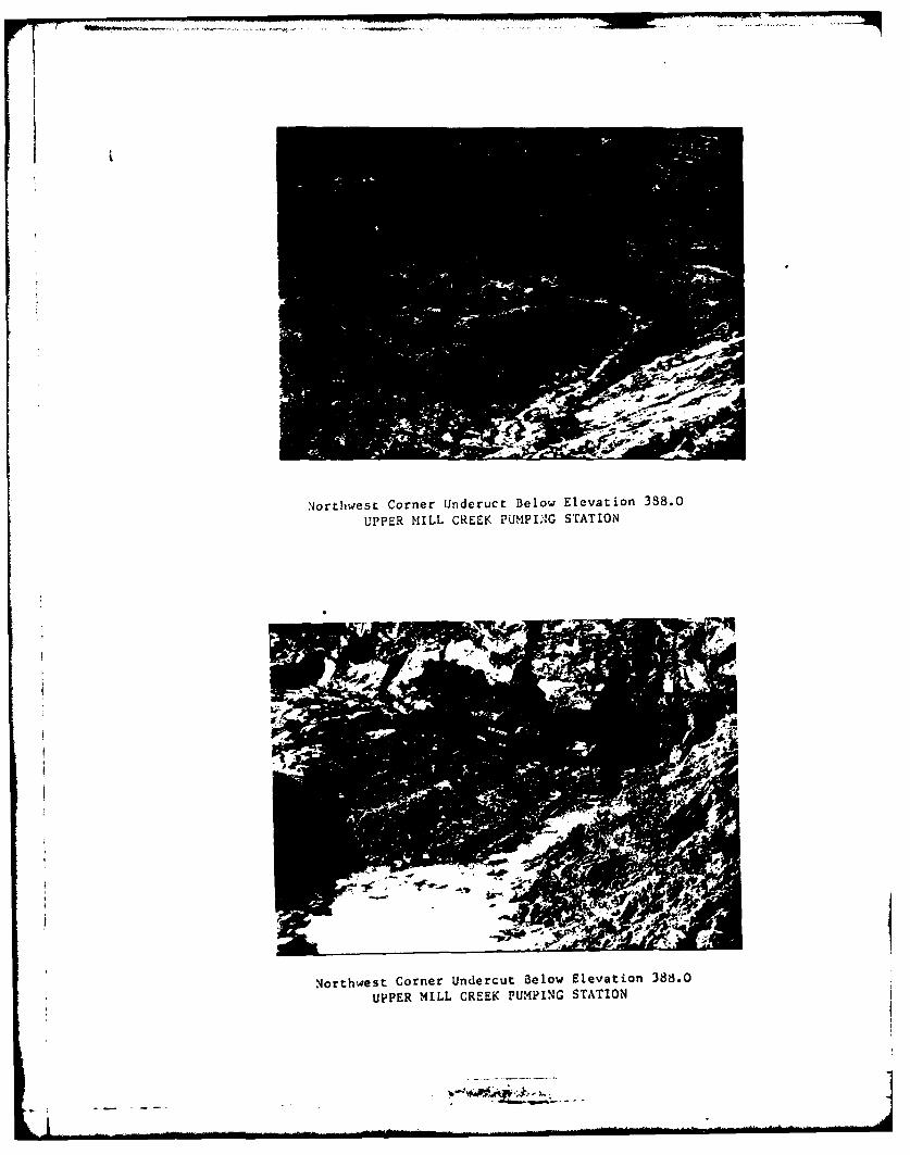
a. Upper Mill Creek - When the contractor had excavatedto elevation 388 on 6 November 1981, it became apparent by visualobservation that the silty clay had not been removed over the entirefoundation area. Approximately one-third of the foundation on the southside of the pump plant was acceptable; the clay had been completelyremoved and the in-situ pervious sand had been exposed. On the north sideof the foundation, large seams or lenses of the clay were randomly interspersedin the sand. Some test pits were dug and it was determined that as much asfive or six more feet of the clay lenses would need to be removed to exposethe sand. The clay lenses were removed by modification to the contract andrefilled with sand from the borrow area. Personnel from the Resident Office,District Office Construction Division and Engineering Division GeotechnicalBranch inspected the foundation after the clay lenses were removed and agreedthat the il-situ sand had been exposed over the entire foundation area aswas originally intended. Details of the excavation below elevation 388 areshown on Plate Number 9 and in the photographs in this supplelent.
4-2

POSSIBLE FUTURE PROBLE'IS
5-01 Conditions That Could Produce Problems.
a. There were no founding conditions encountered on thepumping stations that are anticipated to produce future problems. Theonly conditions that deviated from planned conditions were discussed inparagraph 4-02 and that condition was corrected.
b. At the Upper Mill Creek Pumping Station, theheterogeneous material discussed in paragraph 2-01c was not entirelyremoved from beneath the electrical su.bstation. Based upon adetermination by personnel from Engineering Division, the electricalsubstation will be founded on a minimum of ten feet of suitable refillmaterial placed over the heterogeneous material. It is not anticipatedthat this condition will produce a future problem but it is consideredworthy of mention.
5-02 Recommended Observations. On yearly inspections and afterevery flood condition has receded, backfill around all plants should bemonitored for any settlement or indications of problems. The silty, sandymaterial at the Riverport Station used for constructing the electricalsubstation foundation and for backfill at the pumping station shouldwarrant specific observaLion. All subsurface drains should be inspectedto insure that they are functional and not cloa-ed; specific emphasisshould be placed on tiie subsurface Jraina,;e systen at the Upper HillCreek Station. The electrical substation at the Upper Mill CreekStation should be monitored for any indication of settlement. It isalso recommended that the structure walls at all stations be inspectedfor settlement cracking and the alignment of the discharge pipes bechecked for settlement.
5-
C i -

;XwM
I j I
-~~~~~~ k 'r ,,%..-...

* I -wt VtM mgI1 1.6.44
-. -
9 Mg~N~qmp
,. W5A"~'
mm~m
* m
9Me g.
ma.ma
N C maA N
I.-.-
*~ I...1 - * * -
* -. ** *w- .-. - - '*** -. *-,.- .*~ ~ **,~.. ~ .*-I*.~* ~

S SA
M..
.*. 4 A IVI 54
L t
aHmuw .

a ... -
A. ~'' *-~A' - ~
*r. ,~.
.LV I
I * ~
~ ~ ;1-- S.-----
* *
~ t I -.
4 ___
~ a. -.
V
,- . . rn-rn
----- V -

I J-
% a nowi -m
_____________I~* __v

--
-lII~<AZ/
~ ~
a--
-~ I * --
-- -. -
* ----------- ~11 -~4
- - - - -
~ ---
- - - - - -.
mYSsmIU~,a~.
-~ 4
r5- ~*
- Al
~: *;,-
* *~ -
..- ** *-- -~*~t * *
* I

I -
Y~,, ~ ~
I-~i j I~
h1 I'! 4
~~ ______
a J
IL - -
~aW~r~ -
mu
PLATE S m-ft&,

m____________________ MU
pa pIto
w~IT:.MAN
3 v
'a-. -t -~
k~.Z ~
II
.. ,~

-r -
Ak

:1
- ... -~
-l - - -
- -: *
- K..____:1'
-~
S~-uw-~=-- -- -
- -
et- ~
PLATL# *~.7-- - -. . - L~2..
MCI-I
LA--
WSW
j --
LaiW -

_________
sore

I-,
if~Lh
415 13.
a~.t- r*
IIK ~'1 4
IIi
I.A-.
,1
- I
*
p .
I
I'a
* I U.
.........
u MMOeT Aare s
* egaM L Gas"

16..
Ir.
I -. . .do

it I,It pIi
'A ;!

it~ A
It
- pc

ifi
1%I ItIl
Il k Il
/k

North Side Excavation at Elevation 388.0UPPER AIILL GR~EEK PUMPING STATION
East Side Excavation at Elevation 388.0
UPPER M4ILL CREEK PUMPING STATION
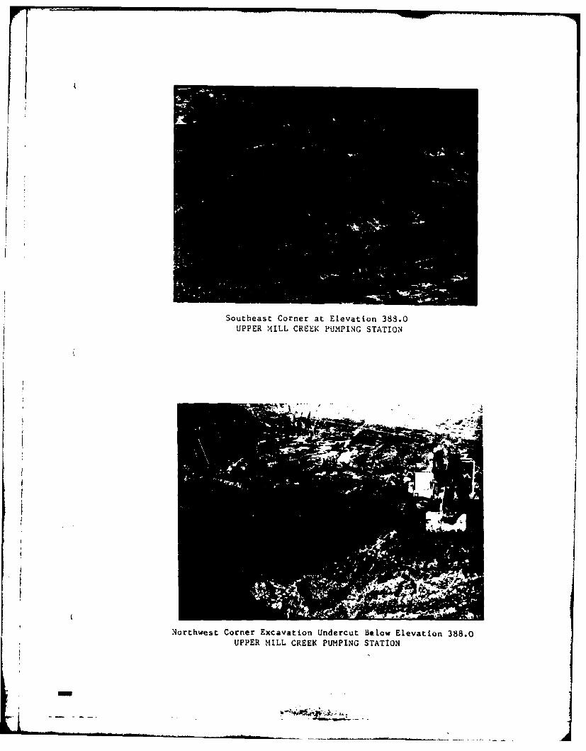
Southeast Corner at Elevation 383.0UPPER MILL CREEK PUMPING STATION
Northwest Corner Excavation Undercut Below Elevation 388.0UPPER MILL CREEK PUMPING STATION
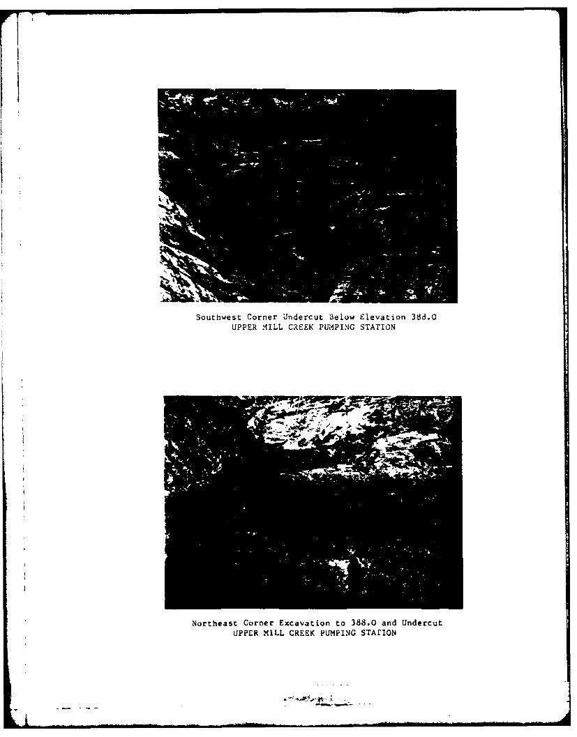
Southwest Corner Undercut B3elow Elevation 388.0UPPER MILL CREEK PUMPING STATION
Northeast Corner Excavation to 388.0 and UndercutUPPER MILL CREEK PUMPING STArION

Northwest Corner Undercut Below Elevation 388.0UPPER MILL CREEK PUMPING STATION
Northwest Corner Undercut Below Elevation 338.0UPPER MILL CREEK PUMPING STATION
Northwest Corner Undercut Below Elevation 389.0UPPER MILL CREEK PUMPING STATION
Northwest Corner Undercut 3elow Elevation 388.0
UPPER MILL CREEK PUMPING STATION

.AL',
North Side Undercut Below Elevation 338.0
UPPER MILL CREEK PUMPING STATION
Southeast Corner Undercut Below Elevation 388.0
UPPER MILL CREEK PUMPING STATION
ri -

Northeast Corner Undercut 3elow Elevation 383.0)UPPER M1ILL CREEK PUMPING STATION
Niorthwest Corner Undercut Below Elevation 388.0UPPER MILL CREEK PUM11PING STATION4
Northwest Corner Underuct Below Elevation 388.0
UPPER MILL CREEK PLJMPUJNG STATION
Northwest Corner Undercut Below Elevation 388.0
UPPER MILL CREEK PUMPING STATION

3orthwest Corner Backfill Undercut to Elevation 338.0UPPER MILL CREEK PUMPING STATION
Southwest Corner Undercut Below Elevation 388.0UPPER MILL CREEK P1JMPLING STATION

Jortheast Corner Foundation Elevation 388.0After Undercut and Refill
UPPER MILL CREEK PUMPING STATION
II
Northwest Corner Foundation Elevation 388.0
After Undercut. and Aefill
UPPER MILL CREEK PUMPING STATION
i
'1

South~west Corner Foundation Elevation 388.0UPPER MILL CREEK PUMPING STATION
North Side Foundation Elevation 388.0After Undercut and Refill
UPPER MILL CREEK PUMPING STATION

Northwest Corner Foundation PreparationElevation 388.0 After Refill Undercut
UPPER MIILL CREEK PUMPIG STATION
Northeast Corner Foundation Preparation
Elevation 388.0 After Rlefill Undercut
UPPERI HILL LREEK PUMPING STATION
3our!hwest Corner Foundation Prep3rationElevation 368.0 After Refill Undercut
UPPER .MILL CeCEK PU'1PI.4G STATIO24
West Side Foundation Preparation
Elevation 388.0 After Weill Undercut
UPPER MILL CREEK PUMPING STArio,4

r7
,4orthwest Corner Foundation PreparationElevation 3b8a.0 After Refill of Undercut
UPPER MILL CREEK PUMPING sTrATIO4
Looking South Foundation Preparation
Elevation 338.0UPPER M'ILL CREEK PUM4PING STATIO)N

Stone Filter for Drainage SystemUPPER MILL CREEK PUMPING STATION
Northwest Corner Foundation PreparationElevation 388.0 After R~efill of Undercut
I UPPER M1ILT.. CREEK PUMPING STATION

Loukin& *4est Installation of Stune Filter MaterialUJPPER tfILL CREEK PUk'IP[NG STATION
Northwest Corner Installation of Stone Filter MaterialUPPER HILL CREEK PUM1P1.G STATION
-I

Looking 4est Installation of Lateral DrainsUPPER~ MILL CREEK PUMPING STATION
Installation of Lateral orainsUPPER MILL CREEK PU'4PING STATION
-- A

Installatiun of Lateral DrainsUPPER MI1LL CREEK PUMPIN6 STATI93
Stone Filter M!aterilUPPER M4ILL CREEK PUMPING STATION

Excavation of FoundationLOWER MILL CREEK PUMPING STATION
FoundationLOWER MILL CREEK PUMPING STATION

FoundationRIVERPORT PUMPING STATION
Foundation for Electric SubstationRIVERPORT PUMPING STATION

r
Foundation and Borrow AreaRIVERPORT PUMPING STATION
Founda tionRIVERPORT PUMPING STATION