Embed Size (px)
Citation preview

fAD-A240 196
flI~~II ~~I~IBI ~IIl I~FINAL TECHNICAL REPORT __
T.H. LinUniversity of California, Los Angeles
Contract Tile: Fatigue Crack InitiationContract Number: NOO-14-86-K-0153Work Unit Number: 4324-766Scientific Officer: Yapa RajapakseP.I. and Affiliation: Professor T.H. Lin, Professor
Department of Civil EngineeringUniversity of California, Los AngelesLos Angeles, CA 90024-1593
TABLE OF CONTENTS
1. Introduction
a) Dependency of Slip on Resolved Shear Stressb) Previous Theories"
II. Present Micromechanic Theory ELP .L0 19911
a) Analogy of Inelastic Strain and Applied Forces
b) Initial Stress Field
c) Gating Mechanism provided by Stress Field
d) Supporting Experimental Observations
Il. The main accomplishments of this research are as follows:
a) Fatigue crack initiation under cyclic torsion:
b) Fatigue Crack Initiation under Combined Cyclic Axial Loading and Torsion:
c) Interaction of two slip planes in fatigue crack initiation:
d) Interaction of Fatigue and Creep in High-Cycle Fatigue Crack Initiation:
e) Overload Effect on the Retardation of Fatigue Crack Initiation:
f) Fatigue Crack Initiation in Ordered Alloys:
IV. Index of technical reports published:
V. Index of all publications: D-TrRBfl- T N"TAyktq A-ApPrOv"d for ptbi'o r,g;
VI. References D-S lution ull.yz, r,
DEFENSE TECHNICAL INFORMATION CENTER
9107134
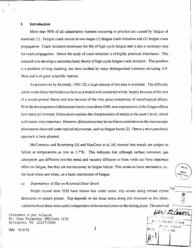
I. Introduction
More than 90% of all catastrophic ruptures occurring in practice are caused by fatigue of
materials [1 ]. Fatigue crack occurs in two stages (1) fatigue crack initiation and (2) fatigue crack
propagation. Crack initiation dominates the life of high-cycle fatigue and is also a necessary step
for crack propagation. Hence the study of crack initiation is of highly practical importance. This
research is to develop a micromechanic theory of high-cycle fatigue crack initiation. This problem
is a problem of long standing, has been studied by many distinguished scientists including N.F.
Mott and is of great scientific interest.
As pointed out by Kennedy, 1961 [2], a large amount of test data is available. The difficulty
seems to see these multitudinous facts as a related and connected whole, largely because of the lack
of a sound general theory and also because of the very great complexity of metallurgical effects.
With the development of dislocation theory since about 1940, new explanations of the fatigue effects
have been put forward. Dislocation explains the characteristics of metals at the atomic level, which
is of course, very important. However, dislocations may be too fine to correlate even the macroscopic
phenomena observed under optical microscope, such as fatigue bands [2]. Hence a micromechanic
approach is here adopted.
McCommon and Rosenberg [3] and MacCone et al. [4] showed that metals are subject to
failure at temperatures as low as 1.7'K. This indicates that although surface corrosion, gas
adsorption, gas diffusion into the metal and vacancy diffusion to form voids can have important
effect on fatigue, but they are not necessary to fatigue failure. This seems to leave mechanics, i.e., a ,i
the local stress and strain, as a basic mechanism of fatigue. " ,s:e.
a) Dependency of Slip on Resolved Shear Stress
Single crystal tests [5,6] have shown that under stress, slip occurs along certain crystal 7or
directions on certain planes. Slip depends on the shear stress along this direction on this plane, 'E01
called resolved shear stress and is independent of the normal stress on the sliding plane. The resolved :-----------
Statement A per teleconDr. Yapa Rajapakse ONR/Code 1132 - b i . ..-_Arlington, VA 22217-5000 ,
N~ '~J 9l/99 crNWW 9/9/91 2D iZ. .~
shear stress to initiate or to cause the continuation of slip is called the critical shear stress. This
dependency of slip on the resolved shear stress under monotonic loadings has been found to hold
also under cyclic loadings [7].
b) Previous Theories
Forsyth and Stubbington 1954 [8] reported the detection of extrusion in slip bands during
fatigue of some aluminum alloys. Thompson, Wadsworth and Louat [9] and Hull [ 10] detected the
extrusion process in both copper and aluminum. This initiation of extrusion process was also
observed by Meke and Blochwitz [ 11 ] and Mughrabi [ 12] in their studies of persistent slip bands.
Following the clue, which the observations on extrusions and intrusions in slip bands have
provided, a number of theories of fatigue crack initiation have been proposed by different very
distinguished investigators. For example, Mott [ 13] proposed that a screw dislocation repeats its
path through cross slip. He considered a column of metal containing a single screw dislocation
intersecting a free surface. When the dislocation travels a compiete circuit, the volume contained
in the circuit is translated parallel to the dislocation, this causes the metal to extrude. This mechanism
does not explain why the dislocation under cyclic stressing, does not oscillate back and forth along
the same path rather than traversing a closed circuit. Clearly some form of gating mechanism is
required to convert the back and forth oscillations into unidirectional circuits. Cottrell and Hull
[141 proposed that Frank Read sources exist on two intersecting slip planes and a complete cycle
of forward and reversed loading results in an extrusion and intrusion. Such a model would predict
the extrusion and intrusion to form in neighboring slip bands and to be inclined to each other, but
they have been found to occur in the same slip band and to be parallel to each other. Wood [15]
proposed a simple model of a single operative slip system. An unidirectional stressing causes layers
of metal to slide in the same direction: but forward and reverse stressing causes different amounts
of net slip on different planes and results in peaks and valleys. However, this model does not explain
3

why, under an alternate loading, the slip continue to monotonically deepen the valley and raise the
peaks as observed in experiments. Drawbacks of other theories have also been discussed by Kennedy
[2].
For a dislocation to glide, it (1) must glide along a certain direction on a certain crystal plane
and (2) must subject to a resolved shear stress equal to or greater than the critical shear stress. The
above mentioned theories show the possible paths of dislocation movement to satisfy condition (1)
but the resolved shear stress field caused by the dislocation movement that has significant effect
,,n (2) was not considered. In the present study, this important effect of this stress field, which
supplies a natural gating mechanism, is shown.
II. Present Micromechanic Theory
When the resolved shear stress in a slip system in some region of a polycrystal reaches the
critical shear stress, slip can occur in this system. If the loading on the metal is removed, this slip
remains and causes a residual stress field. If a different loading is then applied, the resolved shear
stress is the sum of the residual and the applied stresses. In calculating this residual stress field,
the analogy between the inelastic strain and the applied force, developed by Lin, 1968 is here used.
The analogy is briefly reviewed here.
a) Analogy of Inelastic Strain and Applied Forces
Referring to a set of rectangular coordinates, the strain component is composed of the elastic
part denoted by single prime and the inelastic part denoted by double prime
ev = ey+ei.' (1)
Thermal, creep and plastic strains are considered to be the inelastic strain. Neglecting the anisotropy
of elastic constants, the stress is related to the elastic strain as
t,, =+ 2.t ,
, = (8,x(E - E") + 21i(ej - e,) (2)
4

where k and g. are Lame's constants, E is the dilatation. The condition of equilibrium within a
body of volume V is
tud +F, = 0inV, (3)
where the subscript after the comma denotes differentiation, the repetition of the subscript denotes
summation from one to three, and Fj denotes the body force per unit volume along the xi axis. At
any point on the boundary F with normal v, the i-com-ponent of the surface traction per unit area
St" , can be written from the condition of equilibrium as
SIv) = ijvj on F (4)
where v, is the cosine of the angle between the normal v and the xi axis. Substituting (2) into (3)
and (4), we obtain
8 X., + 2te, - (6,jXe 1; + 24te".) + F, =0 (5)
Sv') = v[8,,X + 2geje - (86,X."+ 2ge",)] (6)
It is seen that - (5,XEO- + 2lie " ) and (6uXE" + 2.w~j)v, are equivalent to F and S(v) in causing the
strain field e,,, and are here denoted by F, and si , respectively, giving.
8,)X.Oj + 2Wteuj + Fj + Fi = 0 (7)
Sv M -(v)
S( + Sv = v,(8X)V + 2geje). (8)
Hence, the strain distribution in a body with inelastic strain under external load is the same as that
in an elastic body (no inelastic strain) with the additional equivalent body and surface forces F, and
*i .This reduces the solution of stress field of a body with known elastic strain distribution to the
solution of an identical elastic body with an additional set of equivalent body and surface forces.
This gives the same results as the famous process of imaginary cutting, relaxing, restoring, welding,
and relieving in the noteworthy paper by Eshelby, 1957, on ellipsoidal inclusions [16].
5

If the inelastic strain is due to thermal strain alone with thermal coefficient of expansion a
and temperature T, we can write
ei,= 6, 1aT, E =ei = 3oT
Then the equivalent body and surface forces becomes
F, = - (2k + 2.) a T,i
-'V)Si = vi(3,+2.)aT
This is the well-known Duhammel' s analogy [ 17], between temperature gradient and the body forc,-
in an elastic medium. Hence Duhammel's analogy is a special case of the general analogy for
inelastic strain.
This analogy has been used by Lin [18] in the derivation of the macroscopic polycrystal
stress-strain and stress-strain-time relations under radial and non-radial loadings from those relations
of the component crystals.
b) Initial Stress Field
Imperfections like dislocations exist in all metals and cause initial stress fields. For a slice
of metal to extrude out of a surface, positive shear deformation must occur on one side of the
extrusion and negative shear on the other. The initial stress field t near the free surface favorable
for the initiation of extrusion is one with positive resolved shear stress above the slice and a negative
one below the slice. Referring to Fig. 1, x, and x2 are a set of rectangular axes on a longitudinal
section of polycrystalline metal subject to alternate tension and compression along x2 - axis. a and
are another set of rectangular axes with B along the slip direction and a along the normal to the
slip plane of the most favorably-oriented crystal at the free surface. Both a and 3 make 450 with
x, and x2 axes. From the analogy of applied force and plastic strain as discussed previously, an
initial stress field caused by a linear variation of e. from zero at the free surface to maximum at
6

the interior boundary of this crystal has been calculated [ 19] and is found to give a positive shear
stress in P, and negative in Q. This initial shear stress field clearly is favorable for the initiation of
an extrusion.
Consider a perfect crystal. If we cut a slit through this crystal and force a sheet of metal of
one atom thick into the slit, a pair of parallel edge dislocation A and B of opposite signs forming
an interstial dipoles is produced as shown in Fig. 2. If we cut a rectangular block along the dotted
line, the free length of this block will be one atomic spacing more than the corresponding length of
the hole. If there are n such dipoles in a length of N atomic spacings, this will give an initial strain
e/, of n/N. Hence this initial strain can be caused by an array of dislocation dipoles. This array of
dipoles was suggested by Lin and Ito [20] in 1969 as a possible way of providing the initial strain
to cause the favorable initial stress field. Recently these dislocation dipoles were observed in fatigue
specimens as ladder structures in persistent slip bands [21].
7

MOST FAVORASLY 3 ~Q*;AE IA'N • iSURFACE
NORMAL TO
SUP OIRZCTICmI
E 2UNOARY
Fig. 1. Most favorably oriented crystal at free surface
ye
IA
-VI I
__I
B
Fig. 2. A dislocation interstitial dipole
8

c) Gating Mechanism provided by Stress Field [22,23 /
A tensile loading causes a positive resolved shear stress T" in the whole crystal. In P the
resolved shear stress will be the sum of t' and 't. This stress will be the first to reach the critical
shear stress t, to cause slip. This slip causes a residual stress tR. Due to the continuity of the stress
field 8, slip in P relieves not only the positive shear stress in P, but also in its neighboring region
including Q. This keeps the positive shear stress in the neighboring region from reaching that of
P during the forward loading. Hence only P slides in the forward loading. The relief of positive
resolved shear stress has the same effect as increasing negative resolved shear stress. During the
reversed loading, Q has the highest negative resolved shear stress and hence slides. This slip causes
the relief of negative shear stress not only in Q but also in its neighboring region including P. This
relief of negative resolved shear stress has the same effect as increasing positive resolved shear
stress, thus causing P to be more ready to slide in the next forward loading. During the next forward
loading, P has the highest positive shear stress and hence slides. This slip again relieves the positive
shear stress and increases the negative shear stress in Q thus causing it to slide in the next reversed
loading. This process is repeated and gives the natural gating mechanism to cause alternate sliding
in P anct Q. As a result, positive slip in P and negative slip in Q increase monotonically with cycles
of loading and produce an extrusion. The interchange of the signs of the initial resolved shear
stresses in P and Q will yield an intrusion instead of an extrusion. This theory explains the observed
monotonic raising of extrusions and deepening of intrusions, and also shows that such an initial
stress field can be obtained by a given plastic strain distribution which can be caused by a distribution
of dipoles [ 19] in the region between P and Q. Same mechanism also exists in cyclic torsion.
d) Supporting Experimental Observations
The above theory has many experimental evidences. Few of these are listed below.
I. Formation of new slip lines in reversed loading. Tests on single aluminum crystals under
cyclic loading in tension and compression by Charsley and Thompson [24], have shown that
9

a reversal of stress after a prior forward deformation gives rise to new parallel slip lines.
Buckley and Entwistle [251 found that on an aluminum crystal, slip lines formed during
compressive loading lie between those formed in prior tensile loading. These and other tests
show the occurrence of slip lines in the reversed loading to be very close but distinct from
those formed in forward loading just like P and Q in the proposed theory.
2. Gough [26] tested two single crystals in cyclic torsion with superimposed static tensile load.
The test aims to determine whether the maximum shear stress or the maximum range of shear
stress determines slip under alternate loading. The maximum shear stress in this case acted
on a plane different from that with maximum range of shear stress. It was tound that the
maximum shear stress determined the slip system only in the very early stages of the test but
very soon the slip changed to the slip system with maximum range of stress. This agrees with
the present theory since it shows the dependence of the build-up of plastic strain on the range
of stress.
3. X-ray reflection patterns of monotonically and cyclically loaded specimens are very different
[15 1. The latter retain the discrete spots like that of annealed metals while the former do not.
Fig. 3. This shows that slip occurrence in alternate loadings does not cause lattice straining
in the bulk of the metal. Under cyclic loading, the positive shear slip line (like P) are closely
located with the negative ones (like Q). At some distance from the slip lines, the stress field
caused bv positive slip in P is balaned by that caused by negative slip in Q. Hence, the stress
field and the lattice strain is small in the bulk of the metal. Under monotonic loadings, the
slip in all slip lines tends to be all of the same sign and causes a significant average plastic
strain which causes an appreciable stress field and elastic lattice strain in the bulk of the metal.
The above theory accounts for the different X-ray reflection patterns of the monotonically
and cyclically deformed metals.
10

4. Woja and Bender [271, tested copper circular rod specimens subject to torsion. The specimens
were electropolished and then scratched as markers with a pad carrying 0.51.1 diamond dust.
Some specimens were subject to alternate torsion and some subject to single twist through
large angles. The deformation in a typical slip band AB of a specimen subject to a single
twist is shown in Fig. 4; a, b, c are typical scratches which were initially straight and con-
tinuous. It is seen that the single twist caused the scratches above AB to displace relatively
to those below. Fig. 5 shows the deformation under cyclic torsion with scratch d. e,f and a
typical fatigue band DC. It is seen that the cyclic deformation caused no relative displacement
of the scratches left and right of the fatigue bands, but within the band. the scratches have
displaced equally up and down producing a zigzag. A severely slid line with positive shear
such as P is sandwiched by two less severely slid lines with negative shear such as Q. This
clearly verifies with the theory proposed.
Figure 3. (a) Sharp X-Ray Reflection from Annealed a-Brass.
(b) From Same Specimen as (a) After a Unidirectional Strain 150x 0.5' Twist.
(c) From Same Specimen as (a) After 1500 Reversals of PlasticStrain 0.50 Twist and Showing Same Reflection as (a).
.... 2- -11

C
Aba
Fig. 4. Initially Straight Scratches a, b, c are displacedunidirectionally by static slip band AB.C1
l'it . ~Cyclic Slip Band CD Produces no Overall displacement of Scratches d. e. f. withinthe slip band the scratches are displaced equally backward and forward
12

Fig. 6. Grain Boundary at the End of Slip Bands in Fatigued Aluminum.
13

5. Forsyth [281 has given a picture showing the moving of grain boundary at the end of a slip
band. It is seen in Fig. 6 that snears of opposite signs are closely associated.
6. Recent tests by Woods [29] of single copper crystals have shown that from the very early
stages of fatigue tests the specimens develop into a state containing two phases: a soft phase
with persistent sli, bands into which the deformation tends to concentrate, and a hard phase
with almost inactive matrix which is comparatively dislocation-free. The regions in P and
Q slices of the present model correspond to the observed soft-phased and those outside of P
and Q correspond to the hard phased regions.
7. Recently Meke and Blochwitz [11] have indicated that persistent slip band protrudes out in
two sides of a single crystal under cyclic loading. If the initial stress varies from positive to
negative in P and from negative to positive in Q, cyclic loading will cause extrusions on both
faces of the single crystal. The movement of the subgrain boundaries Fig. 11 as shown by
Meke and Blochwitz seem to agree well with this proposed theory.
Using the amount of local plastic strain in P as an estimate of the early fatigue damage [301,
this theory has been used to calculate the effects of mean stress [31], grain size and strain hardening
[321 on this fatigue damage under cyclic tensile and compressible loadings. The calculated results
seem to agree, in general, with test results.
Fig. 7. Extruding on Two Opposite Surfaces of a single crystal. PSB
Persistent Slip Band SGB Subgrain Boundary Taken from Ref. 11
The above explains the deficiencies of the previous theories wiui shows how the present
approach removes these deficiencies and agree with experimental including microscopic metal-
lurgical observations.
14

Ill. The main accomplishments of this research
a) Fatigue crack initiation under cyclic torsion:
Single crystal tests have shown that extrusion and intrusion occurred on a slip plane along
the most highly stressed slip direction and did not occur when the direction was parallel to the free
surface. In cyclic tension and compression, the slip direction of the highest stressed slip system in
the most favorably oriented crystal inclines 450 with the free surface. In a circular shaft under
torsion, the maximum shear stress occurs along the circumferential direction (parallel to the free
surface) on a plane normal to the shaft axis. Hence, the extrusion and intrusion process will not
occur in the slip system with maximum shear stress. But this process may occur on some crystal
with a slip plane normal to the shaft and a slip direction making angle 3 with the circular boundary.
Two thin slices spaced at 0.1 p.m apart were considered. The top slice is assumed to have a positive
initial resolved shear stress and the bottom one, a negative shear stress. The microstress fields
caused by plastic strain in these two slices were calculated and shown to provide the gating
mechanism for the two slices to slide alternately just as in the case of cyclic tension and compression
as developed by Cooley and Lin, 1986 [33]. Lin et al., 1987 [34]. Displacement component normal
to the free surface is taken as a measure of the amount of intrusion, which in turn, is taken as a
measure of crack initiation. It was found that the angle 3, giving this maximum displacement
component increases with the cyclic torsional stress. Under the same initial shear stress, and the
same range of shear stress with zero mean stress, the growth of the crack initiation is much larger
in cyclic tension and compression than in cyclic torsion for small range of shear stress. However,
as the amplitude of the range of shear stress is increased, the rate of crack initiation for cyclic torsion
does catch up with that of cyclic tension and compression. This agrees with test results reported
by Tanaka et al. in their paper "Fatigue Strength 7075-T6-AL.AL. under Combined Axial and
Torsional Loadings", published in Fatigue Eng'g Material & Structure, Vol. 7, p. 195, 1984. The
detail of the present work is shown in the paper "Fatigue Crack Initiation under Cyclic Torsion",
published in the Journal of Applied Mechanics Vol. 53 p. 550-554 1986.
15

b) Fatigue Crack Initiation under Combined Cyclic Axial Loading and Torsion.
Under combined axial loading and torsion on a circular shaft, the stress on the outer layer of
the shaft is under a combined axial and shear stresses in a plane. The principal planes giving extreme
value of normal stresses are shown by the dotted line Fig. 8. The planes giving maximum shear
stresses are making 45' with the principal planes. Now we have two planes of maximum shear
stresses. One is 7 making 450 with xy-plane causing a fatigue crack initiation same as that caused
by pure axial loading.
Fig. 8. Combined Axial and Shear Loading
Due to the presence of torsional stress T,, the other one is on a plane making 45' with the two
principal planes.
+
The later is treated like the shear stress due to pure torsion. Among these two crystals. the one with
higher crack initiation rate gives the crack initiation rate of the polycrystal. This work was presented
in the 3rd International Conference on Fatigue and Fatigue Thresholds and was very well received.
This work was published in the proceedings of this conference, (1987).
16

c) Interaction of two slip planes in fatigue crack initiation:
Referring to the figure 2, for a slice R to extrude out of the free surface, positive shear
deformation must occur in P and negative in Q. The initial shear stress field favorable to this
deformation is one positive in P and negative in Q. These initial shear stress can be caused by an
inelastic tensile strain el ?, which can be caused by an array of interstitial dislocation dipoles.
These dipoles have recently been observed in slip bands as ladder structure in fatigue specimens
and produce an initial tensile strain along the extrusion direction in R. If R were cut out from the
metal, the unconstrained length of R would be longer than the slot in the metal by an amour.., which
Mughrabi called "static extrusion" [35]. If it were forced back into the slot in the metal, R would
be subjected to a compressive longitudinal stress ,,, which causes the positive and negative initial
shear stress T4 in P and Q. Under cyclic loading, plastic shear strain , builds up in P.Q. This ,
in P is about the same as in Q but 7p varies along a-direction. Let "t" denote the thickness of slices
P, Q. The displacement along a-direction in R is then ty,. It's differentiation with respect to a
gives a tensile strain in R. This tensile strain relieves some initial compressive stress in R. Further
cyclic loading causes tensile stress in some part of R. This tensile stress causes a resolved shear
stress in a second slip system. When this shear stress reaches critical, the second sliding plane
slides. This slip causes plastic tensile strain, which has the same effect as the initial tensile strain.
Hence, this secondary slip helps P, Q to slide and causes the extrusion to grow beyond the "static
extrusion" as reported by Mughrabi [35] in his experimental study of fatigue. The detail of this
study is shown in the paper on "Micromechanics of an Extrusion in High-Cycle Fatigue" [36) by
T.H. Lin, S.R. Lin and X.Q. Wu published in Philosophical Magazine A, Vol. 59, pp. 1263-1276,
1989.
d) Interaction of Fatigue and Creep in High-Cycle Fatigue Crack Initiation:
Single crystal tests at room and elevated temperatures below one half of the melting tem-
perature, have shown that under stress, slip occurs along certain directions on certain planes. This
slip depends on the resolved shear stress. This dependency, known as Schmid's Law, holds also
17

under cyclic loadings. An aluminum polycrystal under a cyclic loading in tension and compression
at an elevated temperature is considered. Extrusions and intrusions are preferable sites of fatigue
cracks. The extent of extrusions or intrusions are taken as a measure of fatigue crack initiation.
Single aluminum crystal tests at an elevated temperature has shown that the stress-strain-time
relation can be approximately represented by the expression
,¢ = A(,t,4- )
where b is the resolved shear strain rate, TO the resolved shear stress, T' is the critical shear stress
and A is a constant.
Consider a most favorably oriented crystal at a free surface of the polycrystal as shown in
Fig. 1. For an extrusion to start in a thin slice R sandwiched between two slices P and Q, positive
shear must occur in P and negative in Q. An initial stress field to cause such sliding can be provided
by an initial tensile strain e' in R. The repetition of Greek subscript does not denote summation.
This initial tensile strain can be provided by a row of interstitial dislocation dipoles and a negative
e, by vacancy dipoles.
A tensile loading T2 2 on the polycrystal (Fig. 1) produces a positive A in the whole crystal.
Taking TI to be positive in P and negative in Q, we have x' + TA in P reaching the critical shear stress
T' first: and hence, P slides to yield creep strain e' . Due to the continuity of stress field, slip in P
relieves not only the positive shear stress in P but also in Q. Hence, this slip increases the negative
resolved shear stress in Q to cause Q to slide more readily in the reverse loading. The negative slip
in Q relieves the negative shear stress not only in Q, but also in P, thus causing P to slide more
readily in the next forward loading. This process is repeated for every cycle thus providing a natural
gating mechanism for a monotonic buildup of local slip strain eO in P and Q, pushing R out of the
free surface and starts an extrusion. Interchanging the signs of the initial stresses in P and Q initiates
an intrusion instead of an extrusion. This theory is extensively supported by metallurgical obser-
vations.
18

The initial tensile strain e' in R causes the initial positive and negative shear stresses in P
and Q. This, in turn, causes the growth of the extrusion. As the extrusion grows under cyclic
loading, the slice R increases in length. This elongation causes the compression in R to decrease.
A question has been raised as to whether the extrusion growth will cease after the extrusion has
reached the static extrusion. The residual tensile stress TR. caused by elongation in R due to extrusion
can cause changes of resolved shear stresses in all twelve slip systems. The resolved shear stress
in one slip system may reach the critical and slide. The creep strain e c caused by slip in this system
has a tensor component e' just like e' in causing the positive and negative (, , respectively, in P
and Q. This secondary slip has been shown to increase greatly the extent of extrusion and intrusion
in time-independent slip. The present study shows that this secondary slip also increases this extent
of intrusion and extrusion in fatigue with creep. Creep strain under two different frequencies of
loading were calculated. The results are published in the Journal of Applied Mechanics, Vol. 57,
p. 807, Dec. 1990 [37].
e) Overload Effect on the Retardation of Fatigue Crack Initiation:
Copper single crystal tests by Hunsche and Neumann, 1986 have shown that under constant
plastic strain amplitude of 0.20% the resolved shear stress increases from 32 MPa to 35 MPa within
500 cycles. The nucleation of persistent slip bands PSB is accompanied by a slight softening down
to 32 MPa again. Then the shear stress amplitude stays constant. An overload causes more slip
bands to become active. This softening after the peak stress causes a number of PSB's to continue
sliding after the overload. A number of fatigue bands of different initial resolved shear stresses are
assumed to exist in a most favorably oriented crystal at a free surface of a polycrystal. Without
overload, only the band with the highest initial shear stress slides. With overload, many more PSB's
become active and continue to slide after the overload. Slip in one PSB relieves some resolved
shear stresses in other slip bands. The rate of slip in the band with highest slip rate decreases. The
highest slip at the free surface is used as a measure of crack initiation. Hence overload generally
19

causes retardation of fatigue crack initiation. Analytical method and numerical analysis have been
made. The results were presented in Fatigue 90, the 4th International Conference on Fatigue and
Fatigue Thresholds held in July, 1990 in Hawaii, and published in its Proceedings, Vol. I, pp.
489-492, 1990 [38].
f) Fatigue Crack Initiation in Ordered Alloys:
Tests on Ni3A I and Fe C-V ordered interatomic alloys show that long range order substantially
increased the life in high cycle strain-controlled fatigue. Order favors planar slip by inhibiting
cross-slip and/or multiple slip. Electron microscopic study of fatigue crack initiation in Ni 3A1 single
crystals by Hsiung and Stoloff shows that (111) primary slip bands first form. Then some of the
bands become coarser. The coarse primary slip bands eventually developed into PSB-like bands.
It was observed that cracks developed at PSB/matrix interface. The high-.ycle fatigue crack ini-
tiation of disordered and ordered intermetallic alloys have been analyzed using the micromechanic
theory. It has been found that the high-cycle fatigue crack initiation life of this ordered alloy is
much longer than that of the disordered alloys. This explains the experimental results. The details
of the analysis will be shown in the UCLA Engineering Report ENG-CE-91-01, Aug. 1991 [39].
IV. Index of technical reports published:
"Interaction of Two Slip Planes on Extrusion growth in Fatigue Band", Lin, T.H., Lin, S.R.,
and X.Q. Wu, UCLA Engineering Department, ENG-87-11, 1987.
"Reciprocal Theorem of Residual Stress and Inelastic Strain", Lin, T.H., Lin, S.R., X.Q. Wu,
and Chen, Q.Y., UCLA-ENG-88-09, 1988.
"Micromechanics of an Extrusion in Fatigue", Lin, T.H., Lin, S.R. and X.Q. Wu, UCLA-
ENG-88-07, 1988.
"Micromechanics of an Extrusion in High-Cycle Fatigue with Creep", Lin, T.H., Lin, SR.
and X.Q. Wu, UCLA Engineering Report, Eng-89-09, Sept. 1989.
20

V. Index of all publications:
"Fatigue Crack Initiation under Cyclic Torsion", Cooley, W.U. and Lin, T.H., Journal of
Applied Mechanics, Vol. 108, p. 550-554.
"Micromechanics of Fatigue Crack Initiation under Axial and Torsional Loadings", Lin, T.H.,
Lin, S.R. and W.U. Cooley, Proc. 3rd International Conference on Fatigue and Fatigue
Thresholds, held at Univ. of Virginia, Charlottesville, VA, Vol. II, pp. 941-950, 1987.
"Free Surface Effect on Fatigue Crack Initiation under Cyclic t-rsion", Abstrqt. in Proc
10th U.S. National Congress of Applied Mechanics, June, 1986.
"Micromechanics of an Extrusion in High-Cycle Fatigue", Lin, T.H., Lin, S.R. and Wu, X.Q.
Philosophical Magazine A, Vol. 59, No. 6, p. 1263-76, 1987.
"Interaction of Slip Bands in High-Cycle Fatigue Crack Initiation", Lin, T.H. and Chen, Q.Y.,
published in Micromechanics and Inhonogenity, The Toshio Mura Anniversary Volume,
Springer-Verlag, pp. 231-241, 1990.
"Overload Effect on the Retardation of Fatigue Crack Initiation", Lin, T.H., Lin, S.R. and
Chen, Q.Y., Proc. of 4th International Conference on Fatigue and Fatigue Thresholds, Vol.
I, p. 487-492, 1990.
"Micromechanics of High-Cycle Fatigue Crack Initiation", Lin, T.H., to be published in
Advances in Applied Mechanics, Vol. 28, Academic Press.
"Micromechanics of High-Cycle Fatigue Crack Initiation with Creep", Lin, T.H., Lin, S.R.
and Wu, X.Q., Journal of Applied Mechanics, Vol. 57, pp. 815-820, 1990.
VI. References
1. Puskar, A. and S.A. Golvin, "Fatigue in Materials: Cumulative Damage Processes", Elsevier,
Amsterdam, Oxford, New York, Tokyo, p. 13, 1985.
21

2. A.J. Kennedy, "Process of Creep and Fatigue of Metals", John Wiley & Sons Inc. pp. 2,
331-343, 1963.
3. McCommon, R.D. and H.M. Rosenberg, "The Fatigue and Ultimate Tensile Strengths of
Metals between 4.2°K", Proc. Roy, Soc. (London), Vol. 242A, p. 203, 1957.
4. MacCone, R.K., R.D. McCommon, and H.M. Rosenberg, "The Fatigue of Metals at 1.7°K,
Phil. Mag., Vol. 4, p. 267, 1959.
5. G.I. Taylor, "Plastic Deformation of Metals", J. Inst Metals, Vol. 62, p. 307, 1938.
6. G I. Taylor, "The Distortion of Crystals of Aluminum under Compression", Proc. Roy Soc.
A, Vol. 151, pp. 529-551, 1926.
7. E.R. Parker, "Theories of Fatigue", Mechanical Behavior of Materials in Elevated Temper-
atures, edited by J.E. Dorn, McGraw-Hill, pp. 129-148, 1961.
8. Forsyth, P.J.E. and C.A. Stubbington, "The Slip Band Extrusion Effect Observed in Some
Aluminum Alloys Subjected to Cyclic Stresses", J. Inst. Metals, Vol. 83, p. 395, 1955.
9. Thompson, N., N.J. Wadsworth N.J. and N. Louat, "The Origin of Fatigue Fracture in Copper",
Phil. Mag., Vol. 1, p. 113, 1955.
10. D. Hull, "Surface Structure of Slip Bands on Copper Fatigued at 2930, 90', 4.21K", J. Inst.
of Metals, Vol. 86, p. 425, 1958.
11. Meke, K. and C. Blochwitz, "Internal Displacement of Persistent Slip Bands in Cyclically
Deformed Nickel Single Crystals", Phys. Stat. Sol. (a) 61 p 5, 1980.
12. H. Maghrabi, "Microscopic Mechanisms of Metals Fatigue Strength of Metals and Alloys,
Vol. 3, p. 1615-38, Pergamon Press. Oxford and New York, 1980.
13. N.F. Mott. "Origin of Fatigue Cracks", ACTA Metallurigica, Vol. 6, p. 195, 1958.
22

14. Cottrell, A.H. and Hull, D., "Extrusions and Intrusions by Cyclic Slip in Copper", Proc. Roy.
Soc. (London), Vol. 242A, p. 211, 1957.
15. W.A. Wood, "Mechanism of Fatigue", Fatigue in Aircraft Structures (Edited by A.M.,
Freudental), Academic Press, New York, 1956, pp. 1-19.
16. J.D. Eshelby, "The Determination of the Elastic Field of an Ellipsoidal Inclusion and Related
Problems", Proc. Roy. Soc.,A. Vol. 241, p. 396, 1957.
17. J.M.C. Duhammel, "Memoire Sur Le Calcul des Actons Mole'zulaires Developes par les
Changements de Temperature Dans le Corpe Solides", Mem. Inst., France, Vol. 5, pp. 440-498,
1938.
18. T.H. Lin, "Physical Theory of Plasticity", Advances in Applied Mechanics, Vol. 11, pp.
255-307, 1971.
19. Lin S.R. and T.H. Lin, "Initial Strain Fields and Fatigue Crack Nucleation Mechanism", J.
Appl. Mech. Vol. 105, pp. 367-372, 1983.
20. Lin, T.H. and Y.M. Ito, "Fatigue Crack Nucleation in Metals", Proc. U.S. Nat'l. Acad. Sci.
Vol. 64, pp. 631-635, 1969.
21. Katagiri, K., A. Omura, K. Koyanagi, J. Awatani, T. Shirashi, and H. Kaneshiro, "Early Stage
Crack Tip Dislocation Morphology in Fatigued Copper", Metallurgical Transactions, A. Vol.
8A, pp. 1769-1773, Nov. 1977.
22. Lin, T.H. and M. Ito, "Mechanics of a Fatigue Crack Nucleation Mechanism", J. Mech. Phys.
Solids, Vol. 17, pp. 511-523, 1969.
23. T.H. Lin, "Micromechanics of Fatigue Crack Initiation: Theory and Experimental Obser-
vations", Mechanics of Fatigue - AMD, Vol. 47, ASME, Edited by T. Mura, pp. 41-109,
1981.
23

24. Charsley, P.. N. Thompson, "The Behavior of Slip Lines on Aluminum Crystals Under
Reversed Stresses in Tension and Compression", Phil. Mag., Vol. 8, p. 77, 1965.
25. Buckley, S.N. Entwistle, K.M. "The Bauschinger Effect in Super Pure Aluminum Single
Crystal and Polycrystals", ACTA Metallurigica, Vol. 4, p. 352, 1956.
26. Gough, H., "Crystalline Structure in Relation in Failure of Metals Especially by Fatigue",
Proc. Am. Soc. Test, Mater., Vol. 33, p. 3, 1933.
27. Wood, W.A., Bender, A.M., "The Fatigue Process in Copper as Studies by Electron Metal-
lography", Trans. Metallurigical Society AIME, Vol. 224, pp. 180-186, 1962.
28. P.J.E. Forsyth, "Some Further Observations on the Fatigue Process in Pure Aluminum". J.
Inst. Met., Vol. 82, p. 449, 1953.
29. Woods, P.T., "Low-Amplitude Fatigue of Copper and Copper - at 5% Aluminum Single
Crystals", Phil. Mag., Vol. 28, No. 1, pp. 155-191, 1973.
30. T.H. Lin, "Micromechanics of Deformation of Slip Bands Under Monotonic and Cyclic
Loadings", Reviews of the Deformation Behavior of Materials, P. Felham (ed.), Freund
Publishing House; Tel-Aviv, Israel, 1977.
31. Lin, T.H. and Y.M. Ito, "A Micromechanic Theory of the Effect of Mean Stress on Fatigue
Crack Nucleation", Proc. Air Force Conference on Fatigue and Fracture of Aircraft Struc-
tures and Materials held in Miami, Florida, December 1970.
32. Lin, T.H., and Y.M Ito, "The Influence of Strain-Hardening and Grain Size on Early Fatigue
Damage Based on a Micromechanics Theory", J. Mech. and Phys. Solids, Vol. 19, pp. 3 1-3 8 ,
1971.
33. Cooley, W.V. and T.H. Lin, "Fatigue Crack Initiation under Cyclic Torsion", J. Appl. Mech.,
Vol. 53, pp. 550-554, 1986.
24

34. Lin, T.H., S.R. Lin, and W.V. Cooley, "Micromechanics of Fatigue Crack Initiation under
Combined Axial and Torsional Loadings", published in Proc. 3rd Int. Conf. on Fatigue and
Fatigue Threshold, to be held in Univ. of Virginia, 1987.
35. Mughrabi, H., R. Wang, K. Differt and U. Essmann, "Fatigue Crack Initiation by Cyclic Slip
Irreversibilities in High-Cyclic Fatigue:, Fatigue Mechanism, ASTM STP 811, pp. 5-45, 1983.
36. Lin, T.H., S.R. Lin, and X.Q. Wu, "Micromechanics of an Extrusion in High-Cycle Fatigue",
Philosophical Magazine A, Vol. 59, pp. 1263-1276, 1989.
37. Lin, T.H., S.R. Lin, and X.Q. Wu, "Micromechanics of an Extrusion in High-Cycle Fatigue
with Creep", J. App. Mech., Vol. 57, p. 807, 1990.
38. Lin, T.H., S.R. Lin, and Q.Y. Chen, "Overload Effect on the Retardation of Fatigue Crack
Initiaton", Proc. 4th Int. Conf. on Fatigue and Fatigue Thresholds, Vol. I, pp. 487-492, 1990.
39. Lin. T.H. and Q.Y. Chen, "Micromechanics of High-Cycle Fatigue Crack Initiation of
Superalloys", UCLA Engineering Report ENG-CE-91-07, Aug. 1991.
25