Embed Size (px)
Citation preview
AD-A233 424 FTD-ID(Rs)T-0356-'o
FOREIGN TECHNOLOGY DIVISION
NONDESTRUCTIVE TESTING
(Selected Articles)
APR. i
Approved for public release;Distribution unlimited.
I 1 .09081L
FT.ID(RS) T-0356-90
-----t ---j.z -
1A
HUMAN TRANSLATION
FTD-ID(RS)T-0356-90 19 March 1991
MICROFICHE NR: FTD-91-C-000262 "
NONDESTRUCTIVE TESTING (Selected Articles)
English pages: 100
Source: Wusun Jiance, Vol. 11, Nr. 5, 1989,pp. Title Page; 121-147
Country of origin: ChinaTranslated by: Leo Kanner Associates
F33657-88-D-2188Requester: FTD/TTTAV/Robert M. DuncoApproved for public release; Distribution unlimited.
THIS TRANSLATION IS A RENDITION OF THE ORIGI-NAL FOREIGN TEXT WITHOUT ANY ANALYTICAL OR PREPARED BY.EDITORIAL COMMENT. STATEMENTS OR THEORIESADVOCATED OR IMPLIED ARE THOSE OF THE SOURCE TRANSLATION DIVISIONAND DO NOT NECESSARILY REFLECT THE POSITION FOREIGN TECHNOLOGY DIVISIONOR OPINION OF THE FOREIGN TECHNOLOGY DIVISION. WPAFB, OHIO
FTD- ID(RS)T-0356-90 Date 19 March 1991
TABLE OF CONTENTS
Graphics Disclaimer .................................................... ii
Effect of Compensation on Ultrasonic Inspection of Pipe Welds,
by Ji Liang, Yuan Rulong ............................................... 1
English-Chinese Dictionary of Nondestructive Testing Terms ............. 11
Control of K Value for Radiographic Inspection of Welded Joints,by Li Yan .............................................................. 12
Identification and Investigation of Incomplete Fusion of Welds onRadiographs, by Xin Zhongren, Ma Mingqiu, Xin Zhongzhi, Yang Jinjian ... 36
New Method of Nondestructive Testing of Internal Stresses--MagneticAcoustic Emission, by Xu Yuehuang, Du Fengmu, Shen Gongtian ............ 52
Analysis of Abnormal Defects on X-Ray Films, by Li Lanrui, Li Tongchao.. 67
Measurement and Location of Welds for Radiographic Inspection,by Sun Wenhai .......................................................... 69
Discussion on Film Assessment of Weld Roots in Pad Welding, by RenShiping ................................................................ 71
Rules for Qualification and Certification of Nondestructive TestPersonnel--Chinese People's Republic State Standard GB 9445-88 ......... 74
Models SD-I and SDIA Iridium1 9 2 Gamma-Ray Flaw Detecting Machine ....... 98
GRAPHICS DISCLAIMER
All figures, graphics, tables, equations, etc. merged into thistranslation were extracted from the best quality copy available.
li
EFFECT OF COMPENSATION ON ULTRASONIC INSPECTION OF PIPE WELDS
Ji Liang, Electric Construction Research Institute, Ministry of
Electric Power and Resources; and Yuan Rulong, Second Engineering
Company of Electric Construction, Anhui
The effect of compensation on ultrasonic flaw detection is
studied with the practical examples of ultrasonic inspection of
welds in the main steam pipes in a high-temperature, high-
pressure power plant. Rules are found through tests.
Introduction
At a construction site of a 600MW prime mover generator set,
in ultrasonic flaw detection of weld seams on large-diameter,
thick-walled pipelines the authors discovered that an out-of-
standard flaw was discovered at a site by using a Q search unit
(2.5P17x17K1); the wave amplitude exceeds the scrapping line by
3dB (with compensation, 4dB). Upon rechecking, another R search
unit (2.5PI4x6KI) was employed; as a result, the amplitude of
the echo wave of the flaw was lower than the corresponding
scrapping line (with the same compensation, 4dB) by 2 to 3dB of
the search unit. With step-by-step analysis of the flaw
detection procedure, it was concluded that determining the value
of compensation is the main factor leading to this discrepancy.
Since there are numerous structural models of the examined
components with different specifications, it is not possible to
process each flaw detection object with the corresponding
1
reference block of measurement compensation. During flaw
detection, values are often estimated by flaw detection personnel
by drawing on their experience, so relatively large errors exist.
To verify the above-mentioned analysis, the authors conducted the
following experiments.
Measurement of Value of Compensation
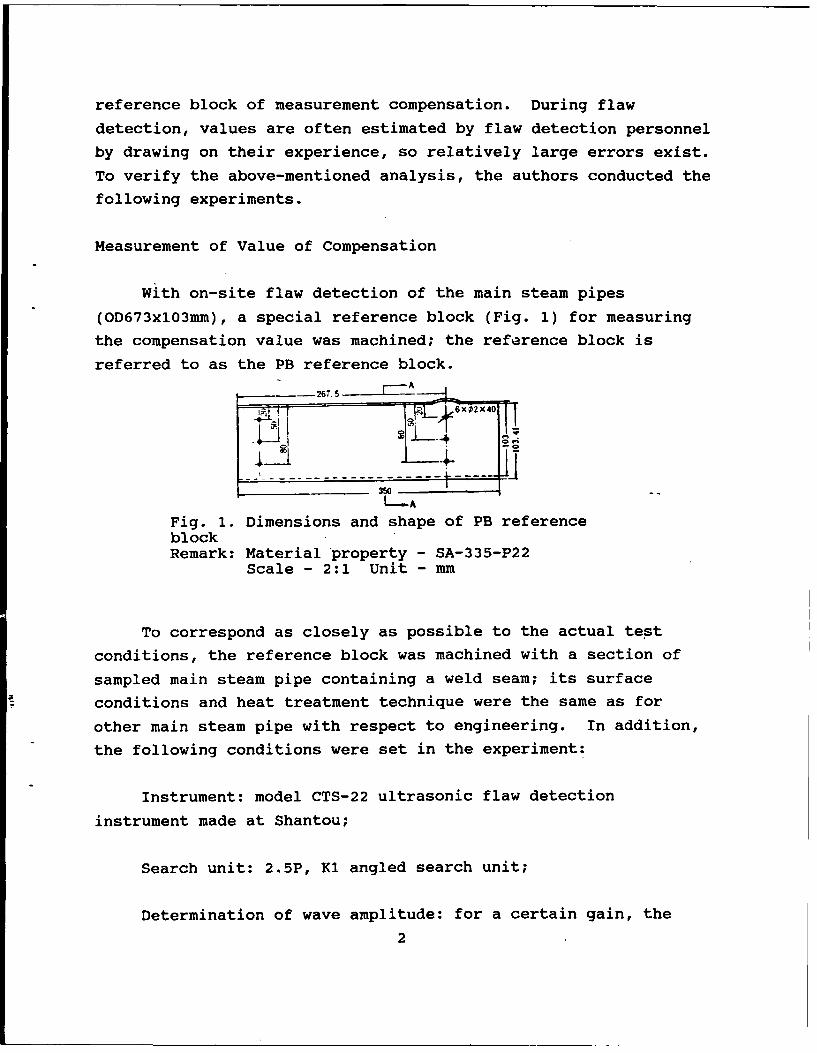
With on-site flaw detection of the main steam pipes
(OD673xl03mm), a special reference block (Fig. 1) for measuring
the compensation value was machined; the reference block is
referred to as the PB reference block.
267. 5
350
Fig. 1. Dimensions and shape of PB referenceblockRemark: Material property - SA-335-P22
Scale - 2:1 Unit - mm
To correspond as closely as possible to the actual test
conditions, the reference block was machined with a section of
sampled main steam pipe containing a weld seam; its surface
conditions and heat treatment technique were the same as for
other main steam pipe with respect to engineering. In addition,
the following conditions were set in the experiment:
Instrument: model CTS-22 ultrasonic flaw detection
instrument made at Shantou;
Search unit: 2.5P, Ki angled search unit;
Determination of wave amplitude: for a certain gain, the
2
wave amplitude was adjusted to the readout dB of the attenuator
at 80% of full graduation of the fluorescence; and
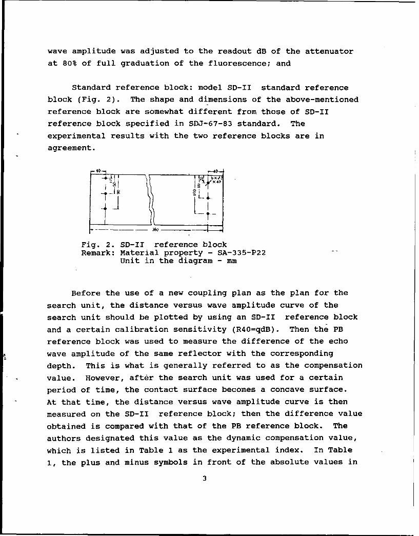
Standard reference block: model SD-II standard reference
block (Fig. 2). The shape and dimensions of the above-mentioned
reference block are somewhat different from those of SD-II
reference block specified in SDJ-67-83 standard. The
experimental results with the two reference blocks are in
agreement.
-40- - 0--
X Of
Fig. 2. SD-I1 reference blockRemark: Material property - SA-335-P22
Unit in the diagram - mm
Before the use of a new coupling plan as the plan for the
search unit, the distance versus wave amplitude curve of the
search unit should be plotted by using an SD-II reference block
and a certain calibration sensitivity (R40=qdB). Then the PB
reference block was used to measure the difference of the echo
wave amplitude of the same reflector with the corresponding
depth. This is what is generally referred to as the compensation
value. However, after the search unit was used for a certain
period of time, the contact surface becomes a concave surface.
At that time, the distance versus wave amplitude curve is then
measured on the SD-II reference block; then the difference value
obtained is compared with that of the PB reference block. The
authors designated this value as the dynamic compensation value,
which is listed in Table 1 as the experimental index. In Table
1, the plus and minus symbols in front of the absolute values in
3
the column of the dynamic compensation value represent,
respectively, the positive and the negative values of the
compensation value. The plus or minus symbols at the right upper
corner of the absolute value figure signify that the value is
slightly higher or slightly lower than the figure thus expressed.
For example, 6+ is slightly higher than 6; and 6- is slightly
lower than 6.
Analysis of Experimental Results
The following conclusions can be obtained from Table 1:
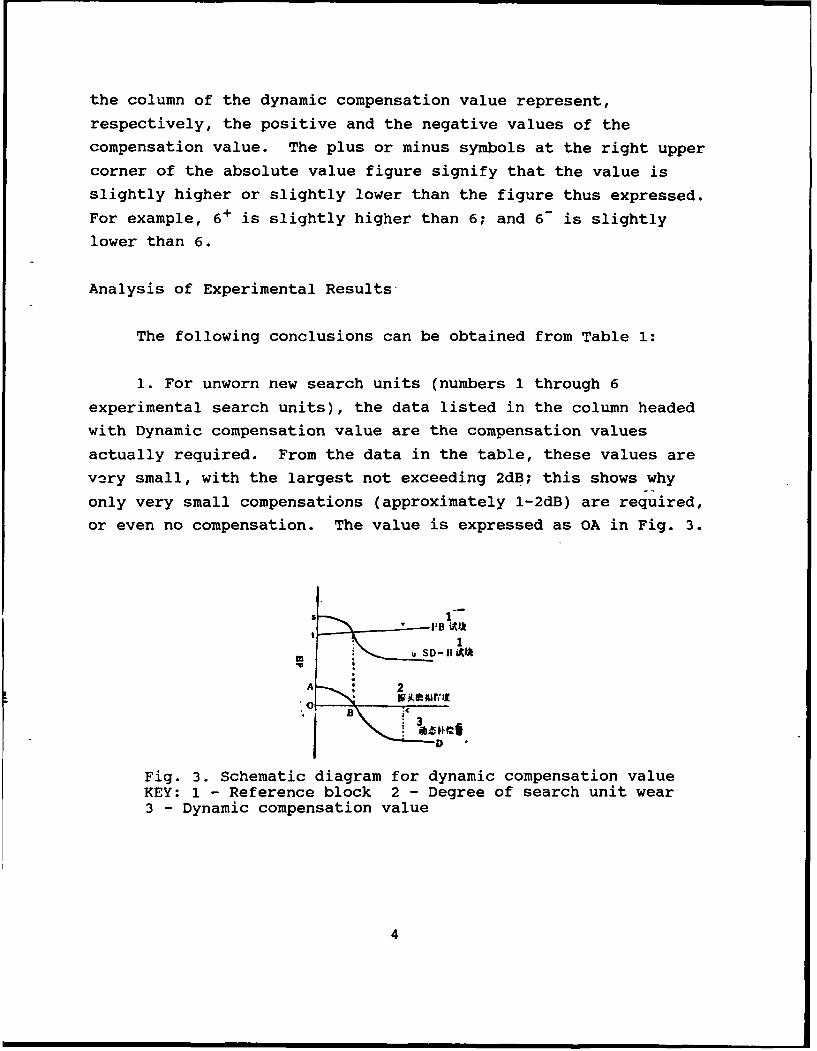
1. For unworn new search units (numbers 1 through 6
experimental search units), the data listed in the column headedwith Dynamic compensation value are the compensation values
actually required. From the data in the table, these values are
very small, with the largest not exceeding 2dB; this shows why
only very small compensations (approximately 1-2dB) are required,
or even no compensation. The value is expressed as OA in Fig. 3.
"--I'B AIJS 1
uSO- IIi0
A 2
*o B*1 DFig. 3. Schematic diagram for dynamic compensation valueKEY: 1 - Reference block 2 - Degree of search unit wear3 - Dynamic compensation value
4
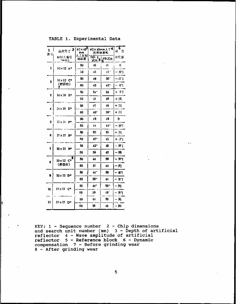
TABLE 1. Experimental Data
1 I - -2 02X403 2x4OmmXT 4
S1x16 B 50 148 5 +
I02 Ix12 C 50 49 -- - -i +________ ) 80 42 421 0+1i
3 14X 16 B 50 -- ISO 47 45 1+ 121
41 14 x16 E-' 0 4' J 46 J+ III80 40+] 39- J+ Ill
17 x17 Ps 50 49 49 1 0 080 44 44+ 1-101
6 17 x 17 Bs 0 W 52 51+ Ill
50 86 16-110x12 BO
___ 01 361421-1618 Ox 12 Cgs 5 4 0 1-i6i
(MOR)__ 80. 37 44 1~ -Ill9 I~x 12 DO 50': 44- 50 1--16"1
g I 01 , l + , I -,,-11 80 36+ 44 1- -
10 17 x17 C2 50 I 44- 50" 1-1718 39 8-i 1 +1
11 17x 17 D" 50_ _ _ 4 501 -16111 17x1 _ D" 80 38 46 181
KEY: 1 - Sequence number 2 - Chip dimensionsand search unit number (mm) 3 - Depth of artificialreflector 4 - Wave amplitude of artificialreflector 5 - Reference block 6 - Dynamiccompensation 7 - Before grinding wear8 - After grinding wear
5
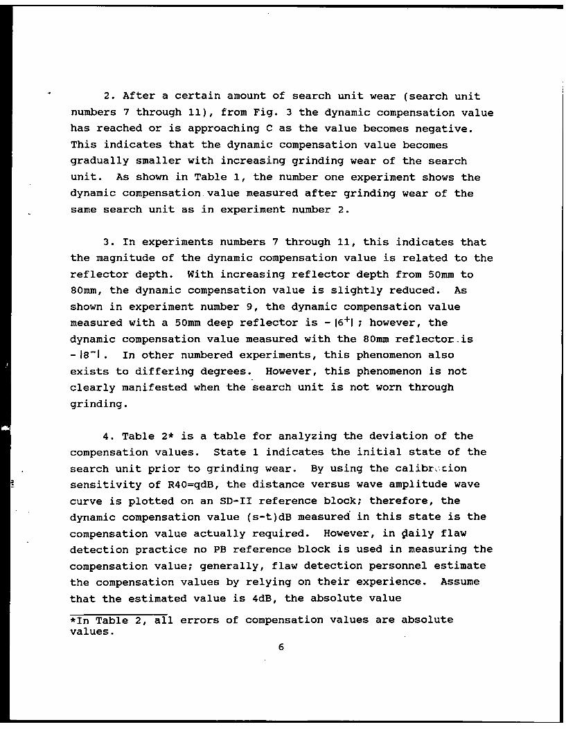
2. After a certain amount of search unit wear (search unit
numbers 7 through 11), from Fig. 3 the dynamic compensation value
has reached or is approaching C as the value becomes negative.
This indicates that the dynamic compensation value becomes
gradually smaller with increasing grinding wear of the search
unit. As shown in Table 1, the number one experiment shows the
dynamic compensation value measured after grinding wear of the
same search unit as in experiment number 2.
3. In experiments numbers 7 through 11, this indicates that
the magnitude of the dynamic compensation value is related to the
reflector depth. With increasing reflector depth from 50mm to
80mm, the dynamic compensation value is slightly reduced. As
shown in experiment number 9, the dynamic compensation value
measured with a 50mm deep reflector is -16+1 ; however, the
dynamic compensation value measured with the 80mm reflector-is
-18-1. In other numbered experiments, this phenomenon also
exists to differing degrees. However, this phenomenon is not
clearly manifested when the search unit is not worn through
grinding.
4. Table 2* is a table for analyzing the deviation of the
compensation values. State 1 indicates the initial state of the
search unit prior to grinding wear. By using the calibr .Cion
sensitivity of R40=qdB, the distance versus wave amplitude wave
curve is plotted on an SD-II reference block; therefore, the
dynamic compensation value (s-t)dB measured in this state is the
compensation value actually required. However, in Oaily flaw
detection practice no PB reference block is used in measuring the
compensation value; generally, flaw detection personnel estimate
the compensation values by relying on their experience. Assume
that the estimated value is 4dB, the absolute value
*In Table 2, all errors of compensation values are absolutevalues.
6
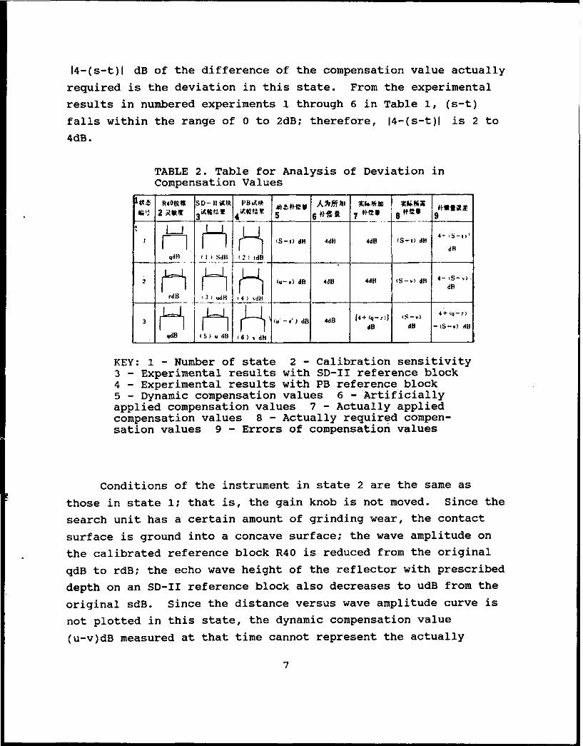
14-(s-t)l dB of the difference of the compensation value actually
required is the deviation in this state. From the experimental
results in numbered experiments 1 through 6 in Table 1, (s-t)
falls within the range of 0 to 2dB; therefore, 14-(s-t)l is 2 to
4dB.
TABLE 2. Table for Analysis of Deviation in
Compensation Values
10Z R4OWS SD- 11 Ak PBiUJ _-C A-M*t6h Ii Ni e3__M 4 _____ 5 9 7 8Ots 1
I ti S-t) dl 4dB 4dB S-t dH dRqdB 1 SM (2) tdB
2 1 I Jfi 1 I* f' (u-v)d 4dB 4dH (S-v) d) 4 - S - )I I dR
rdB 3 ) udB H 4 ) _d_
(u -v ) dB 4dB 14+ (q- r)) I"- ) 4+ (q-r)dB d8 -tS-v) dB
qdO (5) u dl 16) ' dli____
KEY: 1 - Number of state 2 - Calibration sensitivity3 - Experimental results with SD-II reference block4 - Experimental results with PB reference block5 - Dynamic compensation values 6 - Artificiallyapplied compensation values 7 - Actually appliedcompensation values 8 - Actually required compen-sation values 9 - Errors of compensation values
Conditions of the instrument in state 2 are the same as
those in state 1; that is, the gain knob is not moved. Since the
search unit has a certain amount of grinding wear, the contact
surface is ground into a concave surface; the wave amplitude on
the calibrated reference block R40 is reduced from the original
qdB to rdB; the echo wave height of the reflector with prescribed
depth on an SD-II reference block also decreases to udB from the
original sdB. Since the distance versus wave amplitude curve is
not plotted in this state, the dynamic compensation value
(u-v)dB measured at that time cannot represent the actually
7
required compensation value, which should be the difference
between the data point sdB on the distance versus wave amplitude
curve and vdB, the wave amplitude of a reflector with the same
depth on a PB reference block for the search unit in this state:
(s-v)dB. Assume that the artificial compensation value has not
been revised in time and is still 4dB; then the absolute value
14-(s-v)IdB of the difference between the two indicates the
deviation of the compensation value in that state. Since v>t,
14-(s-v)I> 14-(s-t)l . According to Table 1, the value of
14-(s-v)l is known to reach a value as high as 5 to 6dB.
After grinding wear of the search unit, the wave amplitude
may decrease to rdB from the original qdB when calibrated with an
R40 reference block; at that time, the wave height restored to
the qdB through the gain knob by the flaw detection personnel
because they considered that the distance versus wave amplitude
curve can be used only in the situation R40=qdB, thus forming
state 3 in the table. This calibration procedure raised
sensitivity by (q-r)dB; the reflector wave amplitude on the PB
reference block (corresponding to the actual workpiece) will not
be reduced because of the concave surface on the search unit.
Conversely the original tdB becomes vdB because of better
coupling. On adding 4dB of the artificial compensation, the
actually added compensation value is [4+(q-r)]dB. Then, can
(s-v') be used to indicate directly the required compensation
value? Since the instrument state expressed by state 3 is not
the same as state 1; only in the situation of the same instrument
state can these two be deducted directly in order to obtain the
compensation value. Therefore (s-v') cannot represent the
actually required compensation value in state 3. Since the
instrument state of state 2 is the same as that of state 1, and
the search unit state is the same as state 3, the required
compensation value (s-v) in state 2 is the required compensation
value in state 3. Thus, the obtained deviation of compensation
value in state 3 is 14+(q-r)-(s-v)l dB, which is actually the
8
summation of the three-deviation difference; the value is
relatively appregiable.
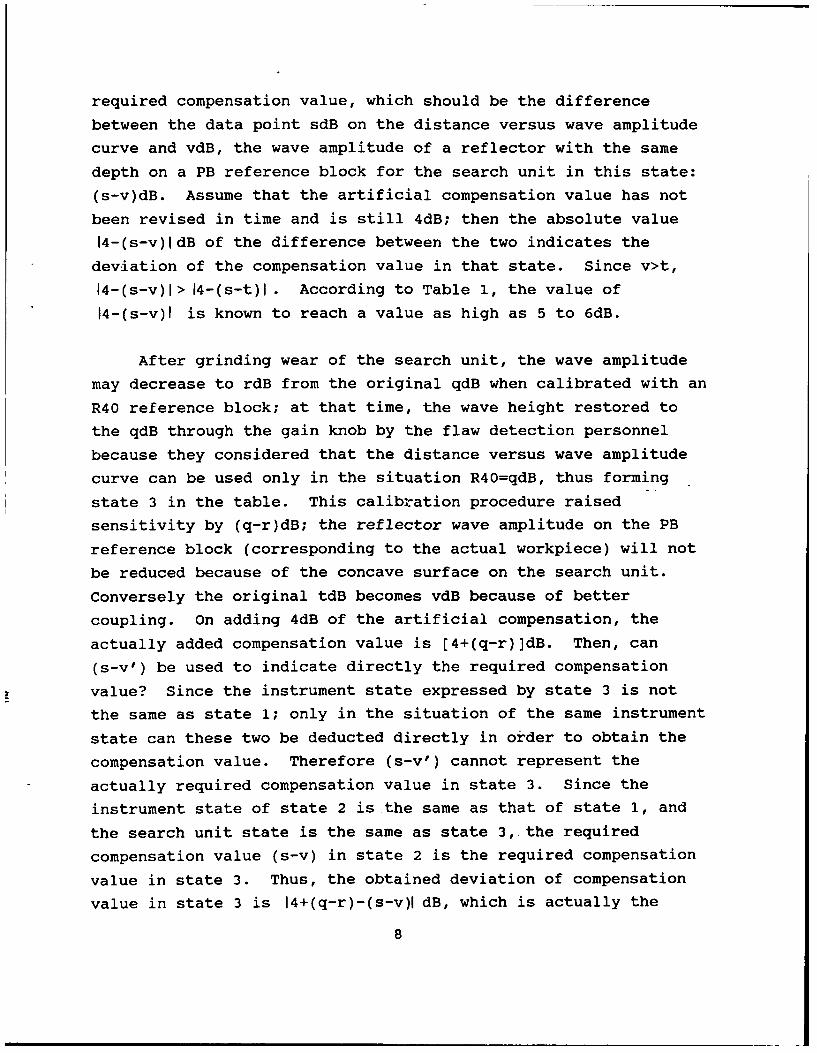
From data in Table 1 and from Fig. 3, it is apparent that
the echo wave amplitude does not increase appreciably although
the coupling condition on the PB reference block is improved
after wearing of the coupling surface of the search unit into a
curved surface. This is because of the diffusion of sound beams
in the coupling state of the curved state; refer to Fig. 4 for
its principle.1WYL
MFig. 4. Schematic diagram of sound beamsscattered by the curved surface of thecoupling search unitKEY: 1 - Organic glass 2 - Steel
Discussion
The above-mentioned discussion explains that measurements
should be made of the compensation value before a search unit is
used, and the original data should be provided for calculating
the search unit compensation value after grinding wear. A
certain deviation exists in artificial estimates; for instance,
in the example mentioned at the beginning of this article, the
artificial estimate is 4dB, but the actually required
compensation value is only between 0 and 2dB.
Both Table I and Fig. 3 sufficiently explain that the
compensation value becomes smaller with steady deepening of the
extent of search unit grinding wear. When a certain amount of
9
grinding wear is attained, both the dynamic compensation value
and the compensation value reach minima after passing through
point C as shown in Fig. 3. This value does not vary with
continual grinding wear of the search unit.
To eliminate the deviation of the (q-r) item in state 3,
effective measures should be taken to ensure the instrument state
(primarily as the gain) to maintain constancy throughout the flaw
detection procedure and during the next flaw detection session.
Only by ensuring this point can no calibration be required for
sensitivity by using R40 reference blocks. In the grinding wear
process of flaw detection for a Q search unit at the beginning of
this article, engineering personnel steadily calibrate by using
R40 reference blocks, so the deviation of the (q-r)-th order
exists; this is equivalent to determining the flaw to a higher
value by [4+q-r)-(s-v)]dB. According to preliminary experiments,
(q-r) may reach a value in the vicinity of 5dB.
The authors are grateful for assistance given in the
experiments by the relevant departments of the Second Engineering
Company of Electric Construction, Anhui.
REFERENCES
1. Technical Norms of Construction and Acceptance of PowerGeneration Projects (Part of Ultrasonic Inspection ofPipe Welds), SDJ 67-83, Water Conservation and PowerGeneration House, 1984, 1, 13.
2. Chaoshengbo Tanshang [Ultrasonic Flaw Detection], PowerGeneration Industry Publishing House, 1980, 11.
3, Chaoshengbo Tanshang Fa [Ultrasonic Method of FlawDetection], Gwangdung Publishing House of Science andTechnology, 1981, 6.
10
YINGHAN WUSUN JIANCE CIHUI [English-Chinese Dictionary of
Nondestructive Testing Terms]
As a reference book, this dictionary is a collection of
about 18,000 terms and abbreviations; most of the terms are basic
terms and special terms frequently used in English books and
journals on nondestructive testing. The technical terms are in
the following fields: ultrasonids, rays, electromagnetism, eddy
current, permeability, sound emission, stress, laser, infrared
rays, and microwaves, among other fields. In addition, the
dictionary also includes technical terms related to the following
professions involved in the nondestructive testing specialty:
physics, electronics, computer science, machines, and metallurgy,
among others. This dictionary was compiled by the Nondestructive
Testing Institute of the China Society of Mechanical Engineering;
the dictionary can serve as a reference book for scientific
researchers in the nondestructive testing specialty, and the
field-related engineers, technicians, technical translators, as
well as teachers and students of the corresponding universities
and professional colleges. The dictionary was scheduled to be
published in June 1989.
11
CONTROL OF K VALUE FOR RADIOGRAPHIC INSPECTION OF WELDED JOINTS
Li Yan, Wuxi Boiler Works
The author discusses the significance of controlling the
penetrating thickness ratio K and the maximum thickness ratio
Kmax in the radiographic inspection of welded joints, referring
to the new national standard GB 3323-87 that has been published.
Taking typical radiographic inspections as examples, the paper
presents particular methods for controlling the K value and the
Kmax value, as well as practical applications.
I. Introduction
In the newest revised international standard GB3323-87,
"Radiography and Quality Classification of Butt Joints of Steel
Melt Welding," control requirements on the thickness ratio K for
radiographic inspection are mentioned. In similar standards
abroad, such as BS 2600/1-73, ISO R1106-72, and JIS Z3104-74,
similar requirements are also mentioned, only with different
formulation approach. The requirements of the K value are listed
in two international standards; this indicates that China's
radiographic technique of flaw detection has been raised to a new
quantitative level. However, a correct understanding is
necessary for the meaning and control of the K value; otherwise,
confusion or misdirection will be present in work practice.
II. Definition of the K Value
12
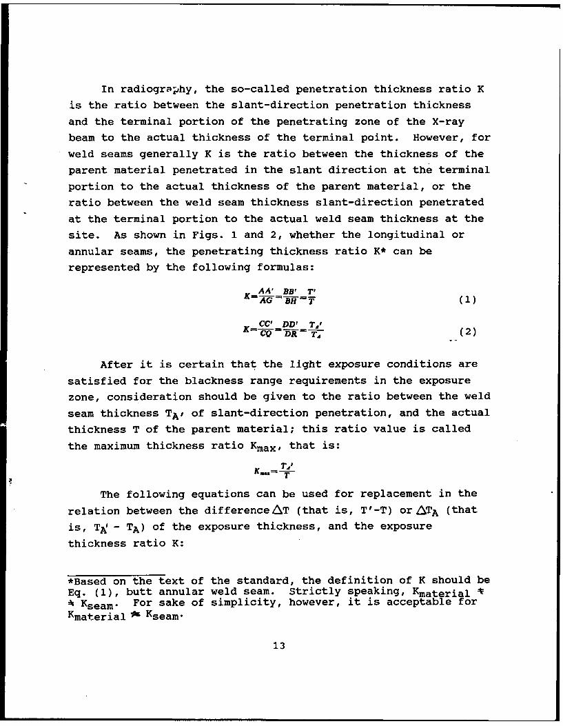
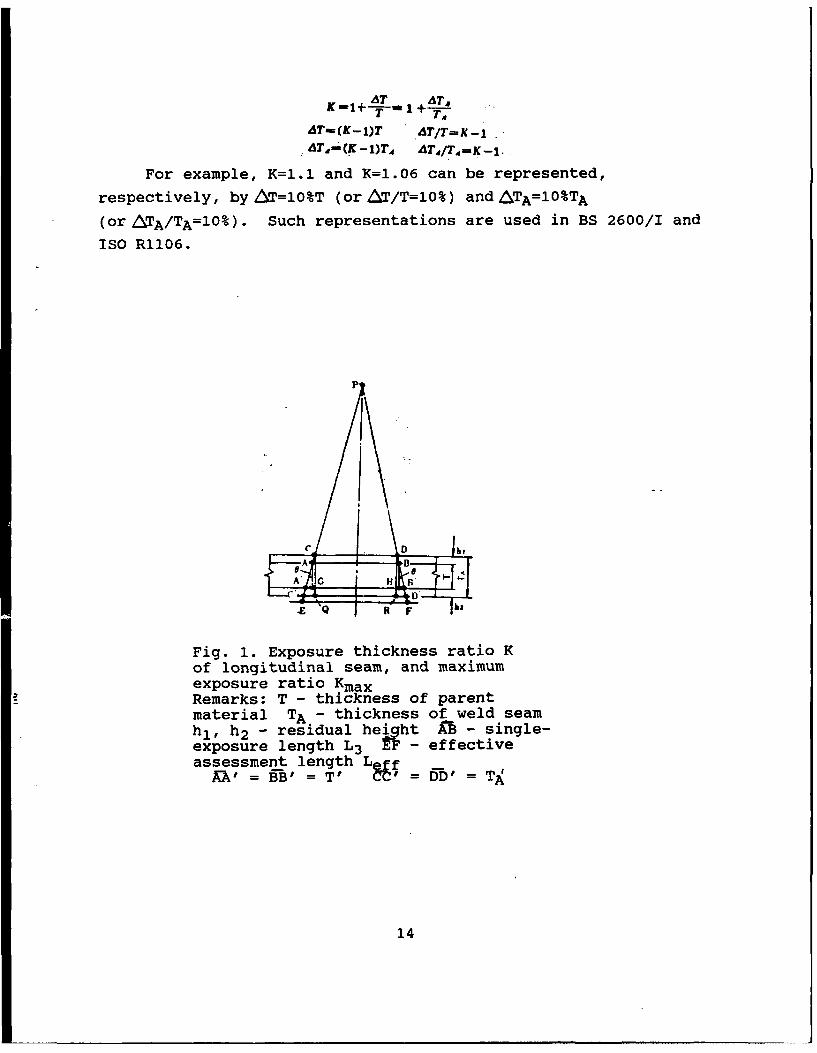
In radiography, the so-called penetration thickness ratio K
is the ratio between the slant-direction penetration thickness
and the terminal portion of the penetrating zone of the X-ray
beam to the actual thickness of the terminal point. However, for
weld seams generally K is the ratio between the thickness of the
parent material penetrated in the slant direction at the terminal
portion to the actual thickness of the parent material, or the
ratio between the weld seam thickness slant-direction penetrated
at the terminal portion to the actual weld seam thickness at the
site. As shown in Figs. 1 and 2, whether the longitudinal or
annular seams, the penetrating thickness ratio K* can be
represented by the following formulas:
K AA' BB' T'G W-ff (1)
K CC' DD' T,'=CQ DR T (2)
After it is certain that the light exposure conditions are
satisfied for the blackness range requirements in the exposure
zone, consideration should be given to the ratio between the weld
seam thickness TAP of slant-direction penetration, and the actual
thickness T of the parent material; this ratio value is called
the maximum thickness ratio Kmax, that is:
T'?
The following equations can be used for replacement in the
relation between the difference AT (that is, T'-T) or/ATA (that
is, TA! - TA) of the exposure thickness, and the exposure
thickness ratio K:
*Based on the text of the standard, the definition of K should beEq. (1), butt annular weld seam. Strictly speaking, Kmaterial V: Kseam. For sake of simplicity, however, it is acceptable forKmaterial w Kseam-
13
AT T
AT-(K-1)T ATI/T-K-1-AT, -KI)T4 AT4 /T4 =K -1.
For example, K=1.1 and K=l.06 can be represented,
respectively, by Tf=10%T (or AT/T=10%) and ATA=10%TA
(or ATA/TA=10%). Such representations are used in BS 2600/I and
ISO R1106.
p
eD h,
AAG
Z Q R F k
Fig. 1. Exposure thickness ratio Kof longitudinal seam, and maximumexposure ratio KmaxRemarks: T - thickness of parentmaterial TA - thickness of weld seamhl, h2 - residual heght A - single-exposure length L3 - effectiveassessment length L f -
9BB'? = TV C = DD' =-T1
14
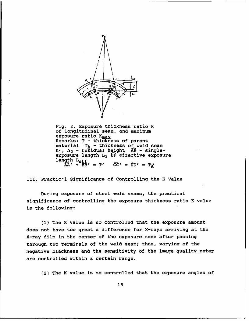
Fig. 2. Exposure thickness ratio Kof longitudinal seam, and maximumexposure ratio KmaxRemarks: T - thickness of parentmaterial TA - thickness of weld seamhl, h2 - residual height M - single-exposure length L3 a effective exposurelength Lefifi
A, =e = T' C' = =T
III. Practic-l Significance of Controlling the K Value
During exposure of steel weld seams, the practical
significance of controlling the exposure thickness ratio K value
is the following:
(1) The K value is so controlled that the exposure amount
does not have too great a difference for X-rays arriving at the
X-ray film in the center of the exposure zone after passing
through two terminals of the weld seam; thus, varying of the
negative blackness and the sensitivity of the image quality meter
are controlled within a certain range.
(2) The K value is so controlled that the exposure angles of
15
the lateral-direction crack type defects along the wall thickness
direction of two terminals of the exposure zone are not too much
different, thus enhancing the detection rate of the hazardous
defects like cracks.
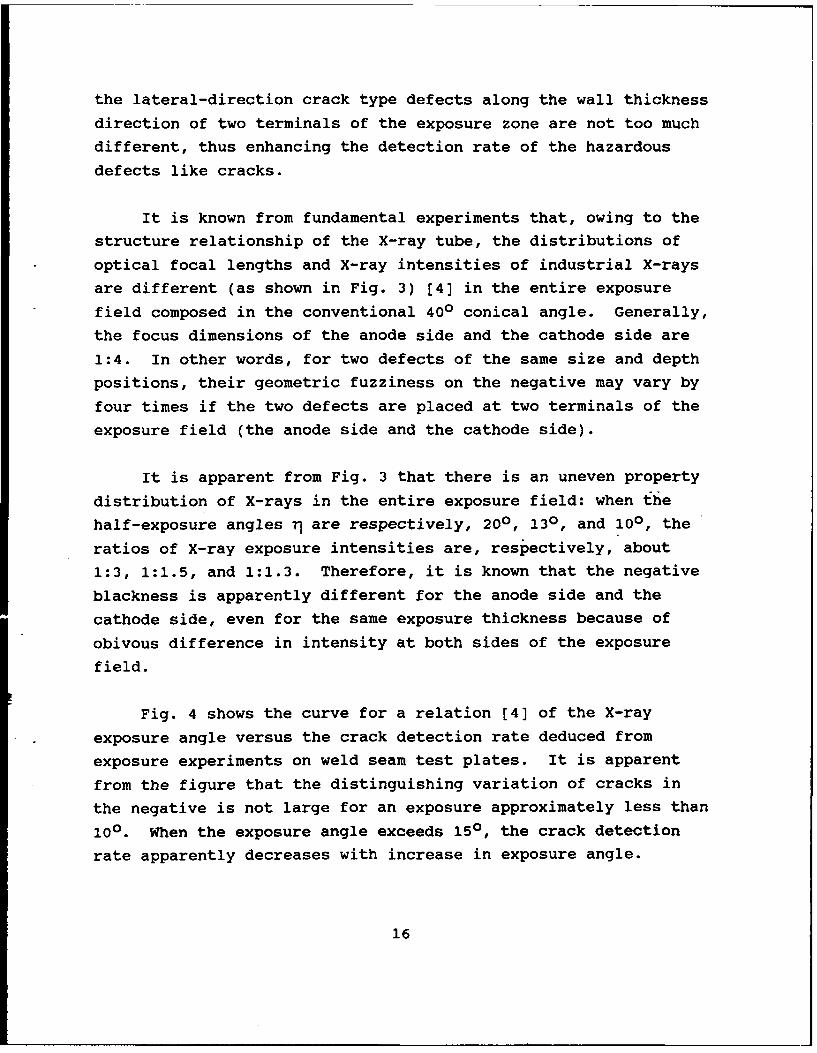
It is known from fundamental experiments that, owing to the
structure relationship of the X-ray tube, the distributions of
optical focal lengths and X-ray intensities of industrial X-rays
are different (as shown in Fig. 3) [4] in the entire exposure
field composed in the conventional 400 conical angle. Generally,
the focus dimensions of the anode side and the cathode side are
1:4. In other words, for two defects of the same size and depth
positions, their geometric fuzziness on the negative may vary by
four times if the two defects are placed at two terminals of the
exposure field (the anode side and the cathode side).
It is apparent from Fig. 3 that there is an uneven property
distribution of X-rays in the entire exposure field: when the
half-exposure angles rj are respectively, 200, 130, and 100, the
ratios of X-ray exposure intensities are, respectively, about
1:3, 1:1.5, and 1:1.3. Therefore, it is known that the negative
blackness is apparently different for the anode side and the
cathode side, even for the same exposure thickness because of
obivous difference in intensity at both sides of the exposure
field.
Fig. 4 shows the curve for a relation [4] of the X-ray
exposure angle versus the crack detection rate deduced from
exposure experiments on weld seam test plates. It is apparent
from the figure that the distinguishing variation of cracks in
the negative is not large for an exposure approximately less than
100. When the exposure angle exceeds 150, the crack detection
rate apparently decreases with increase in exposure angle.
16
2 3
0* • * 10 0 * A ohs
W207 75
6*. *•momi
S10. 0 . 0
3:1
Fig. 3. Variations of intensity distribution,focus dimension, and shape within the X-rayexposure fieldKEY: 1 - Cathode 2 - X-ray tube 3 - Anode4 - Angle 5 - Intensities 6 - Cathode side7 - Anode side 8 - Intensity ratios of X-raysat both sides of half-radiation angle
Therefore, the entire exposure field cannot be used for the
exposure of a weld seam, but only for utilizing, as much as
possible, the middle portion (that is, the range of rl=±I4 0 ) of
the exposure field for exposure. Physically, the control of the
K value amounts to controlling the exposure ratio thickness;
actually, this is the control of the dimension of the effective
exposure field, the control of the ratio between the crack
exposure angle and the X-ray intensity; therefore, this relates
to the control of the effective exposure length required for
sensitivity of the image quality meter in order to satisfy a
certain degree of blackness.
17
-.' - 3' -" IO O" 10" " 30" 40"
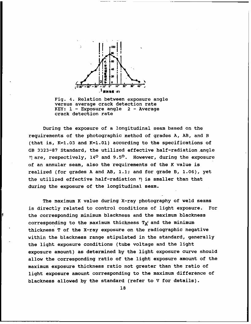
Fig. 4. Relation between exposure angleversus average crack detection rateKEY: 1 - Exposure angle 2 - Averagecrack detection rate
During the exposure of a longitudinal seam based on the
requirements of the photographic method of grades A, AB, and B
(that is, K=1.03 and K=1.01) according to the specifications of
GB 3323-87 Standard, the utilized effective half-radiation angle
'9 are, respectively, 140 and 9.50. However, during the exposure
of an annular seam, also the requirements of the K value is
realized (for grades A and AB, 1.1; and for grade B, 1.06), yet
the utilized effective half-radiation r) is smaller than thatduring the exposure of the longitudinal seam.
The maximum K value during X-ray photography of weld seams
is directly related to control conditions of light exposure. For
the corresponding minimum blackness and the maximum blackness
corresponding to the maximum thickness TA and the minimum
thickness T of the X-ray exposure on the radiographic negative
within the blackness range stipulated in the standard, generally
the light exposure conditions (tube voltage and the light
exposure amount) as determined by the light exposure curve should
allow the corresponding ratio of the light exposure amount of the
maximum exposure thickness ratio not greater than the ratio of
light exposure amount corresponding to the maximum difference of
blackness allowed by the standard (refer to V for details).
18
IV. Single-Exposure Length Related to the K Value
When section by section light exposure is adopted for weld
seams, the weld seam length exposed in each light exposure is
called the single-exposure length L3 , whose projection length
onto the radiographic negative is called the effective assessment
length Leff. However, determination of L3 should satisfy the
requirements on exposure thickness ratio K. Therefore, there is
a certain limiting relation between L3 and the distance L, from
the radiation source to the workpiece surface.
1. Requirements on the K value in longitudinal seam exposure
and single-exposure length
The requirements on the K value originate from the
requirements on lateral-direction crack detection angle (or the
maximum distortion angle of the image) 0 in the terminal portion
of the exposure zone. To meet different requirements of the
GB 3323-87 Standard on the longitudinal seam exposure thickness
ratio K value to adapt to different grades of image quality, L1
and L3 should be determined from the following:
for grade Afor grade AB, when LI 2L3 , e5140 , K51.03
for grade B, when L123L 3 , 059.5O, K 5.01
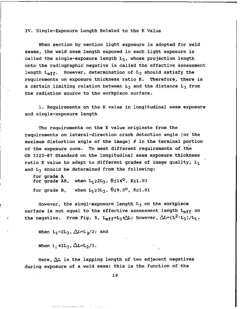
However, the singl-exposure length L3 on the workpiece
surface is not equal to the effective assessment length Leff on
the negative. From Fig. 5, Leff=L3 ,1L; however, AL=(L2 "L3 )/LI.
When L1=2L 3 , AL=L 2/2; and
When I =3L 3 , AL=L2/3.
Here, AL is the lapping length of two adjacent negatives
during exposure of a weld seam; this is the function of the
19
workpiece thickness.
Fig. 5. Relation between L3 and L1 versuse and K in longitudinal seam exposure method
2. Requirements on the K value and single-exposure length in
annular seam exposure
When exposure of an annular seam is carried out, generally
the requirements on the K value in other exposure modes cannot be
the same as those on the K value for butting a longitudinal seam
besides the adoption of internal exposure center method by
placing the radiation source at the position of the circle's
center, or the internal exposure eccentric method with a
radiation source not deviating far from the circle's center.
Otherwise, the welding seam length will be very short for each
exposure, and the working efficiency of radiography will be
lowered. Therefore, the GB3323-87 Standard, the BS 2600
Standard, and the ISO R1106 Standard only impose requirements of
1.1 (ordinary grade and relatively higher grade) and 1.06 (high
grade) for the K value on exposure of annular seams. In other
words, control of the lateral-direction crack detection angle of
annular weld seams, or image distortion angle will be relaxed to
a certain extent than in the case of a longitudinal seam. In the
following, a discussion is made on the external exposure method
and the dual-wall single-image method, which are used as
20
examples; these methods are mostly used with the most
representative feature.
a. External exposure method (the exposure method with the
radiation source at the outside and the film inside)
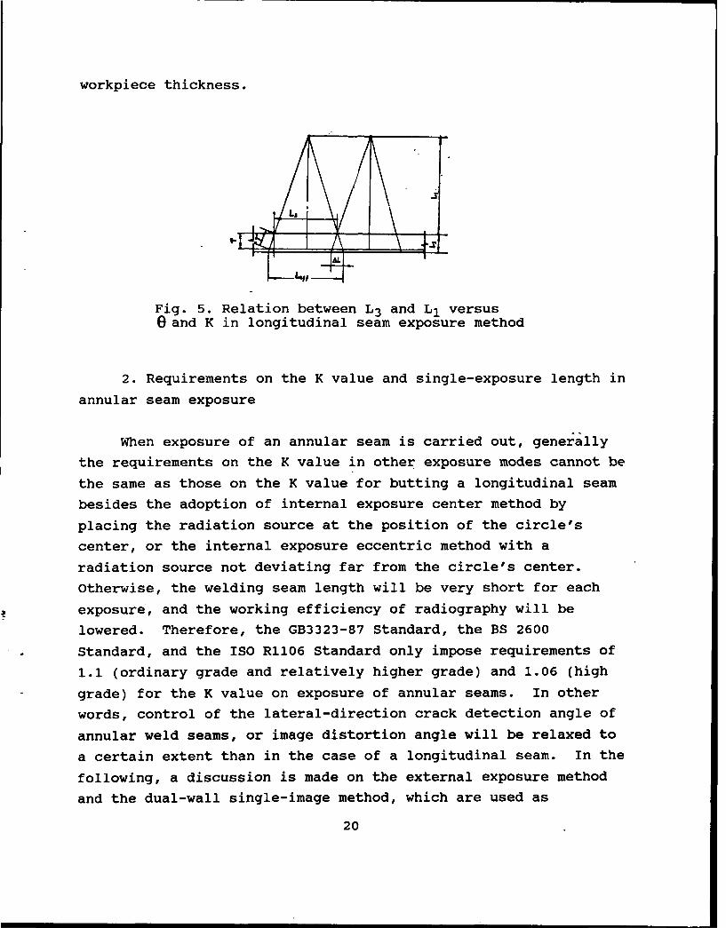
To determine the single-exposure length L3 of the annular
seam, the minimum light exposure times N to satisfy the
requirements of a certain K value for 100% exposure of the entire
ring of an annular weld seam can be first determined, as shown in
Fig. 6.
AB--3 CD=L' A0'=L.,, iA,=T, A=--
Fig. 6. Determination of the single-exposurelength L3 at the radiation source site in theexternal exposure method for weld seams
a C
In this equation, a=e9-l.
InLAOAA', we obtain the following from the theorem ofRI+T"-r'cosines : S= R'
RRT
I r T(K'-1
When K=I.l1, (9 o-,"!+
liLi
When K=.06, ~ N=182T+
1.1cosine cs 'O _2T 1When K=I. 06, 0cs1 .06TD
21.
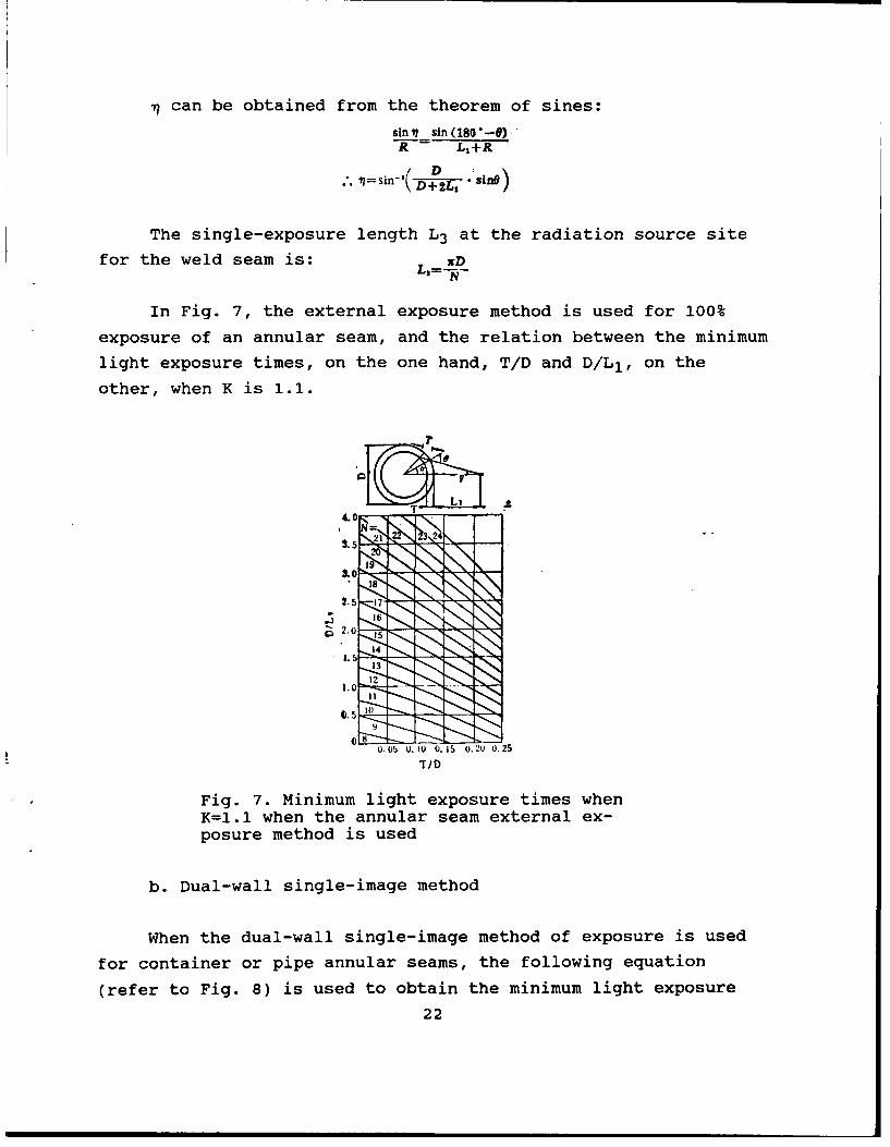
can be obtained from the theorem of sines:sinv sin (180 *-)
R-- LI+R
7 T= sin-'( D2L •sinO)• D+2L1
The single-exposure length L3 at the radiation source site
for the weld seam is: xD
In Fig. 7, the external exposure method is used for 100%
exposure of an annular seam, and the relation between the minimum
light exposure times, on the one hand, T/D and D/L1 , on the
other, when K is 1.1.
T L
$.5 -
4.0
. 0
8;
0. 02 0. 10 0.715 0. NU 25
TID
Fig. 7. minimum light exposure times whenK=1.1 when the annular seam external ex-posure method is used
b. Dual-wall single-image method
When the dual-wall single-image method of exposure is used
for container or pipe annular seams, the following equation
(refer to Fig. 8) is used to obtain the minimum light exposure
22
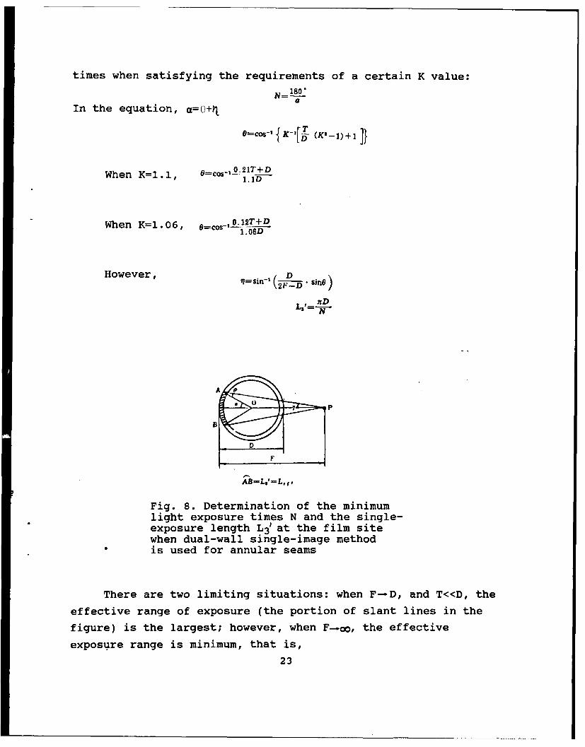
times when satisfying the requirements of a certain K value:
aIn the equation, a=0+11
O=¢=- 1 K-2[1 (K,-1)+1 J}
When K=l1l, --c-O 21T+D• 1.1D
When K=1.06, O cs ,0. 12T+D1. 06D
However, -sin-' D sjnO)
2FD
AD
0 0
0,..~ , . .E ,i ,7D
Fig. 8. Determination of the minimumlight exposure times N and the single-exposure length L3' at the film sitewhen dual-wall single-image methodis used for annular seams
There are two limiting situations: when F-D, and T<<D, the
effective range of exposure (the portion of slant lines in the
figure) is the largest; however, when F-.o0, the effective
exposure range is minimum, that is,
23

In the dual-wall single-image method for annular seams,
therefore, the minimum and maximum number of films photographed
can be represented by the following equations:90"
180
If consideration is given to the fact that the exposure
angle 0 is 150 for lateral-direction cracks along the wall
thickness direction at both terminals of the exposure zone, then
N12 90"15"
15.
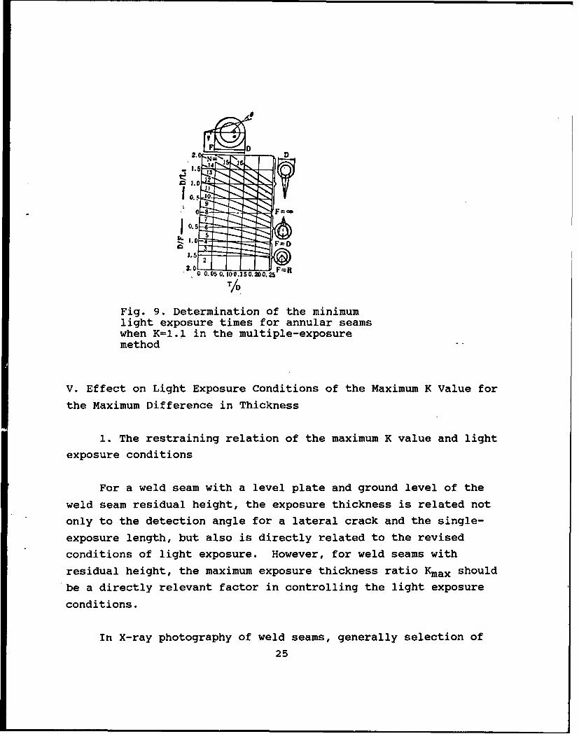
Fig. 9 shows the relation between the minimum light exposure
times of weld seams when K=1.1, on the one hand, and T/D, D/E,
and D/F, on the other hand, in various exposure methods. In the
figure, only the condition D/F<1.0 is given for the dual-wall
single-image method. From the figure, when D/L1 or D/F is
constant when applying the external exposure method and the
dual-wall single-wall exposure method, the number of photographic
films that satisfy K=1.1 is gradually increased with increase in
T/D by exceeding a certain range. In addition, the relative
speed of increase in the number of photographic films in the
external exposure method is relatively high. Besides, when T/D
is a constant, the number of photographic films is increased
under the external exposure method when the increase in D/L1
exceeds a certain range; however, for the dual-wall single-image
method, the number of photographic films is decreased if a
certain range is exceeded when there is an increase in D/F.
24
F DD
2.0N
S 14
1 2 "2
10.5
. 0 0.05 0. 00.150.00.25F =
Fig. 9. Determination of the minimumlight exposure times for annular seamswhen K=I.1 in the multiple-exposuremethod
V. Effect on Light Exposure Conditions of the Maximum K Value for
the Maximum Difference in Thickness
1. The restraining relation of the maximum K value and light
exposure conditions
For a weld seam with a level plate and ground level of the
weld seam residual height, the exposure thickness is related not
only to the detection angle for a lateral crack and the single-
exposure length, but also is directly related to the revised
conditions of light exposure. However, for weld seams with
residual height, the maximum exposure thickness ratio Kmax should
be a directly relevant factor in controlling the light exposure
conditions.
In X-ray photography of weld seams, generally selection of
25
light exposure conditions should enable X-rays to fall within the
negative exposure range; the blackness in the negative after
penetrating with the maximum exposure thickness (both terminals
are weld seams) and the minimum exposure thickness (the heat-
affected zone in the vicinity of the center of the examined zone)
fall within the range stipulated by the standard (such as the
blackness range between 1.2 and 3.5 as specified in GB 3323-87).
Moreover, it is required that the photographic sensitivity within
the effective exposure range meets the specified index.
Therefore, the maximum thickness ratio Kmax of exposure should be
used to determine the tube voltage and light exposure meeting the
requirements of negative blackness and sensitivity of the image
quality meter. On this aspect, relatively satisfactory results
can be realized by using the light exposure curve and film
property curve plotted from a series of light exposure
experiments.
Generally, it is customary to find the correct exposing
light conditions from a figure of the light exposure curve for
weld seam thickness at the exposure zone center; in so doing,
frequently no negative quality meeting the requirements is
realized. Therefore, the tube voltage and light exposure should
be correctly selected based on the thickness ratio and the
blackness in the exposure zone, sensitivity of light quality
meter, and clarity.
Generally, technical terms of the maximum thickness
difference are applied. Conversion can be carried out by using
the following equations for the maximum thickness ratio Kmax and
the maximum thickness difference/ATmax (refer to Figs. 1 and 2
for the meaning of the symbols in the equations):
uX7 AT.-T,'-T
O r , T-2
26
2. Maximum thickness difference and the feasible tube
voltage
In principle, the tube voltage should be so selected for
exposure of welded joints with given thickness difference of
exposure, the ratio of light exposure (b') of the film after the
X-rays penetrate the minimum thickness and the maximum thickness
within the effective range is not greater than the ratio (VI)
[1, 2] of the corresponding light exposure in the stipulated
range of blackness obtained when using the film.
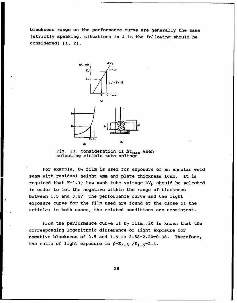
As shown in Fig. 10, if the stipulated range of blackness is
D1 and D2, and the condition of blackness of the light exposure
curve is 'D1 , then for a weld seam with thickness T for the
exposure plate and TA equal to the plate thickness adding the
residual height, then Et' E,=# .
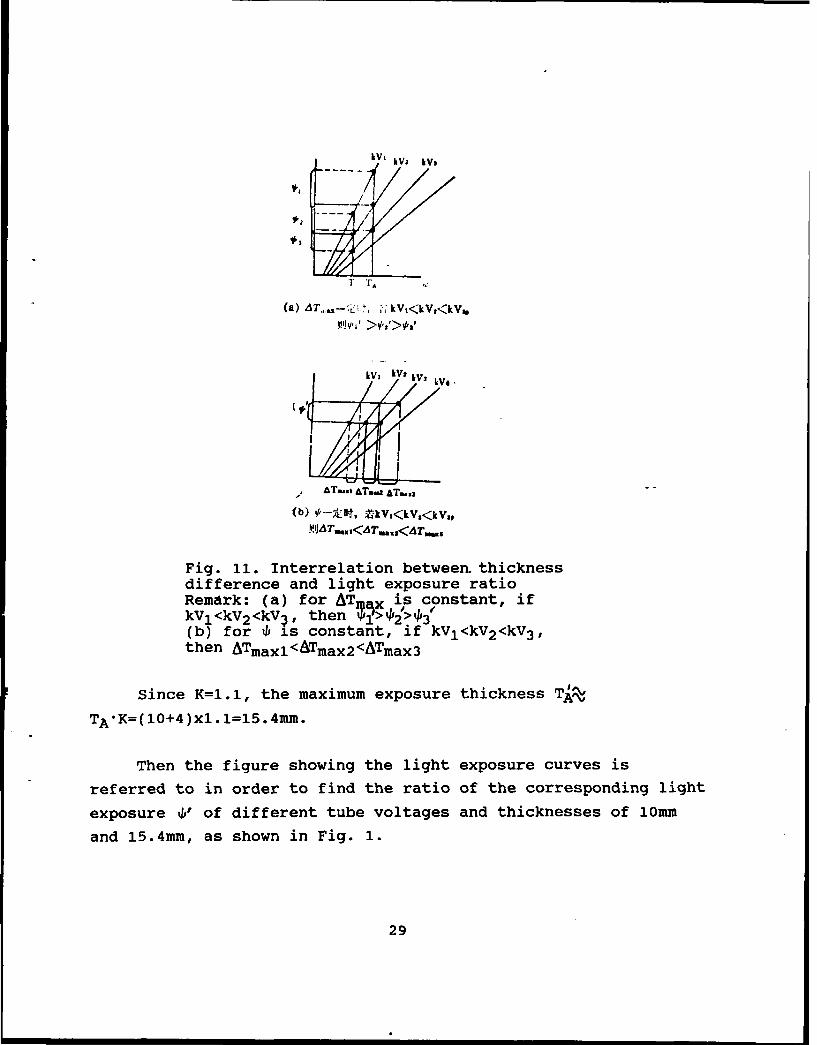
With exposure of a thin-plate weld seam, to control the
blackness of the parent material zone and the weld seam-zone
within the standard stipulated range, the relation of 4,'>4 should
be noted when selecting the feasible tube voltage. Because from
the light exposure curve in the figure, the slant lines
representing the lower tube voltage have the greater inclination;
therefore, with the same thickness difference for the exposure
the ratio of light exposure received by the film with lower tube
voltage should be greater than the ratio of light exposure
received by the film for higher tube voltage, as shown in
Fig. 11. However, the tube voltage should not be selected too
high; otherwise, although the range of black on the negative can
meet the requirements, yet the sensitivity of the image quality
meter may possibly not attain the requirements. In the best
case, the ratio of light exposure + generated after the selected
tube voltage penetrating the maximum thickness difference, and
the ratio of light exposure p corresponding to the stipulated
27
blackness range on the performance curve are generally the same
(strictly speaking, situations in 4 in the following should be
considered) [1, 2].
mA min RiVp
El. TA'=TA K
T 'CA' MM
(a)
D2
E4'
Fig. 10. Consideration of ATmax whenselecting visible tube voltage
For example, D7 film is used for exposure of an annular weld
seam with residual height 4mm and plate thickness 10mm. It is
required that K=1.1; how much tube voltage kVp should be selected
in order to let the negative within the range of blackness
between 1.5 and 3.5? The performance curve and the light
exposure curve for the film used are found at the close of the.
article; in both cases, the related conditions are consistent.
From the performance curve of D7 film, it is known that the
corresponding logarithmic difference of light exposure for
negative blackness of 3.5 and 1.5 is 2.58-2.20=0.38. Therefore,
the ratio of light exposure is O=E 3 .5 /EI. 5=2.4.
28
V.'I
kV lV ,kV*
'VIV,
AT...,AT..zAT...
IPJAT. 1 1 AT,,<AT.
Fig. 11. Interrelation between- thicknessdifference and light exposure ratioRemark: (a) for AT axis constant, ifkVj <kV2 <kV4, then j>,, 1#(b) for %P is constant, if kVl<kV2<kV3 ,then ATmaxl<ATmax2<ATmax3
Since K=1.1, the maximum exposure thickness TA-
TA*K=(1O+4)X1.1=15.4MM.
Then the figure showing the light exposure curves is
referred to in order to find the ratio of the corresponding light
exposure V" of different tube voltages and thicknesses of 10mm
and 15.4mm, as shown in Fig. 1.
29
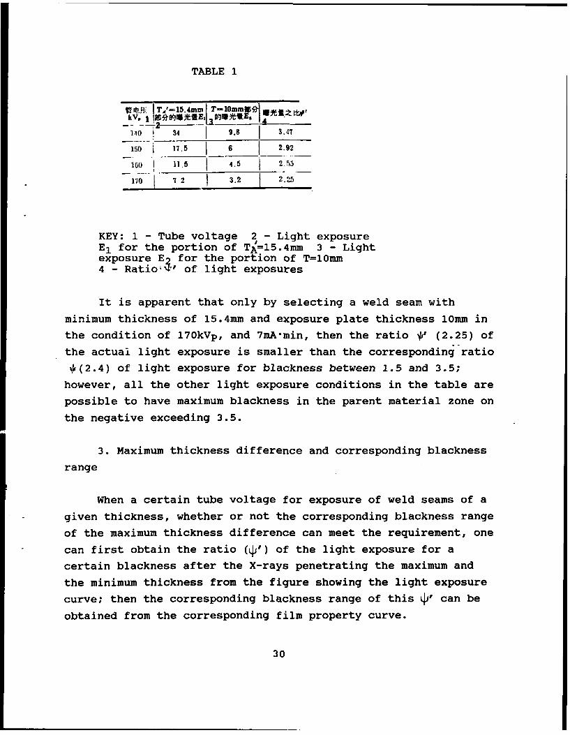
TABLE 1
T,-5.m T-1Ornrni
140 34 9.8 3.47
150 17.5 6 2.92
160 1 11.5 4.5 2.53
170 7 2 3.2 22
KEY: 1 - Tube voltage 2 - Light exposureE1 for the portion of TA=15.4mm 3 - Lightexposure E2 for the portion of T=10mm4 - Ratio"' of light exposures
It is apparent that only by selecting a weld seam with
minimum thickness of 15.4mm and exposure plate thickness 10mm in
the condition of 170kVp, and 7mA-min, then the ratio *' (2.25) of
the actual light exposure is smaller than the corresponding ratio
4(2.4) of light exposure for blackness between 1.5 and 3.5;
however, all the other light exposure conditions in the table are
possible to have maximum blackness in the parent material zone on
the negative exceeding 3.5.
3. Maximum thickness difference and corresponding blackness
range
When a certain tube voltage for exposure of weld seams of a
given thickness, whether or not the corresponding blackness range
of the maximum thickness difference can meet the requirement, one
can first obtain the ratio (d') of the light exposure for a
certain blackness after the X-rays penetrating the maximum and
the minimum thickness from the figure showing the light exposure
curve; then the corresponding blackness range of this q' can beobtained from the corresponding film property curve.
30
For example, by using D7 film and 200kVp for exposure of an
annular weld seam with a total residual height of 4mm with 28mm
as the parent material thickness, it is required that K=1.1.
Whether or not the blackness range on the negative can meet the
requirements of 1.5 to 3.5 is a question.
In this example, by referring to light exposure curve, the
maximum exposure thickness Tgz(28+4)xl.l=35.2mm. From the light
exposure curve, by using 200kVp for the exposure of 35.2mm
thickness, obtaining 1.5 as the blackness, the light exposure
amount is 30mA-min; however, the light exposure amount is
13.5mA'min for exposure of 28mm thickness with a blackness of 1.5
obtained. Moreover, as the ratio (of the two light exposure
amounts) LP'=30/13.5=2.22, the ratio is smaller than the ratio 2.4
of light exposure amounts of the corresponding blackness 3.5 and
1.5 from the film property curve; therefore, the negative
blackness can be controlled within the range between 1.5 and 3.5.
Now the actual upper limit of the negative blackness can be
obtained from the film property curve. Since the logarithm of
the light exposure amount of 1.5 blackness is 2.2, and when using
the condition of 200kVp, 30mA'min for exposure of the above-
mentioned weld seam, the light exposure amount received by the
portion of the parent material is 2.22 (30/13.5) times the light
exposure of the portion of the weld seam; therefore, a point of
lgE 2=2.2+lg2.22 2.55 can be obtained from the horizontal
coordinate of the film property curve. From the point, a
perpendicular line is drawn upward to intdrsect with the curve at
a point. From this point of intersection, the corresponding
blackness is 3.0.
Conversely, of course the maximum thickness difference
allowed from the stimulated blackness range can be obtained by
determining the exposure given the thickness.
31
For example, by using 180kVp for the exposure of an annular
weld seam with plate thickness of 20mm, the allowable maximum
thickness ratio can be obtained from the following in order to
satisfy the condition of 1.5 to 3.0 for the negative blackness:
First, from the film property curve the ratio J of the
corresponding light exposure amount of blackness 3.0 and 1.5 can
be obtained from the film property curve
ZE 3 .,-1E,.,=2.5-2.2=0.3, .* 0 --.=2
From the light exposure curve, after using 180kVp for the
exposure of 20mm in thickness, the light exposure amount for
blackness 1.5 is 9.SmA-min. To raise the blackness of the parent
material to 3.0, twice the light exposure amount (9.5x2=19mA'min)
should be given. From the light exposure curve it is known that
the corresponding thickness is 25mm for 180kVp and 19mA-min.
Therefore, the allowable maximum thickness ATmax=25-20=5mm. At
this time, .. ,=--:= 1.25, K- T m = 1.0T 20 T4 20+4~
For exposure according to the above-mentioned conditions,
the K value can be controlled only at 1.04. If an exposure is
made according to the condition K=1.1, some other tube voltage
will be used.
4. Maximum thickness ratio and the allowable variation of
light exposure
In actual exposure, for exposure by selecting a certain tube
voltage and light exposure amount, for the maximum thickness
ratio allowed to satisfy the stipulated blackness range, the
following should also be considered: the deviation of focal
length related to the position of the X-ray machine, and the
variations of light exposure amount caused by the variation of
the power supply voltage [4]. If this point is not considered,
32
disadvantages of overly high or overly low blackness will be the
result in a large number of radiographic processes.
For example, as specified by the GB 3323-87 Standard, the
blackness range is 1.2 to 3.5 for grade AB photographic method.
If from the X-ray film property curve used, the corresponding
ratio of the light exposure amounts of the above-mentioned
blackness range is approximately 2.63 times
(from lgE 3 .5-lgEI.2=2.57-2.15=0.42; thus E3 .5/EI. 2 = 2.63), and
assume that the variation is plus or minus 20% in the light
exposure process, then for the selected tube voltage and the
light exposure amount, after the X-rays penetrate the maximum and
the minimum thicknesses, to the light exposure amount received by
the film should be added, respectively, the variation of plus or
minus 20%, then the ratio t'.2.63 of the light exposure amount;
then the film can -o.,sistently meet the conditions of blackness
above 1.2 and lower than 3.5.
As shown in Fig. 12, it is assumed that the light exposure
amounts corresponding to 1.2 and 3.5 blackness are, respectively,
E1 and E2 ; however, the different light exposure amounts are,
respectively, E1' and E21 , due to the maximum exposure thickness
difference when the deviation of actual light exposure amount is
plus or minus 20%, then
E,=E,'(1-20%) (1)3=E, '(1+20%) (2)
When Eq. (2) is divided by Eq. (1), we obtainEt= Ell 1.2
B,, E=2.63
"El = 2 .63X×q-A1.7S
It is apparent that the actual light exposure amount should
be controlled within 1.75 times. Correspondingly, the target
blackness should be 1.5 to 3.0 by consideration of the light
exposure variation of plus or minus 20% as stipulated in the flaw
33
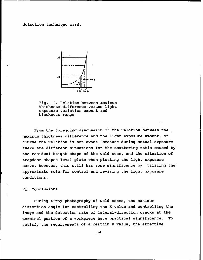
detection technique card.
is35
Fig. 12. Relation between maximumthickness difference versus lightexposure variation amount andblackness range
From the foregoing discussion of the relation between the
maximum thickness difference and the light exposure amount, of
course the relation is not exact, because during actual exposure
there are different situations for the scattering ratio caused by
the residual height shape of the weld seam, and the situation of
trapdoor shaped level plate when plotting the light exposure
curve, however, this still has some significance by "tilizing the
approximate rule for control and revising the light .xposure
conditions.
VI. Conclusions
During X-ray photography of weld seams, the maximum
distortion angle for controlling the K value and controlling the
image and the detection rate of lateral-direction cracks at the
terminal portion of a workpiece have practical significance. To
satisfy the requirements of a certain K value, the effective
34
exposure length for each light exposure of 100% examination of
annular weld seams should be properly calculated. Generally, a
weld seam has a residual height; when controlling the maximum K
value, there is a direct significance for tube voltage and light
exposure amount required to control and satisfy the blackness
range and the requirement of sensitivity of the image quality
meter. By combining and utilizing the basically consistent
condition of the light exposure curve and the film property
curve, the maximum K value can be controlled within the range
required by the level of image quality.
REFERENCES
1. Eastman Kodak Co., Radiography in Modern Industry, fourthedition, 1980.
2. Agfa-Gevaert, Industrial Radiography.
3. Deutsche Gesellschaft fur Zerstorungsfreie Prufung,Durchstrahlunasprufung fur Ingenieure (Kursus).
4. Japan Association of Nondestructive Inspection: PenetrionExperiment B of Radiation Rays, 1986; Penetrating ExperimentA of Radiation Rays, 1985.
5. Materialprufung, July 1984, Vol. 26, No. .
6. BS 2600/1-1973.
7. ISO R1106-1972.
35
IDENTIFICATION AND INVESTIGATION OF INCOMPLETE FUSION OF WELDS ON
RADIOGRAPHS
Xin Zhongren and Ma Mingqiu, Sichuan Provincial Department of
Labor and Personnel
Xin Zhongzhi, Chengdu Municipal Labor Bureau
Yang Jinjian, Neijiang Municipal Labor Bureau
Definitions and classification of incomplete fusions of
welds are described. The appearance, orientation and features of
incomplete fusions on radiographs are discussed and their
identification methods are presented. Additionally, the main
reasons for incomplete fusion are studied, based on welding
methods and weld structures.
Welding is the main technique in fabricating boilers and
pressure vessels; welding quality represents the fabrication
quality of boilers and pressure vessels.
As is well known, the process of welding metals proceeds
under conditions of thermodynamic inequilibrium. Because of the
metallurgical factors of the metal materials and the specific
technical factors of product manufacture, as well as the
comprehensive function of structural factors due to the weldment
design, especially when welding complex geometrically shaped
joints and highly concentrated stressed areas, welding is a
36
heat treatment techniques.
In the welding process, incomplete fusion is a common
technical defect with relatively serious hazards. To raise the
quality of welding techniques and the useful service life of
weldments, identification and overcoming of incomplete fusion
becomes a problem calling for an urgent solution in welding
techniques. However, it is not easy to determine correctly the
images of incomplete fusion on radiographic negatives because it
is very easy to be confused between the one-sided welding of root
incomplete fusion and one-sided welding of root incomplete
penetration. Thus, incomplete fusion is mistakenly understood as
incomplete penetration, with the result that even the defect of
incomplete fusion cannot be distinguished, leading to a
misevaluation between incomplete fusion of edge slope and slag
inclusions, and a confusion of incomplete fusion (interlayer
incomplete fusion) between welding passes and slag inclusions.
On the radiographic negatives of weld seams, the image of
incomplete fusion has features of a certain size, orientation,
and appearance; only by mastering these features and by
understanding the reasons underlying welding techniques and
structures for causing incomplete fusion can one easily
distinguish between incomplete fusion and other welding defects
from radiographic negatives.
Definition and Classification of Incomplete Fusion
As indicated from the standard GB 3375-82, "Welding--
Technical Terms," and ISO 6520, "Classification and Description
of Metal Weld Seam Defects (1982)," incomplete fusion is the
portion of incomplete fusion between the weld pass and the parent
material or between two adjacent weld passes (or the incomplete
fusion between parent material and parent material in spot
welding).
37
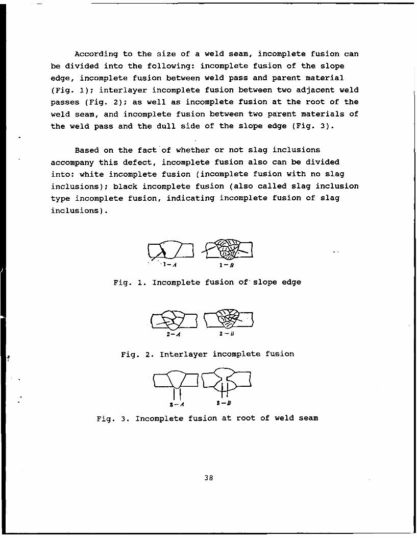
According to the size of a weld seam, incomplete fusion can
be divided into the following: incomplete fusion of the slope
edge, incomplete fusion between weld pass and parent material
(Fig. 1); interlayer incomplete fusion between two adjacent weld
passes (Fig. 2); as well as incomplete fusion at the root of the
weld seam, and incomplete fusion between two parent materials of
the weld pass and the dull side of the slope edge (Fig. 3).
Based on the fact of whether or not slag inclusions
accompany this defect, incomplete fusion also can be divided
into: white incomplete fusion (incomplete fusion with no slag
inclusions); black incomplete fusion (also called slag inclusion
type incomplete fusion, indicating incomplete fusion of slag
inclusions).
'-A I-B
Fig. 1. Incomplete fusion of slope edge
2-A 2 -U
Fig. 2. Interlayer incomplete fusion
- A,-B
Fig. 3. Incomplete fusion at root of weld seam
38
Incomplete Fusion of One-sided Weld Root and Incomplete
Penetration at Root
One-sided incomplete fusion at a weld root indicates the
sides have no fusion or incomplete fusion between the bottom weld
beam and the dull side of the parent material. At this time, the
metal at the weld seam has filled the gap of the dull side, and
the weld beams at the back are higher than the parent material.
As verified by experiments, whether white or black
incomplete fusion, visible images can be left on the radiographic
negatives; these images can be examined with radiography. This
is because incomplete fusion or incomplete melting occurred at
the dull side of the parent material slope edge; the dull side in
the case of incomplete fusion or incomplete melting leaves a
regular image on the photographic negatives.
Incomplete fusion at the root in one-sided welding leaves a
visible and characteristic image on the radiographic negatives;
at the dull side of the weld seam slope edge, there are regular
long, slender, black lines in the longitudinal direction of the
weld seam.
Because in this situation, the root of the weld seam is
higher than the parent material, therefore if one examines only
the appearance of the weld test plate, it can be concluded that
the formation at the back of the weld seam is acceptable; the
root of the weld seam is not only thoroughly penetrated, but also
is free of the incomplete fusion defect. From the radiographic
negatives, there is a relatively bright region at the gap of the
weld seam root; this also indicates that the back surface of the
weld seam has been thoroughly penetrated since the weld seam
metal is higher than the parent material. However, if one
closely observes the radiographic negatives, it can be discovered
39
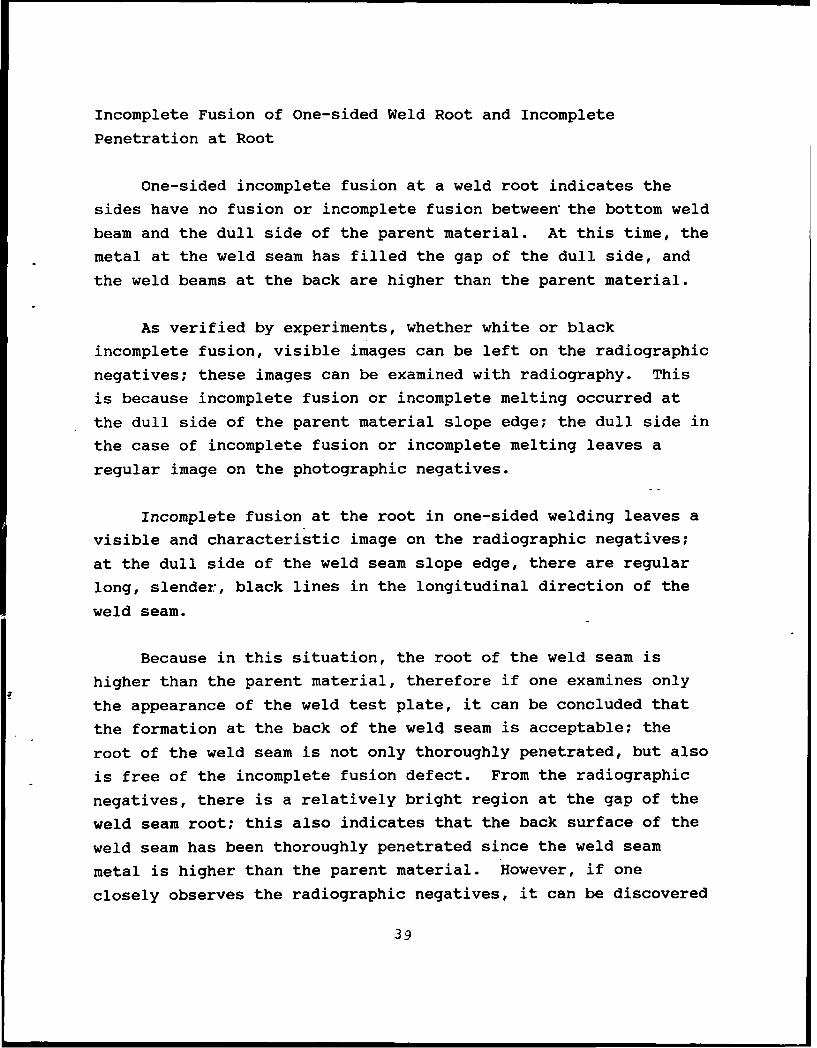
that regular long, slender, black straight lines appear in the
longitudinal direction of the weld seam at the dull side of the
weld seam slope edge (refer to Fig. 4).
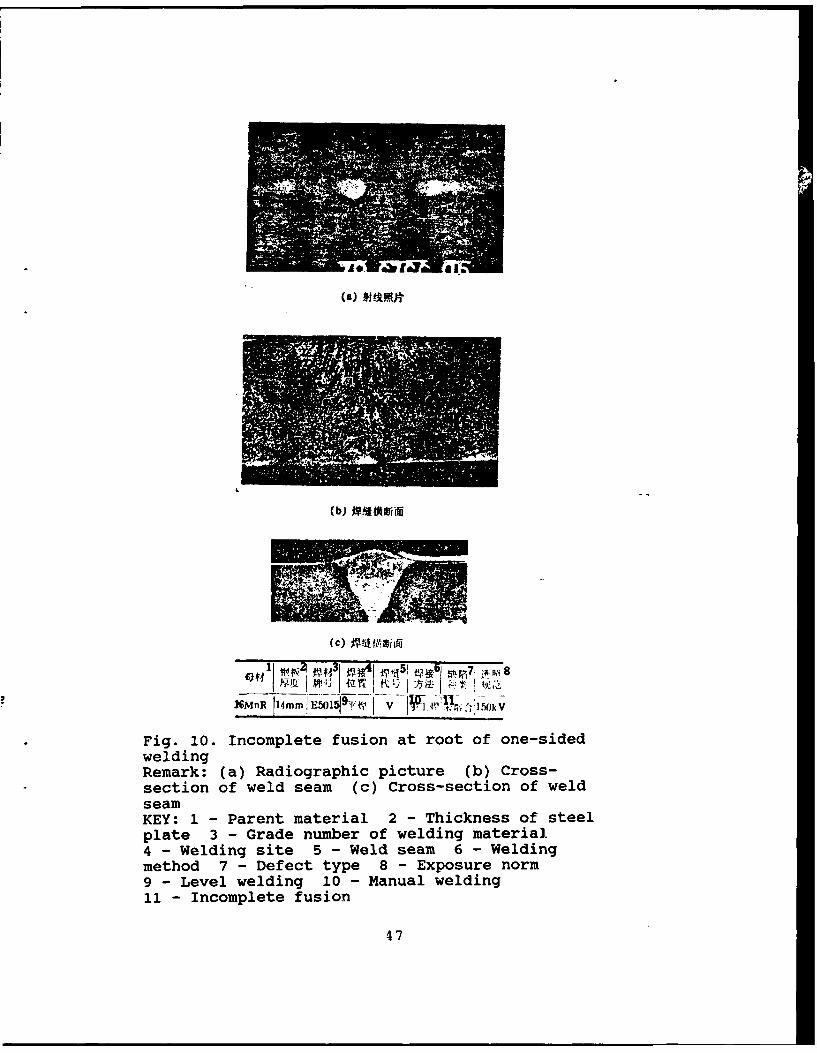
Fig. 4. Incomplete fusion at root inone-sided welding
After dissecting a weld seam test specimen and conducting a
metallographic inspection on the lateral cross-section of the
test specimen (refer to Fig. 10), it can be determined that the
incomplete fusion defect at the weld seam root occurs when
regular long slender black lines appear in the radiographic-
negatives.
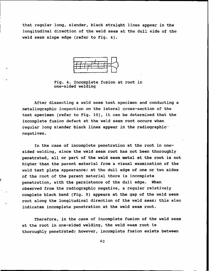
In the case of incomplete penetration at the root in one-
sided welding, since the weld seam root has not been thoroughly
penetrated, all or part of the weld seam metal at the root is not
higher than the parent material from a visual examination of the
weld test plate appearance; at the dull edge of one or two sides
of the root of the parent material there is incomplete
penetration, with the persistence of the dull edge. When
observed from the radiographic negative, a regular relatively
complete black band (Fig. 5) appears at the gap of the weld seam
root along the longitudinal direction of the weld seam; this also
indicates incomplete penetration at the weld seam root.
Therefore, in the case of incomplete fusion of the weld seam
at the root in one-sided welding, the weld seam root is
thoroughly penetrated; however, incomplete fusion exists between
40
weld seam metal and the parent material metal at the weld seam
root; in other words, no intracrystalline bonding occurs.
Fig. 5. Incomplete penetration of root inone-sided welding
Incomplete Fusion at Root in Double-sided Welding
Incomplete fusion at the root in double-sided welding occurs
at the dull side of the weld seam slope edge, with X or I slope
edge, see Fig. 3B. As verified in experiments, whether white or
black incomplete fusion there is a clear image in the
radiographic negative; this kind of image can be examined by the
radiographic method.
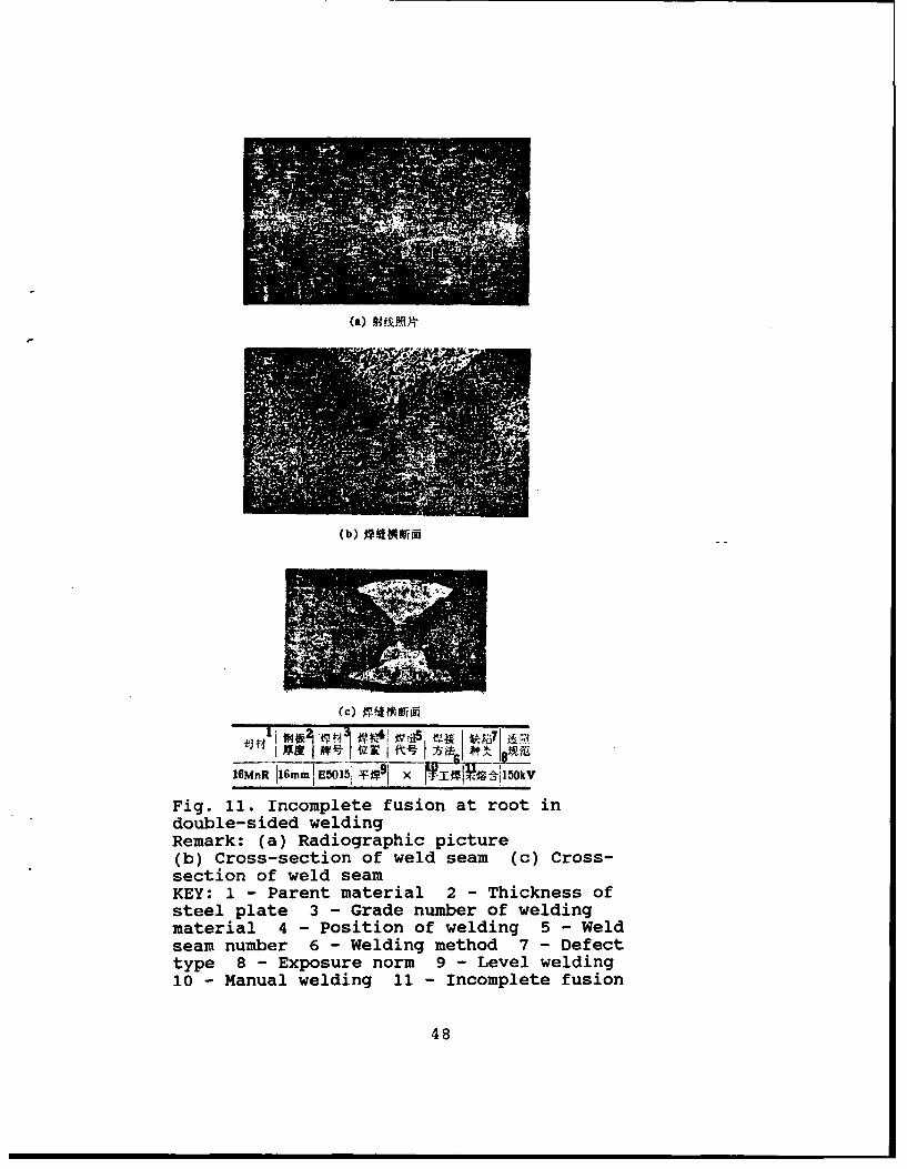
Incomplete fusion at the root in double-sided welding
produces well-defined images in the radiographic negative; at the
dull side of the weld seam slope edge, in the longitudinal
direction of the weld seam, the image is a regular long, slender,
black straight line (refer to Fig. 11).
Incomplete fusion and incomplete penetration at the root in
double-sided welding are two kinds of defects with different
properties. Incomplete penetration at the root in double-sided
welding is due to incomplete, or only partial overlapping of the
weld seam metal at the weld pass of the front and reverse side,
thus the parent material at the root of the weld seam is
incompletely penetrated, forming the defect. In this situation,
there are gaps between two weld passes at the front and reverse
sides; therefore, a regular, relatively coarse black straight
41
line appears in the radiographic negative for the case of
incomplete pepetration.
However, incomplete fusion of double-sided weld root portion
is due to overlapping of the metals at the front and reverse side
weld passes. However, due to insufficient energy in the welding
rod, although the gap of the weld seam slope edge is filled with
weld seam metal, yet the dull side of the parent material has not
been melted or is incompletely melted; thus, there is no
intracrystalline bonding because there is only mechanical contact
between the weld seam metal and the parent material at the dull
side. Since there is no gap at the weld seam root, no regular
long, slender, black lines are melted at the root portion in
double-sided welding (refer to Fig. 11).
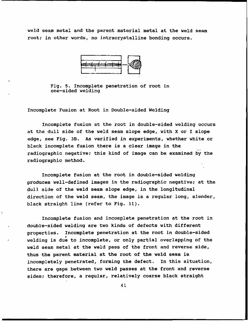
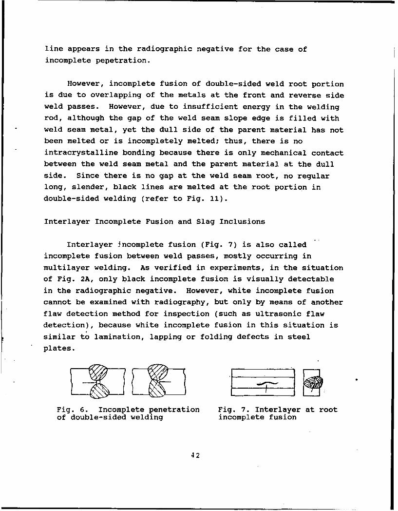
Interlayer Incomplete Fusion and Slag Inclusions
Interlayer incomplete fusion (Fig. 7) is also called
incomplete fusion between weld passes, mostly occurring in
multilayer welding. As verified in experiments, in the situation
of Fig. 2A, only black incomplete fusion is visually detectable
in the radiographic negative. However, white incomplete fusion
cannot be examined with radiography, but only by means of another
flaw detection method for inspection (such as ultrasonic flaw
detection), because white incomplete fusion in this situation is
similar to lamination, lapping or folding defects in steel
plates.
Fig. 6. Incomplete penetration Fig. 7. Interlayer at rootof double-sided welding incomplete fusion
42
In the situation of Fig. 2B, as verified with experiments,
whether white or black incomplete fusion, it can be inspected
with radiography because gaps are present between weld passes,
even in the case of white incomplete fusion, yielding visible
images on the radiographic negative.
For black interlayer incomplete fusion, this is also a
planar type defect; so the image on the radiographic negative has
features of these two kinds of defect owing to the existence of
slag inclusions and incomplete fusion; thus, there are block or
stripe-shaped irregular black shadows on the radiographic
negative similar to slag inclusions. However, the shade of the
black image is relatively light, with uneven black and white
distribution inside. The edge is relatively blurred, not well-
defined and lacking a regular shape. However, the slag inclusion
defect at a weld seam is a three-dimensional type defect,
although there is no fixed shape displaying a black shadow on the
radiographic negative; however, in the general situation the
color of the image on the radiographic negative is relatively
dark, basically with consistent blackness and relatively well-
pronounced outlines.
Slag inclusions situated between welding passes can be
A treated as incomplete fusion of slag inclusions. However, slag
inclusions in each welding pass cannot be treated as incomplete
fusion.
Radiographic flaw detection personnel can fabricate an
interlayer incomplete fusion test plate of butt weld seam
according to the specific welding technique prior to radiographic
exposure. In addition, comparative observations and analysis
between the typical weld seam interlayer incomplete fusion
radiographic negative and the slag inclusion negative should be
43
carried out for familiarization with the features of these two
defect images and the difference in appearance and shape in order
to determine correctly and distinguish these two types of weld
defects through radiographic inspection.
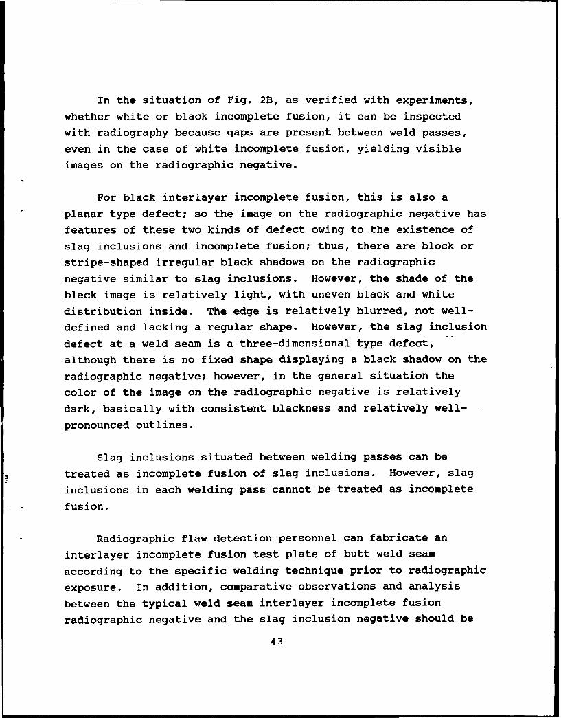
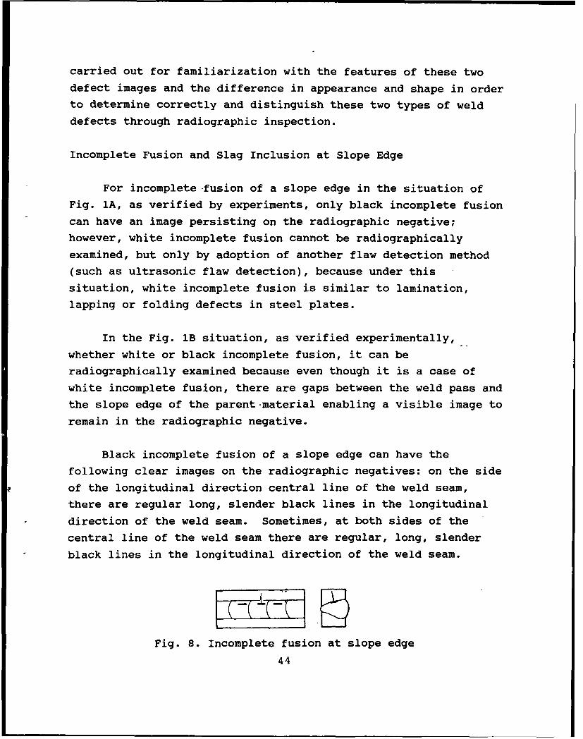
Incomplete Fusion and Slag Inclusion at Slope Edge
For incomplete -fusion of a slope edge in the situation of
Fig. 1A, as verified by experiments, only black incomplete fusion
can have an image persisting on the radiographic negative;
however, white incomplete fusion cannot be radiographically
examined, but only by adoption of another flaw detection method
(such as ultrasonic flaw detection), because under this
situation, white incomplete fusion is similar to lamination,
lapping or folding defects in steel plates.
In the Fig. lB situation, as verified experimentally,
whether white or black incomplete fusion, it can be
radiographically examined because even though it is a case of
white incomplete fusion, there are gaps between the weld pass and
the slope edge of the parent-material enabling a visible image to
remain in the radiographic negative.
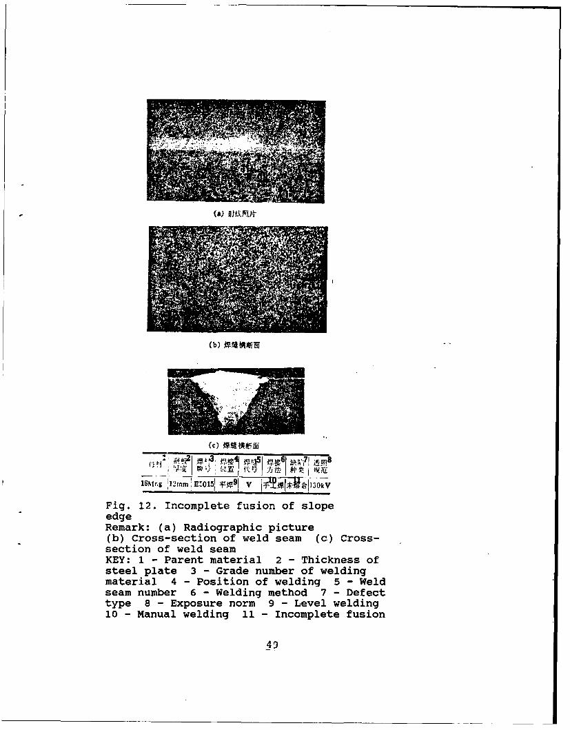
Black incomplete fusion of a slope edge can have the
following clear images on the radiographic negatives: on the side
of the longitudinal direction central line of the weld seam,
there are regular long, slender black lines in the longitudinal
direction of the weld seam. Sometimes, at both sides of the
central line of the weld seam there are regular, long, slender
black lines in the longitudinal direction of the weld seam.
Fig. 8. Incomplete fusion at slope edge
44
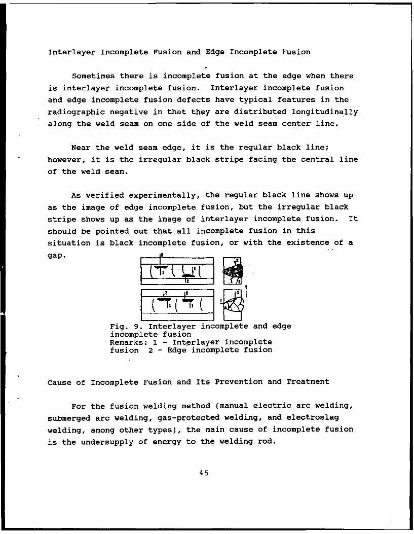
Interlayer Incomplete Fusion and Edge Incomplete Fusion
Sometimes there is incomplete fusion at the edge when there
is interlayer incomplete fusion. Interlayer incomplete fusion
and edge incomplete fusion defects have typical features in the
radiographic negative in that they are distributed longitudinally
along the weld seam on one side of the weld seam center line.
Near the weld seam edge, it is the regular black line;
however, it is the irregular black stripe facing the central line
of the weld seam.
As verified experimentally, the regular black line shows up
as the image of edge incomplete fusion, but the irregular black
stripe shows up as the image of interlayer incomplete fusion. It
should be pointed out that all incomplete fusion in this
situation is black incomplete fusion, or with the existence of a
gap.
12 1212 1
Fig. 9. Interlayer incomplete and edgeincomplete fusionRemarks: 1 - Interlayer incompletefusion 2 - Edge incomplete fusion
Cause of Incomplete Fusion and Its Prevention and Treatment
For the fusion welding method (manual electric arc welding,
submerged arc welding, gas-protected welding, and electroslag
welding, among other types), the main cause of incomplete fusion
is the undersupply of energy to the welding rod.
45
For example, in the case of manual electric arc welding, in
carrying out the first welding pass for a single V-slope edge
butt weld seam one-sided welding, due to inappropriate welding
rod motion, the electric arc deviates to one side of the slope
edge of the parent material, then the slope edge at another side
of the parent material is covered with filler metal prior to
fusion, thus causing incomplete fusion at the root. In this
situation when the welding rod energy is too small and incomplete
fusion is caused at both sides of the root of the slope edge of
the parent material.
When multilayer welding is conducted with submerged-arc
automatic welding, when the automatic welding speed of the
submerged arc is suddenly increased, the welding rod energy will
suddenly drop. Then interlayer incomplete fusion is the result,
between the front layer of the weld seam and the rear layer of
the weld seam.
According to GB 3323-87 Standardi Classification Method for
Steel Weld Seam Radiographic Pictures and Negatives, any kind of
incomplete fusion is an unacceptable welding defect; once
incomplete fusion occurs in a weld seam, on the one hand the
cause of the incomplete welding defect should be analyzed in
order to avoid another occurrence of the defect. On the other
hand, the incomplete fusion should be cleared with supplementary
welding.
Typical Pictures of Incomplete Fusion Defects
46
(a) # Af
2HMnR 114..!E501 TtV V~W ~.~5k
Fig. 10. Incomplete fusion at root of one-sidedweldingRemark: (a) Radiographic picture (b) Cross-section of weld seam (c) Cross-section of weldseamKEY: 1 - Parent material 2 - Thickness of steelplate 3 - Grade number of welding material4 - Welding site 5 - Weld seam 6 - Weldingmethod 7 - Defect type 8 - Exposure norm9 - Level welding 10 - Manual welding11 - Incomplete fusion
47
(a) 3I4
(b) O~t$rf
16MnR 116mm IE50151 T I k
Fig. 11. Incomplete fusion at root indouble-sided weldingRemark: (a) Radiographic picture(b) Cross-section of weld seam (c) Cross-section of weld seamKEY: 1 - Parent material 2 - Thickness ofsteel plate 3 - Grade number of weldingmaterial 4 - Position of welding 5 - Weldseam number 6 - Welding method 7 - Defecttype 8 - Exposure norm 9 - Level welding10 - Manual welding 11 - Incomplete fusion
48
(b)
it R~ -t I ti
l6Mr.g !'2m' EZ015', 3*9 V iVIg~i~k
Fig. 12. Incomplete fusion of slopeedgeRemark: (a) Radiographic picture(b) Cross-section of weld seam (c) Cross-section of weld seamKEY: 1 - Parent material 2 - Thickness ofsteel plate 3 - Grade number of weldingmaterial 4 - Position of welding 5 - Weldseam number 6 - Welding method 7 - Defecttype 8 - Exposure norm 9 - Level welding10 - Manual welding 11 - Incomplete fusion
49
(a) VAN#
(b) ffiti
(C)
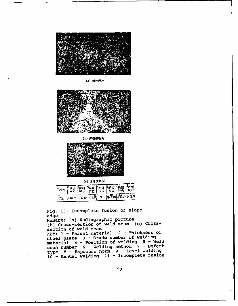
ME JfYq 1 )5 1 # k )20g 11mm E1315 -1 V_ VV
Fig. 13. Incomplete fusion of slope
edgeRemark: (a) Radiographic picture(b) Cross-section of weld seam (c) Cross-section of weld seamKEY: 1 - Parent material 2 - Thickness of
steel plate 3 - Grade number of welding
material 4 - Position of welding 5 - Weld
seam number 6 - welding method 7 - Defect
type 8 - Exposure norm 9 - Level welding
10 - Manual welding 11 - Incomplete fusion
50
(a) l~t
(Cb) X ft 1A if
(C) ~i~
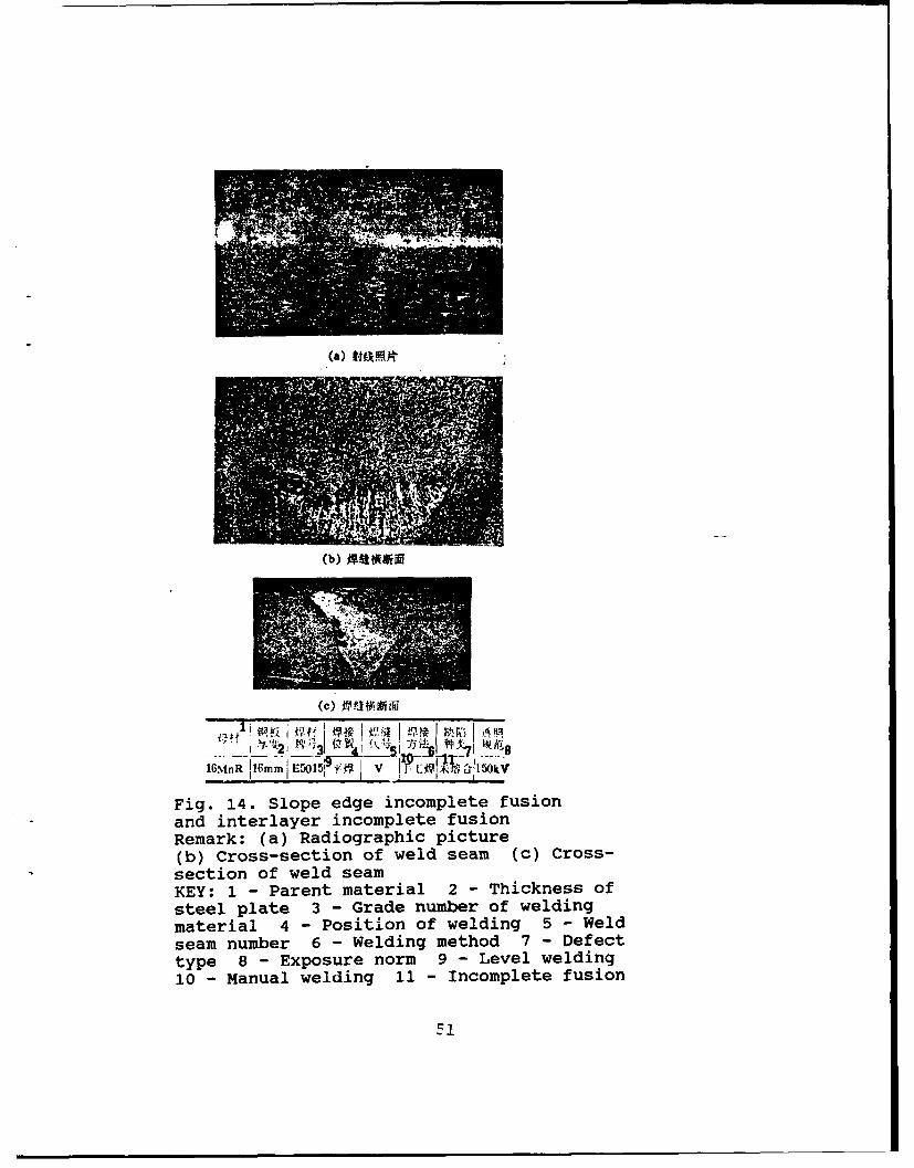
1 2 i3 8P)1 h16,%nR 16mm1 E5015: RXF 1 ~ '*~?~i5OkV
Fig. 14. Slope edge incomplete fusionand interlayer incomplete fusionRemark: (a) Radiographic picture(b) Cross-section of weld seam (c) Cross-section of weld seamKEY: 1 - Parent material 2 - Thickness of
steel plate 3 - Grade number of weldingmaterial 4 - Position of welding 5 - Weldseam number 6 - Welding method 7 - Defecttype 8 - Exposure norm 9 - Level welding10 - Manual welding 11 - Incomplete fusion
F1
NEW METHOD OF NONDESTRUCTIVE TESTING OF INTERNAL STRESSES--
MAGNETIC ACOUSTIC EMISSION*
Xu Yuehuang, Du Fengmu, and Shen Gongtian, Wuhan University
Magnetic acoustic emission (MAE) refers to the generation of
stress versus strain waves when a ferromagnetic material is
magnetized by a varying magnetic field. MAE can be used as a new
field for nondestructive testing of internal stresses. The
characteristics of MAE in several kinds of finished steel
products are introduced. The effects of stress, chemical
composition, heat treatment and temperature on MAE are discussed.
The depth that can be measured by MAE is about 3-4mm at the
frequency of 50Hz. Application of the ratio of MAE values under
different magnetic fields to determine internal stresses is
feasible.
Foreword
The existence of internal stresses greatly reduces the
bearing capacity of a structural member, thus introducing a lack
of safety vector. Therefore, in production practice the internal
stresses existing in a material often need to be understood. For
a long time already, numerous researchers exerted their best
efforts in searching for methods of detecting internal stress
with precision, reliability, simplicity and feasibility.
*This is a research project funded by the Science Foundation,Chinese Academy of Sciences.
52
The X-ray method is reliable, since it does not damage the
workpiece to be examined; the area to be examined can be selected
and the method can be used to detect internal stresses in a
smaller region. Shortcomings of the method are that it reveals
defects in depths only tens of micrometers deep for flaw
detection, complex equipment is needed, and there is
inconvenience in on-site testing.
By determining precisely the propagation rate of ultrasoric
waves in a material, the ultrasonic wave method can determine the
magnitude of internal stresses with a short test period and
instrumental portability. The method can easily serve in the
inspection of surface and internal regions for internal stresses
of an object; however, there are a fair number of factors
affecting the results of measurements.
In addition, there are also the strain gage method,
photoelastic method, Mossbauer effect and neutron diffraction,
among others. There are pros and cons concerning these methods.
Magnetic acoustic emission (MAE) is another new method.
Since it is affected by an alternately changing magnetic
field, ferromagnetic material can emit stress, strain waves
because of reciprocating oscillation of magnetic domain walls and
the rotation of the magnetization vector; this is due to sonic
emission. Some consider that sonic emission is related to the
magnetostrictive effect; therefore, it is also called
magnetomechanical acoustic emission (MAE). Measurement of
internal stress with the MAE technique is based on the
interdependent relation between the magnetic acoustic emission
with the stress. Kusanagi et al [1] was the first to discover
the close relationship between magnetic acoustic emission and
stress in materials; under the condition of relatively high
stress, notwithstanding the tensile or compressive stress in the
material, the intensity of magnetic acoustic emission is always
53
appreciably lower than in the nonstress case. Ono and Shibata
[2, 3] conducted a more detailed study on magnetic acoustic
emission of ferronickel alloys and several types of steel; they
discovered that the chemical composition, microscopic texture,
stress and precooling treatment (among other factors) of the
material considerably affect the magnetic acoustic emission
behavior; they considered that the magnetic acoustic emission
technique can possibly become a new nondestructive test method
for residual stresses in structural members and other properties
[4, 5].
After Ono and Shibata [3) analyzed numerous experimental
results, they concluded that the main source of magnetic acoustic
emission originates in the displacement variation caused by
motion of 900 magnetic domain walls, and secondarily it
originates from the rotation of the magnetization vector; the
motion of 1800 domain walls does not produce magnetic acoustic
emission. The peak voltage for the MAE pulse signal is
In the equation: C1 -- constant;
AV -- variation of magnetic domain volume;
A6 -- nonelastic strain tensor in AV;
T -- rise time of signal.
Based on experimental facts, the authors made supplements to the
above-mentioned model, since they considered that magnetic domain
walls as such have a strain field; the process of domain wall
motion will release a strain wave. Therefore, whether 900 or
1800 domain wall, an elastic wave will be released upon the
motion of an alternately varying magnetic field.
Abroad, at present the MAE technique has been used in the
nondestructive testing of internal stresses in artillery shells,
rifle barrels, and self-propelled guns, in stress testing after
welding and heat treatment and in monitoring stress variations in
applications of structural members. In California, some
54
researchers applied this method to detect internal stresses
caused by thermal expansion and contraction due to cooling of
steel rail [5]. Practical applications of MAE still remain to be
broadly developed. The authors measured magnetic acoustic
emission in several materials and discussed how MAE is affected
by stress and other factors. They considered that magnetic
acoustic emission can certainly become a nondestructive test
method for internal stresses.
Experimental Conditions
The test specimens used were rod-shaped or strip-shaped;
other than the specific heat treatment norm applied to the
specimen, all others were in the annealing stage. Refer to
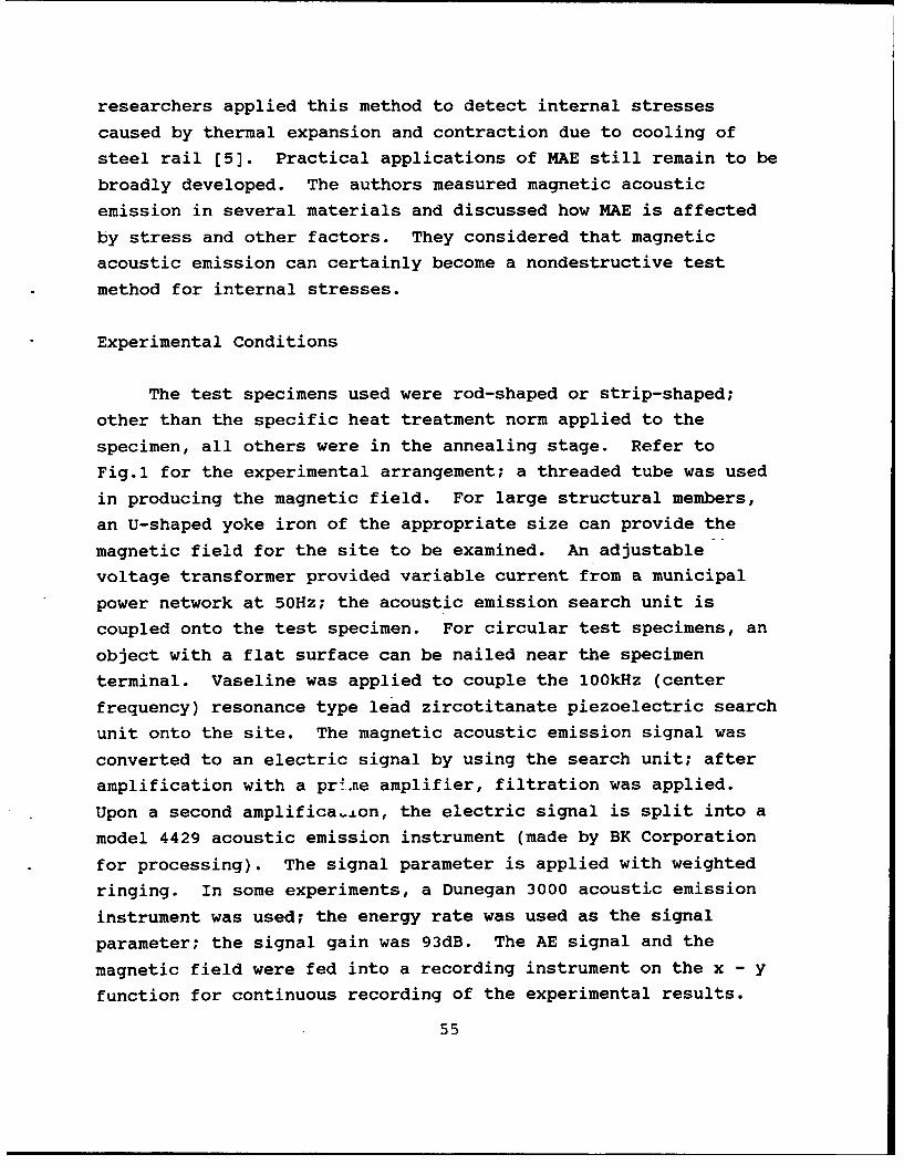
Fig.1 for the experimental arrangement; a threaded tube was used
in producing the magnetic field. For large structural members,
an U-shaped yoke iron of the appropriate size can provide the
magnetic field for the site to be examined. An adjustable
voltage transformer provided variable current from a municipal
power network at 50Hz; the acoustic emission search unit is
coupled onto the test specimen. For circular test specimens, an
object with a flat surface can be nailed near the specimen
terminal. Vaseline was applied to couple the 100kHz (center
frequency) resonance type lead zircotitanate piezoelectric search
unit onto the site. The magnetic acoustic emission signal was
converted to an electric signal by using the search unit; after
amplification with a prim.ie amplifier, filtration was applied.
Upon a second amplifica.±on, the electric signal is split into a
model 4429 acoustic emission instrument (made by BK Corporation
for processing). The signal parameter is applied with weighted
ringing. In some experiments, a Dunegan 3000 acoustic emission
instrument was used; the energy rate was used as the signal
parameter; the signal gain was 93dB. The AE signal and the
magnetic field were fed into a recording instrument on the x - y
function for continuous recording of the experimental results.
55
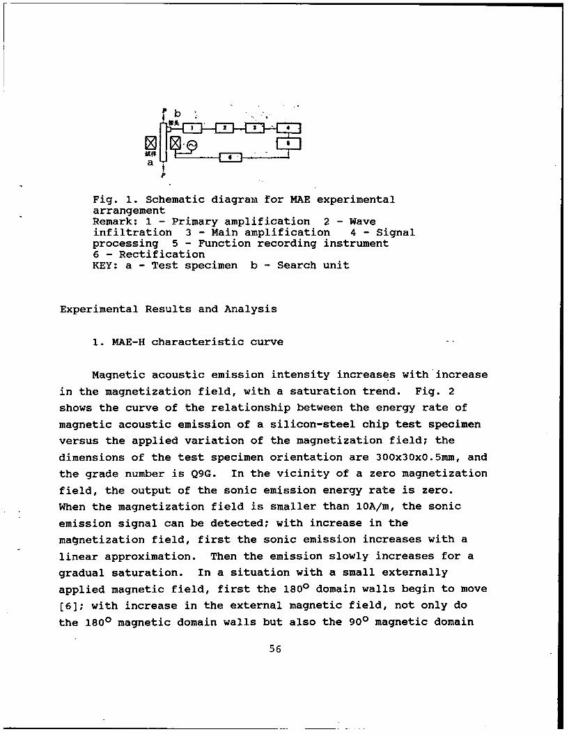
P b
!4
P
Fig. 1. Schematic diagram for MAE experimentalarrangementRemark: 1 - Primary amplification 2 - Waveinfiltration 3 - Main amplification 4 - Signalprocessing 5 - Function recording instrument6 - RectificationKEY: a - Test specimen b - Search unit
Experimental Results and Analysis
1. MAE-H characteristic curve
Magnetic acoustic emission intensity increases with increase
in the magnetization field, with a saturation trend. Fig. 2
shows the curve of the relationship between the energy rate of
magnetic acoustic emission of a silicon-steel chip test specimen
versus the applied variation of the magnetization field; the
dimensions of the test specimen orientation are 300x30x0.Smm, and
the grade number is Q9G. In the vicinity of a zero magnetization
field, the output of the sonic emission energy rate is zero.
When the magnetization field is smaller than 10A/m, the sonic
emission signal can be detected; with increase in the
magnetization field, first the sonic emission increases with a
linear approximation. Then the emission slowly increases for a
gradual saturation. In a situation with a small externally
applied magnetic field, first the 1800 domain walls begin to move
[6]; with increase in the external magnetic field, not only do
the 1800 magnetic domain walls but also the 900 magnetic domain
56
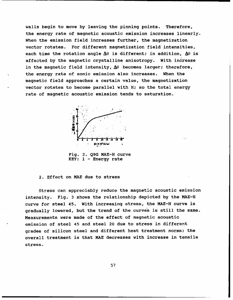
walls begin to move by leaving the pinning points. Therefore,
the energy rate of magnetic acoustic emission increases linearly.
When the emission field increases further, the magnetization
vector rotates. For different magnetization field intensities,
each time the rotation angle A@ is different; in addition, AO is
affected by the magnetic crystalline anisotropy. With increase
in the magnetic field intensity, AO becomes larger; therefore,
the energy rate of sonic emission also increases. When the
magnetic field approaches a certain value, the magnetization
vector rotates to become parallel with H; so the total energy
rate of magnetic acoustic emission tends to saturation.
j" (XI'A/M)
Fig. 2. Q9G MAE-H curveKEY: 1 - Energy rate
2. Effect on MAE due to stress
Stress can appreciably reduce the magnetic acoustic emission
intensity. Fig. 3 shows the relationship depicted by the MAE-H
curve for steel 45. With increasing stress, the MAE-H curve is
gradually lowered, but the trend of the curves is still the same.
Measurements were made of the effect of magnetic acoustic
emission of steel 45 and steel 20 due to stress in different
grades of silicon steel and different heat treatment norms; the
overall treatment is that MAE decreases with increase in tensile
stress.
57
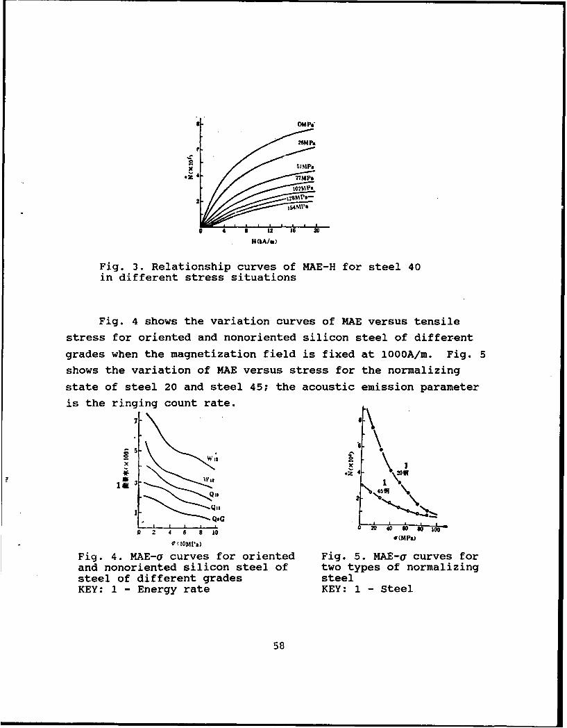
NMPa
Fig. 3. Relationship curves of MAE-H for steel 40in different stress situations
Fig. 4 shows the variation curves of MAE versus tensile
stress for oriented and nonoriented silicon steel of different
grades when the magnetization field is fixed at 1000A/m. Fig. 5
shows the variation of MAE versus stress for the normalizing
state of steel 20 and steel 45; the acoustic emission parameter
is the ringing count rate.7
4. (MMP)2 41L 6 8L 2 L
H&APa)
0" ( OMl'a)Fig. 4. MAE-l curves for oriented Fig. 5. MAE-g curves forand nonoriented silicon steel of two types of normalizingsteel of different grades steelKEY: 1 - Energy rate KEY: 1 - Steel
58
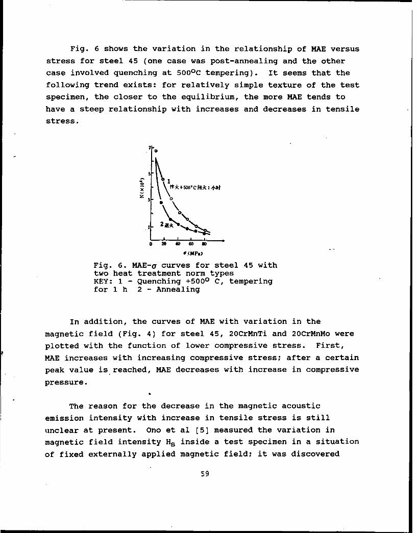
Fig. 6 shows the variation in the relationship of MAE versus
stress for steel 45 (one case was post-annealing and the other
case involved quenching at 5000 C tempering). It seems that the
following trend exists: for relatively simple texture of the test
specimen, the closer to the equilibrium, the more MAE tends to
have a steep relationship with increases and decreases in tensile
stress.
7 0
SI
2\ 0 \0
0 2040 0 S
Fig. 6. MAE-a curves for steel 45 withtwo heat treatment norm typesKEY: 1 - Quenching +5000 C, temperingfor 1 h 2 - Annealing
In addition, the curves of MAE with variation in the
magnetic field (Fig. 4) for steel 45, 20CrMnTi and 20CrMnMo were
plotted with the function of lower compressive stress. First,
MAE increases with increasing compressive stress; after a certain
peak value is reached, MAE decreases with increase in compressive
pressure.
The reason for the decrease in the magnetic acoustic
emission intensity with increase in tensile stress is still
unclear at present. Ono et al [5] measured the variation in
magnetic field intensity Hs inside a test specimen in a situation
of fixed externally applied magnetic field; it was discovered
59
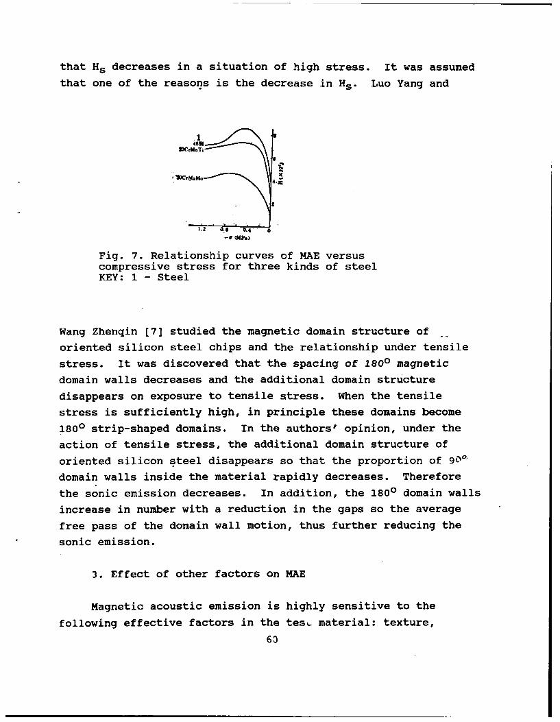
that Hs decreases in a situation of high stress. It was assumed
that one of the reasons is the decrease in Hs . Luo Yang and
WrU&Tir\
.22
1.2 0:0
Fig. 7. Relationship curves of MAE versuscompressive stress for three kinds of steelKEY: 1 - Steel
Wang Zhenqin [7] studied the magnetic domain structure of
oriented silicon steel chips and the relationship under tensile
stress. It was discovered that the spacing of 1800 magnetic
domain walls decreases and the additional domain structure
disappears on exposure to tensile stress. When the tensile
stress is sufficiently high, in principle these domains become
1800 strip-shaped domains. In the authors' opinion, under the
action of tensile stress, the additional domain structure of
oriented silicon steel disappears so that the proportion of 90 '
domain walls inside the material rapidly decreases. Therefore
the sonic emission decreases. In addition, the 1800 domain walls
increase in number with a reduction in the gaps so the average
free pass of the domain wall motion, thus further reducing the
sonic emission.
3. Effect of other factors on MAE
Magnetic acoustic emission is highly sensitive to the
following effective factors in the tesL. material: texture,
63
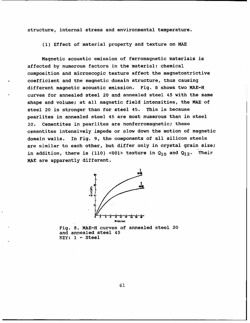
structure, internal stress and environmental temperature.
(1) Effect of material property and texture on MAE
Magnetic acoustic emission of ferromagnetic materials is
affected by numerous factors in the material: chemical
composition and microscopic texture affect the magnetostrictive
coefficient and the magnetic domain structure, thus causing
different magnetic acoustic emission. Fig. 8 shows two MAE-H
curves for annealed steel 20 and annealed steel 45 with the same
shape and volume; at all magnetic field intensities, the MAE of
steel 20 is stronger than for steel 45. This is because
pearlites in annealed steel 45 are most numerous than in steel
20. Cementites in pearlites are nonferromagnetic; these
cementites intensively impede or slow down the motion of magnetic
domain walls. In Fig. 9, the components of all silicon steels
are similar to each other, but differ only in crystal grain size;
in addition, there is (110) <001> texture in Q1 0 and Q1 2 - Their
MAE are apparently different.
1
Ix
44
2
10 12 4 W a
HiA/m)
Fig. 8. MAE-H curves of annealed steel 20and annealed steel 45KEY: 1 - Steel
61
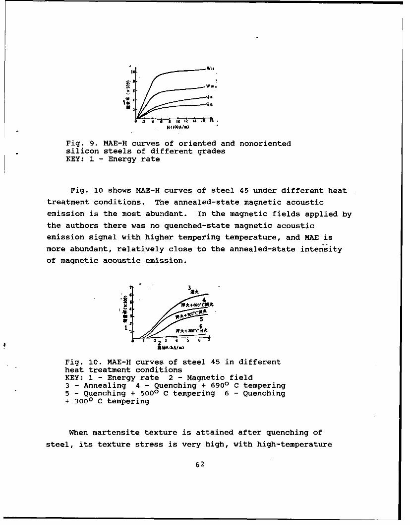
4 W14
l' Q3
.2 4 6 8 10 12 14 16 13H(IOQA/m)
Fig. 9. MAE-H curves of oriented and nonorientedsilicon steels of different gradesKEY: 1 - Energy rate
Fig. 10 shows MAE-H curves of steel 45 under different heat
treatment conditions. The annealed-state magnetic acoustic
emission is the most abundant. In the magnetic fields applied by
the authors there was no quenched-state magnetic acoustic
emission signal with higher tempering temperature, and MAE is
more abundant, relatively close to the annealed-state intensity
of magnetic acoustic emission.
3 A*
"' . 43
2. 5a2
.1 2 3 4 5 6*
aEAH (kA/n)
Fig. 10. MAE-H curves of steel 45 in differentheat treatment conditionsKEY: 1 - Energy rate 2 - Magnetic field3 - Annealing 4 - Quenching + 6900 C tempering5 - Quenching + 5000 C tempering 6 - Quenching+ 3000 C tempering
When martensite texture is attained after quenching of
steel, its texture stress is very high, with high-temperature
62
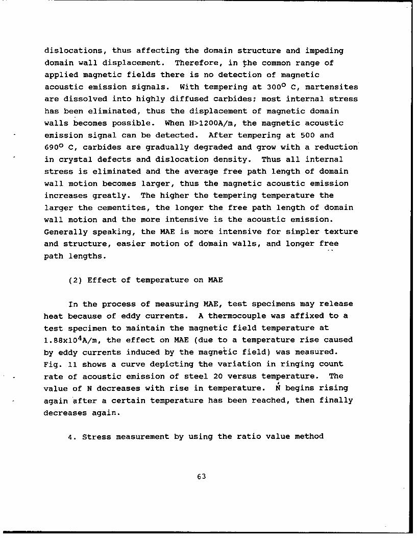
dislocations, thus affecting the domain structure and impeding
domain wall displacement. Therefore, in the common range of
applied magnetic fields there is no detection of magnetic
acoustic emission signals. With tempering at 3000 C, martensites
are dissolved into highly diffused carbides; most internal stress
has been eliminated, thus the displacement of magnetic domain
walls becomes possible. When H>1200A/m, the magnetic acoustic
emission signal can be detected. After tempering at 500 and
6900 C, carbides are gradually degraded and grow with a reduction
in crystal defects and dislocation density. Thus all internal
stress is eliminated and the average free path length of domain
wall motion becomes larger, thus the magnetic acoustic emission
increases greatly. The higher the tempering temperature the
larger the cementites, the longer the free path length of domain
wall motion and the more intensive is the acoustic emission.
Generally speaking, the MAE is more intensive for simpler texture
and structure, easier motion of domain walls, and longer free
path lengths.
(2) Effect of temperature on MAE
In the process of measuring MAE, test specimens may release
heat because of eddy currents. A thermocouple was affixed to a
test specimen to maintain the magnetic field temperature at
1.88x10 4A/m, the effect on MAE (due to a temperature rise caused
by eddy currents induced by the magnetic field) was measured.
Fig. 11 shows a curve depicting the variation in ringing count
rate of acoustic emission of steel 20 versus temperature. The
value of N decreases with rise in temperature. N begins rising
again after a certain temperature has been reached, then finally
decreases again.
4. Stress measurement by using the ratio value method
63
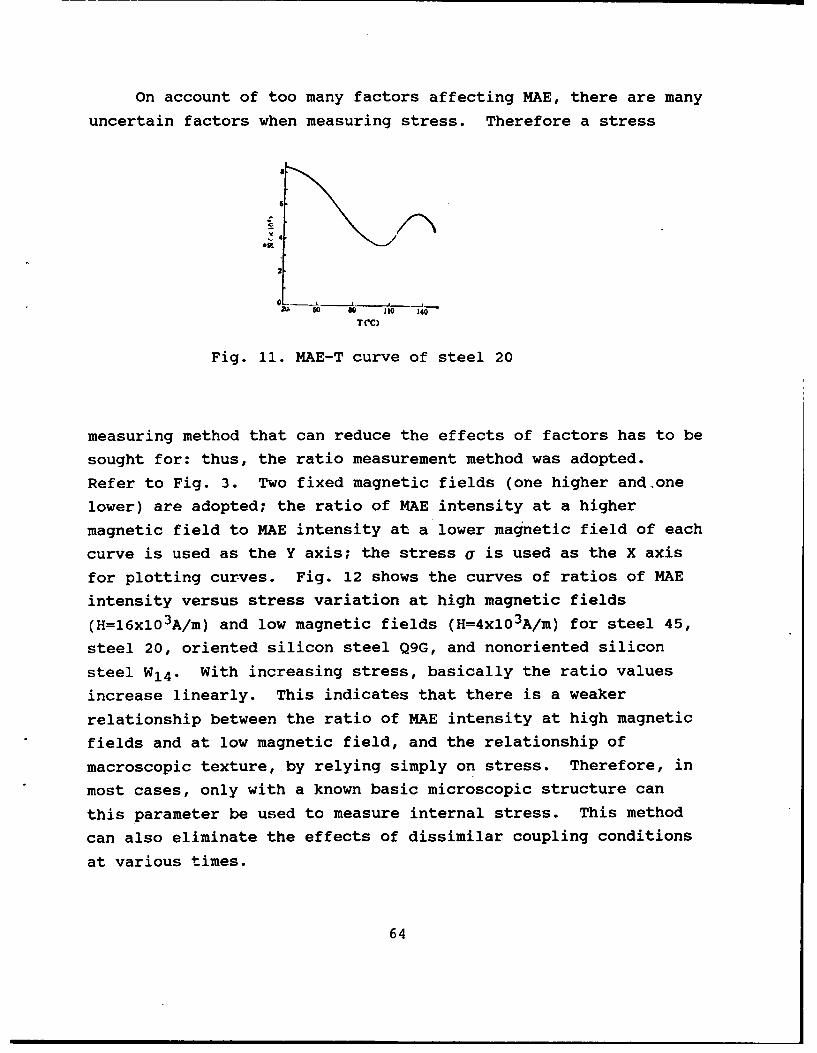
On account of too many factors affecting MAE, there are many
uncertain factors when measuring stress. Therefore a stress
a
6
l0- 10 140
T(IC)
Fig. 11. MAE-T curve of steel 20
measuring method that can reduce the effects of factors has to be
sought for: thus, the ratio measurement method was adopted.
Refer to Fig. 3. Two fixed magnetic fields (one higher and one
lower) are adopted; the ratio of MAE intensity at a higher
magnetic field to MAE intensity at a lower magnetic field of each
curve is used as the Y axis; the stress a is used as the X axis
for plotting curves. Fig. 12 shows the curves of ratios of MAE
intensity versus stress variation at high magnetic fields
(H=16xl03A/m) and low magnetic fields (H=4xl03A/m) for steel 45,
steel 20, oriented silicon steel Q9G, and nonoriented silicon
steel W14. With increasing stress, basically the ratio values
increase linearly. This indicates that there is a weaker
relationship between the ratio of MAE intensity at high magnetic
fields and at low magnetic field, and the relationship of
macroscopic texture, by relying simply on stress. Therefore, in
most cases, only with a known basic microscopic structure can
this parameter be used to measure internal stress. This method
can also eliminate the effects of dissimilar coupling conditions
at various times.
64
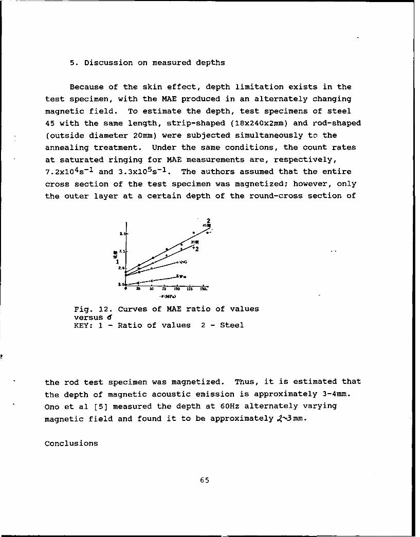
5. Discussion on measured depths
Because of the skin effect, depth limitation exists in the
test specimen, with the MAE produced in an alternately changing
magnetic field. To estimate the depth, test specimens of steel
45 with the same length, strip-shaped (18x240x2mm) and rod-shaped
(outside diameter 20mm) were subjected simultaneously to the
annealing treatment. Under the same conditions, the count rates
at saturated ringing for MAE measurements are, respectively,
7.2x10⁴s-1 and 3.3x10 5s-1 . The authors assumed that the entire
cross section of the test specimen was magnetized; however, only
the outer layer at a certain depth of the round-cross section of
2
f 0 2.5 +C 7 2 1.
2LG2
16(MPa)
Fig. 12. Curves of MAE ratio of valuesversus 6KEY: 1 - Ratio of values 2 - Steel
the rod test specimen was magnetized. Thus, it is estimated that
the depth of magnetic acoustic emission is approximately 3-4mm.
Ono et al [5] measured the depth at 60Hz alternately varying
magnetic field and found it to be approximately .,3mm.
Conclusions
65
1. Magnetic acoustic emission decreases with increase in
stress.
2. The composition, texture, environmental temperature and
coupling conditions of a material are highly sensitive to
magnetic acoustic emission.
3. By measuring internal stress with the ratio value method,
the effects of the material properties and the coupling
conditions of texture can be considerably reduced; this is a
feasible method for measuring internal stress by MAE.
4. The material depth at which magnetic acoustic emission is
produced at a 50Hz alternately varying magnetic field is
approximately 3-4mm.
REFERENCES
1. Kusanagi, H., H. Kimura and H. Sasaki, J. Azpl. Phys. 5Q_/4,2985 (1979).
2. Ono, K. and M. Shibata, Mater. Eval. 38, 55 (1980).
3. Ono, K. and M. Shibata, Advances in Acoustic Emission, editedby H. L. Dunegan and W. F. Havtman, Dunhart, Knoxville,p. 154, 1981.
4. Ono, K. and M. Shibata, Proc. Conf. NDT, Railway Adm.,American Association of Railroads, February (1979),Washington, D. C.
5. Shibata, M. and K. Ono, NDT International, 5, 227 (1981).
6. Guo Yicheng, TiQixue [Ferromagnetism], Higher EducationPublishing House, p. 440, 1965.
7. Luo Yang and Wang Zhengqin, Jinshu Xuebao [Metals], 12/2, A125(1983).
66
ANALYSIS OF ABNORMAL DEFECTS ON X-RAY FILMS
Li Lanrui and Li Tongchao
The acetylene gas bottles made in the authors' plant are in
the class three pressure vessel category, requiring 100%
radiographic inspection. The production of the gas bottles is on
a large scale so the assessment of the radiographic negatives is
a labor-intensive mission, requiring nearly 5000 negatives to be
assessed per day. Recently, in the assessment of negatives the
authors discovered some abnormal defects, such as black-and-white
rings; on the negatives there are circular rings of white at the
center and black at the circumference; however, the blackness in
the circle is equivalent to the normal weld seam blackness.
There were disputes on the flaw detection data that could not be
determined qualitatively. Some inspectors thought that these
defects were gas bubbles, while other inspectors thought that
these defects were due to sand inclusions, since gas bubbles are
imaged with greater blackness value at the center than the
periphery; for sand inclLsions, the value of blackness in the
circle should be slightly greater than the blackness value for a
normal weld seam. Therefore, the two above-mentioned qualitative
determinations are not precise enough.
Finally, through an analysis this kind of defects should be
determined as the column (a part of filler wire) inclusions.
This explanation has been verified after dissecting workpieces.
The reason for the existence of the above-mentioned defects is
67
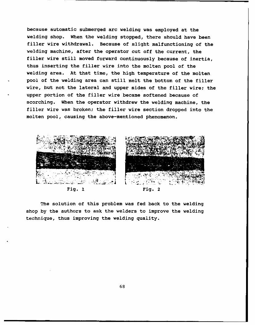
because automatic submerged arc welding was employed at the
welding shop. When the welding stopped, there should have been
filler wire withdrawal. Because of slight malfunctioning of the
welding machine, after the operator cut off the current, the
filler wire still moved forward continuously because of inertia,
thus inserting the filler wire into the molten pool of the
welding area. At that time, the high temperature of the molten
pool of the welding area can still melt the bottom of the filler
wire, but not the lateral and upper sides of the filler wire; the
upper portion of the filler wire became softened because of
scorching. When the operator withdrew the welding machine, the
filler wire was broken; the filler wire section dropped into the
molten pool, causing the above-mentioned phenomenon.
iJ-A ~A
- -''
L 4r~ ~Fig. 1 Fig. 2
The solution of this problem was fed back to the welding
shop by the authors to ask the welders to improve the welding
technique, thus improving the welding quality.
68
MEASUREMENT AND LOCATION OF WELDS FOR RADIOGRAPHIC INSPECTION
Sun Wenhai, Weifang Chemical Machinery Plant
The article mainly presents relatively precise locating and
methods of measuring weld seams and radiation source during an
exposure.
Based on different workpiece specifications under exposure,
the radiation source should be placed at the appropriate exposure
position. In actual operation when there are exposures at
different angles, the position of the radiation source and the
cemented-on film should be precisely measured and located. The
measurement procedure (Fig. 1) for weld seam exposure angles
serves mainly in exposing workpieces of large diameter, as well
as different height and angles. In the figure, solid lines
indicate the internal exposure method; dotted lines indicate
external exposure. During exposure, based on the diameter of the
workpiece to be exposed, the flexible joints between a straight
rod and a connecting rod are pulled in order to adhere the four-
joint plate (Fig. 1) tightly in the exposure position. The
central straight rod points toward the center of the radiation
source and is parallel to the central indicating rod on the
radiation beam window. Fig. 2 is mainly used on the occasion
when the internal and external central positions at the test film
of the workpiece seam under exposure cannot be easily measured
(not including T- or cross-shaped weld seams). For example, in
the case of the external method of weld seam exposure, the inside
diameter of the workpiece under exposure can have a film cemented
on it ahead of time, based on the site requiring exposure, and
69
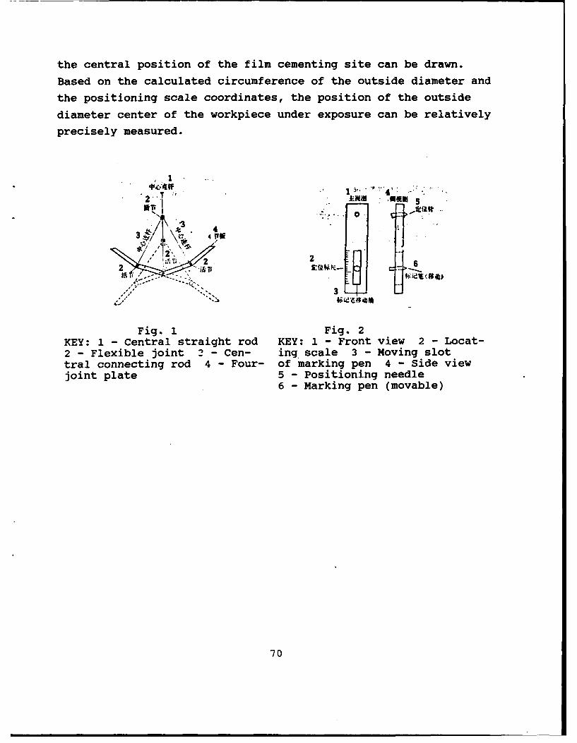
the central position of the film cementing site can be drawn.
Based on the calculated circumference of the outside diameter and
the positioning scale coordinates, the position of the outside
diameter center of the workpiece under exposure can be relatively
precisely measured.
2..T "' 1 ' 4 .. .
" ,T ' 0-' " . -3/ r. 4
V-2'i T .... o.. \e. z4
Fig. 1 Fig. 2KEY: 1 - Central straight rod KEY: 1 - Front view 2 - Locat-2 - Flexible joint 2 - Cen- ing scale 3 - Moving slottral connecting rod 4 - Four- of marking pen 4 - Side viewjoint plate 5 - Positioning needle
6 - Marking pen (movable)
70
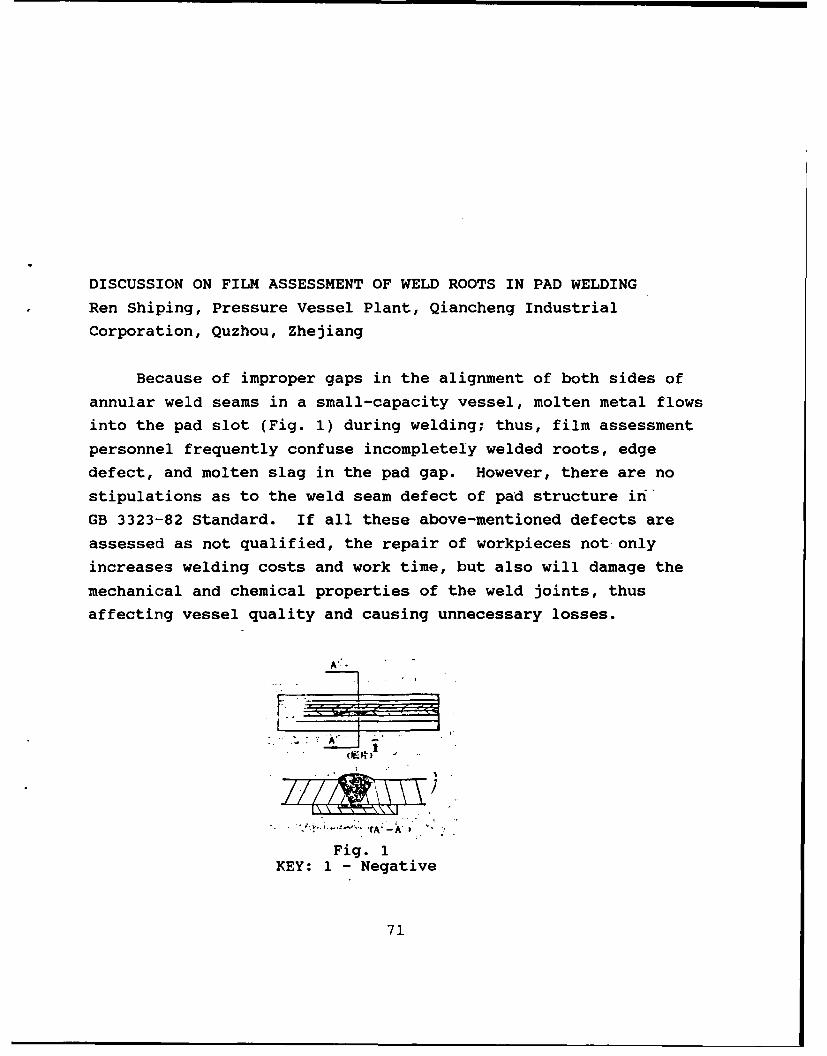
DISCUSSION ON FILM ASSESSMENT OF WELD ROOTS IN PAD WELDING
Ren Shiping, Pressure Vessel Plant, Qiancheng Industrial
Corporation, Quzhou, Zhejiang
Because of improper gaps in the alignment of both sides of
annular weld seams in a small-capacity vessel, molten metal flows
into the pad slot (Fig. 1) during welding; thus, film assessment
personnel frequently confuse incompletely welded roots, edge
defect, and molten slag in the pad gap. However, there are no
stipulations as to the weld seam defect of pad structure in
GB 3323-82 Standard. If all these above-mentioned defects are
assessed as not qualified, the repair of workpieces not only
increases welding costs and work time, but also will damage the
mechanical and chemical properties of the weld joints, thus
affecting vessel quality and causing unnecessary losses.
0E. )0
Fig. 1KEY: 1 - Negative
71
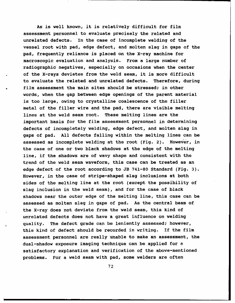
As is well known, it is relatively difficult for film
assessment personnel to evaluate precisely the related and
unrelated defects. In the case of incomplete welding of the
vessel root with pad, edge defect, and molten slag in gaps of the
pad, frequently reliance is placed on the X-ray machine for
macroscopic evaluation and analysis. From a large number of
radiographic negatives, especially on occasions when the center
of the X-rays deviates from the weld seam, it is more difficult
to evaluate the related and unrelated defects. Therefore, during
film assessment the main sites should be stressed; in other
words, when the gap between edge openings of the parent material
is too large, owing to crystalline coalescence of the filler
metal of the filler wire and the pad, there are visible melting
lines at the weld seam root. These melting lines are the
important basis for the film assessment personnel in determining
defects of incompletely welding, edge defect, and molten slag in
gaps of pad. All defects falling within the melting lines can be
assessed as incomplete welding at the root (Fig. 2). However, in
the case of one or two black shadows at the edge of the melting
line, if the shadows are of wavy shape and consistent with the
trend of the weld seam waveform, this case can be treated as an
edge defect of the root according to JB 741-80 Standard (Fig. 3).
However, in the case of stripe-shaped slag inclusions at both
sides of the melting line at the root (except the possibility of
slag inclusion in the weld seam), and for the case of black
shadows near the outer edge of the melting line, this case can be
assessed as molten slag in gaps of pad. As the central beam of
the X-ray does not deviate from the weld seam, this kind of
unrelated defects does not have a great influence on welding
quality. The defect grade can be leniently assessed; however,
this kind of defect should be recorded in writing. If the film
assessment personnel are really unable to make an assessment, the
dual-shadow exposure imaging technique can be applied for a
satisfactory explanation and verification of the above-mentioned
problems. For a weld seam with pad, some welders are often
72
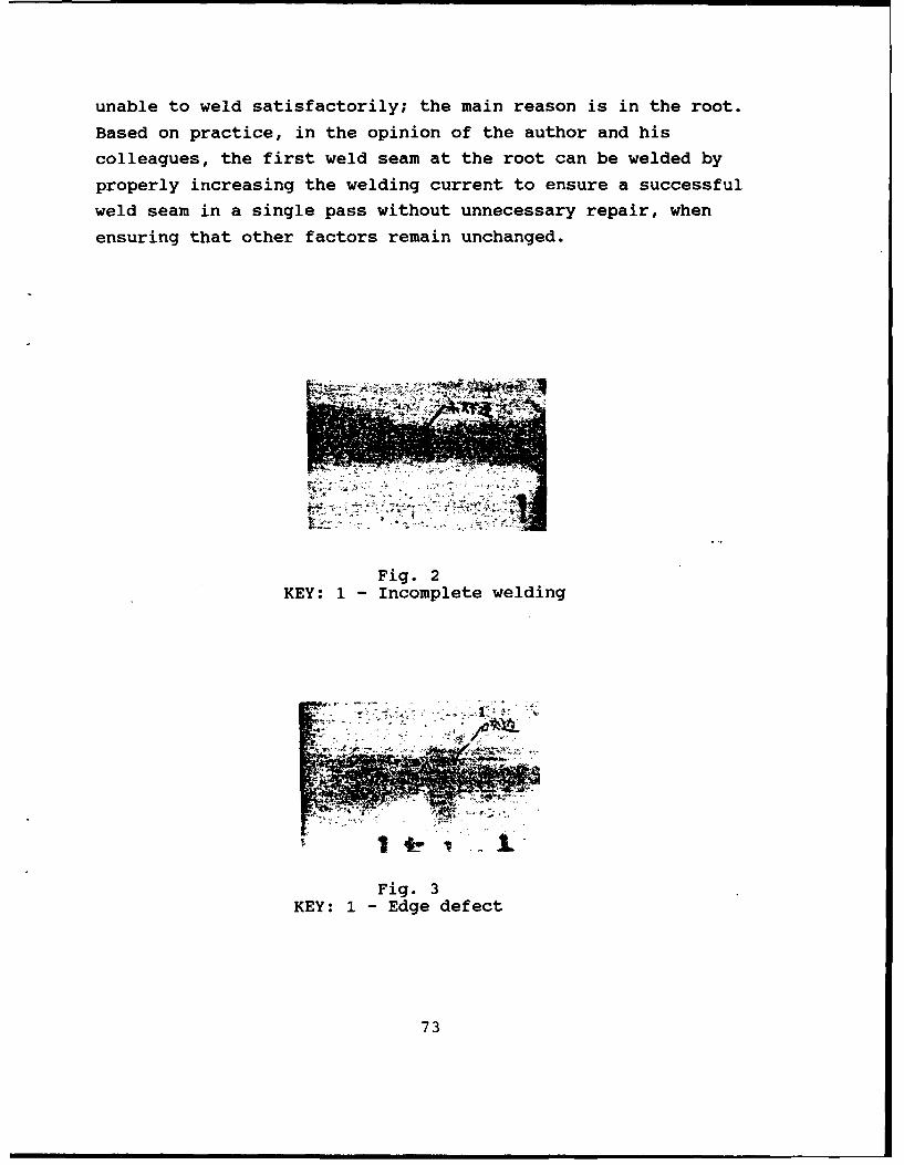
unable to weld satisfactorily; the main reason is in the root.
Based on practice, in the opinion of the author and his
colleagues, the first weld seam at the root can be welded by
properly increasing the welding current to ensure a successful
weld seam in a single pass without unnecessary repair, when
ensuring that other factors remain unchanged.
Fig. 2KEY: 1 - Incomplete welding
Fig. 3
KEY: 1 - Edge defect
73
RULES FOR QUALIFICATION AND CERTIFICATION OF NONDESTRUCTIVE TEST
PERSONNEL--CHINESE PEOPLE'S REPUBLIC STATE STANDARD GB 9445-88
I. Contents and Adaptation Range of Main Topic
This standard regulates the general principles and methods
of personnel grade classification, duty, certification of
technical qualification and issuing of certificates for the five
nondestructive test (NDT) methods of ultrasonics, radiography,
magnetic particles, permeability and eddy current.
This standard is adaptable to the NDT methods stipulated in
this standard for certification of the technical qualifications
of NDT personnel involved with industrial products, parts,
components, structural members, raw materials, and supplies, as
well as monitoring and examining of in-service equipment quality
and safety. This standard is also adaptable to technical
qualification certification by personnel administering
qualification examinations for on-duty NDT personnel.
No qualification certification is required according to the
technical standard on management personnel administering quality
and safety control in scientific research, teaching, instruments,
equipment and device production and state agencies on NDT
techniques.
74
Those personnel who have passed the qualification
certification examination are issued the Technical Qualification
Certificate for NDT Personnel by the administrative department
upon receiving a test report from the Qualifying Body. Only NDT
personnel who have received technical qualification certificates
can engage in NDT work at the corresponding grade and method as
specified in the certificate they hold.
. Technical Terms
Technical qualification is defined as the comprehension of
knowledge and technique required for correctly executing the NDT
mission, as well as experience and practice of NDT professional
training.
Certification of technical qualification indicates the
technical knowledge and capability of NDT personnel for
inspecting general or special examination objects by using a
certain NDT method, as well as the examination and certification
process of the technical qualification. After passing the
qualification test, these personnel are issued technical
qualification certificates.
The Qualifying Body is a nonprofit, fair-minded agency under
administrative departments; the body is responsible for execution
of technical qualification certification rules for NDT personnel.
The Qualifying Body authorizes a certain examination center for
handling such examinations.
By filing applications, applicants of NDT candidate request
by written application that they be given a qualification
certification examination according to the stipulations of this
standard.
75
Basic education is regular education recognized by the
administrative departments. Basic education is one of the
requirements for approved participation in qualifying
examinations for NDT personnel.
NDT training is the educational process of methodological
theory and practical capability of these applicants for NDT
personnel. By referring to the recommended teaching outline and
curriculum units, the applicants for NDT personnel qualifying
examination receive training. The test specimens and reference
blocks for exercises during training are not to be confused with
those in the NDT examination.
Practical experience is the cumulative time of the
qualifying examination applicants on certain NDT methods as their
main work. Such cumulative time should be evaluated and
approved. The personnel division of the examination applicants'
unit is responsible for evaluating the cumulative time of the
recorded practical experience.
NDT methods are certain methods of NDT applications in the
relevant physical principles; these methods in the standard
include ultrasonics, radiography, magnetic particle, permeability
and eddy current, among other methods.
NDT techniques are the concrete execution of certain NDT
stipulations on how to execute NDT methods in some NDT work
procedure. Generally, such techniques are described in the NDT
technical manual.
NDT procedures are documents that detail the where, when and
how of the examined product for NDT work.
At present, an industrial sector is the administrative
department of various production units of industrial products
76
under the State Council, as well as those units equivalent to the
level of ministry or commission of railroads, communications and
safety supervision.
General examination includes the basic knowledge that the
NDT personnel should master, the fundamental principle of a
certain NDT method, the basic inspection technique of general NDT
objects, as well as knowledge and practical experience of the
quality grade assessment standard. For NDT personnel of grade
III, the general examination includes basic knowledge on
materials, techniques and cause of defects, general awareness of
the articles of this standard and other NDT methods, as well as
practical experience of compiling general manuals of NDT
processes and techniques. The level of this examination should
be consistent among the various industrial departments.
An industry-specific examination is a supplementary
examination on the basis of a general examination as required by
an industrial department for specific reasons. Such an
examination includes the operation and calibration of specific
equipment used by the industrial department; specific procedures
of inspection techniques, specialized norms, standards and codes
as well as acceptance standards; and a compilation of specialized
NDT processes and a technical manual.
A general certificate of technical qualification is issued
to the NDT examination applicants who have passed the general
examination with qualification approval. Such a general
certificate should be recognized among various industrial
departments. Only those holding the general certificate of
technical qualification can go to the next step of taking part in
the industry-specific examination. However, for general
industrial NDT application departments, persons holding the
general certificate of technical qualification can engage in NDT
work of the corresponding grade and the corresponding NDT
77
methods.
An industry-specific certificate of technical qualification
is issued to those NDT examination applicants who have passed the
technical qualification industry-specific examination and with
qualification approval.
The form of the basic knowledge examination is a written
test with the following contents: general NDT knowledge and
theory (different depths for different grades), materials,
technical processes and causes of defects (for industrial
department with specific requirements, this means the knowledge
about materials, technical processes and causes of defects of the
particular industrial department), as well as the knowledge
relating to the rules of this standard. The examination contents
should be included in the general examination and the industry-
specific examination.
The methods examination is in the form of a written test
with the following contents; principle of a NDT method,
application and limitations of this method, equipment,
instrument, reference block, test specimen, use of test agents,
general methods, standards, norms and quality levels, as well as
ability in analyzing test results. For industrial departments
with specific requirements, the methods examination is the
supplementary contents of the special requirements relating to
the above mentioned contents.
The examination on practical ability is a test on practi.cal
operations for grades I and II by examining the applicants on
their general or specific operational technique and skillfulness
for a NDT method. For grade III personnel, the examination
covers their capability of compiling a general or specific NDT
technique and process manual in the form of a written test. In
addition, through the supplementary oral examination, their
78
practicing capability is examined. This kind of examination
contents should be included in both the general examination and
the industry-specific examination.
3. Classification of Technical Qualification Grades and
Technical Duty for NDT Personnel
3.1. Classification of technical qualification grades
There are the three following grades for technical
qualification of NDT personnel: grade III as the highest, grade
II as the intermediate, and grade I as the lowest. Qualification
certification is conducted on different grades and methods.
3.2. Technical duties of various grades of NDT personnel
3.2.1. Grade I NDT personnel should have the capability
under supervision and monitoring of grade II or III personnel to
conduct NDT work based on a technical manual, to calibrate and
use instruments, to conduct inspection operation, to record the
inspection results, and to make assessment of elementary grades
based on inspection results as stipulated in this standard.
3.2.2. Based on matured techniques, grade II NDT personnel
can compile a technical manual, install and calibrate instruments
and equipment, concretely carry out NDT work, illustrate and
evaluate inspection results based on code and standard, write and
sign reports on inspection results, master the adaptation range
and limitations of NDT methods, as well as train and supervise
grade I personnel and those not yet receiving any certificate.
3.2.3. Grade III NDT personnel should have all
responsibilities on determining NDT techniques and processes, on
executing stipulations in codes, norms and standards, in
supervising and monitoring the overall progress of NDT work, in
79
illustrating and evaluating the inspection results based on
codes, norms and standards, in having the capability of designing
specific NDT methods, techniques and processes, in assisting the
related technical departments to prescribe acceptance standard
when no acceptance standard can be applied, in mastering the
practical knowledge of materials, structure and production
technique, in mastering other NDT methods, as well as in training
grades I and II personnel.
I. Qualifying Body
4.1. Composition
The qualifying body should include representatives of the
administrative department, representatives of safety and quality
monitoring departments, and personnel appointed by the
administrative department and those issued grade III NDT
technical qualification certificates. Grade III NDT personnel
should be in the majority on the examining body.
4.2. Duties
4.2.1. The examining body compiles a Collection of General
Examination Questions, a Collection of Industry-Specific
Examination Questions, and Examination Rules on Practical
Operation Techniques, and makes reference blocks and specimens
for special examinations of the general or the administrative
industrial department.
4.;t.2. The examining body jointly establishes an examination
center with the administrative or other industrial department.
4.a.3. The body conducts a qualifying examination for grade
III NDT personnel.
80
4.2.4. Under the requirements of the rules in this standard,
the qualifying body organizes examination work for qualifying NDT
personnel below grade II of this administrative department. The
body authorizes and appoints examination organizations or units
for qualifying NDT personnel below grade II in this
administrative department.
4.2.5. The body approves the examination results of
qualifying grades II and I personnel of this administrative
department.
4.3. Examination center
An examination center can be authorized by the examining
body for its establishment and approval; the requirements of
examination center are as follows;
a. The center should have a sufficient number of working
personnel (who have been approved) as well as appropriate housing
and equipment facilities in order to ensure requirements of the
general examination and the industry-specific examination of NDT
personnel.
b. In various examination centers, the common examination
reference blocks and specimens should include comparative defect
types and kinds.
c. Based on requirements set by the examining body, the
examination center makes reference blocks and specimens for
examination; these blocks and specimens should be separated from
that used in training and exercise.
. Qualifications of Examination Applicants
5.1. General requirements
81
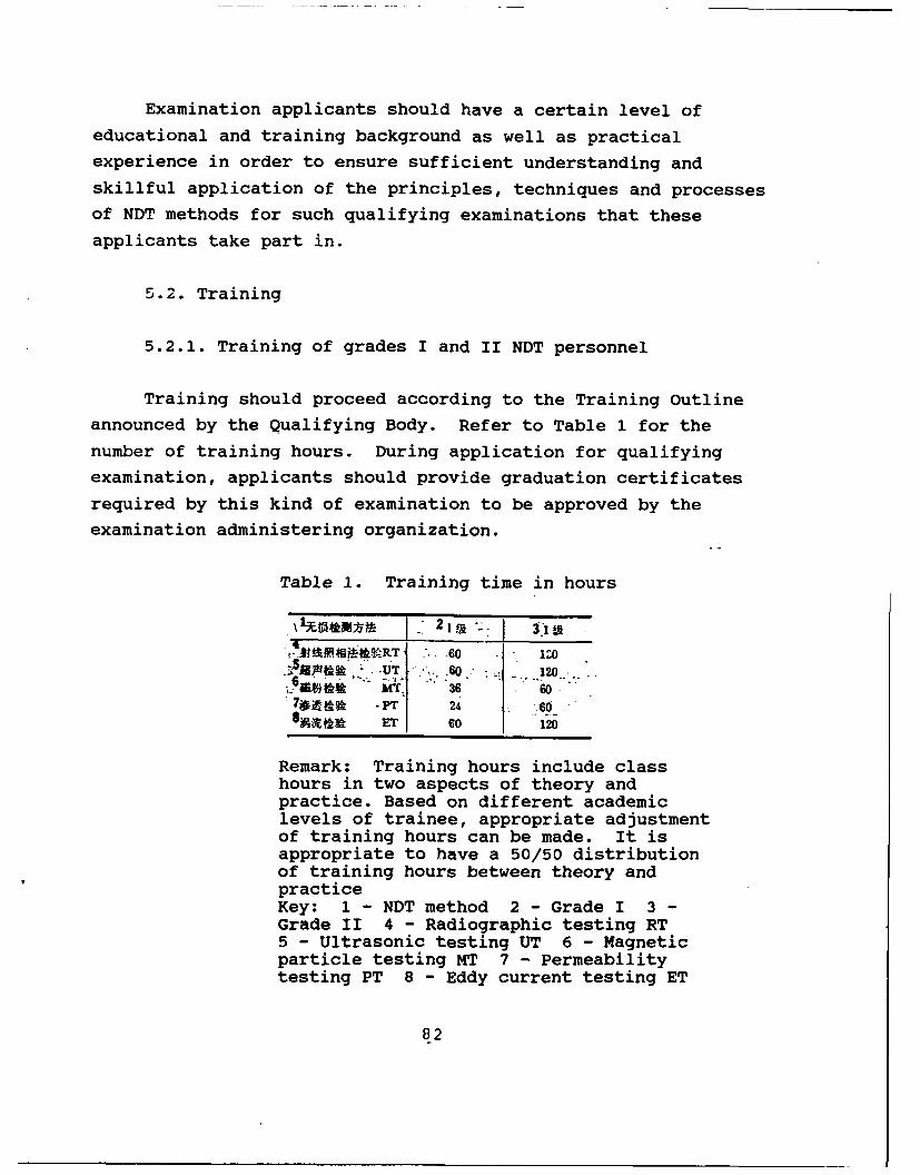
Examination applicants should have a certain level of
educational and training background as well as practical
experience in order to ensure sufficient understanding and
skillful application of the principles, techniques and processes
of NDT methods for such qualifying examinations that these
applicants take part in.
5.2. Training
5.2.1. Training of grades I and II NDT personnel
Training should proceed according to the Training Outline
announced by the Qualifying Body. Refer to Table 1 for the
number of training hours. During application for qualifying
examination, applicants should provide graduation certificates
required by this kind of examination to be approved by the
examination administering organization.
Table 1. Training time in hours
.0 .60 :* UT.'60 120.
iW* MT- 36 607wi tk -p 24 68AR ET 60 120
Remark: Training hours include classhours in two aspects of theory andpractice. Based on different academiclevels of trainee, appropriate adjustmentof training hours can be made. It isappropriate to have a 50/50 distributionof training hours between theory andpracticeKey: 1 - NDT method 2 - Grade I 3 -
Grade II 4 - Radiographic testing RT5 - Ultrasonic testing UT 6 - Magneticparticle testing MT 7 - Permeabilitytesting PT 8 - Eddy current testing ET
82
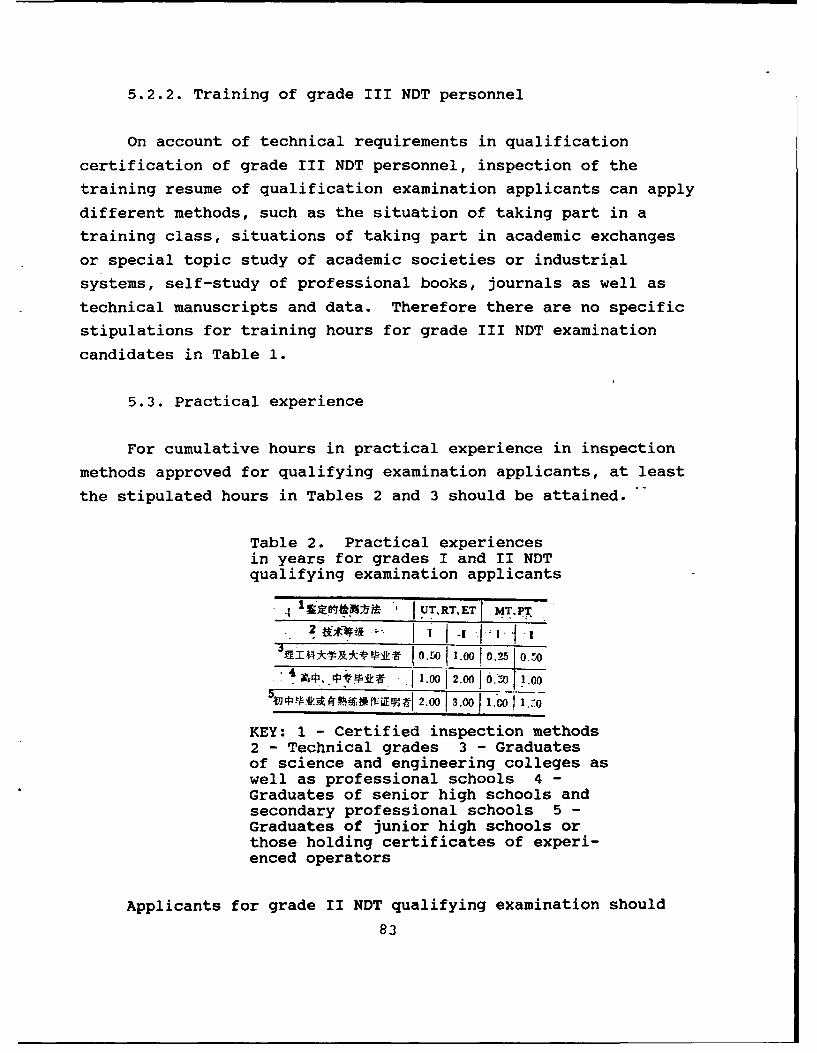
5.2.2. Training of grade III NDT personnel
On account of technical requirements in qualification
certification of grade III NDT personnel, inspection of the
training resume of qualification examination applicants can apply
different methods, such as the situation of taking part in a
training class, situations of taking part in academic exchanges
or special topic study of academic societies or industrial
systems, self-study of professional books, journals as well as
technical manuscripts and data. Therefore there are no specific
stipulations for training hours for grade III NDT examination
candidates in Table 1.
5.3. Practical experience
For cumulative hours in practical experience in inspection
methods approved for qualifying examination applicants, at least
the stipulated hours in Tables 2 and 3 should be attained.
Table 2. Practical experiencesin years for grades I and II NDTqualifying examination applicants
S1 I UTRT.ET MT.PT
I_________vv___t _ 0.50_1.0010.25 0
*. 4 1 --P.74k . .1.0012.00 1 6Z0 1.00
'b PA VA M M i CV_12.00 1_.0_6_ .7-
KEY: 1 - Certified inspection methods2 - Technical grades 3 - Graduatesof science and engineering colleges aswell as professional schools 4 -Graduates of senior high schools andsecondary professional schools 5 -Graduates of junior high schools orthose holding certificates of experi-enced operators
Applicants for grade II NDT qualifying examination should
83
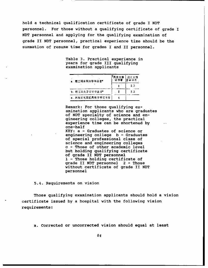
hold a technical qualification certificate of grade I NDT
personnel. For those without a qualifying certificate of grade I
NDT personnel and applying for the qualifying examination of
grade II NDT personnel, practical experience time should be the
summation of resume time for grades I and II personnel.
Table 3. Practical experience inyears for grade III qualifyingexamination applicants
b.~f ISS 12 f 44f-I 2.3
b. 2 3.
Remark: For those qualifying ex-amination applicants who are graduatesof NDT specialty of science and en-gineering colleges, the practicalexperience time can be shortened byone-halfKEY: a - Graduates of science orengineering college b - Graduatesof special professional class ofscience and engineering collegesc - Those of other academic levelbut holding qualifying certificateof grade II NDT personnel1 - Those holding certificate ofgrade II NDT personnel 2 - Thosewithout certificate of grade II NDTpersonnel
5.4. Requirements on vision
Those qualifying examination applicants should hold a vision
certificate issued by a hospital with the following vision
requirements:
a. Corrected or uncorrected vision should equal at least
84
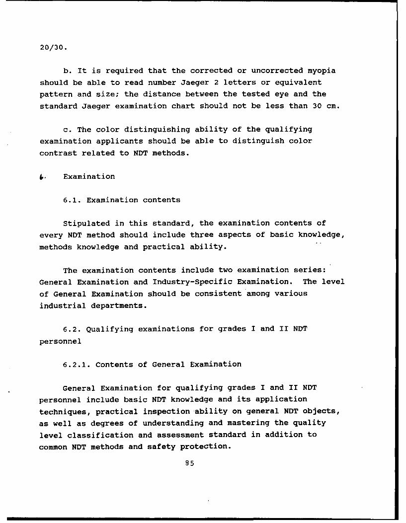
20/30.
b. It is required that the corrected or uncorrected myopia
should be able to read number Jaeger 2 letters or equivalent
pattern and size; the distance between the tested eye and the
standard Jaeger examination chart should not be less than 30 cm.
c. The color distinguishing ability of the qualifying
examination applicants should be able to distinguish color
contrast related to NDT methods.
Examination
6.1. Examination contents
Stipulated in this standard, the examination contents of
every NDT method should include three aspects of basic knowledge,
methods knowledge and practical ability.
The examination contents include two examination series:
General Examination and Industry-Specific Examination. The level
of General Examination should be consistent among various
industrial departments.
6.2. Qualifying examinations for grades I and II NDT
personnel
6.2.1. Contents of General Examination
General Examination for qualifying grades I and II NDT
personnel include basic NDT knowledge and its application
techniques, practical inspection ability on general NDT objects,
as well as degrees of understanding and mastering the quality
level classification and assessment standard in addition to
common NDT methods and safety protection.
85
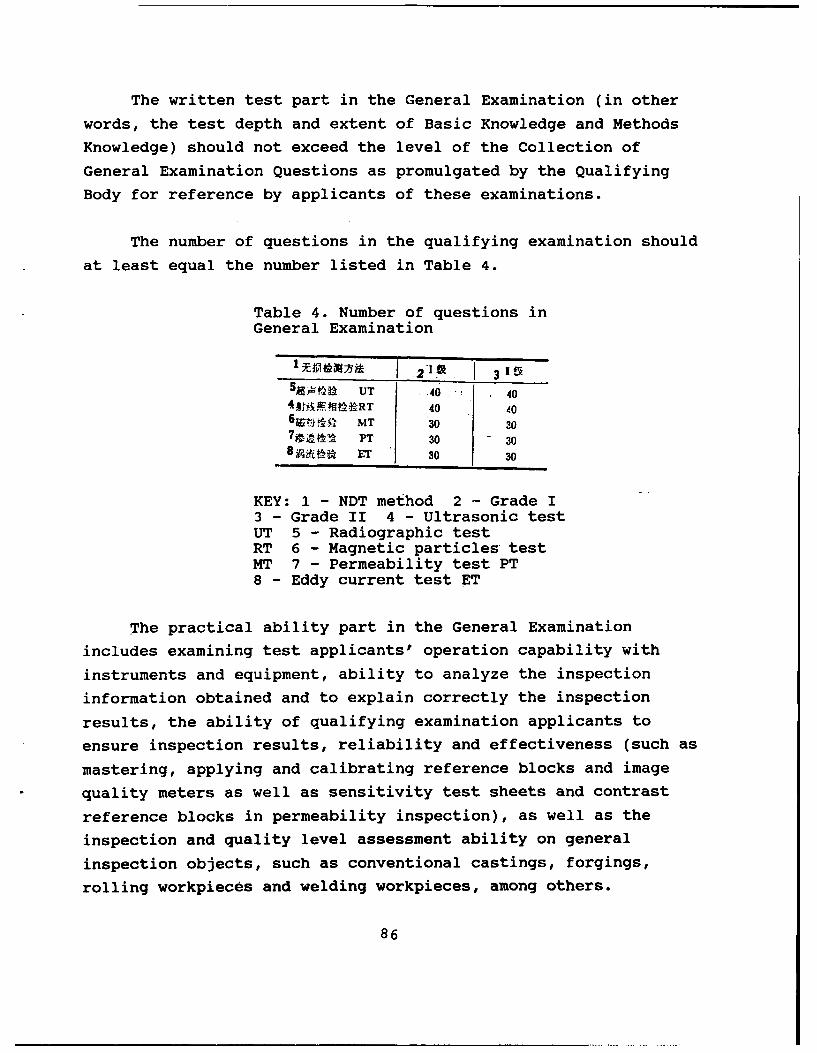
The written test part in the General Examination (in other
words, the test depth and extent of Basic Knowledge and Methods
Knowledge) should not exceed the level of the Collection of
General Examination Questions as promulgated by the Qualifying
Body for reference by applicants of these examinations.
The number of questions in the qualifying examination should
at least equal the number listed in Table 4.
Table 4. Number of questions inGeneral Examination
5 t UT 4 404 A t, RT 40 40
6e MT 30 307p PT 30 308 "ET 30 30
KEY: 1 - NDT method 2 - Grade I3 - Grade II 4 - Ultrasonic testUT 5 - Radiographic testRT 6 - Magnetic particles testMT 7 - Permeability test PT8 - Eddy current test ET
The practical ability part in the General Examination
includes examining test applicants' operation capability with
instruments and equipment, ability to analyze the inspection
information obtained and to explain correctly the inspection
results, the ability of qualifying examination applicants to
ensure inspection results, reliability and effectiveness (such as
mastering, applying and calibrating reference blocks and imagequality meters as well as sensitivity test sheets and contrast
reference blocks in permeability inspection), as well as the
inspection and quality level assessment ability on general
inspection objects, such as conventional castings, forgings,
rolling workpieces and welding workpieces, among others.
86
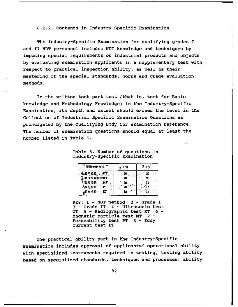
6.2.2. Contents in Industry-Specific Examination
The Industry-Specific Examination for qualifying grades I
and II NDT personnel includes NDT knowledge and techniques by
imposing special requirements on industrial products and objects
by evaluating examination applicants in a supplementary test with
respect to practical inspection ability, as well as their
mastering of the special standards, norms and grade evaluation
methods.
In the written test part test (that is, test for Basic
knowledge and Methodology Knowledge) in the Industry-Specific
Examination, its depth and extent should exceed the level in the
Collection of Industrial Specific Examination Questions as
promulgated by the Qualifying Body for examination reference.
The number of examination questions should equal at least the
number listed in Table 5.
Table 5. Number of questions inIndustry-Specific Examination
13E O-" .... Ii 31.20 _20~ ~4~A~RT 20 2
6a~.r XT -20 15
A f.i T15.,15
KEY: 1 - NDT method 2 - Grade I3 - Grade II 4 - Ultrasonic testUT 5 - Radiographic test RT 6 -Magnetic particle test MT 7 -Permeability test PT 8 - Eddycurrent test ET
The practical ability part in the Industry-Specific
Examination includes approval of applicants' operational ability
with specialized instruments required in testing, testing ability
based on specialized standards, techniques and processes; ability
87
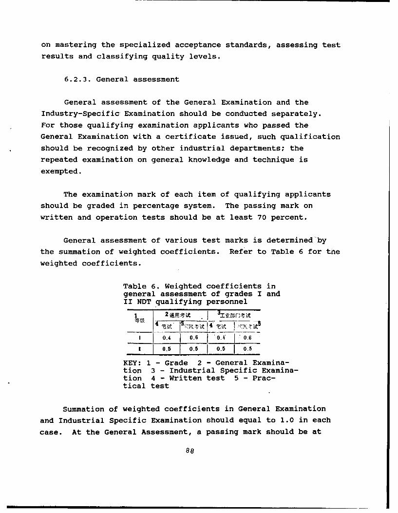
on mastering the specialized acceptance standards, assessing test
results and classifying quality levels.
6.2.3. General assessment
General assessment of the General Examination and the
Industry-Specific Examination should be conducted separately.
For those qualifying examination applicants who passed the
General Examination with a certificate issued, such qualification
should be recognized by other industrial departments; the
repeated examination on general knowledge and technique is
exempted.
The examination mark of each item of qualifying applicants
should be graded in percentage system. The passing mark on
written and operation tests should be at least 70 percent.
General assessment of various test marks is determined by
the summation of weighted coefficients. Refer to Table 6 for the
weighted coefficients.
Table 6. Weighted coefficients ingeneral assessment of grades I andII NDT qualifying personnel
1 0.4 0.6 i0o.- A
1 0.5 0.5 1 0.5 0.5
KEY: 1 - Grade 2 - General Examina-tion 3 - Industrial Specific Examina-tion 4 - Written test 5 - Prac-tical test
Summation of weighted coefficients in General Examination
and Industrial Specific Examination should equal to 1.0 in each
case. At the General Assessment, a passing mark should be at
88
least 80 percent.
6.3. Qualifying examination for grade III NDT personnel
6.3.1. The qualifying examination for grade III NDT
applicants is in written form. In addition, verification of
applicants' technical qualification and an oral test on technical
capability should be conducted.
6.3.2. Contents in General Examination
6.3.2.1. Basic Knowledge (Only one test is required when
verifying several methods)
a. Five examination questions related to the contents of
this rule.
b. Fifteen examination questions related to knowledge'of
common materials, strength of materials, product manufacturing
process, defect property and defect causative mechanism.
c. Twenty examination questions corresponding to the level
of the Collection of General Examination Questions for qualifying
grade II NDT personnel of four other NDT methods thus
promulgated.
6.3.2.2. Methods knowledge
a. Thirty examination questions with a level corresponding
to the Collection of General Examination Questions thus
promulgated for grade III personnel on NDT methods; and
b. Ten examination questions on ability in explaining the
related codes, standards and technical norms for NDT methods.
89
6.3.2.3. Practical ability
It is required that the qualified (from the examination) NDT
personnel have the ability of compiling NDT process and technical
manual for conventional test objects. For applicants of the
qualifying examination not yet having a grade II qualification
certificate, they should be tested additionally on practical
operational techniques of this NDT method.
6.3.3. Contents in Industry-Specific Examination
6.3.3.1. Twenty examination questions corresponding to the
level of the Collection of Examination Questions on Methods
Knowledge in the NDT test of Basic Knowledge for grade III
personnel required by the specific industrial department and
promulgated by the Qualifying Body. The range of such
examination questions include the manufacturing technique of
special materials and products used by the specific industrial
department, defect property, defect causative mechanism, as well
as the specific norms, standards and codes of NDT method that the
qualifying examination applicants requested in addition to the
specific inspecting instruments, methods, techniques and
processes.
6.3.3.2. In the Industry-Specific Examination, it is
required in the Practical Ability test of grade III NDT
qualifying personnel with the ability of compiling an NDT process
and a technical manual on specific test objects of the industrial
department. For such qualifying examination applicants not yet
obtaining a grade II technical qualification certificate of the
administrative industrial department, an additional test is
required on the practical operational technique of the NDT
method.
6.3.4. General Assessment
90
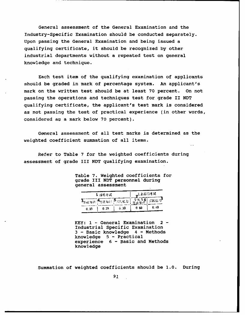
General assessment of the General Examination and the
Industry-Specific Examination should be conducted separately.
Upon passing the General Examination and being issued a
qualifying certificate, it should be recognized by other
industrial departments without a repeated test on general
knowledge and technique.
Each test item of the qualifying examination of applicants
should be graded in mark of percentage system. An applicant's
mark on the written test should be at least 70 percent. On not
passing the operations and techniques test for grade II NDT
qualifying certificate, the applicant's test mark is considered
as not passing the test of practical experience (in other words,
considered as a mark below 70 percent).
General assessment of all test marks is determined as the
weighted coefficient summation of all items.
Refer to Table 7 for the weighted coefficients during
assessment of grade III NDT qualifying examination.
Table 7. Weighted coefficients forgrade III NDT personnel duringgeneral assessment
0. 35 I0. 35 (130 0.60 0.40
KEY: 1 - General Examination 2 -
Industrial Specific Examination3 - Basic knowledge 4 - Methodsknowledge 5 Practicalexperience 6- Basic and Methodsknowledge
Summation of weighted coefficients should be 1.0. During
91
general assessment, the passing mark of qualifying examination
applicants should be at least 80 percent. If doubts are raised
on technical qualification and experience during an oral test of
the qualifying applicants, a written opinion is filed after an
evaluation meeting by the Qualifying Body.
6.4. Supplementary test and repeated test
In the two- and three-item test of General-Examination or
the Industry-Specific Examination (two-item test of Basic and
Methods Knowledge and Practical Experience for grades I and II
NDT qualifying test; three-item test of Basic Knowledge, Methods
Knowledge and Practical Experience in the General Examination of
grade III NDT qualification; and two-item test of Basic and
Methods Knowledge and Practical Experience in grade III NDT
qualifying examination), all marks are over 70 percent but the
General Assessment mark is lower than 80 percent (not passed),
the items with marks lower than 80 percent are allowed a
supplementary test within a year. If the General Assessment mark
is still lower than 80 percent after the supplementary test, all
items should be repeatedly tested.
Those applying for a repeated test should file for the test
according to the sequence of test applications.
If not approved in qualification for qualifying applicants,
they can take part in a repeated test only after two months. If
corruption and dishonesty are discovered in the qualifying test,
such applicants can apply for a repeated test only after two
years.
71 Certificate
7.1. Issuing of certificate
92
For those with a passing mark in the examination and with
approved qualification evaluation, certificates are issued by the
administrative department upon receiving a report from the
Qualifying Body.
7.2. Form of certificate
Refer to Annex A (supplement) for the form of certificate,
which was filled with details by the certificate issuing unit.
At the right lower corner of the personal photograph of
certificate holder, the certified NDT methods and grades of
technical qualification are prin-id for the certificate holder
along with stamped seal and signature of the responsible person
of the Qualifying Body; certificate issuing date and effective
period are also printed. For extension of effective date of the
certificate, a special extension seal of the Qualifying Body
should be stamped. Number should be filled on a certificate
based on stipulations of file management.
7.3. When a certified NDT personnel is traisferred from an
industrial department to another, the second department should
recognize the personnel's marks in the General Examination, and
his general technical qualification.
* Effective Period and Its Extended Effective Period of
Certificate
8.1. Effective period
The effective period of a certificate is at most five years
beginning from the issuing date.
In the following situations, the certificate should be
revoked and cancelled:
93
a. The certificate holder is a person deprived of political
rights.
b. The certificate holder made a major mistake in NDT
specialty work.
c. The certificate holder left his unit of NDT work for more
than a year.
8.2. Extension of effective period
At the end of an effective period, the Qualifying Body makes
a recheck on the certificate holder. When the holder's provided
proof is verified, another effective period of the certificate
can be extended. Upon filing for extension of the effective
period, the holder should provide the following proofs issued by
the personal division of his work unit:
a. Proof of passed physical checkup; and
b. Proof that the certificate holder did not leave NDT work
for more than a year.
j, Renewal Certification
9.1. At the end of the second extension period, the
certificate holder should file with the Qualifying Body for a
renewal certification. Upon approval of the renewal
certification, the old certificate holder is issued a new
extended period certificate. Those filing for renewal
certification should provide the two above-mentioned proofs for
extension of the effective period.
9.2. Renewal certification test
94
This is a simplified test approved by the Qualifying Body
with the following contents:
a. For grades I and II NDT personnel, the operation test
covers the general basic and the necessary industrial department
according to the simplified stipulations.
b. For grade III personnel, a written test of applied
technical knowledge is conducted with 20 test questions of
general basic or of the necessary industrial department.
If the test mark is over 60 percent, the renewal
certification is passed with issuing of a new effective date
proof.
/0OFile
The Qualifying Body should maintain the following files:
10.1. A registration chart should be filed by the personnel
to be certified according to different grades, different NDT
methods and different departments for classification.
10.2. For the personal file of each personnel to be
certified, and for each personnel whose certificate is revoked,
the following contents should be included:
a. Test data: test questions the personnel answered,
operation records and documents, written NDT process and
technical manual, and test grade report card;
b. Proofs for extending the effective period and renewing
certification; and
c. Other necessary materials that are required to maintain.
95
ANNEX A: FORM OF TECHNICAL QUALIFICATION CERTIFICATE FOR NDT
PERSONNEL (SUPPLEMENT)
Al. Composition of Qualifying Certificate
The qualification certificate is composed of three parts:
jacket, cover and core. The cover and core is bound together
with thread.
A2. Plastic Jacket
A2.1. Dimensions of the plastic jacket are 166x112 mm. The
front surface is printed with golden letters; there are two
pockets in the back of the jacket. Spacing of pocket openings is
26 mm (refer to Figs. Al and A2).
A2.2. The material for the front surface of the plastic
jacket is made of colored plastic fabric; selection of colors is
as follows:
a. Red for grade III certificate;
b. Sky blue for grade II certificate; and
c. Deep green for grade I certificate.
A2.3. Material for the pocket at back of the plastic jacket
is of colorless, transparent plastic film.
A3. Cover
A3.1. Dimensions of the cover are 152x104 mm; the cover is
made of soft lining paper (refer to Fig. A3).
96
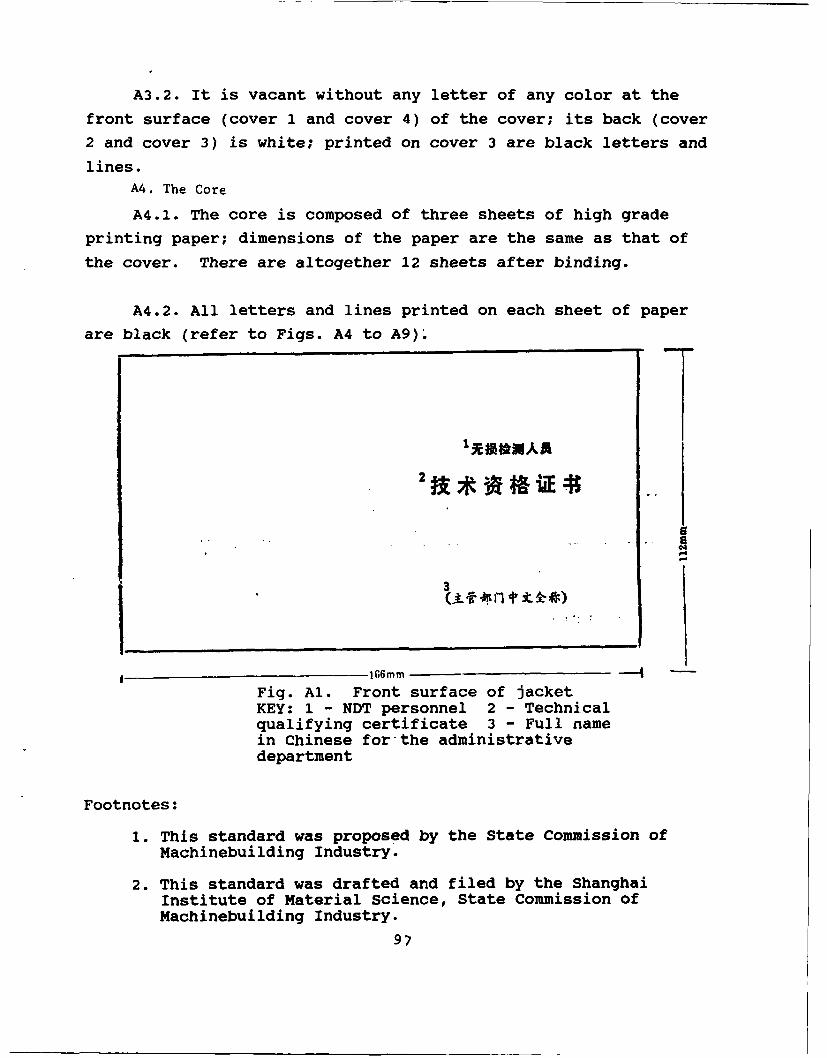
A3.2. It is vacant without any letter of any color at the
front surface (cover 1 and cover 4) of the cover; its back (cover
2 and cover 3) is white; printed on cover 3 are black letters and
lines.
A4. The Core
A4.1. The core is composed of three sheets of high grade
printing paper; dimensions of the paper are the same as that of
the cover. There are altogether 12 sheets after binding.
A4.2. All letters and lines printed on each sheet of paper
are black (refer to Figs. A4 to A9).
a
3
166mm -- 4
Fig. Al. Front surface of jacketKEY: 1 - NDT personnel 2 - Technicalqualifying certificate 3 - Full namein Chinese for the administrativedepartment
Footnotes:
1. This standard was proposed by the State Commission ofMachinebuilding Industry.
2. This standard was drafted and filed by the ShanghaiInstitute of Material Science, State Commission ofMachinebuilding Industry.
97
MODELS SD-I AND SD-IA IRIDIUM192 GAMMA-RAY FLAW DETECTING MACHINE
Iridium19 2 gamma-ray flaw detection machines are
manufactured by this factory licensing an imported advanced
technique from abroad. This kind of flaw detection machine was
certified by the former Ministry of Hydroelectric Power; the
manufacture of these machines is monitored by the Institute of
Electric Power Construction of the Ministry of Energy.
Maximum capacities: for model I, iridium19 2 , 60 curies; for
model IA, iridium19 2, 100 curies;
exposure range: 10 to 100mm for steel products, and±300mm
for concrete;
focus of radiation source: outside diameter 2x2, outside
diameter 2 x 3, outside diameter 3 x 3;
leakage dose: meets the international standard ISO 3999;
methods of transmitting radiation source: manual and
automatic;
operating distance: 15 to 18mm;
length of radiation source output: 5 to 8m;
98
weight: 15kg for model I, and 20kg for model IA; and
dimensions of the vessel: for model I, 290x11Omm; for
model IA, 290x118mm.
The automatic control attachment has the functions of time
delay start, automatic output of radiation source, exposure with
timer, automatic return, and manual control in the case of
malfunctioning or power loss, among other functions.
This factory applied the coordination of the machine
radiation source and the radiation source changer for ensuring
user demand by periodic supply of the radiation source. The
following items of equipment are attached to the machine: dosage
monitoring instrument, gamma-ray exposure calculating rule, and
protective clothing. In addition, this factory provides the
following services for users: on-site instruction, on-site
maintenance and repair, as well as recovery of waste radiation
source, among other services. Purchases are welcomed either with
written letter or dispatching of purchasing agent to the plant.
In addition, this plant provides the following products to
users:
SD143-85 single-wire exposure meter; SD143-85 defect depth
measuring meter; SD143-85 slot depth measuring meter;'GB5618-85
linear model quality meter; GB3323-87 equal-diameter image
quality meter; GB3323-87 standard film evaluation rule; as well
as GB3323-87 and SD143-85 film evaluation observation rule; film
cementing frame; enhancement screen; protection plate; ordinary
and multifunction dark boxes; and high-polymer lead equivalent
protection plate.
Haimen Flaw Detection Consortium Plant, Institute of
Electric Power Construction, Ministry of Energy
99
Plant site: Sanyang Town (chen), Halimen, Jiangsu; plant
superintendent: Xing Fei;
Telephone: Haimen 3644x59; Telegram: 4226
100
DILMyrCI LTST
DISTR1IBUXIrI DIRE~r 10 RXEI
C510 R&T IABS/AVEkDaCK 1C513 ARADOX4 IC535 A 'VRADOVTSAOC1 1C539 7RASAM 1
4. Q591 FSM1 4Q619 1MSIC METW~2E 1Q008 NTIC 1BD53 H;2~ USAF/NU7 1E404 AEDC/DOF 1E408 AFWL 1E410 AD/ID 1F429 SD/fl4D 1
P050 CA/0C/AMO/SD 2AFIT/ILE 1NoIC/oic-9 1c:v 1
MIA/TYS 1UffI/OCE L-309 1
ASD/FIV/ITA 1FSL 1
FTP- ID(PS)T-0356-90