Embed Size (px)
Citation preview
AD-A1A? 095 DAYTON UNIV OH RESEARCH INST FG/10FINITE ELEMENT TECHNIQUES FOR STATIC STRESS AND FREE VIRRATION ETC(U)MAR al _R_ A BROCE(MAN F33615 77-C 3075
UNCLASSIFIED UDR-TR 0-134 AFWAL-TR-81-3007 ML
1l1 -- --
1Il I 11 .8
MI(ROCO)PY RISIUDTION I|II (HARI
AFWAL-TR-81-3007 L V Lv ,
FINITE ELEMENT TECHNIQUES FOR STATIC STRESS AND FREE
OVIBRATION ANALYSIS OF SANDWICH COMPOSITES
R. A. Brockman
University of DaytonResearch InstituteDayton, Ohio 45469
March 1981
DTICELECTEP
NOV 01981 '
Final Report for Period September 1977 - November 1980 E
Approved for public release; distribution unlimited.
FLIGHT DYNAMICS LABORATORY
AIR FORCE WRIGHT AERONAUTICAL LABORATORIES
SAIR FORCE SYSTEMS COMMAND
WRIGHT-PATTERSON AIR FORCE BASE, OHIO 45433
81 11 10 070
NOTICE
When Government drawings, specifications, or other data areused for any purpose other than in connection with a definitelyrelated Goverment procurement operation, the United StatesGovernment thereby incurs no responsibility nor any obligationwhatsoever; and the fact that the government may have formulated,furnished, or in any way supplied the said drawings, specifications,or other data, is not to be regarded by implication or otherwiseas in any manner licensing the holder or any other person orcorporation, or conveying any rights or permission to manufactureuse, or sell any patented invention that may in any way berelated thereto.
This report has been reviewed by the Office of PublicAffairs (ASD/PA) and is releasable to the National TechnicalInformation Service (NTIS). At NTIS, it will be available to thegeneral public, including foreign nations.
This technical report has been reviewed and is approved forpublication.
HAROLD C. CROOP, AFWAL/FIBC LARRY C. i*LLY, Chief,'Project Engineer Structu V Concepts Bra
FOR THE COMMANDER
JAMES &A SEN, Assistant forResea h & TechnologyStructures and Dynamics Divis on
"If your address has changed, if you wish to be removedfrom our mailing list, or if the addressee is no longer employedby your organization please notify AFWAL/FIBC, WPAFB, Ohio, 45433,to help us maintain a current mailing list".
Copies of this report should not be returned unless returnis required by security considerations, contractual obligations,or notice on a specific document.
UnclassifiedSECURITY CLASSIFICATION OF THIS PAGE (ften Dae Enteted)_
READ INSTRUCTIONSEPORT DOCUMENTATION PAGE BEFORE COMPLETING FORM12. GOVT ACCESSION NO S. RECIPIENT'S CATALOG NUMBER
AFWAT TR-81-3$-0L4 .... . ... ... . ...... . -- 5.. slr,-":, SvW. 4U • W ~ v ... L ,
FINITE XLEMENT ECHNIQUES FOR STATIC 7 inal et.SepITRESS AND ;REE IBRATION hNALYSIS OF 77 OVSANDWICH COMPOSITES, . .R-TR- .-3
7. AUTHOR(*). N OR GRANT NUMBER(s)
obert A.iBrockman '2? F33615-77-C-675
9 PERFORMING ORGANIZATION NAME AND ADDRESS 10. PROGRAM ELEMENT. PROJECT, TASKUniversity of Dayton Research Institute AREA WORK UNIT NUMBERS
300 College Park Avenue 7- --4An 03/11 --- "Dayton, Ohio 45469
II. CONTROLLING OFFICE NAME AND ADDRESS
Air Force Wright Aeronautical Laboratori ar 817AFWAL/FIBCB NUMBEROF PAGWright-Patterson Air Force Base, OH 45433 6114. MONITORING AGENCY NAME & ADORESS(il different from Controlling Office) 15. SECURITY CLASS. 0o this report)
Unclassified
1Sa. DECL ASSIFIC ATION/DOWNGRADINGSCHEDULE
IS. DISTRIBUTION STATEMENT (of this Report)
Approved for public release; distribution unlimited.
17. DISTRIBUTION STATEMENT (of the abstract entered in Block 20, It different from Report)
IS. SUPPLEMENTARY NOTES
19. KEY WORDS (Continue on reverse side if neceseary and identify by block number) "
Sandwich Composites Thin ShellsFinite Element Method Thermal StressStiffened PanelsVibration Analysis
20. ABSTR,)X Contnue on reveree side If necessary and Identify by block number)
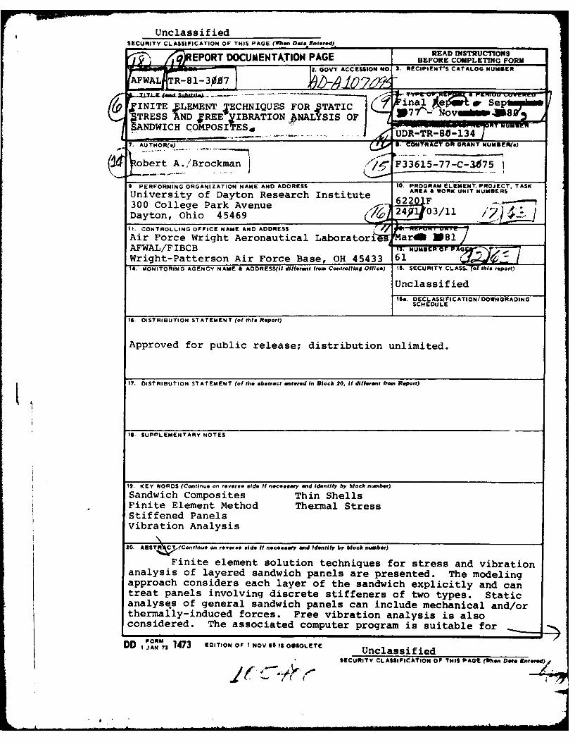
Finite element solution techniques for stress and vibrationanalysis of layered sandwich panels are presented. The modelingapproach considers each layer of the sandwich explicitly and cantreat panels involving discrete stiffeners of two types. Staticanalyses of general sandwich panels can include mechanical and/orthermally-induced forces. Free vibration analysis is alsoconsidered. The associated computer program is suitable for
ORM
DD JAN,3 1473 EDITION OF I NOV el IS OBSOLETE UnclassifiedSECURITY CLASSIFICATION OF THIS PAGE (len Doef Entered)
_ _ - - n i . .. . n i. . .II . .. " : -- ,. ii i . .. . .. . . . . . . ll~ ...k 0 I
+ llT ne Am tan i f ie=d8GUIMITY CLASSIFICATION OF THIS PAOGC(uhn Os4a SIaorIs
20. (continued)
toperation at an interactive terminal, and includes provisions forautomatic mesh generation and tabular output. Generated inputand output data are in a form which may be accessed by existingcomputer graphics programs for plotting geometry and results.Sample analyses are presented to demonstrate the developedtechniques.
UnclassifiedSECURITY CLASSI*ICATIOls OF Tw- PAOnl~hefl Date Entemo.)
FOREWORD
This report describes work performed by the University of
Dayton Research Institute (UDRI) under Air Force Contract
F33615-77-C-3075, Structural Sandwich Composites. The effort
was conducted for the Flight Dynamics Laboratory, Air Force
Wright Aeronautical Laboratories, under the administration and
technical direction of the Air Force Project Engineer,
Mr. Harold C. Croop (AFWAL/FIBCB).
Administrative project supervision at the UDRI was
provided by Mr. Dale H. Whitford (Supervisor, Aerospace
Mechanics Division), and technical supervision was provided by
Dr. Fred K. Bogner (Group Leader, Analytical Mechanics Group).
!A cce,:sion For'
IH
iiii
TABLE OF CONTENTS
SECTION PAGE
1 INTRODUCTION 1
1.1 GENERAL APPROACH 1
1.2 SCOPE OF ANALYSIS 2
2 THEORETICAL FORMULATION 4
2.1 THIN SHELL/FACE SHEET ELEMENTS 4
2.2 SANDWICH CORE ELEMENTS 10
2.3 FACE SHEET AND FULL-DEPTH STIFFENERS 12
3 NUMERICAL SOLUTION TECHNIQUES 18
3.1 LINEAR STATIC ANALYSES 18
3.2 NATURAL FREQUENCY SOLUTION 19
4 COMPUTER PROGRAM DESCRIPTION 22
4.1 PROGRAM FUNCTIONS AND ORGANIZATION 22
4.2 INTERACTIVE OPERATION 22
5 SAMPLE ANALYSES 27
5.1 STATIC ANALYSIS WITH MECHANICAL ANDTHERMAL LOADS 27
5.2 NATURAL FREQUENCY ANALYSIS 29
6 SUMMARY AND CONCLUSIONS 34
APPENDIX: SAMPLE INTERACTIVE TERMINAL SESSION 35
REFERENCES 55
V4 - -
Pk~LhJ.~~O ~2 bLIF~m~t
a
LIST OF ILLUSTRATIONS
FIGURE PAGE
1 Undeformed Geometry of a Shell Element 6
2 Trilinear Shell Finite Element 11
3 Sandwich Core Finite Element 13
4 Face Sheet and Full-Depth Stiffeners 14
5 Stiffener Finite Element in Local Coordinates 17
6 Computer Program Organization 23
7 Clamped Panel Under Uniform Pressure 28
8 Deformed Geometry of Square Panel Under Anti-symmetric Thermal Loading 30
9 Core Shear Stresses for Sandwich Pnael withAntisymmetric Temperature Distribution 31
10 Sandwich Panel for Natural Frequency Analysis 32
vi
SECTION 1I NTRODUCTION
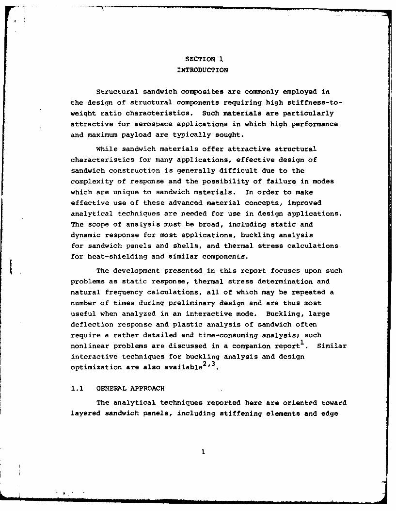
Structural sandwich composites are commonly employed in
the design of structural components requiring high stiffness-to-
weight ratio characteristics. Such materials are particularly
attractive for aerospace applications in which high performanceand maximum payload are typically sought.
While sandwich materials offer attractive structural
characteristics for many applications, effective design of
sandwich construction is generally difficult due to the
complexity of response and the possibility of failure in modes
which are unique to sandwich materials. In order to make
effective use of these advanced material concepts, improved
analytical techniques are needed for use in design applications.
The scope of analysis must be broad, including static and
dynamic response for most applications, buckling analysis
for sandwich panels and shells, and thermal stress calculations
for heat-shielding and similar components.
The development presented in this report focuses upon suchproblems as static response, thermal stress determination andnatural frequency calculations, all of which may be repeated a
number of times during preliminary design and are thus most
useful when analyzed in an interactive mode. Buckling, large
deflection response and plastic analysis of sandwich often
require a rather detailed and time-consuming analysis; such
nonlinear problems are discussed in a companion report .Similar
interactive techniques for buckling analysis and design2,3
optimization are also available
1.1 GENERAL APPROACH
The analytical techniques reported here are oriented toward
layered sandwich panels, including stiffening elements and edge
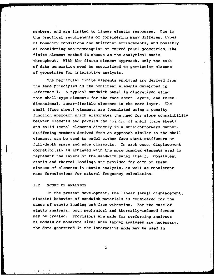
members, and are limited to linear elastic responses. Due to
the practical requirements of considering many different types
of boundary conditions and stiffener arrangements, and possibly
of considering non-rectangular or curved panel geometries, the
finite element method is chosen as the analytical basis
throughout. With the finite element approach, only the task
of data generation need be specialized to particular classes
of geometries for interactive analysis.
The particular finite elements employed are derived from
the same principles as the nonlinear elements developed in
Reference 1. A typical sandwich panel is discretized using
thin shell-type elements for the face sheet layers, and three-
dimensional, shear-flexible elements in the core layer. The
shell (face sheet) elements are formulated using a penalty
function approach which eliminates the need for slope compatibility
between elements and permits the joining of shell (face sheet)
and solid (core) elements directly in a straightforward manner.
Stiffening members derived from an approach similar to the shell
elements can be used to model either face sheet stiffeners or
full-depth spars and edge closeouts. In each case, displacement
compatibility is achieved with the more complex elements used to
represent the layers of the sandwich panel itself. Consistent
static and thermal loadings are provided for each of these
classes of elements in static analysis, as well as consistent
m~ass formulations for natural frequency calculation.
1.2 SCOPE OF ANALYSIS
In the present development, the linear (small displacement,
elastic) behavior of sandwich materials is considered for the
cases of static loading and free vibration. For the case of
static analysis, both mechanical and thermally-induced forces
may be treated. Provisions are made for performing analyses
of models of moderate size; when larger analyses are necessary,
the data generated in the interactive mode may be used in
2
cojnto ihthe larger finite element program described2
Due to limitations in the data generation phase of the
computer program, the class of sandwich panels considered is
flat and rectangular, with arbitrary boundary conditions at
each edge. However, the data generation scheme is organized
so that geometries for non-rectangular or curved panels may begenerated through minor modification of the existing code
(see Section 4). Furthermore, the input information accepted
by the analysis program is in the formats described in
Reference 1, so that data also may be generated manually and
the use of existi~ng interactive plotting software 4is possible.
Each layer of a sandwich panel is modeled explicitly in
the present analysis, so that localized deformations and thermal
stresses due to non-uniform heating can be represented with
high accuracy. The use of a layered model also facilitates
the representation of face sheet and full-depth stiffeners
or panel edge members. These stiffening elements may be located
arbitrarily within the sandwich panel.
3
"mo
SECTION 2
THEORETICAL FORMULATION
The theoretical basis of each class of finite element
(face sheet, core, stiffener) used in the present development
is described in the following paragraphs. Further details of
the element formulations may be found in References 2, 5 and 6.
In each case the starting point is the element potential energy
IT ; for static problems, the true state of equilibrium is
defined simply by the condition
61IT = 0.()
In dynamic (natural frequency) analysis Hamilton's principle
6f2(T - I )dV = 0 (2)tl 1
provides the governing equations, in which T is the kineticenergy.
2.1 THIN SHELL/FACE SHEET ELEMENTS
The development of shell-type finite elements suitable
for the representation of sandwich face sheets is complicated by
the compatibility requirements for elements derived from classical
thin plate or shell theories. The rotational degrees of freedom
dictated by the condition of slope continuity preclude the
direct enforcement of compatibility with standard isoparametric
solid elements. If the layers of the sandwich are to be modeled
explicitly, it is necessary either to derive plate/shell elements
using only displacement degrees of freedom at the bond lines or to
construct higher-order solid elements to represent the core
layers. In the present work, the former approach is adopted.
The thin plate or shell approximation is obtained herein by
4
appropriate specialization of three-dimensional continuum
theory, as aescribed in References 5 and 6.
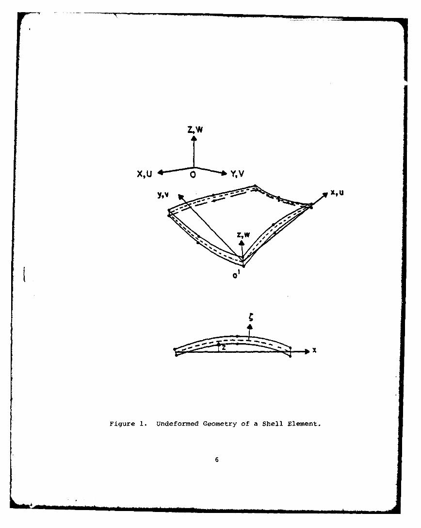
The undeformed geometry of a typical element of a shell is
pictured in Fiqure 1. Local coordinates xy are imbedded in
the base plane of the element, and the height of the middle
surface above the base plane is denoted by Z(x,y). Distances
away from the midsurface are measured by a third independent
coordinate, t. The position of a generic point in the shell
is then
r =xi + yj + zk + Cn (3)
where, if the shell is locally shallow, the unit normal vector
n is
n x= - z,Y + (4)
The assumption of local shallowness also implies that the
coordinate system (x,y,0) is approximately Cartesian.
If the same element of shell material is subject to a
displacement field
= ui + v] + wk, (5)
the displaced position of an arbitrary point is
(x - (Zx + u)i + (y - Zy + v)j
+ (z + C + w)k (6)
By comparing Equations 3 and 6, the three dimensional strains
can be identified, since
2e ijdx dx = aR .aR - ar" ar. (7)
5
-------------------------
X,U 0 Y,V
Figure 1. Undeformed Geometry of a Shell Element.
6
4i
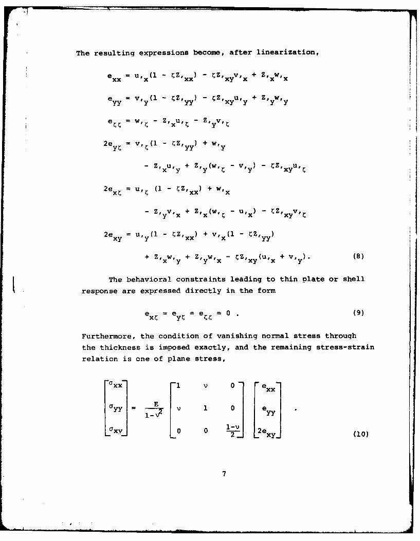
The reutn xrsin become: after line:rization, fxx x xx xy x x
e V, , (1 - CZ, C Z, u, +Z, W,yy yyy xy y y y
W, - Z U,~ - 'VI
2e, =v, C(1 - CZ, )y + w,
- ' Z U, + Z, (w, C V, ) C Z, xyU,C
2ec = , (1 - Cx )+ W
-Z, V, + Z' (w, -U, C Z, vIy x x C x x
2e =U, (1 - CZ, + v, (1 -CZxy y xxyy
+ Z Wy+ Z Wx- CZx (u, x + v1,). (8)
The behavioral constraints leading to thin plate or shellIt response are expressed directly in the form
ec= ey = e, =0. (9)
Furthermore, the condition of vanishing normal stress through
the thickness is imposed exactly, and the remaining stress-strain
relation is one of plane stress,
0xx~ 1 xx
0yy = E v 1 0 e
0XY 0 0 1- 2 exy(0
7
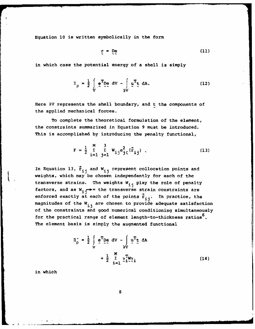
Equation 10 is written symbolically in the form
a = De (11)
in which case the potential energy of a shell is simply
11 = 1 f eTDe dV - J uTt dA. (12)
V 3v
Here W represents the shell boundary, and t the components of
the applied mechanical forces.
To complete the theoretical formulation of the element,
the constraints summarized in Equation 9 must be introduced.
This is accomplished by introducing the penalty functional,
1 M 3 2F Z Z Wij e c (r ) (13)i=l j=l ) ij"
In Equation 13, r.. and W. represent collocation points and
weights, which may be chosen independently for each of the
transverse strains. The weights Wij play the role of penalty
factors, and as W. -o- the transverse strain constraints are
enforced exactly at each of the points r... In practice, the
magnitudes of the Wij are chosen to provide adequate satisfaction
of the constraints and good numerical conditioning simultaneously6for the practical range of element length-to-thickness ratios
The element basis is simply the augmented functional
= D ee dV - u t dA
v aV
M T+ ( Y (14)
i=l
in which
8
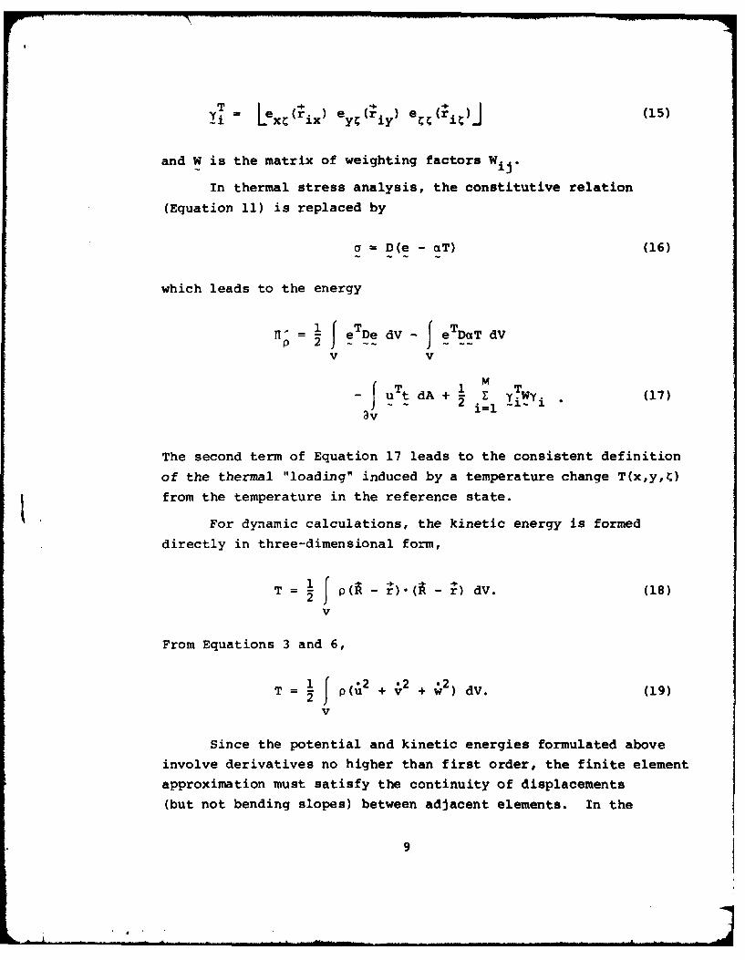
i Lex (ix ey (ri e (r (15)
and W is the matrix of weighting factors Wij.
In thermal stress analysis, the constitutive relation
(Equation 11) is replaced by
a = D(e - aT) (16)
which leads to the energy
= i J eTDe dV - JeTDa T dV
v v
T M TJu tdA + E
- u - + 2 i l Yi Yi (17)3v
The second term of Equation 17 leads to the consistent definition
of the thermal "loading" induced by a temperature change T(x,y,C)
from the temperature in the reference state.
For dynamic calculations, the kinetic energy is formed
directly in three-dimensional form,
T = 1 p(A - r).(R - r) dv. (18)
V
From Equations 3 and 6,
T = 1 p(2 2 + + 2) dV. (19)
v
Since the potential and kinetic energies formulated above
involve derivatives no higher than first order, the finite element
approximation must satisfy the continuity of displacements
(but not bending slopes) between adjacent elements. In the
9
present study, the simplest permissible form of approximation,
based upon linear polynomial shape functions, is used. The
resulting element is shown in Figure 2. Despite the simplicity
of the approximation, the element exhibits high accuracy in both
displacement and stress computations, and is particularly
straightforward to use in comparison with many other shell
finite elements. Linear and nonlinear analyses which demonstrate
the accuracy and economy of the present shell element formulation
can be found in Reference 6.
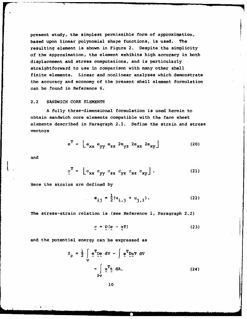
2.2 SANDWICH CORE ELEMENTS
A fully three-dimensional formulation is used herein to
obtain sandwich core elements compatible with the face sheet
elements described in Paragraph 2.1. Define the strain and stress
vectors
eT = Lexx e yy ezz 2e yz 2e J (20)
and
LT Lxx yy zz , x (21)
Here the strains are defined by
1eij = 2(ui j + uj,i). (22)
The stress-strain relation is (see Reference 1, Paragraph 2.2)
a= D(e - aT) (23)
and the potential energy can be expressed as
I1p= 1 f eTDe dV e TDaT dV
v
0 Tt dA. (24)av
10
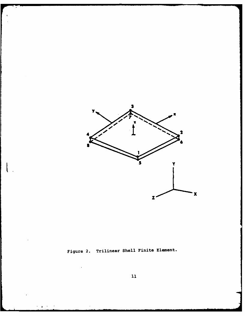
X x
Figure 2. Trilinear Shell Finite Element.
Similarly, the kinetic energy is
T. 0(l 2 + 2'pu v w)dV. (25)
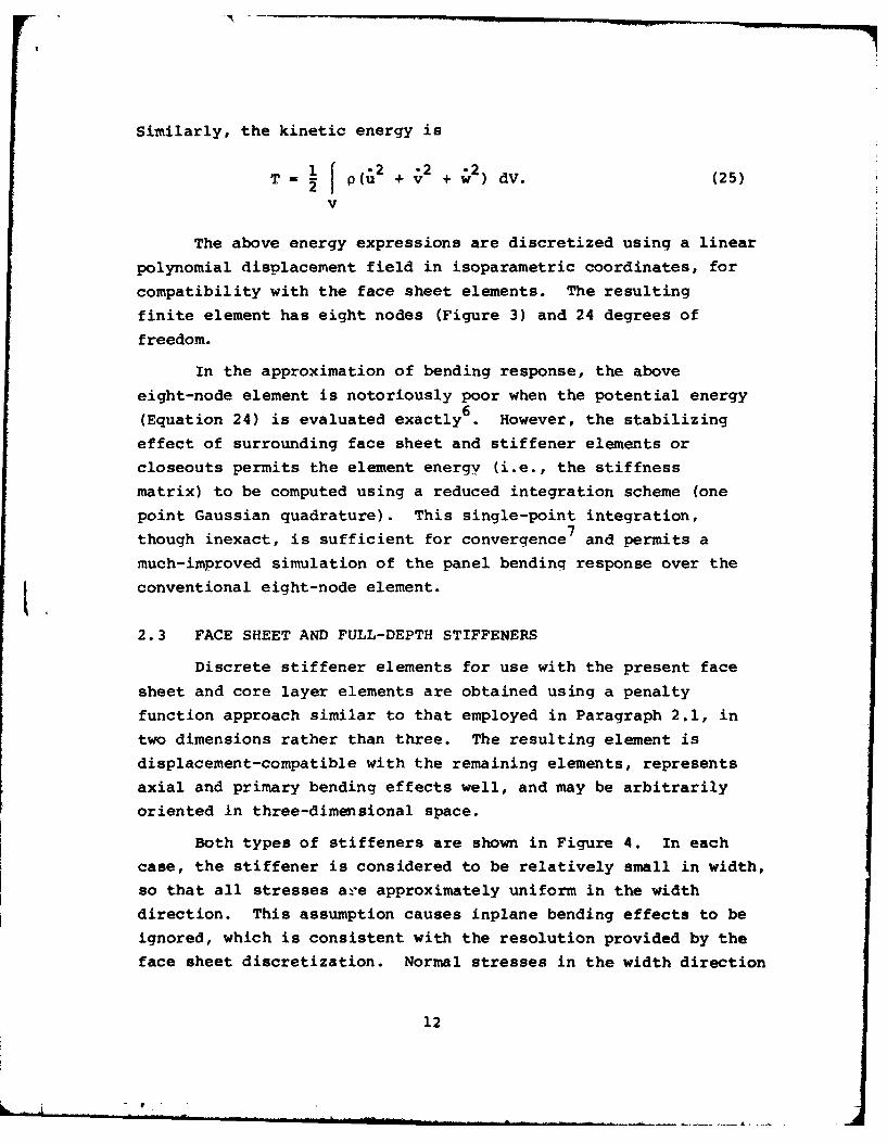
The above energy expressions are discretized using a linear
polynomial displacement field in isoparametric coordinates, for
compatibility with the face sheet elements. The resulting
finite element has eight nodes (Figure 3) and 24 degrees of
freedom.
In the approximation of bending response, the above
eight-node element is notoriously poor when the potential energy6(Equation 24) is evaluated exactly .However, the stabilizing
effect of surrounding face sheet and stiffener elements or
closeouts permits the element energy (i.e., the stiffness
matrix) to be computed using a reduced integration scheme (one
point Gaussian quadrature). This single-point integration,
though inexact, is sufficient for convergence 7and permits a
much-improved simulation of the panel bending response over the
conventional eight-node element.
2.3 FACE SHEET AND FULL-DEPTH STIFFENERS
Discrete stiffener elements for use with the present face
sheet and core layer elements are obtained using a penalty
function approach similar to that employed in Paragraph 2.1, in
two dimensions rather than three. The resulting element is
displacement-compatible with the remaining elements, represents
axial and primary bending effects well, and may be arbitrarily
oriented in three-dimensional space.
Both types of stiffeners are shown in Figure 4. In each
case, the stiffener is considered to be relatively small in width,
so that all stresses are approximately uniform in the width
direction. This assumption causes inplane bending effects to be
ignored, which is consistent with the resolution provided by the
face sheet discretization. Normal stresses in the width direction
12
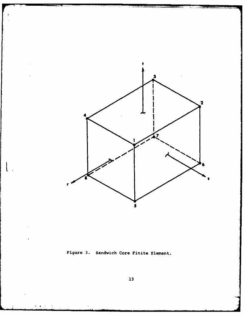
Figure 3. Sandwich Core Finite Element.
13
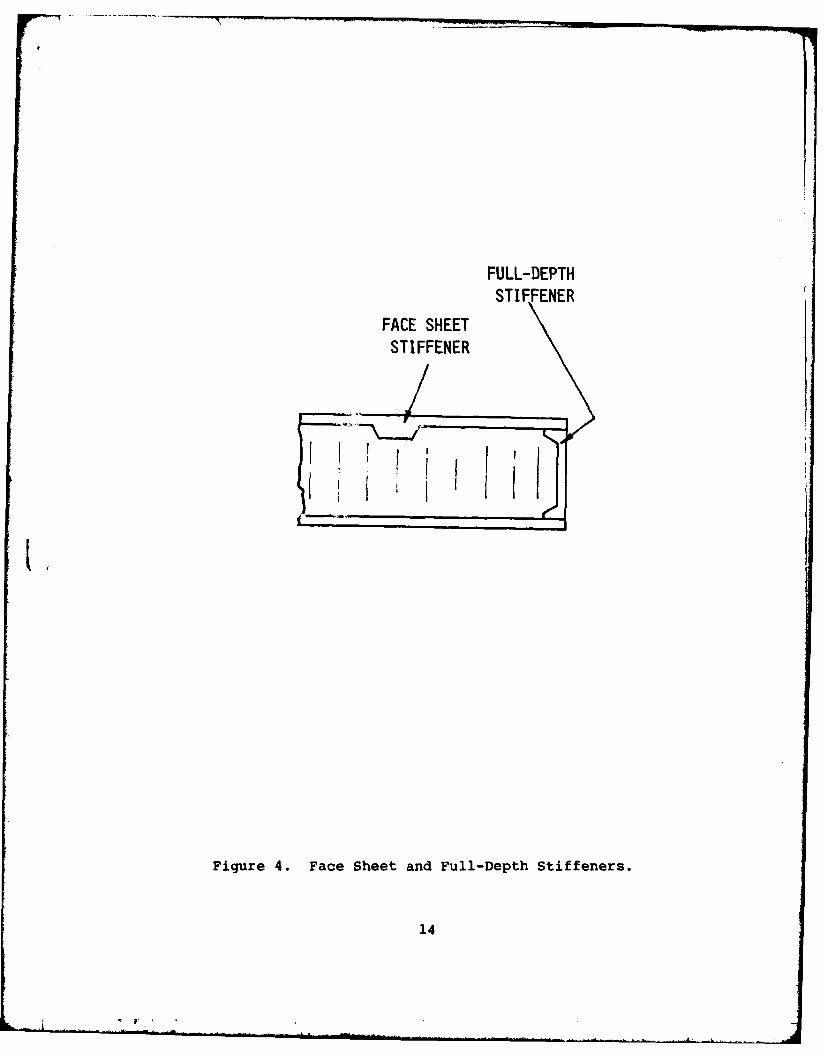
FULL-DEPTHST IFFENER
FACE SHEETSTI FFENER
Figure 4. Face Sheet and Full-Depth Stiffeners.
14
are also neglected; thus, the stiffener is subject to a plane
state of stress in the remaining dimensions, although arbitrary
warping and twisting of the element is permitted.
The strain energy of a typical element involves only the
longitudinal strains, which give rise to both axial and bending
forces in the deformed state. Remaining components of strain
(transverse shear and normal strain in the depth direction) are
suppressed through the use of penalty function constraints
(see Paragraph 2.1). Denoting the longitudinal direction by x,
the potential energy is simply6
11 ~ x -e 2f EaTe xdVv v
- J tdA (26)
av
where E is the elastic modulus, and the kinetic energy is
T (2 + w )dV. (27)L vTo enforce the remaining constraints
e = e = 0, (28)
introduce the penalty functional
1 2 4-x) + 1 2F = 2 W x e XZ~r x 2 zezz(r Z ) (29)
in which Wx, Wz are the constraint weights and rx, rz are the
corresponding collocation points. Analogous to the procedure
of Paragraph 2.1, the functional F is added to the potential
energy (Equation 26) to form the constrained energy on which
the element stiffenss matrix is based:
15
P~~ 2 EexdV -JEcTexdV
v v
1 2 2
- J tdV. (30)av
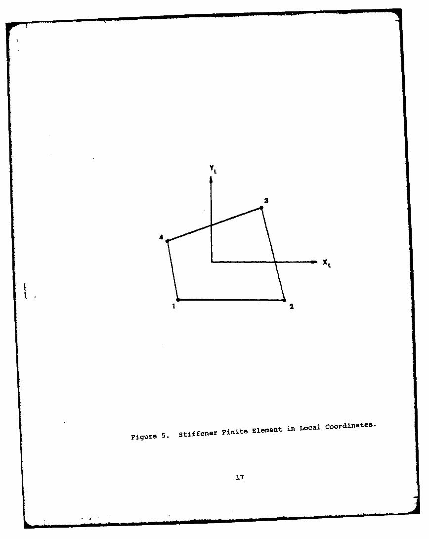
The above potential and kinetic energies are last in
discrete form through a linear approximation of the displacements
u within individual elements. The resulting finite elements,
shown in Figure 5, have four nodes and twelve degrees of freedom.
For this order of discretization, the element strain energy may
be evaluated exactly using a four-point (2 by 2 Gauss) integration
rule. The transverse strain constraints (Equation 28) are each
applied at a single point corresponding to the element centroid
location.
16
LX
Figure 5. StiffeerFnt em t in Local Coordinates.
17
SECTION 3
NUMERICAL SOLUTION TECHNIQUES
The methods used in solving the governing matrix equations
for a complete finite element model are described in this Section.
Two general types of solutions are presented: linear simultaneous
equations, for static analysis with mechanical and/or thermal
loading; and generalized eiqenvalue systems, for use in natural
vibration analysis.
3.1 LINEAR STATIC ANALYSIS
In static analysis, minimization of the discrete potential
energy for an assemblage of elements leads to the matrix
equation
KU = T (31)
in which K is the stiffness matrix, U are the (unknown) nodal
displacements, and T is the load vector including both mechanical
and thermal generalized forces. A direct solution is obtained by
a Gauss-Doolittle factorization of K, followed by forward and
backward substitution. The decomposition of K is of the form
TK = LDLT. (32)
Here L is a unit lower triangular matrix,
{(nonzero) , i>j
ij =1, i=j
0, i<j (33)
and D is a strictly diagonal matrix. Next let
Z = DLT U (34)
18
and the relation
LZ = T (35)
can be solved for Z by a forward substitution. From Equation 34,
LTU = D-1 z (36)
which can then be solved for U in a backward substitution step.
Having solved for the nodal displacements U over the entire
finite element model, a complete vector of displacements can be
extracted for each individual element. The element displacement
vector, along with the shape functions for an element, completely
describe the state of displacement (and, therefore, strain and
stress) within each element of the model.
3.2 NATURAL FREQUENCY SOLUTION
In natural vibration analysis, the discretization of both
the potential and kinetic energies and the assumption of
harmonic motions vield the governinq system of equations
KU =w 2MU (37)
Here K and M are the stiffness and mass matrices, respectively, U
is the nodal displacement vector, and w is the circular frequency
of vibration.
It should be noted in Equation 37 that the mode shape U
describes only the relative displacements of the mesh points
(aU, where a is a constant, is a solution as well). If matrices
K and M are of order N, then there exist N-solutions of Equation
37: w i; i=1,2 ...... ,N. Usually only the lowest several
frequencies and mode shapes are of interest, and thus a vector
iteration procedure is most appropriate for solvinq the system.
An approach based upon simultaneous vector iteration 8 is used herein.
19
Factoring the stiffness matrix by Choleski's method gives
K = LLT. (38)
Equation 37 can now be restated as the standard eigenvalue problem
AV = XV (39)
in which
A = L- ML- T (40)
V =LTU (41)
and
1 (42)
The eigenvalue solution is performed using a set of m trial
vectors, where m is greater than the number of frequencies
desired but is generally much less than N. These trial vectors,
which are arranged in the partial modal matrix
=D .= ( (43)
gradually converge to the first in eigenvectors (mode shapes)
as the iteration proceeds.
The central step in the simultaneous iteration is the
function of the m by m interaction matrix
B = 4TAD. (44)
When the iteration has converged, B is a diagonal matrix since
all of the vectors Vi are orthogonal with respect to A. Before
20

the solution has converged, an approximate eigenvalue analysis
of B is performed at each iteration to generate improvedestimates of the eigenvlaues and to modify the iteration matrix 0.Details of the implementation of this procedure may be found in
Reference 8.
21
SECTION 4
COMPUTER PROGRAM DESCRIPTION
The finite element discretization and numerical solution
procedures summarized in Sections 2 and 3 are implemented in a
computer program which permits the interactive solution of static
and natural frequency problems for sandwich composites. Auxiliary
programs are used in conjunction with the primary analysis
program to perform the tasks of data input and generation, and
of presentation of results.
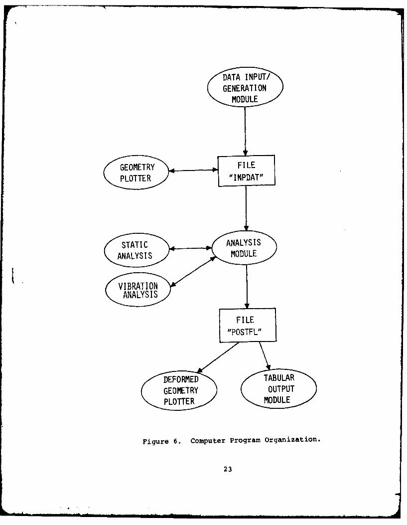
4.1 PROGRAM FUNCTIONS AND ORGANIZATION
The system of computer programs which are used for the
interactive analysis of sandwich panels are pictured in Figure 6.
A data generation program is used to prepare data interactively
for use in the main analysis program. The sandwich analysis
input data (file INPDAT) conforms to the input data formats of
Reference 1, which in turn are patterned after those of the
MAGNA general purpose finite element program 4. Thus, the geometryplotting capabilities described in Reference 9 may be used to
obtain line drawings of the generated mesh for documentation
purposes when required. Once the requested analysis has been
performed, a summary of results is stored on disc (file POSTFL)
for deformed geometry plotting9, listing by separate outputformatting program, or listing on the line printer.
4.2 INTERACTIVE OPERATION
The interactive programs described here are of three types:
data input and generation; static or natural frequency analysis;
and tabular output. Operating instructions for compatible pre-
and post-processing graphics programs are given in Reference 9.
Data generation is performed using a minimal amount of
input from the user concerning the panel geometry, properties,
supports, loading, temperature distribution and mesh divisions.
In particular, the following data are requested:
22
DATA INPUT/GENERATI ON
MODULE
L:EtER PEFIL
FiguTRe 6.CopuerPogam ranzt
STATIC NALYS3
1. ANALYSIS TYPE: static or natural frequency solution.
2. NUMBER OF MODES: number of natural frequencies andmode shapes to be solved in vibration analysis.
3. TYPE OF LOADING: mechanical or thermal loads (orboth) in static analysis.
4. PANEL DIMENSIONS A,B: planform dimensions of thesandwich panel in the x,y directions. At present,the data generation program is restricted to flat,rectangular panels.
5. LAYER THICKNESS TL,TC,TU: thicknesses of lower facesheet, core layer, and upper face sheet.
6. FACE SHEET PROPERTIES E,NU,ALFA,RHO: Young's modulus,Poisson's ratio, coefficient of thermal expansion anddensity (requested for each face sheet in turn).
7. CORE PROPERTIES GX,GY,ALFAX,ALFAY,RHO: shear moduli,coefficients of thermal expansion and density forthe core layer.
8. NUMBER OF STIFFENERS NSX,NSY: number of stiffeningmembers in the x and y directions, respectively. Bothface sheet and full depth stiffeners are included.
9. STIFFENER LOCATIONS X(OR Y), ITYPE: for each stiffeningmember, the constant value of x or y at which themember is located is requested' valid x-values are between0 and A, and valid y-values are between 0 and B. Foreach member, the type is also requested (lower face,upper face, full depth).
10. STIFFENER PROPERTIES E, ALFA, T, RHO: for eachstiffener, these are the values of the Young's modulus,the coefficient of thermal expansion, the stiffenerwidth, and the mass density.
11. SUPPORT CONDITIONS ISO,ISA,JSO,JSB: for each of theedges of the panel (x = o,a; y = o,b), a boundarycondition must be specified. Support conditions whichcan be chosen independently at each panel edge include:free, simple support, clamped, symmetric andantisymmetric.
12. PRESSURE LOADINGS PLPU: in linear static analysis,pressures may be specified on the lower or upper facesheet surfaces, or both. Note that all pressure valuesare positive upward.
24
13. POINT LOADINGS XP,YP,FORCE: location and magnitudeof point loadings for static analysis.
14. NUMBER OF ELEMENTS PER EDGE NEX,NEY: this datadefines the degree of mesh refinement in the modelby dividing the sandwich panel into a rectangulargrid of NEX by NEY finite elements. Usually amoderate number of elements (4-6 per edge) providesa good balance of accuracy and solution cost.
15. GRID POINT LOCATIONS XG (OR YG): along each side ofthe panel, the locations of grid lines may be specifiedto generate nonuniform (graded) meshes. NEX41 locationsmust be specified along the x-axis, and NEY+1 locationson the y-axis. Note that each of the stiffenerlocations specified in Item 9 must correspond to a gridline location.
In addition to geometric parameters and other data defined
in the interactive mode, tenperature data must be supplied if
thermal stress analysis is to be performed. By default, the
data generator will create temperature data for a uniformly
heated panel (T = 1000, in consistent units). To specify a
different temperature distribution, the user must supply a
separate subroutine to generate the required data T = T(x,y,z).
This user-written subroutine has the form shown in the following
example, for which the temperature distribution is
T(x,y,z) = 1.2Ze - 0 2 8 x (45)
The appropriate user subroutine (which always has the name
UTEMPS) is
SUBROUTINE UTEMPS (X,Y,Z,T)T = 1.2*Z*EXP(-0.028*X)RETURNEND
User subroutine UTEMPS is called once for every generated point
in the finite element model.
The analysis is next performed by simply loading and
executing the analysis module. While the final results of an
analysis are written to the file POSTFL for later processing,
25
certain information, including diagnostic arnd warning messages,
is output directly at the user's terminal. In the event that a
problem becomes too large for the interactive program, the
analysis can be performed in the batch mode using the program
of Reference 1, since the input data are fully compatible.
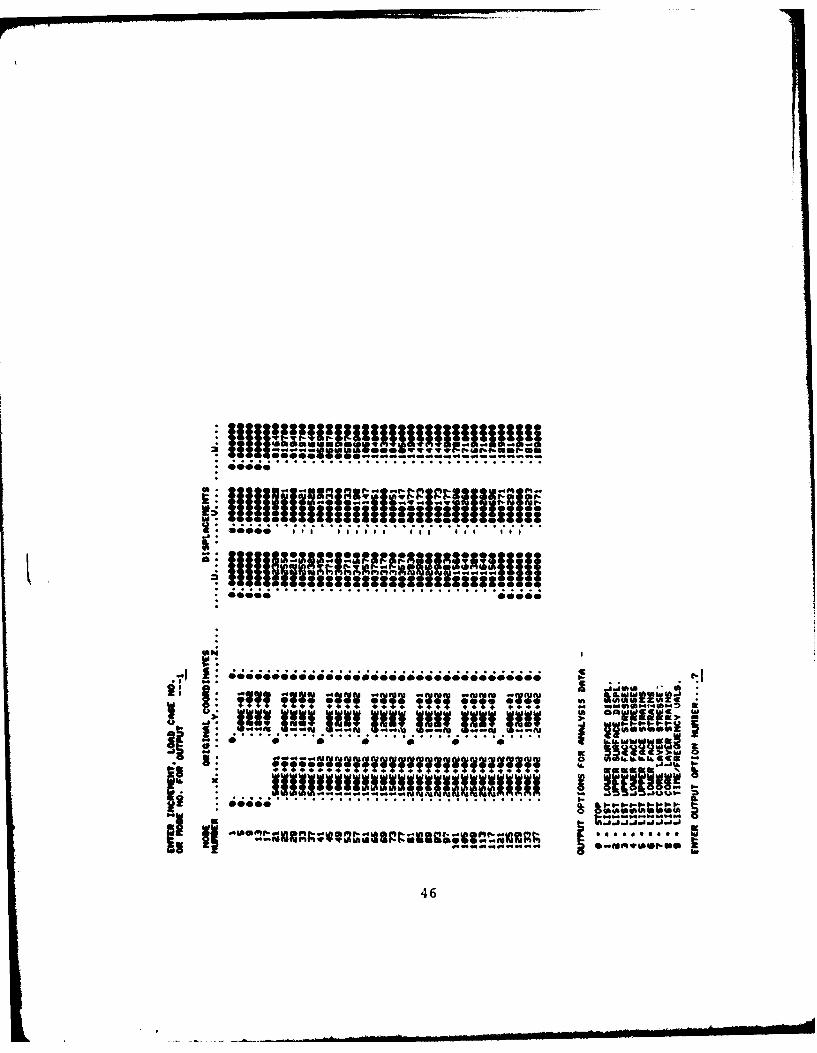
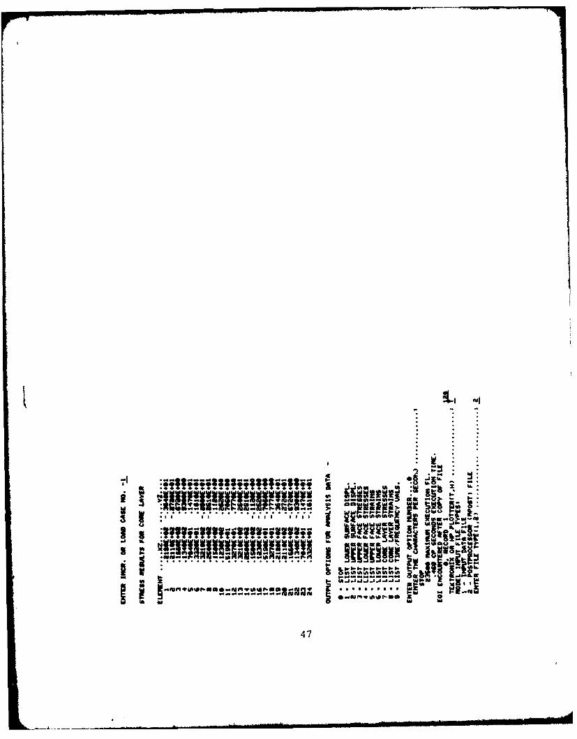
Following the analysis step, tabular results may be
printed by simply executing the output module. Analysis results
provided in table form include deflection data on selected grid
lines, and strain and stress data at individual element centroids.
Alternatively, the file POSTFL may be used as input to graphics
programs 9 which produce deformed geometry plots for each
visualization of the problem results.
26
'I.'____----- ________....______-_______________________
SECTION 5
SAMPLE ANALYSES
Typical analyses performed using the solution techniques
described in Sections 2 and 3 are presented in this section.
Static problems involving mechanical and thermal loading, as
well as natural frequency solutions, are discussed. The operation
of the analysis program is demonstrated in greater detail in the
sample terminal session included in the Appendix.
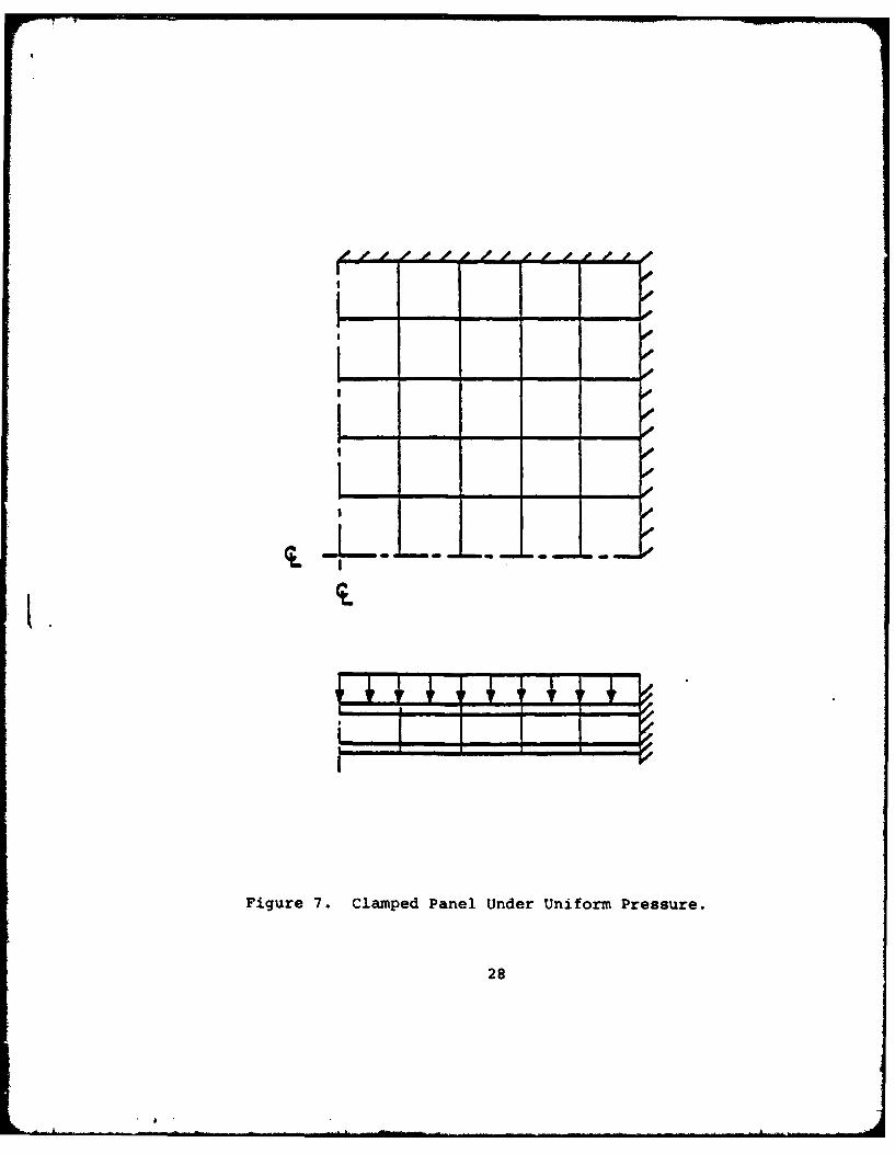
5.1 STATIC ANALYSIS WITH MECHANICAL AND THERMAL LOADS
To demonstrate the static analysis option, a rectangular
panel previously studied by Monforton1 0 and Kan and Huang I I is
considered. The flat sandwich plate has the following geometry
and properties:
Planform: a=b = 50 inches
Thicknesses: tf= 0.015 inches
tc = 1.000 inches
Face Material: E = 10.5 x 10⁶ lb/in2f
V f = 0.30
CL = 12.4 x 10- 6 in/in*F
Core Material: Gc = 50000. lb/in 2
a= 12.4 x 10- 6 in/inF
Using these parameters, a static solution is performed for
the case of a fully clamped boundary and uniform lateral pressure
(Figure 7). Due to symmetry of the problem only one quarter
of the panel is modeled. The mesh consists of a 5 by 5 grid
of elements in each layer, for a total of 260 unconstrained
degrees of freedom. For a unit lateral pressure, the computed
central displacement is w = 0.113 inches. This value is in good
agreement with previously published results; for example,
linearization of the results of Reference 11 gives wc = 0.09497
inches.
27
. L
!a -
I
I
I .
I II
Figure 7. Clamped Panel Under Uniform Pressure.
28
" -' - -. .. .... .. ... I ... .|lii.. . .. lia...... ... II ....... . ...... . ..... A'-m| - I .e
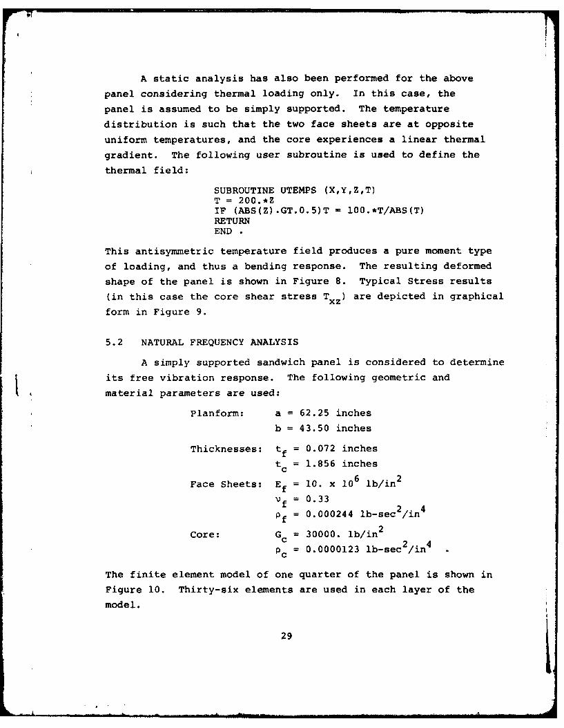
A static analysis has also been performed for the above
panel considering thermal loading only. In this case, the
panel is assumed to be simply supported. The temperature
distribution is such that the two face sheets are at opposite
uniform temperatures, and the core experiences a linear thermal
gradient. The following user subroutine is used to define the
thermal field:
SUBROUTINE UTEMPS (X,Y,Z,T)T = 200.*ZIF (ABS(Z).GT.O.5)T = 100.*T/ABS(T)RETURNEND
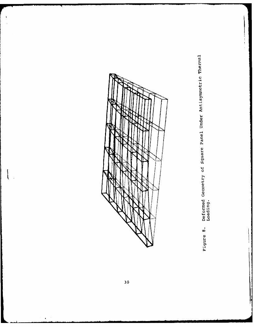
This antisymmetric temperature field produces a pure moment type
of loading, and thus a bending response. The resulting deformed
shape of the panel is shown in Figure 8. Typical Stress results
(in this case the core shear stress Txz) are depicted in graphical
form in Figure 9.
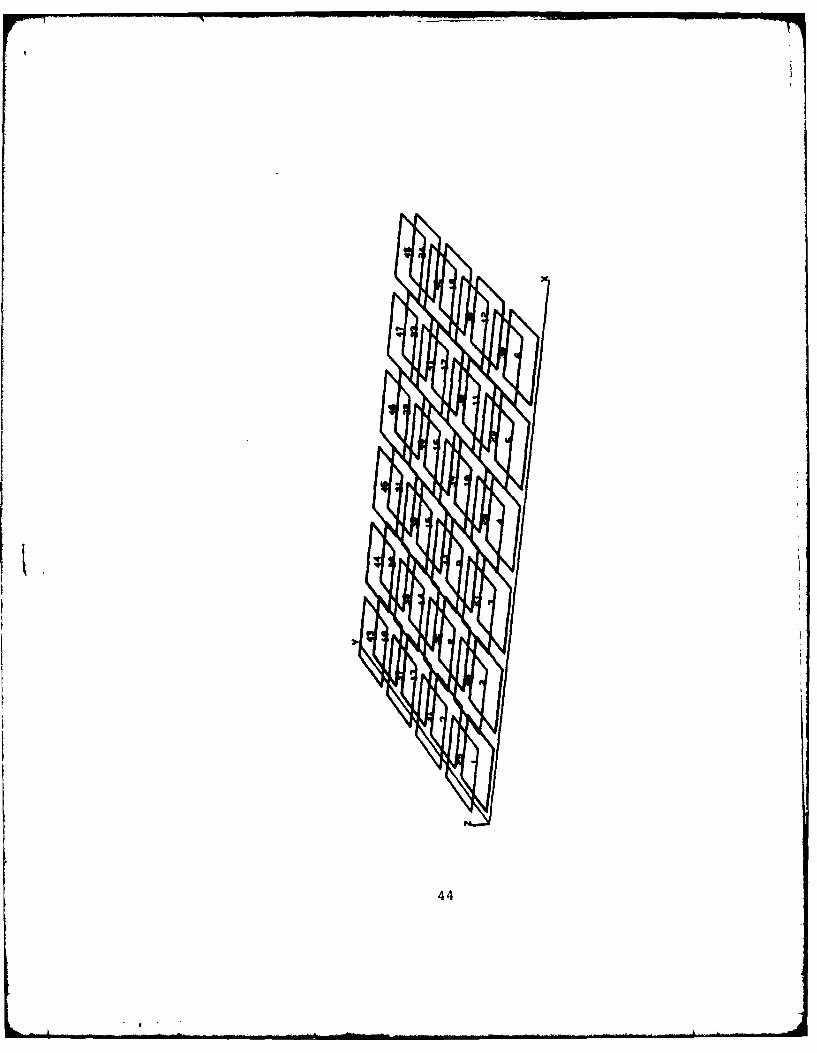
5.2 NATURAL FREQUENCY ANALYSIS
A simply supported sandwich panel is considered to determine
its free vibration response. The following geometric and
material parameters are used:
Planform: a = 62.25 inches
b = 43.50 inches
Thicknesses: tf = 0.072 inches
t = 1.856 inchesc
Face Sheets: Ef = 10. x 106 lb/in2
V f = 0.33
Pf = 0.000244 lb-sec2/in4
Core: Gc = 30000. lb/in 2
PC = 0.0000123 lb-sec /in
The finite element model of one quarter of the panel is shown in
Figure 10. Thirty-six elements are used in each layer of the
model.
29
a
-4
'-4
0
144s(0
Q) 0
'44
300
-- -~ -----
..... ......... ... .................. ..... .......... ... ... ". ......... "...... .... r-:... .. .I .I I.I. .....
r i i 6 f "- 'u
S ....... ..... . _ .... . ,...!.... ....... ... ......... .. 0,.. -1
• 1 ' I * "... . .
. . 4 ...
Si I :/ .. ,,.
~~~. ........... t\ T /i1"
.1 ............ ............ .... 0. . \ ........
313
.. ...... ........... ....... ............ ........ .......... ... ............ .lJ
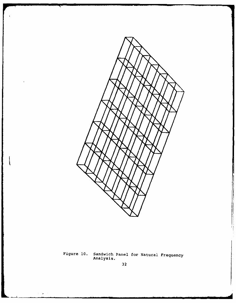
Figure 10. Sandwich Panel for Natural FrequencyAnalysis.
32
The solution for the fundamental frequency of the panel
using th.e model shown yields 1 = 174 Hz. This value compares
well with the classical analytical solution1 2 of i = 170 Hz.
A second solution has also been performed for a similar
panel of larger aspect ratio. Panel data for this example
is identical to the problem above, with the following exceptions:
b = 34.00 inches
tf = 0.063 inches
t = 1.874 inches.
In this case, the computed. frequency of 240 Hz is also in good
agreement with a closed-form solution 12 of wi = 250 Hz.
It
33
SECTION 6
SUMMARY AND CONCLUSIONS
A finite element approach for the static stress analysis
of sandwich panels under mechanical and thermal loadings,
and for the natural frequency analysis of sandwich, has been
described. Layers of a sandwich panel are modeled explicitly,
so that unequal face sheets, stiffening members, and other
design details are represented with relatively high accuracy.
Due to the finite element basis of the present methodology,
rather arbitrary geometries and variations in mechanical pro-
perties are easily considered.
The methods described are suitable for interactive use,
to facilitate parametric and design studies. Data generation
utilities, which permit the definition of simple panel geometries
from a minimal amount of input, are provided to support this
mode of usage. Generated input is compatible with that of a
comparison program with larger capability. Results are out-
put in a form suitable for plotting using existing computer9
graphics programs.
The developments described herein can be improved to
provide more detailed and comprehensive analytical capabilities
(e.g., curved panels, arbitrary stiffener shapes, linear
buckling analysis, etc.). However, in their present form,
the methods presented represent a valuable capability for
practical design analysis of sandwich composite structures.
34
APPENDIX
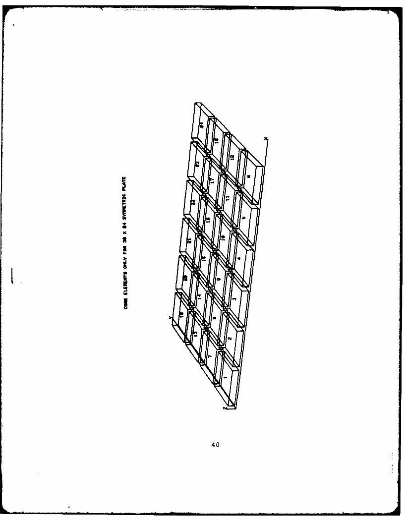
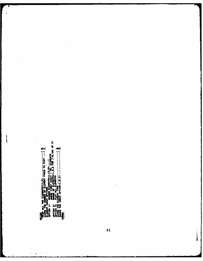
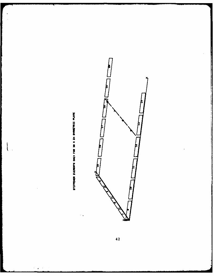
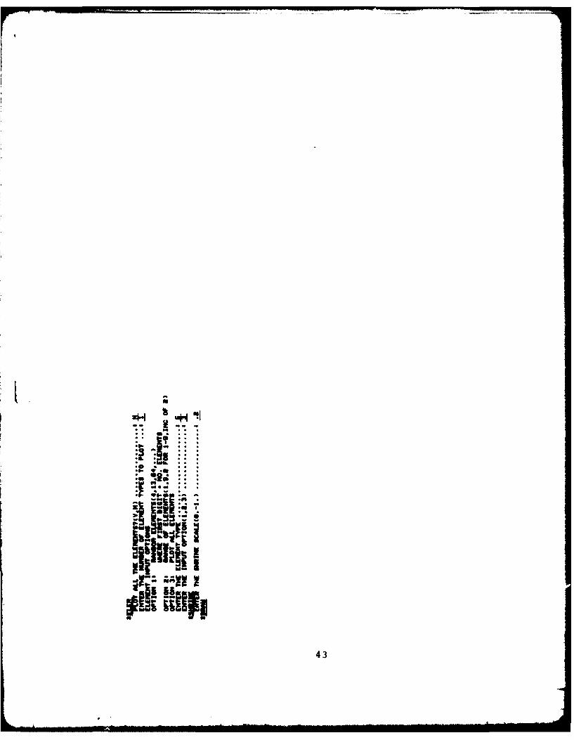
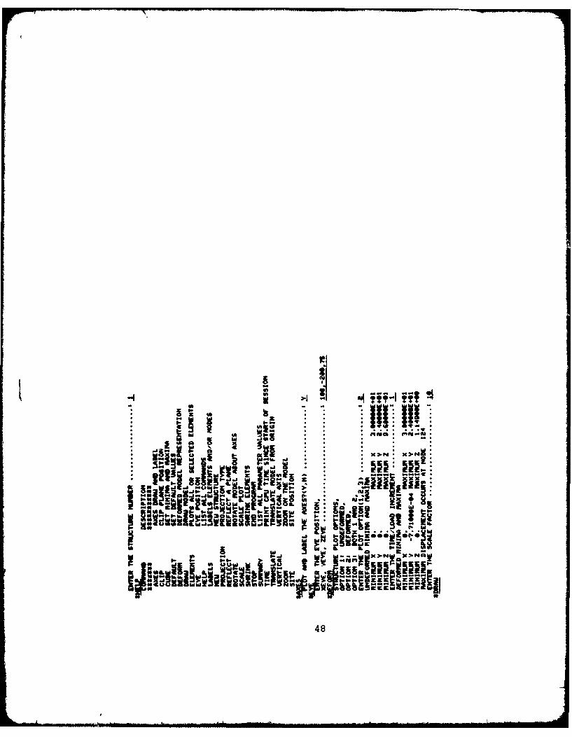
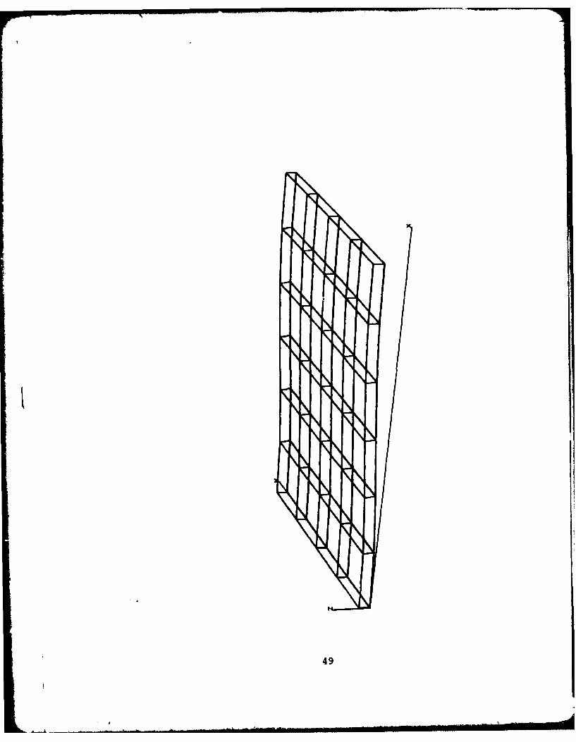
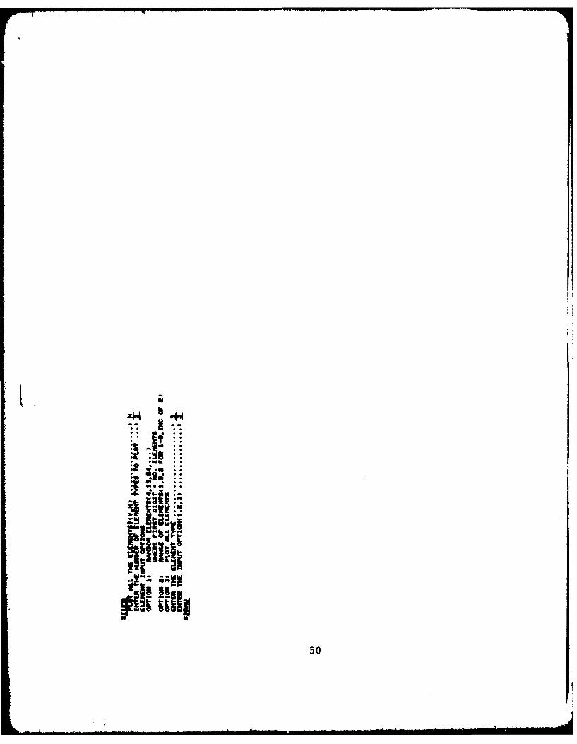
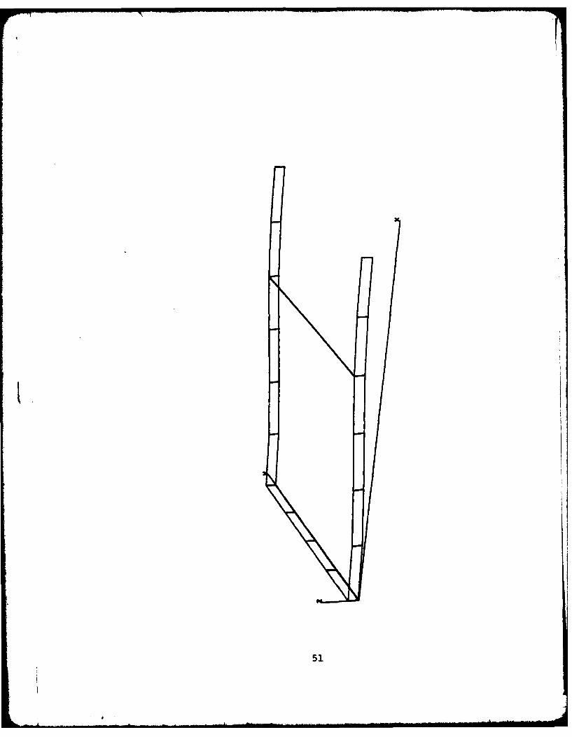
SAMPLE INTERACTIVE TERMINAL SESSION
A typical interactive analysis session using the sandwich
analysis program described herein is reproduced in this Appendix.
This sample session demonstrates the procedures for accessing
and executing the data generation, analysis and plotting
programs, and illustrates the types of output which can be
obtained from the analysis.
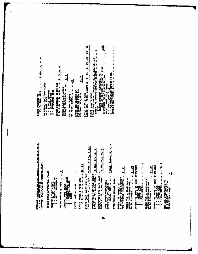
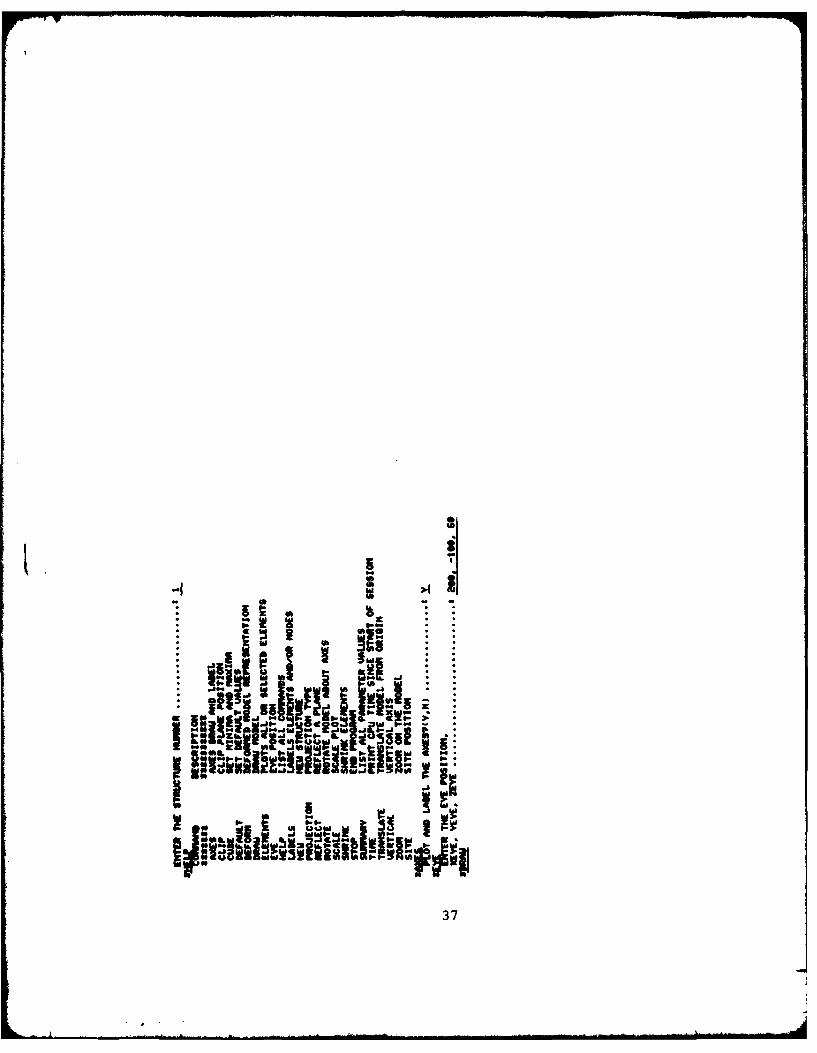
The analysis procedure is initiated by accessing a stored
control language procedure file (denoted by "PROCFIL" in the
example), and issuing a command to start the procedure:
BEGIN,SWICH,PROFIL.
This command automatically invokes the data generation, analysis
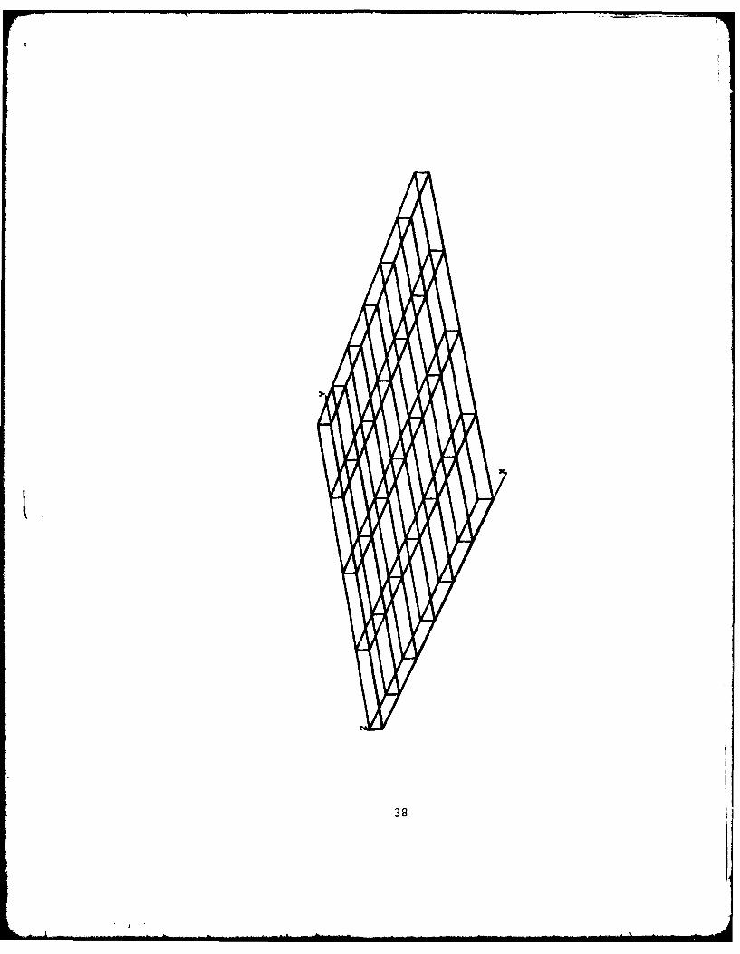
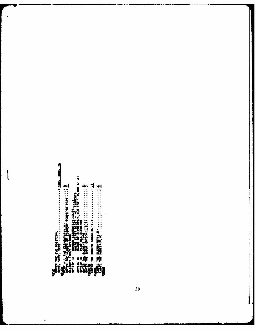
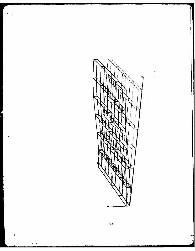
and tabular output modules. By appending the keyword "PLOT"
to the BEGIN command, a geometry plotting utility is also
executed before and after the analysis module. The "PLOT"
option is used in the sample session to clarify the problem
geometry and results.
35
-~~~~~~~~ o-- _ _ _ __ _ _ _ _ _ _
117.0 M.- zaff
Iwo~~- J. 'm.AWor ?.3 1
!jU
i..
I: P
w . I., . -I; at ! W
W116 z. gz, v~ L i Sal S. leti I i!, --... f5
Sa "L I --
af a.j 4A .
Ow IF* IOASg-
36. .Im
I.
-I . . I s :
--- I .I i - * -..I2,tlF ..ti i. ! .
i f , -oIi I .. I I w-
I37
37
38
r 7t
44W
-.
i t• it' ll- awl
~PON
39
2U
IUx
II
40
rI illI.5 0
Ih
41
88Th\
Ujfl\\1. *8II
42
H
*!1 !i I,::sti I
All44
.. I-:.
1til51ili .
43
44
4* * I '' ill, I
* * *
- Jl ... ..... . .. .~~ .. .. . ... . . . ... .. .S1 [I.. . ..... . ..
I - , ..... . -.. - -
- *4 t CUP.m,
l ..... ... . .. ..... .....t"off
OO Is: -gsO- a OO zp
... ... !: . . . .1 " : I e........:" . .na .. an "0 0 0 0
iizz.;! 1 .. .. ..........-m IIittttsan ga iiiliit cag
46
J611
i :,',.....,........:''' < , fi ' ! l . - !
tI IN
47
iiz P;Cw 9 ~~X 1H *.
U PW
H"0,9 Iu IN 51 wf-u~~~9. .mm..ssa~a -
0 -
48
49
IL U
ZN4'4
.~ -i: ~: :~ ::
.0- v.a:. *L.
.4.,~ a.
4'iiPj~ 04
~iii liII;
50
51
Oil ii II flltt!* . **. . . ...
i!! "-...i 4i il 1444:* - f i!. .* .1i .
52
*1**..
'I.
* . . .* * ,
* * * *1~
: *~*.
* i f~X' ~ * : :* * * S.
*5 * **. ~: *. * ::
~' ~*i* *;i.: *~:,i :* 5'**. 3
Sr. * I* : :.* L
~: ~I
S 5 555
'S* *511
i-i S'S.
55 ** 55* *1
* *
.5...
* S *
5. 555* *15*
S 5 5 *5* 5S
S. S5'
* .: : * *I *.*'.;* S 5 55* S S S~.
S S * * 5
o * . S
* S S
''S
53
h
lf
K. ....
hu I
INS
54
REFERENCES
1. R. A. Brockman, "Nonlinear Finite Element Analysis ofSandwich Composites," AFWAL-TR-81-3008, Wright-PattersonAir Force Base, Dayton, Ohio, April 1981.
2. F. K. Bogner and M. L. Soni, "Minimum Weight Design ofFlat Sandwich Panels Under Edgewise Compression Loads,"AFWAL-TR-81-3009, Wright-Patterson Air Force Base, Dayton,Ohio, April 1981.
3. R. A. Brockman, "Stability of Flat, Simply Supported,Rectangular Sandwich Panels Subjected to Combined InplaneLoadings," AFFDL-TR-76-14, Wright-Patterson Air ForceBase, Dayton, Ohio, September 1976.
4. R. A. Brockman, "MAGNA Computer Program User's Manual,"UDR-TR-80-107, University of Dayton Research Institute,Dayton, Ohio, November 1980.
5. R. A. Brockman and F. K. Bogner, "An Efficient Three-Dimensional Shell Finite Element for Highly NonlinearProblems," in Advances in Computer Technology - 1980,Volume 2, A. Seireg, editor, A.S.M.E., 1980, pp. 219-226.
6. R. A. Brockman, "A Penalty Function Approach for theNonlinear Finite Element Analysis of Thin Shells," Ph.D.Dissertation, Department of Mechanical Engineering,University of Dayton, Dayton, Ohio, July 1979.
7. 0. C. Zienkiewicz, The Finite Element Method, McGraw-HillCompany, London, 1977.
8. R. B. Coor and A. Jennings, "A Simultaneous IterationAlgorithm for Symmetric Eiqenvalue Problems," InternationalJournal for Numerical Methods on Engineering, Vol. 10,pp. 647-663, 1976.
9. R. A. Brockman, M. E. Wright, M. P. Bouchard, and M. J.Hecht, "Structural Analysis Postprocessing Utilities,"AFWAL-TR-80-3151, Wright-Patterson Air Force Base, Dayton,Ohio, November 1980.
10. G. R. Monforton, "Discrete Element, Finite DisplacementAnalysis of Anisotropic Sandwich Shells," Report No. 39,Division of Solid Mechanics, Structures and MechanicalDesign, Case Western Reserve University, 1970.
55
11. H. P. Kan and J. C. Huang, "Large Deflections ofRectangular Sandwich Plates," AIAA Journal, Vol. 5,pp. 1706-1708, 1967.
12. F. J. Plantema, Sandwich Construction, John Wiley and Sons,New York, 1966.
56
56


![[Shinobi] Claymore 095](https://img.pdfslide.us/doc/110x75/568bd68f1a28ab20349c8aa9/shinobi-claymore-095.jpg)