Embed Size (px)
Citation preview

AD-A117 160 ARMY MISSILE COMMAND REDSTONE ARSENAL AL RESEARCH D--ETC F/S 17/sAPHOTONIC SEEKER DEVELOPMENT.(U)JUN 82 J DUTHIE. P R ASHLEY. J UPATNIEKS
UNCLASSIFIED NL,/EEEEIEEEEHi/
nosnsoo 7•

DU'HII, ASHLEY, UPATNIEKS & LIU 18 JUN196S
PHOTONIC SEEKER DEVELOPMENT (U)
*JOSEPH C. DUTHIE, DR., PAUL R. ASHLEY, DR.
RESEARCI DIRECTORATE, US ARMY MISS]LE LABORATORYUS ARMY MISSILE COMMAND
REDSTONE ARSENAL, ALABAMA 35898AND
JURIS UPATNIEKS, MR.** AND 1H. K. LIU, DR.***
INTRODUCTION
Ideally, a seeker system to be used for target identification and nis-
sile guidance should be able to recognize the target over an extendud setof ranges, orientations and aspects. In the most simple scenario a singlefeature such as a characteristic infrared emission or designation of the
target by an aimed laser spot will suffice. However, for autonomous seekerswhich have to seek out and destroy energy targets without the aid of laserdesignators or where the differentiation between friend or foe is moredifficult, far more information has to be processed than may be possible by
electronic means.
Consider the problem of identifying and correctly locating a singlescale, orientation and aspect of an. enemy vehicle in a snapshot taken with
a typical instamatic camera. For this example we will take the focallength of the lens to be 2 cm, the lens aperture to be I cm, the wavelength
of the light to be 5 x 10 - 5 cm and the field of view 1 cm x 1 cm. Thenumbers are useful only for order of magnitude calculation and need not re-present an actual system. In the image plane the size of the resolutionelements is lo- 4 cm. Thus, the image may be thought of as a 104 x 104 array
ci of resolvable elements. To recognize and locate the tank, the optimumestimator can be shown to be the cross correlation between a known image ofthe tank and the image to be searched. For an image consisting of 104 x1O0
LLi resolvable points, this involves computing two separate 104 x I04 pointFourier Transforms, multiplying the two together then forming 1he 104 x 104
L. point Fourier Transform of the resultant. A total of about 10 multipli-cations is involved. The task of doing this at T.V. frame rates requires
_ * Permanent Address: fncirgnmeg R ~sea~cb InshftUhl,8 Michigan•.ox oo nn r or, m• Permanent Address: University of Alabama, Tuscaloosa, AL 35486
DTIC DIUTION STATEMENT AE L ECTE l Aprd publ ic e= oe
JUL20 jW Distribution Unlimited
BI 82 07 19 2
I i II I
I I I.
DUTHIE, ASHLEY, UPATNIEKS & 1,11
abozit 1012 multiplications per second and is well beyond the capability ofany digital computer. Of course one could relax the requirements consider-ably in terms of number of resolution elements or processing rate, hut only
at the cost of reduced performance.
The photonic correlator, however, has such a capability today. It hasthe added advantages of low power consumption, mechanical simplicity and itcan be made small 1nough to fit comfortably into a submissite. There are,however, severa I I imitat ions which must be overcome before the use ofphotonic correlators become a reality for missile systems. These include
the cost of the I ight mollator amd the need for extending the memory ofthe photonic correlator to include an extended set of target scales, sizes
and orientations. The problem of cost for the light modular appears to beone of manufacturing techniques and it should be possible to produce low
cost devices cheaply enough in suitable quantities. The need t(; extend thememory of the correlator has been the subject of much of our recent re-search on the use of photonic correlators.
The MICOM Photonic Correlator - An Overview
The suience of photonic optical information processing relies heavilyon the Fourier Transforming Properties of Lenses (1). This was applied byA. B. Vander Lugt of the University of Michigan's Radar Laboratory, who,in 1963, demonstrated a new technique for synthesizing matched filters for
coherent processors (2) (3).
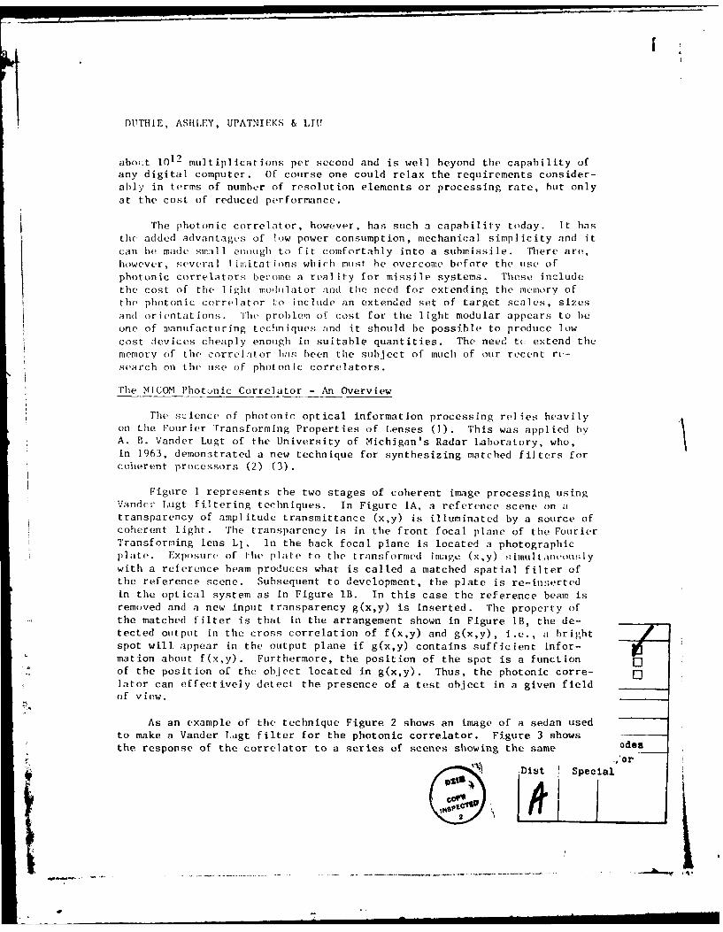
Figure I represents the two stages of coherent image processing usingVander Lugt filtering techniques. In Figure IA, a reference scene on atransparency of amplitude transmittance (x,y) is illuminated by a source ofcoherent light. The transparency is in the front focal plane of the FourierTransforming lens LI. In the back focal plane is located a photographicpl ate. Exposure of the plate to the transformed image (x,y) s.imultank-otu.;ly
with a reference beam produces what is called a matched spatial filter ofthe reference scene. Subsequent to development, the plate is re-insertedin the optical system as In Figure lB. In this case the reference beam isremoved and a new input transparency g(x,y) is inserted. The property of
the matched filter is that in the arrangement shown in Figure IB, the de-tected output in the cross correlation of f(x,y) and g(x,y), i.e., a brightspot will appear in the output plane if g(x,y) contains sufficient infor-mation about f(x,y). Furthermore, the position of the spot is a functionof the position of the object located in g(x,y). Thus, the photonic corre-lator can effectively detect the presence of a test object in a given fieldof view.
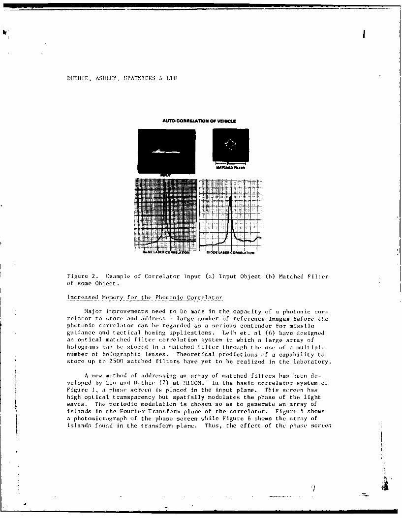
As an example of the technique Figure 2 shows an image of a sedan usedto make a Vander Lagt filter for the photonic correlator. Figure 3 showsthe response of the correlator to a series of scenes showing the same odes
DIst S .,orDlt}Special
: " I

Dl'THTIL, ASHT.EY, UPATNIEKS & ,111
vehicle driving along a highway. The lower set of photographs show the re-sponse of the photonic correlator to the input scenes. A bright correlationspot appears in the output. The existence of this spot identifies the ex-istence of the automobile in the input scene and the position of the spotdenotes the position of the automobile. In a dynamic situation the phL-
tonic correlator follows the target at T.V. frame rates.
)HERENT MATCHED FILTER OPTICAL CORRELATION
~ \ ,&SER
J REkRIEN¢E
hFRNE INPUT ft4.yl
I "ER Lf
L-
Figure 1. Typical Optical Correlator (A) Method of Recording Filters, (B)Method of Obtaining Correlations.
Real-time applications of the photonic correlator were demonstrated byGuenther et. al (4) of MICOM by utilizing a liquid crystal light modulatorto generate the spatially coherent input scene. This enahled the correlaLouto recognize and track targets at about T.V, frame rates. In 1980, Duthie
et. al (5) also of MICOM reported a further improvement in the photoniccorrelator, namely, the use of solid state laser diodes rather than bulky,fragile gas lasers. The combination of the use of real-time input devices
and solid state light sources spurred interest in developing a compactcorrelator as a practical tracking seeker. Figure 4 shows a possible con-
figuration of such a system.
• --- - - - - -l I I I "
DUTHIE, ASHLLEY, UPATNIEKS & IAU
AUTO-CORRELATION OF VEHICLE
'4D-
N- LASER ONNELATION
Figure 2. Example of Correlator Input (a) Input Object (b) Matched Filterof some Object.
Increased Memory for the Photonic Correlator
Major improvements need to be made in the capacity of a photonic cor-relator to store and address a large number of reference images before thephotonic correlator can be regarded as a serious contender for missileguidance and tactical homing applications. Leib et. al (6) have designd
an optical matched filter correlation system in which a large array ofholograms can hie stored in a matched filter through the use of a multiplenumber of holographic lenses. Theoretical predictions of a capability tostore up to 2500 matched filters have yet to be realized in the laboratory.
A new method of addressing an array of matched filters has been de-veloped by Liu and Duthie (7) at MICOM. In the basic correlator system of
Figure 1, a pha,,,e screen is placed in the input plane. This screen hashigh optical transparency but spatially modulates the phase of the light
waves. The periodic modulation is chosen so as to generate an array ofislands in the Fourier Transform plane of the correlator. Figure 5 shows
a photomicrograph of the phase screen while Figure 6 shows the array of
islands found in the transform plane. Thus, the effect of the phase screen
zI

DUTHIE, ASttLEY, UPATNIEKS & LIU
is to modify the light distribution in the back focal plane of the trans-form lens so that instead of a single spot, an array of spots is producedby a collimated input beam. In the present case, it has been found thata 5 x 5 array of spots can be engineered to carry the bulk of the lightintensity.
VEHICLE TRACKING WITHLASER DIODE CORRELATOR
Figure 3. Tracking of Automobile using Optical Correlator
Furthermore, Liu and Duthie have demonstrated that at each spot, amatched filter, of the Vander Lugt type, can be located. These workers havedemonstrated the effectiveness of each of the 25 spots individually attarget identification and tracking.
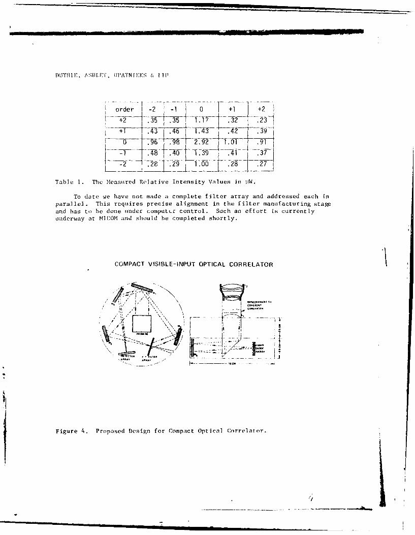
Table I shows the m(.asured intensities of the spots in the 5 x 5 array.The central (0,0) spot is certainly the brightest. The remainder, althoughnot strictly equal are indeed equal to within an order of magnitude. Auto-correlations have been measured for matching input scenes with recordedfilters of the same scene for each of the spots addressed individually.Previous work at MICOM has indicated that up to eight matched filters can berecorded at every spot or island in the Transform Plane, Thus, the poten-tial exists for the storage of tip to 200 matched filters in this system.
,14- .--.--- -- . .L
DUT!IV, AS11,F), UPATNIEKS & 111
order -2 -1 +2
+1 .43 .46 1.43 .42 -39-
--0 .96 .98 2.92 1.01 .911 .48 .40 139 41 .3-7
-2 28 .29 1 00 .28
Table 1. The Measured Relative Intensity Values in lAW.
To date we have not made a complete filter array and addressed each inparallel. This requires precise alignment in the filter manufacturing stagand has to be done under computLr control. Such an effort is currentlyunderway at MICOM and should be completed shortly.
COMPACT VISIBLE-INPUT OPTICAL CORRELATOR
Figure 4. Proposed DesgnorompctOp l . e - -- -
Figure 4. Proposed Design for Compact Optical Correlator.

DUTHIE, ASHLEY, UPATNIEKS & LIU
Figure 5. Photomicrograph of Phase Screen used to Multiplex the Number ofFilters Addressed in Parallel. Period = 1/133 inches.
Non-Coherent I 1luminat ion
Whereas the optical correlator relies on the Fourier Transforming Pro-perties of Lenses and requires good spatial coherence of the illuminatingbeam, no requirements are needed for temporal coherence of the light source.indeed, several advantages may accrue if the laser or laser diode in thephotonic correlator could he replaced by a thermal light source. Firstwould be the advantage of cost, followed by advantage in terms of theabsence of coherent or artiface noise. This noise is a direct consequenceof the temporal and spatial coherence of the source and can be eliminated
by using a broad hand light source.
There is, however, a major problem in using a thermal source. The
Fourier Transforming Properties of Lenses is a function of the wavelengthof the light used. Thus, if a broad spectral source is used to read out amatched filter, then it will only be able to form a correlation over avery
narrow band of wavelergtbs close to the wavelength used in making the
filter. For example, Figure 7 shows the Fourier Transform of a

MITlItE, ASHIY, UI'ATNIIEKS & LIU
2-Dimensional Ronchi Crating when viewed in a coherent image processingsystem when illuminated by white light.
Instead of a set of discrete spots on a rectangular array, the lens
generates a set of rainbow colored lines showing. extreme chromaticity inthe Fourier Tran'-forming function
ARRAY OF MATCMID FILIFR 'MANDS
IN FOURIER TRRJSFOu PLANE
M0b XIIXED Hn4L[I IAf'IIC FII RI' THMA" NOLO0;RAPI SCEE.NS
Figure 6. Array of Spots or Islards in the Transform Plane Produced by the
Phase Screen. At each Spot in the Central 5 x 5 Region up to Eight MatchedFrIters can be Stored and Addressed in Parallel.
A solution to this problem has been developed at the University of
Rochester (8) and has been improved on by Duthie and Upatnieks at MICOM.
The optical arrangement is shown in Figure 8. The transforming process of
a simple lens has been replaced by a train of two off axis holographic
lenses, a simple refractive lens and a diffraction grating, The first lens
is a combination of a thin lens of focal length Fo and an off axis holo-
graphic lens of focal length - F. at a wavelength ,. At other wavelengths
it has a focal length - F° X(/A. At Xo the effect of this lens is to dif-
fract an input collimated into a collimated beam at an angle to the opticalaxis. At larger and shorter wavelengths the diffracted beams diverge or
0
'i _ - 1

PIT1THIE, ASHLEY, UPATNIEKS & L.U
Figure 7. Conventional White
Light Fourier Transform of a
2-Dimensional Ronchi (Grating.Note the Extended Nature ofthe Individual Orders due to
Severe Chromait Ic ffects.
Figure 8. Optical Arrangement for Achromatic Fourier Transform System. ! ! ,

DUTH IF., ASULEY, 11PATNIEKS & LTU
converge according to wavelcngth. The grating serves to deflect the beamsback onto thc converging holographic lens L2 which has a focal length+ Fo ) ,I .The net eff.ct of these diffractions and propagations of the.waves is to generate on tihe focal plane a Fourier Transform which is, to ahigh approximation, independent of wavelength. Figure 9 shows the FourierTransform in white light obtained of the same 2-Dimensional Ronchi Gratingas used for Figure 7. The chromaticity in the Fourier Transform plane hasbeen effectively removed.
Figure 9. White Light Fouri,.rTransform of 2-DimensionalRonchi Grating using Opt icalArrangement of Figure 8.
This type of optical arrangement has been effectively used to generateauto correlations between input and identical reference scenes. An addi-tional element needs to be added to the system to make the final corre-lation achromatic - in this case a simple diffraction grating was used.
Results -;o, far have, ; own a dramatic improvemeit t in th' ;itpp;iellt -ig, ,to noise of correlations obtained using white light rather than laser lightin the achromatic correlator. Apart from the data and noise in tile inputscene, none of the other noise in the system was transformed achromat icai lyand thus did not correlate over the entire spectrum of the source used - inthis case a high intensity ltg vapor lamp.
Conclusions
7 Experiments have been performed which indicate a means to extend sig-nificantly the number of matched filters which can be simultaneously ad-dressed in the photonic correlator. Results indicate that a total of 200independent images of the target can be interrogated in parallel .
" Ic-I I

DiU1tlIE, tStIILI.Y, UPAT'NI]EKS 6 LAU " ...
Ihis c.orrc(spon(ls to in ',, fcct iv- computat ion of over 1 complex multi-p! ict ionl; pc, r s., ckrtol. 1h au', tist ,d method is mechanical Ily simplIc, op-
tical I ' easy to imp], rt' , * r qu i rs I itt le power and can be fabricate,' I[o
a compac t tin i t
Tmproveient in the 2 ignal to, noise of a photonivc correlator can b
achievtd by usini ,in achro,.it i c transform system and a thermal light s¢ource.At this time, however, tile- Lhroughput of such a system is not sufficilent tomake a practical device. Wherea.s, efforts should continue to develop tech-niques to correlate using thermal light sources, the principal thrust formaking a field operational system should, at this time, bf, concentrated onthe use of laser diode sources together with the use of phase screens toextend the memory of these systems.
REER CES
. tfor Ixampl e , J . . Goodman, I nt oduc t ion to tuir ier )ptt i us;iLCrraw-lliI , (I 98).
2. A. B. Vander Lugt, "Signal Detection by Complex Spatial Filtering",;\A;tar Lab Report 4504-22-T, (1063).
3. A. B. Vander I.ut, "Signal Detection by Complex Spatial Filtering'",I IIl cans. l trm. Theory, IT-i:_, (1964).
4. B. ). (;uenther, C. R. Christensen and J. ITpaItn i.cks, "toherent Optical
Proces;ing: Another Approach", IEEE .1. Quantum Electronics., WE-1S, 1348,1979).
. .( )uthic, i,. Il)at tniks , C. R. Christensen, and R . D. ,lhKet'zi,"Real rins Optical (orrelation with Solid State Sources", SPIl 231, 281,(198o).
6. K. G. Leib, R. A. Bondurant, M. R. Wohlers, "Optical Matched FilterCorre-lator Memory Techniques and Storage Capacity", Opt. Engr. 9, 414,(1980).
7. H. K. LiU and J. C. Iuthie, "Real Time Screen Aided Multiple ImageOptical Holographic Matched Filter Correlator", submitted for publication,Applied Optics, 1982
8. C. M. Morris, "Diffr;wtion Theory from Achromatic Fourier Transfor-mation", Appl. Opt. _1, 1255 (1972).
t i-, - i
ATE-
ILMED