Embed Size (px)
Citation preview
I »JH-^M-l^tMi.JJJ.-^-^.-ULl .... .1. m, m ,g.im9m. in u « ■ . ■•
AD-A008 893
»: I' t
LOW-COST JET FUEL STARTER DESIGN STUDY
A. Gabrys, et al
Teledyne CAE
Prepare d for:
Air Force Aero Propulsion Laboratory
2 Dece mber 1974
DISTRIBUTED BY:
Knü National Technical Information Service U. S. DEPARTMENT OF COMMERCE
_^ _^ __-^-__M4—,
=^/ D O NOTICE
When Government drawings, specifications, or other data are used for any purpose other than in connection with a definitely related Government procure»ant operation, the United States Govern»*»!*- thereby incurs no responsibility nor any obligation whatsoever; and the fact *,hat the government may have formulated, fur- nished, or in aay waj' supplied the said drawings, specification, or other data, is not to be r£tt*uded by implication or otherwise as in any manner licensing the holder or any other person or corporation, or conveying any rights or permission
Lto manufacture, use, or sell any patented invention that may in any way be related thereto.
This report has been reviewed and cleared for open publication azil/or public release by the appropriate Office of Information (01) in accordance with A7R 190- 17 and DODD 5230.9- There is no objection to unlimited distribution of this report to the public at large, or by DEC to the National Technical Information Service (NTIS).
This technical report has been reviewed and is approved for publication.
John G. Grelck III, 1 Lt., USAF Project Engineer
FOR THE COMMANDER
Buryl L. McFadden Technical Area Manager
Copies of this report should not be returned unless return is required by security considerations, contractual obligations, or notice on a specific document.
AIR FORCE/567tO/23 April 1875 - SO
I'
--~-*~ "—■ MW.ip.-' W ■ '—»II- I^w^pwgfi ■ -■■ i wp
Unclassified SECURITY CLASSIFICATION OF THIS PAGE (Whmn Dmtm Entm vd)
REPORT DOCUMENTATION PAGE READ INSTRUCTIOUS BEFORE COMPLETING FORM
i MEWÖHT NUMBER
AFAPL-TP-7U-lOU
2. GOVT ACCESSION NO
4. TITLE rani* Submit)
LOW-COST JET FUEL STARTER DEf ,N STUDY
J RECIPIENT'S CATALOG NUMBEI
TYPE OF REPORT 4 PERIOD COVERED 5 TYPE OF REPORT 4 PERIOD COVERED
Technical Report (F5nal) 1 May 1971* - 2 December 197L
6 PERFORMING ORG. REPORT NUMBER
Teledyne CAE Report No. 7. AUTHORf«;
A. Gabrys, R. Smith, et al.
■ . CONTRACT OR GRANT NUMBERf.)
F33615-Tl-C-20l4l
» PEProRMING ORGANIZATION NAME AND ADDRESS
Teledyne CAE Toledo, Ohio 1+3612
10 PROGRAM ELEMENT. PROJECT, TASK AREA 4 WORK UNIT NUMBERS
ProJ. 31^5 Task 3U501 W.U. 311*50112
It. CONTROLLING OFFICE NAME AND ADDRESS
Air Force Aero Propulsion Lab (POP) rfright-Patterscn Air For .e Base, Ohio 1*51*33
U REPORT DATE
2 December 197^ 13. NUMBER OF PAGES
Al Ü '■* MONITORING AGENCY NAME 4 AODRESSf'.' dillerenl from Controlling Cilice) IS. SECURITY C15ASS. (ol thlm report)
Unclassified IS*. OECLASSIFICATICN DOWNGRADING
SCHEDULE
16 DISTRIBUTION STATEMENT (ol Ihle Report)
Approved for public release; Distribution unlimited
17. DISTRIBUTION STATEMENT (ol the mbelrtcl entered In Slock 30, II dlllerent from Report)
18 SUPPLEMENTARY ;.OTES
TOES SUIJKT TO CHA!
i D D C
MIL
APR 3Ü I9T5
lEBElTiJE D
u 19 KEY WORDS (Continue on reverse aide it neceeemry mnd Identity by block number)
Jet Fuel Starter Free Pover Turboshaft Pinned Construction Die Cast Rotors
Electronic Fuel Control Sump & Oil Mist Lubrication Annular Vaporizer Combustor
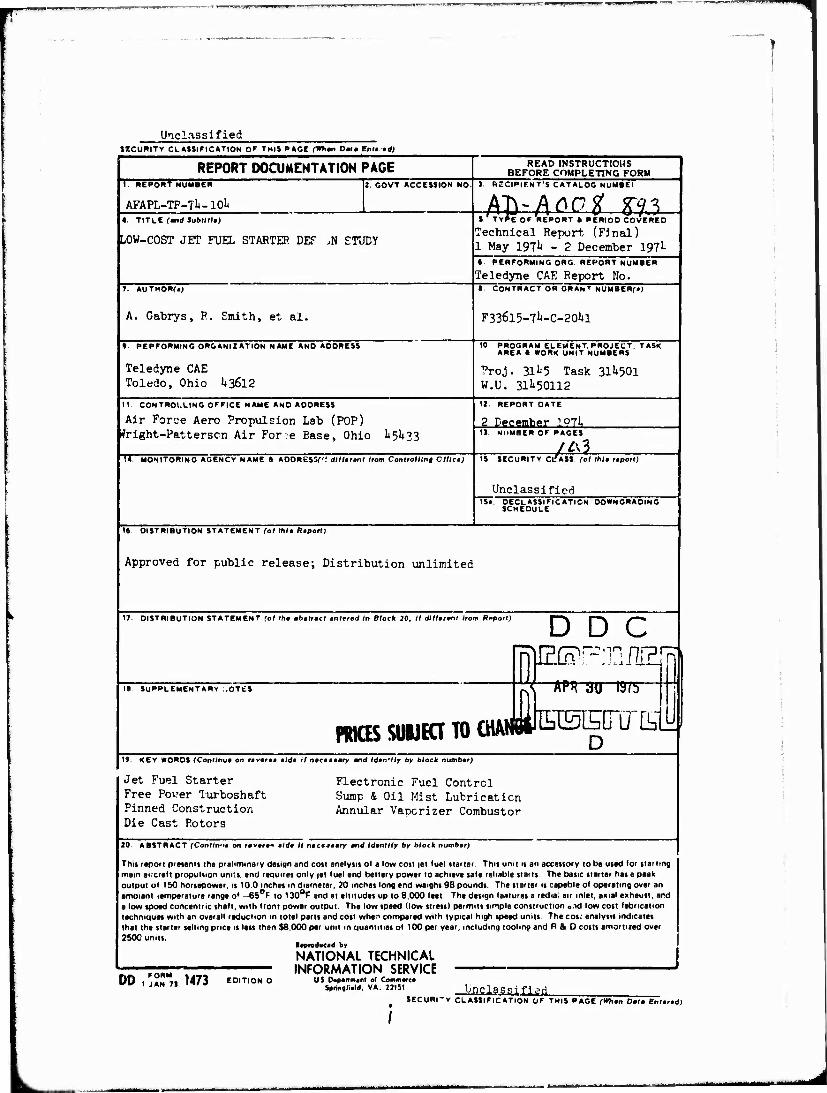
20. ABSTRACT (Continue on revere* tide It neceeemry mnd Identity by block number)
This report presents the preliminary design and cost analysis of a low cost jet fuel starter. This unit is an accessory to be used for starting main aircraft propulsion units, end requires only jet fuel and battery power to achieve safe reliable starts The basic starter has a peak output of 150 horsepower, is 10.0 inches in diameter, 20 inches long and weighs 98 pounds. The starter is capable of operating over an ambient temperature range of 65°F to 130°F and at altitudes up to 8,000 feet. The design features a radia: air inlet, axial exhaust, and a low spoed concentric shaft, with front power output. The low speed (low stress) permits simple construction o/id low cost fabrication techniques with an overall reduction in total parts and cost wher> compared with typical high speed units The cos; analysis indicates that the starter selling price is less than $8,000 per unit in quantities of 100 per year, including toolmo and RAO costs amortized over 2500 units.
»produced by
NATIONAL TECHNICAL INFORMATION SERVICE
US Dopertmonl of Commerce Sprinoliold. VA. 22131 Linda SSJ f j gd,
SECURI-Y CLASSiriCATION OF THIS PAGE fWion Detm Entered)
DD,: rORM AN 7] 1473 EDITION O
FOREWORD
This is the final Technical Report prepared "by Teledyne CAE. The effort was sponsored by the Air Force Aero Propulsion Laboratory, Air Force Systems Command, Wright-Patterson AFB, Ohio under Contract No. F336l5-71+-C-20«1 for the period 1 Mav 197** to 2 December 197**. The work herein was accomplished under
Project 311*5, Task 01, Work Unit Number 12, with Lt. John G. Grelck III, AFAPL/ P0P-1, as Project Engineer. Mr. A. Gabrys and R. Smith of Teledyne CAE were technically responsible for the work.
iii
pu^-U-iHJ ■■■! I .^WWP
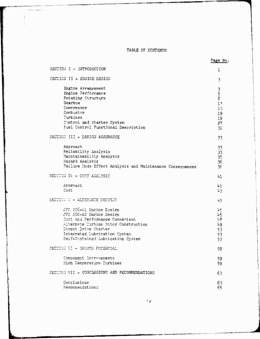
TABLE OF CONTENTS
Page No.
SECTION I - INTRODUCTION ]_
SECTION II - ENGINE DESIGN 3
Engine Arrangement 3 Engine Performance 5 Rotating Structure g Gearbox 13 Compressor 13 Combustor 19 Turbines 19 Control and Starter System 27 Fuel Control Functional Description 31
SECTION III - DESIGN ASSURANCE 33
Approach 33 Reliability Analysis 33 Maintainability Analysis 35 Hazard Analysis 36 Failure Mode Effect Analysis and Maintenance Consequences 36
SECTION IV - CCST ANALYSIS Li
Approach Ul Cost U3
SECTION" V - ALTERNATE DESIGN'S k$
JFS 2C6-A1 Engine Design 1*5 JFS 206-A2 Engine Design U5 Cost and Performance Comparison UP Alternate Turbine Rotor Construction L9 Direct Drive Starter 53 Integrated Lubrication System S3 Self-Ccntained Lubrication System 53
SECTION' VI - 3R0WTK POTENTIAL 59
Component Improvements 59 High Temperature Turbines 59
SECTION VII - CONCLUSIONS AND RECOMMENDATIONS 63
Conclusions 63 Recommendations 6s
■■■
7
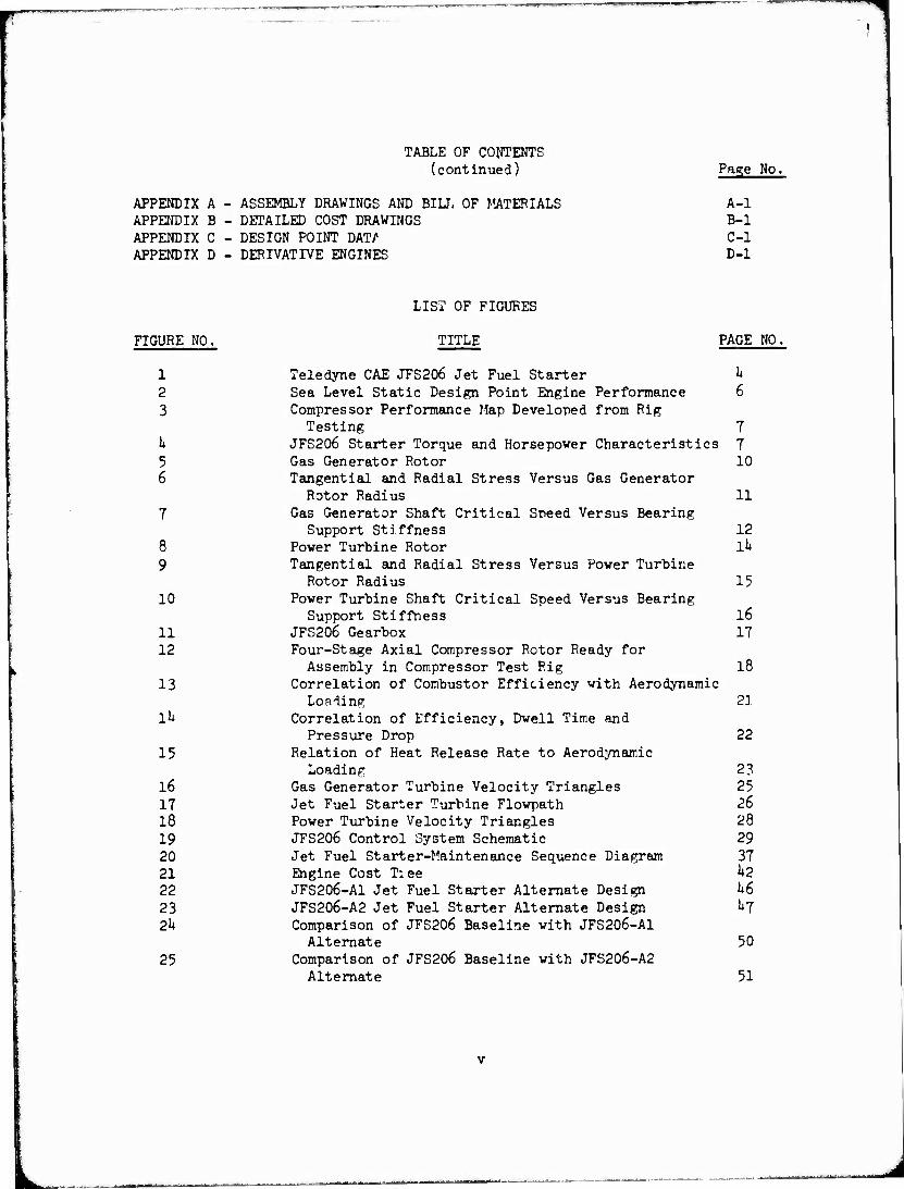
TABLE OF CONTENTS (continued) Page No.
APPENDIX A - ASSEMBLY DRAWINGS AND BILL OF MATERIALS A-l APPENDIX B - DETAILED COST DRAWINGS B-l APPENDIX C - DESIGN POINT DAT/1 C-l APPENDIX D - DERIVATIVE ENGINES D-l
LIST OF FIGURES
FIGURE NO. TITLE PAGE NO.
1 Teledyne CAE JFS206 Jet Fuel Starter k 2 Sea Level Static Design Point Engine Performance 6 3 Compressor Performance Map Developed from Rig
Testing 7 k JFS206 Starter Torque and Horsepower Characteristics 7 5 Gas Generator Rotor 10 6 Tangential and Radial Stress Versus Gas Generator
Rotor Radius 11 7 Gas Generator Shaft Critical Speed Versus Bearing
Support Stiffness 12 8 Power Turbine Rotor lk 9 Tangential and Radial Stress Versus Power Turbine
Rotor Radius 15 10 Power Turbine Shaft Critical Speed Versus Bearing
Support Stiffness l6 11 JFS206 Gearbox 17 12 Four-Stage Axial Compressor Rotor Ready for
Assembly in Compressor Test Rig 18 13 Correlation of Combustor Efficiency with Aerodynamic
Loading 21 Ik Correlation of Efficiency, Dwell Time and
Pressure Drop 22 15 Relation of Heat Release Rate to Aerodynamic
Loading 2?, 16 Gas Generator Turbine Velocity Triangles 25 17 Jet Fuel Starter Turbine Flowpath 26 18 Power Turbine Velocity Triangles 28 19 JFS206 Control System Schematic 29 20 Jet Fuel Starter-Maintenance Sequence Diagram 37 21 Engine Cost T:ee k2 22 JFS206-A1 Jet Fuel Starter Alternate Design h6 23 JFS206-A2 Jet Fuel Starter Alternate Design 1+7 2k Comparison of JFS206 Baseline with JFS206-A1
Alternate 50 25 Comparison of JFS206 Baseline with JFS206-A2
Alternate 51
LIST OF FIGURES (continued)
■ """*■
"IJURE NO,
26
21
28 29 30
31
32
33
A-2 A-3 A-J» A-5 A-6 A-7 A-8 A-9 A-IO
:hru 3-9
,-1 3-2
TITLE PAGE NO.
JFS206 Alternate Gas Generator Turbine Rotor Construction 52
JFS206 Alternate Power Turbine Rotor and Shaft Construction 52
Direct Drive Starter with Integrated Lube System 5h External Fuel Supply to Pun Bearings 55 Direct Drive Starter Torque and Horsepower
Characteristics 56 Direct Drive Starter with Self-Contained
Lubrication System 57 Effect of Increased Turbine Inlet Temperature
on Engine Output Horsepower 6l JFS206 Jet Fuel Starter 6h Model JFS206 Engine Assembly (Elevation) A-2 Model JFS206 Engine Assembly (End View) A-3 Model JFS2C6 Engine Assembly (Section A-A) A-1+ Model JFS206 Engine Assembly (Bill of Materials) A-5 Model JFS206-A1 Engine Assembly (Elevation) A-6 Model JFS206-A1 Engine Assembly (End View) A-7 Model JFS206-A1 Engine Assembly (Bill cf Materials) A-8 Model JFS206-A2 Engine Assembly (Elevation) A-9 Model JFS206-A2 Engine Assembly (End View) A-10 Model JFS206-A2 Engine Assembly (Bill of Materials) A-ll Detailed Cost Drawings B-2 to B- Model JFS206 Jet Fue] Starter Design Point Data C-2 Model JFS206-A1 and 206-A2 Alternate Designs
Desirn Point Data C-3 Turbojet Derivative of Jet Fuel Starter D-2 Turbofan Derivative of Jet Fuel Starter D-U
LIST OF TABLES
2 3 k
5 6
TITLE
JFS206 Combustor Parameters Turbine Aerothermodynamic Requirements Jet Fuel Starter Reliability Prediction Failure Mode Effect Analysis and Maintenance
Consequence Labor and Material for JFS206 Sea Level Design Point Engine Performance Characteristics
PAGE NO.
2G 27 3^
38 & 39
60
vi
WflU I
LIST OF TABLES (continued)
TABLE NO,
7 D-l I>-2
TITLE PAGE NO,
Sea Level Design Point Component Improvements 60 Turbojet Performance Summary D-3 Turbofan Performance Summary D-5
vii
1
SECTION
INTRODUCTION
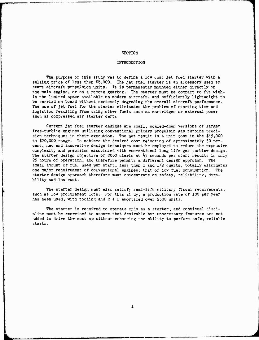
The purpose of this study was to define a low cost Jet fuel starter with a selling price of less than $8,000. The Jet fuel starter is an accessory used to start aircraft propulsion units. It is permanently mounted either directly on the main engine, or on a remote gearbox. The starter must be compact to fit with- in the limited space available on modern aircraft, and sufficiently lightweight to be carried on board without seriously degrading the overall aircraft performance. The use of Jet fuel for the starter eliminates the problem of starting time and logistics resulting from using other fuels such as cartridges or external power such as compressed air starter carts.
Current Jet fuel starter designs are small, scaled-down versions of larger free-turbi'e engines utilizing conventional primary propulsin gas turbine preci- sion techniques in their execution. The net result is a unit cost in the $15,000 to $20,000 range. To achieve the desired cost reduction of approximately 50 per- cent, new and innovative design techniques must be employed to reduce the expensive complexity and precision associated 'rith conventional long life gas turbine design. The starter design objective of 2000 starts at 1*5 seconds per start results in only 25 hours of operation, and therefore permits a different design approach. The small amount of fue. used per start, less than 1 and 1/2 quarts, totally eliminate? one major requirement of conventional engines; that of low fuel consumption. The starter design approach therefore must concentrate on safety, reliability, dura- bility and low cost.
The starter design must also satisfj real-life military fiscal requirements, such as low procurement lots. For this st \dy, a production rate of 100 per year has been used, with tooling and R&D amortized over 2500 units.
The starter is required to operate only as a starter, and continual disci- pline must be exercised to assure that desirable but unnecessary features are not added to drive the cost up without enhancing the ability to perform safe, reliable starts.
J
SECTION II
ENGINE DESIGN
ENGINE ARRANGEMENT
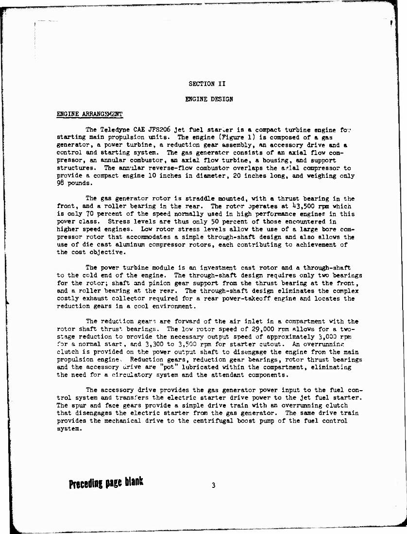
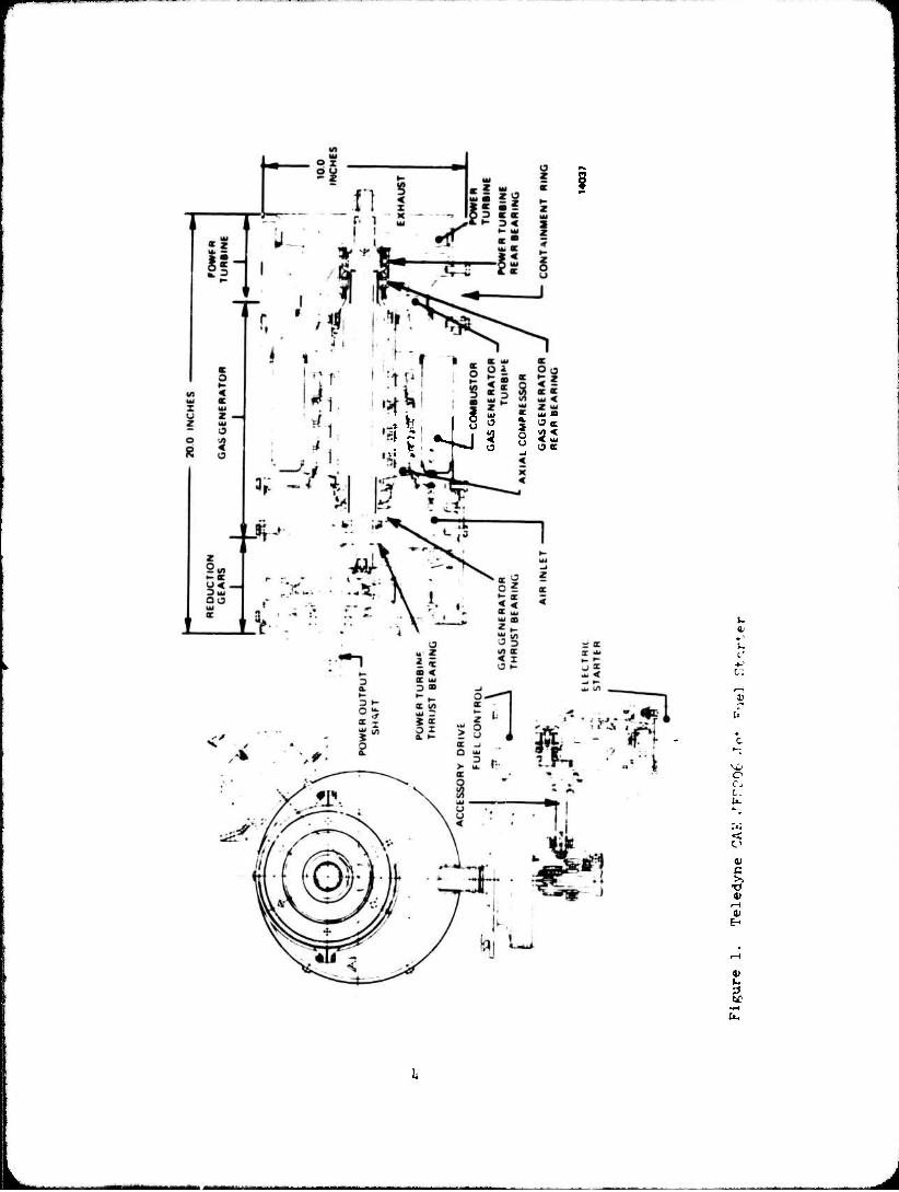
The Teledyne CAE JFS206 Jet fuel starrer is a compact turbine engine fov starting main propulsion units. The engine (Figure l) is composed of a gas generator, a power turbine, a reduction gear assembly, an accessory drive and a control and starting system. The gas generator consists of an axial flow com- pressor, an annular combustor, an axial flow turbine, a housing, and support structures. The annular reverse-flow combustor overlaps the arial compressor to provide a compact engine 10 inches in diameter, 20 inches long, and weighing only 98 pounds.
The gas generator rotor is straddle mounted, with a thrust bearing in the front, and a roller bearing in the rear. The rotor operates at 1*3,500 rpm which is only TO percent of the speed normally used in high performance engines in this pover class. Stress levels are thus only 50 percent of those encountered in higher speed engines. Low rotor stress levels allow the use of a large bore com- pressor rotor that accommodates a simple through-shaft design and also allows the use of die cast aluminum compressor rotors, each contributing to achievement of the cost objective.
The power turbine module is an investment cast rotor and a through-shaft to the cold end of the engine. The through-shaft design requires only two bearings for the rotor; shaft and pinion gear support from the thrust bearing at the front, and a roller bearing at the rear. The through-shaft design eliminates the complex costly exhaust collector required for a rear power-takeoff engine and locates the reduction gears in a ccol environment.
The reduction gear- are forward of the air inlet in a compartment with the rotor shaft thrust bearings. The low rotor speed of 29,000 rum allows for a two- stage reduction to provide the necessary output speed of approximately 3,000 rpm for a normal start, and 3,300 to 3,500 rpm for starter cutout. An overrunning clutch is provided on the power output shaft to disengage the engine from the main propulsion engine Reduction gears, reduction gear bearings, rotor thrust bearings and the accessory urive are "pot" lubricated within the compartment, eliminating the need for a circulatory system and the attendant components.
The accessory drive provides the gas generator power input to the fuel con- trol system and transfers the electric starter drive power to the Jet fuel starter. The spur and face gears provide a simple drive train with an overrunning clutch that disengages the electric starter from the gas generator. The same drive train provides the mechanical drive to the centrifugal boost pump of the fuel control system.
Preceding page blank
1
4*1 I as i : I * l —i
J <r
32
1. :' 4-
1)
e r. t.
V
s 1-1
4)
:
J
·:~.e tn.sic ·::cr.f:!.•:ur~t:ian of ~he .1et fuel ntarter u~es low rotor sneeds which 'l::c ... · !'C'·!' Gi:::rl: fie:: l.ub!'ication s::ster.u:;. ~he bear::.ngs and gears are loca\.ed in ~he nc~ :utricnted front end with the exception of the rotor roller bea.rin~s ·.;:.:~i: :~.re ::..1l1:J!·icated by r: ',."'lSte fuel system. This combir.R.tion lubrication system :1as b-:e~ successflL.ly· der.-:o~:-:trated or. tr..e Teledyne CAE J402-CA-400 HARPOOn engine 'l.:; j "':he ·:::eled:,T.e CAE :-!odcl 373-2, '!ariable Sneed Training Tarp:et engine (VSTT) •
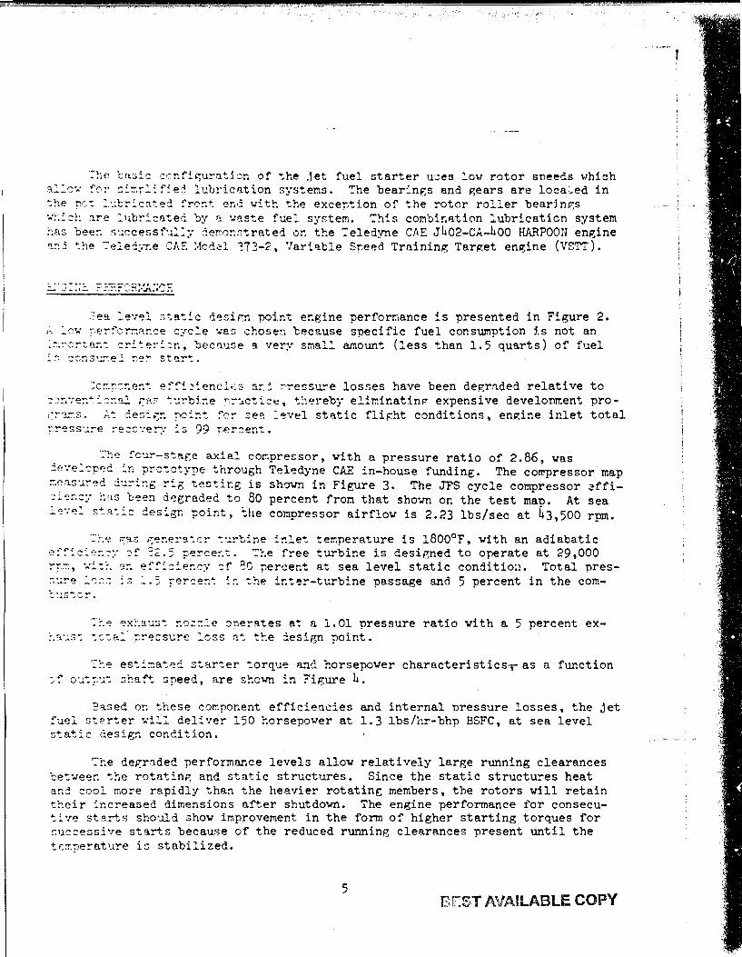
. :·ea ::.e·:'?l s-:a~ic desir:n po:!.nt er.gine perforr.,a.nce is presented in Figure 2. ,:. ::..c.,. ::-er:'c.:;::ar.ce cycle '.o.'as chosen because specific fuel consumption ;.s not an ::.::;::-cr~a::.~ cri ":e!·i.:r., bec'l'.lSe a Yer:r small amount (less than 1. 5 quarts) of fuel
::c::-.:-::-.:-.en~ e:':'i ::i encl.::: ar .: ;-·ress'l.l!"e losses have been degrn.ded relative to c~·:-.·:e::•:.::::a2. ~?.':' :'.lrbi~e '":':.tcti.ct, t:1•:reby elimir.atinp- expensive develonment pro:-::--'l::-.s. .:..: d.es:,;:::-. }10:.:::. fc:-- :::e?. ~evel st11tic flip::ht conditions, engine inlet total
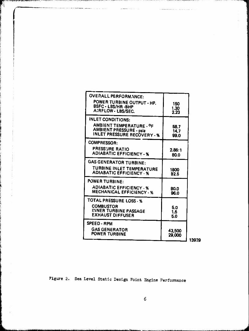
~~~ fc~-stace axial compre~sor, with a pressure ratio of 2.86, was :ie·:e::. ':lp~d .:.r: pro<:o~ype through Teledyne CAE in-house funding. The compressor map ::-.c'lsu;ed .:l'..lri::g rig tes~ir.g is shown in Figure 3. The JFS cycle compressor ~ffi::;i~_;::c:,· hr1s teen dr;e;raded to 80 percent from that shown on the test mao. At sea lr:·:~::. s~a:::c design point, ~he compressor airflov is 2.23 lbs/sec at 43,500 rpm.
:~e ~as ~enera~cr ~'..lrbine inlet temperature is 1800°F, with an adiabatic e:~~ic::.-:::-. ~:: :-f ~2. 5 ~erce:-.t. ':he free turbine is designed to operate at 29,000 r':':-:-., ·..::~:-. ar. ef~ici.er.cy 'Jf ~0 percent at sea level static conditio41. Total pres:;·ze ::..s:::: ::. s .~.; :err:e:-r: i :-: t!ie inter-turbine passage and 5 percent in the com-
:t~ e~~a'..lst no:=:e oper~tes at a 1.01 pressure ratio with a. 5 percent ex:-.a·..:.s: :::.:a::.. ::resst:.re :.ass ::.: tte design point.
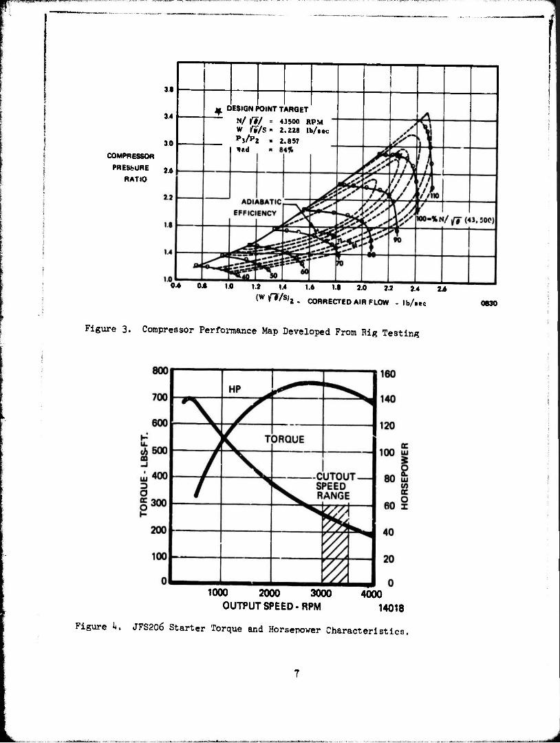
·.::te es<::::Jated starter torque a.."'ld horsepower characteristics,- as a function - .. o:.r:rj·J.: shaf:. speed, are shewn in Figure 4.
Eased or. these component efficien~ies and internal pressure losses, the jet :':lel ste.rter will deliver 150 horsepower at 1.3 lbs/hr-bhp BSFC, at sea level static design condition.
7he de~rn.ded performance levels allow relatively large running clearances tet·Jeer. the rot at in~ and static structures. Since the static structures heat and cool more rapidly than the heavier rotatinr; members, the rotors will retain their :.ncreased dimensions after shutdown. The engine performance for consecu"'::ive starts should shov improvement in the form of higher starting torques for successive starts because of the reduced running clearances present until the tc::Jperature is stabilized.
5 BEST AVAILABLE COPY
OVERALL PERFORMANCE: POWER TURBINE OUTPUT BSFC-LBS/HR-BHP AIRFLOW- LBS/SEC.
HP.
INLET CONDITIONS: AMBIENT TEMPERATURE - °F AMBIENT PRESSURE - psia INLET PRESSURE RECOVERY - %
COMPRESSOR: PRESSURE RATIO ADIABATIC EFFICIENCY %
GAS GENERATOR TURBINE: TURBINE INLET TEMPERATURE ADIABATIC EFFICIENCY - %
POWER TURBINE: ADIABATIC EFFICIENCY - % MECHANICAL EFFICIENCY - %
TOTAL PRESSURE LOSS - % COMBUSTOR INNER TURBINE PASSAGE EXHAUST DIFFUSER
SPEED-RPM GASGENERATOR POWER TURBINE
150 1.30 2.23
58.7 14.7 99.0
2.86:1 80.0
1800 82.5
80.0 96.0
5.0 1.5 5.0
43,500 29,000
13929
Figure 2. Sea Level Static Design Point Engine Performance
*1-- - - ^'«»^^- ■■ '■ -
3.1
30
COMPRESSOR
PRESSURE 2A
RATIO
M DESIGN POINT TARGET
N/ ft/ = 43500 RPM W fi/S = 2.228 lb/tec
P3/P2 * 2.857 lud «
0.6 OJ 1.0 1.2 U 1« !•• 20 22 2.4 2.4
(Wff/S)2m CORRECTED AIR FLOW - lb/»«c 0830
Figure 3. Compressor Performance Map Developed From Rig Testing
1000 2000 3000 4000
OUTPUT SPEED - RPM 14018
Figure k, JFS206 Starter Torque and Horsepower Characteristics.
jM^-jg^a:-«". ^nr ' "'"
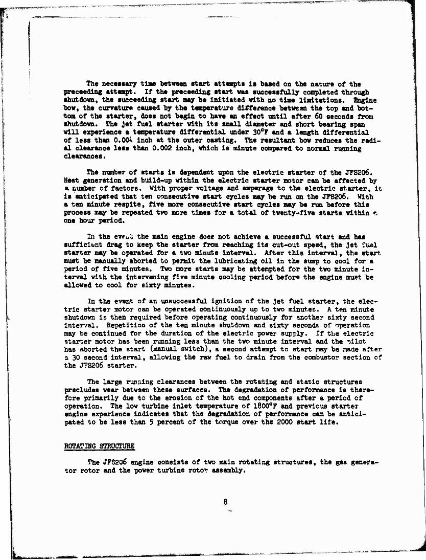
The necessary time between start attempts is baaed on the nature of the proceeding attempt. If the proceeding start was successfully completed through shutdown, the succeeding start may be initiated with no time limitations. Engine bow, the curvature caused by the temperature difference between the top and bot- tom of the starter, does not begin to have an effect until after 60 seconds from shutdown. The Jet fuel starter with its small diameter and short bearing span will experience a temperature differential under 30°F and a length differential of less than O.OOi inch at the outer casting. The resultant bow reduces the radi- al clearance less than 0.002 inch, which is minute compared to normal running clearances.
The number of starts is dependent upon the electric starter of the JFS206. Heat generation and build-up within the electric starter motor can be affected by a number of factors. With proper voltage and amperage to the electric starter, it is anticipated that ten consecutive start cycles may be run on the JFS206. With a ten minute respite, five more consecutive start cycles may be run before this process may be repeated two mere times for a total of twenty-five starts within ?. one hour period.
In the evtul the main engine doee not achieve a successful start and has sufficient drag to keep the starter from reaching its cut-out speed, the jet fuel starter may be operated for a two minute interval. After this interval, the start must be manually aborted to permit the lubricating oil in the sump to cool for a period of five minutes. Two more starts may be attempted for the two minute in- terval with the intervening five minute cooling period before the engine must be allowed to cool for sixty minutes.
In the event of an unsuccessful ignition of the jet fuel starter, the elec- tric starter motor can be operated continuously up to two minutes. A ten minute shutdown is then required before operating continuously for another sixty second interval. Repetition of the ten minute shutdown and sixty seconds of operation may be continued for the duration of the electric power supply. If the electric starter motor has been running less than the two minute interval and the nilot has aborted the start (manual switch), a second attempt to start may be made after a 30 second interval, allowing the raw fuel to drain from the combustor section of the JFS206 starter.
The large running clearances between the rotating and static structures precludes wear between these surfaces. The degradation of performance is there- fore primarily due to the erosion of the hot end components after a period of operation. The low turbine inlet temperature of l800°F and previous starter engine experience indicates that the degradation of performance can be antici- pated to be less than 5 percent of the torque over the 2000 start life.
ROTATING STRUCTURE
The JFS206 engine consists of two main rotating structures, the gas genera- tor rotor and the power turbine rotor assembly.
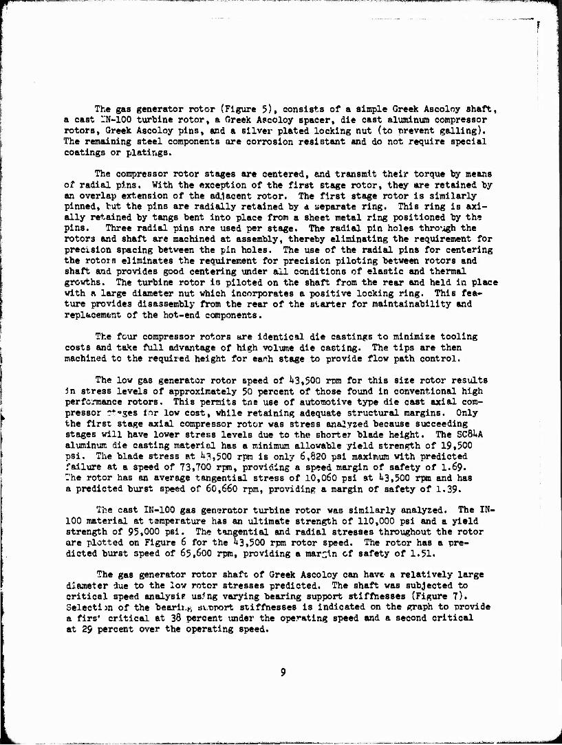
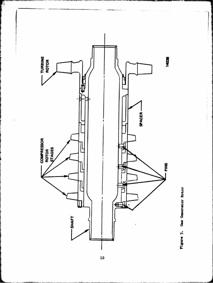
The gas generator rotor (Figure 5), consists of a simple Greek Ascoloy shaft, a cast l'N-100 turbine rotor, a Greek Ascoloy spacer, die cast aluminum compressor rotors, Greek Ascoloy pins, and a silver plated locking nut (to prevent galling). The remaining steel components are corrosion resistant and do not require special coatings or platings.
The compressor rotor stages are centered, and transmit their torque by means of radial pins. With the exception of the first stage rotor, they are retained by an overlap extension of the adjacent rotor. The first stage rotor is similarly pinned, but the pins are radially retained by a separate ring. This ring is soci- ally retained by tangs bent into place from a sheet metal ring positioned by the pins. Three radial pins are used per stage. The radial pin holes through the rotors and shaft are machined at assembly, thereby eliminating the requirement for precision spacing between the pin holes. The use of the radial pins for centering the rotors eliminates the requirement for precision piloting between rotors and shaft and provides good centering under all conditions of elastic and thermal growths. The turbine rotor ia piloted on the shaft from the rear and held in place with a large diameter nut which incorporates a positive locking ring. This fea- ture provides disassembly from the rear of the starter for maintainability and replacement of the hot-end components.
The four compressor rotors are identical die castings to minimize tooling costs and ta^e full advantage of high volume die casting. The tips are then machined to the required height for earth stage to provide flow path control.
The low gas generator rotor speed of 1*3,500 rpm for this size rotor results in stress levels of approximately 50 percent of those found in conventional high perfc.Tnance rotors. This permits tne use of automotive type die cast axial com- pressor -*oges inr low cost, while retaining adequate structural margins. Only the first stage axial compressor rotor was stress analyzed because succeeding stages will have lower stress levels due to the shorter blade height. The SCBlA aluminum die casting material has a minimum allowable yield strength of 19.500 psi. The blade stress at 1*3,500 rpm is only 6,820 psi maximum with predicted failure at a speed of 73,700 rpm, providing a speed margin of safety of I.69. The rotor has an average tangential stress of 10,060 psi at 1*3,500 rpm and has a predicted burst speed of 60,660 rpm, providing a margin of safety of 1.39«
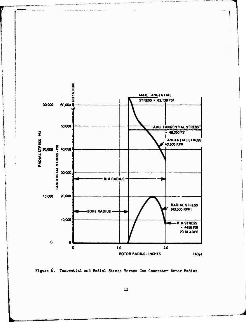
The cast IN-100 gas generator turbine rotor was similarly analyzed. The IN- 100 material at temperature has an ultimate strength of 110,000 psi and a yield strength of 95,000 psi. The tangential and radial stresses throughout the rotor are plotted on Figure 6 for the 1*3,500 rpm rotor speed. The rotor has a pre- dicted burst speed of 65,600 rpm, providing a margin of safety of 1.51.
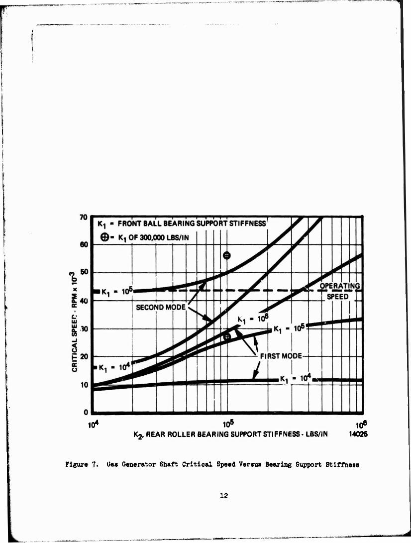
The gas generator rotor shaft of Greek Ascoloy can have a relatively large diameter due to the low rotor stresses predicted. The shaft was subjected to critical speed analysis us?ng varying bearing support stiffnesses (Figure 7). Selectijn of the bearii.ft svnport stiffnesses is indicated on the graph to provide a firs* critical at 38 percent under the operating speed and a second critical at 29 percent over the operating speed.
HPaTWff .<>>■■ ■!.: mm | I
Ö
1 s u\
10
30,000 1
eo.ocüi- ffi
«0,000
£
fc 20,000 ' 40.ow
< i IM
I K
-1
jT 30,000 z u O 2 1$
10,000 20,000
10,000
MAX. TANGENTIAL STRESS - 62,130 PS I
RIM RADIUS-
AVQ. TANGENTIAL STRESS'
48,350 PSI
TANGENTIAL STRESS" 43.500 RPM
RADIAL STRESS (43.500 RPM)
RIM STRESS - 4455 PSI 23 BLAOES
1.0 2.0
ROTOR RADIUS • INCHES 14024
Figure 6. Tangential and Radial Stress Versus Gas Generator Rotor Radius
11
10* 105 106
K2. REAR ROLLER BEARING SUPPORT STIFFNESS- LBS/IN 14025
Figure 7. Uas Generator Shaft Critical Speed Versus Bearing Support Stiffness
12

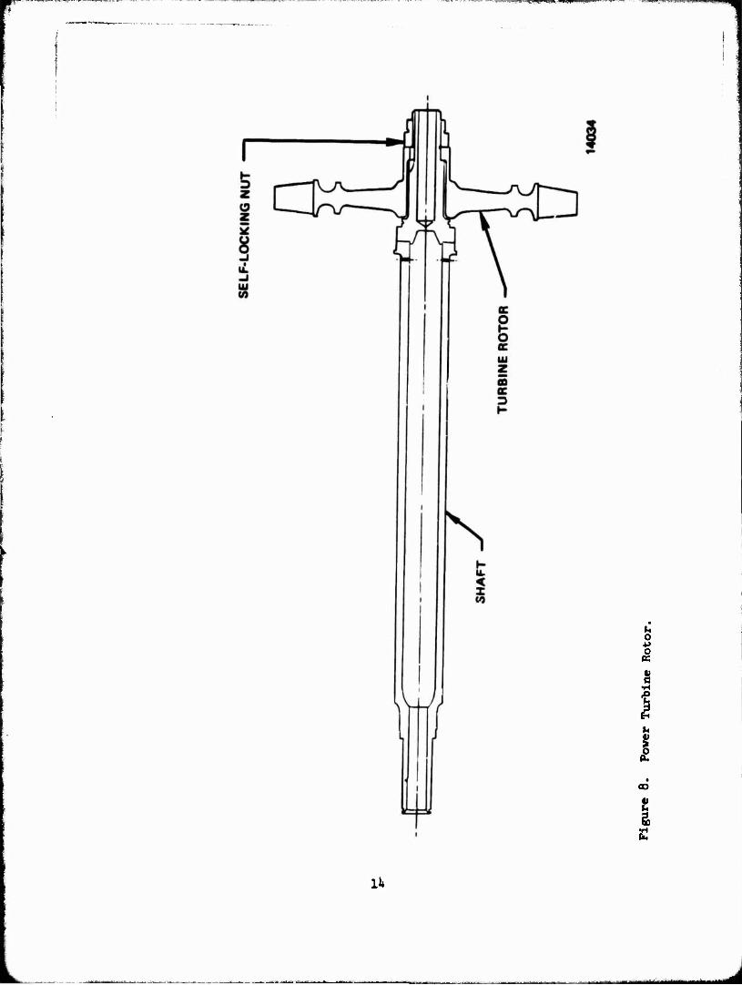
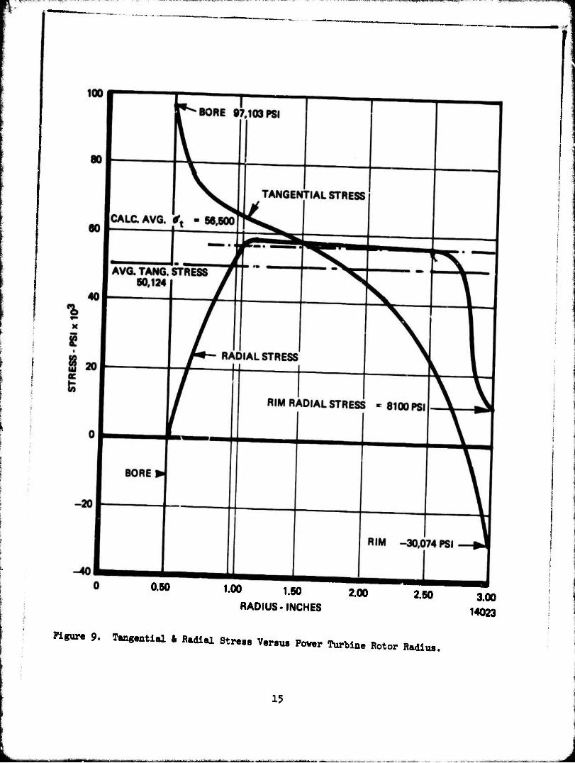
The power turbine rotor assembly (Figure 8) consists of an investment cast Inconel 713LC turbine roto- keyed to the Greek Asc^lcy shaft and retained by a self-locking nut. The stress analysis on the power turbine rotor was conducted at 30 percent over the design operating speed to allow for the overspeed condition which will occur upon disengagement of the clutch when the main engine ignites. The radial and tangential stresses versus rotor radius are plotted on Figure 9 for 37*700 rpm. The rotor has a predicted burst speed of 5^.600 **pm which provides a mu*gin of safety of 0,88 over design speed and a margin of safety of 0.1(5 for the 30 percent overspend.
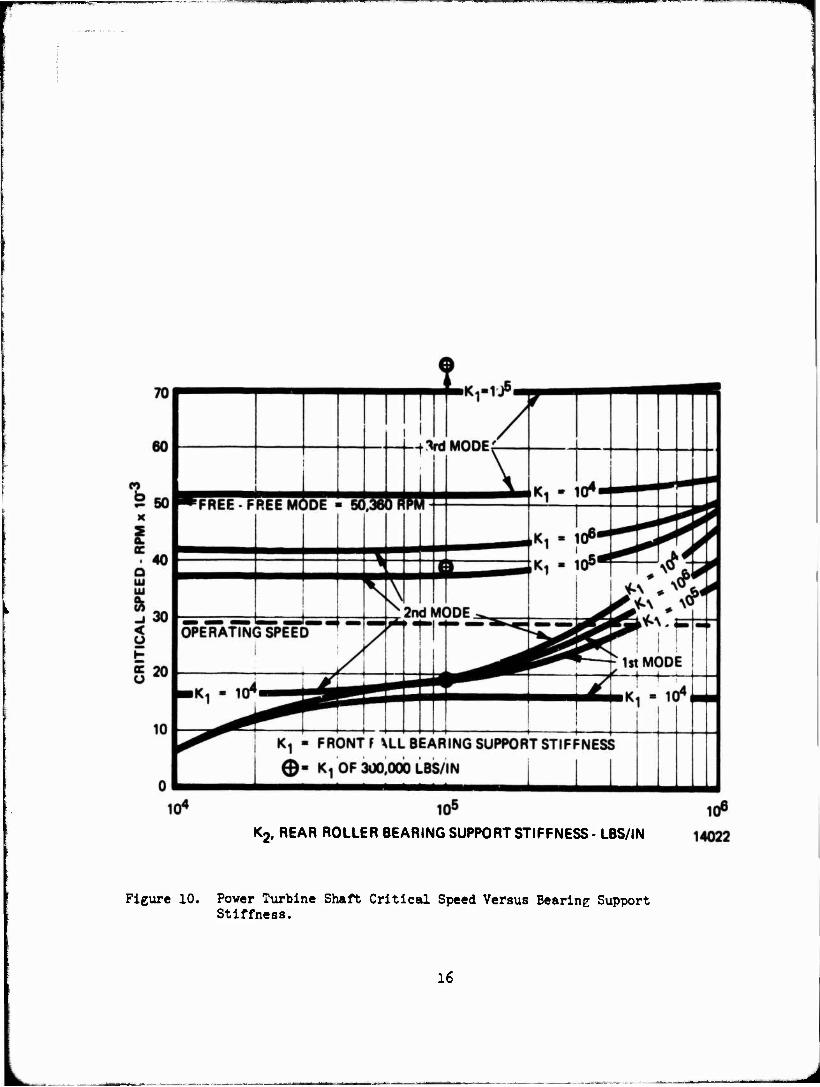
The power turbine Greek Ascoloy shaft was subjected to critical speed analy- sis using varying bearing support stiffnesses with the results plotted on Figure 10. Selection of the bearing support stiffnesses similar to those used for the gas generator shaft is indicated on the graph. These stiffnesses indicate that the first critical occurs 31* percent under the operating speed« and the second critical occurs 3h percent over the operating speed.
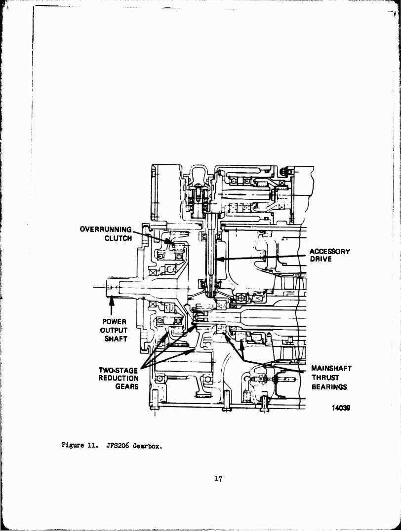
GEARBOX
The gearbox of the jet fuel starter (Figure 11) consists of the two-stage reduction gearing, the overrunning clutch, the power output shaft, the accessory drive train,, the main shaft thrust bearings, the gear bearings and the lubrica- tion system, all housed within the front compartments. The two gear stages pro- vide a 10:1 speed reduction to produce the necessary output speed, with peak power being supplied Just prior to the 3,000 to 3,500 rpm starter cutout. The gears have been designed, using design factors which allow for the use of un- ground gears. These gears are oversized compared to aircraft quality gears; however, the elimination of the requirements for supercritical finishes contri- butes to achieving the cost objectives.
The accessory drive train uses face and spur gear sets which eliminate the critical alignment problems associated with bevel gear sets. Machining of the housing is facilitated by these lessened requirements. The low rotor rpm of both shafts permits the use of low speed bearings with a simplified lubrication system. All gears and bearings are splash-lubricated by the oil from the sump created by the front compartment. This lubrication system eliminates the usual pressure and scavenge oil pumps, oil lines, passages, tank Jets, coolers, filters, and regu- lating and anti-leek valves normally associated with long-life propulsion gas turbine engines.
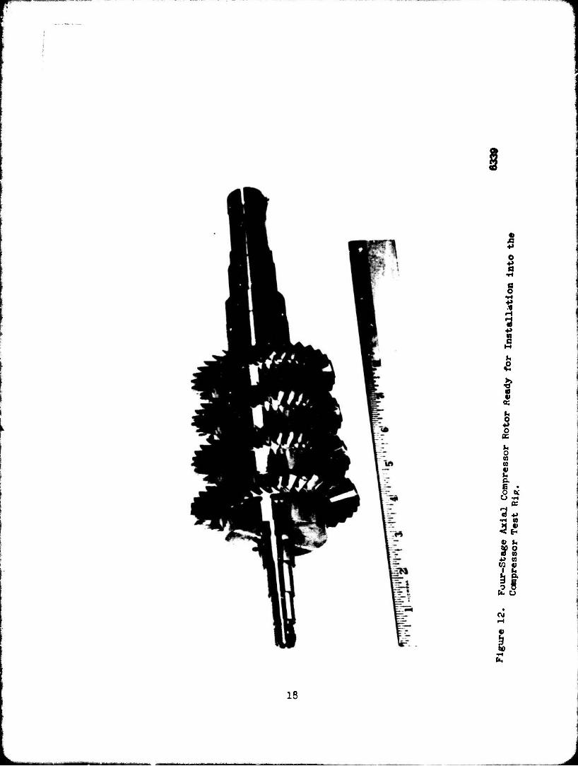
COMPRESSOR
The compressor is the heart of all gas turbine engines, and as such, is a major portion of any engine development program and is also a significant part of the recurring labor and material cost in conventional engines. The compressor for the jet fuel starter (Figure 12) is an existing Teledyne CAE design that has been fabricated and rig tested to establish its performance characteristics.
13
o
I t
oo
Ik
i^iwyiMi«! HU ii
0.60 1.00 1.50 2.00
RADIUS-INCHES 2.60 3.00
14023
Figure 9. Tangential * Radial Strass Varsus Povar Turbine Rotor Radius.
f
15
PMPggipmPVm
K2, REAR ROLLER BEARING SUPPORT STIFFNESS- LBS/IN
Figure 10. Power Turbine Shaft Critical Speed Versus Bearing Support Stiffness.
16
OVERRUNNING CLUTCH
ACCESSORY DRIVE
POWER OUTPUT
SHAFT
TWC-STAGE REDUCTION
GEARS
MAINSHAFT THRUST BEARINGS
14038
Figure 11. JFS206 Gearbox.
17
2 o $
8
2 c M
U O
f « h o o
PS
u o m a tl h & E • ,0 bC O ft
OS
3 3£
h o to CO
Ü «2
C\J
18
u.
■I ■ ■■■■
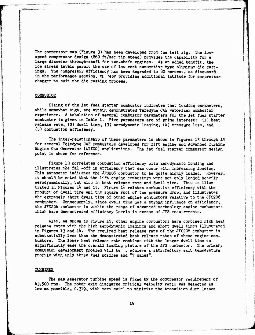
The compressor map (Figure 3) has been developed from the test rig. The low- speed compressor design (860 ft/sec tip speed) provides the capability for a large diameter throutfh-shaft for two-shaft engines. As an added benefit, the low stress levels permit the use of low cost automotive type aluminum die cast- ings. The compressor efficiency has been degraded to 80 percent, as discussed in the performance section, tt *eby providing additional latitude for compressor changes to suit the die casting process.
C0MBUST0R
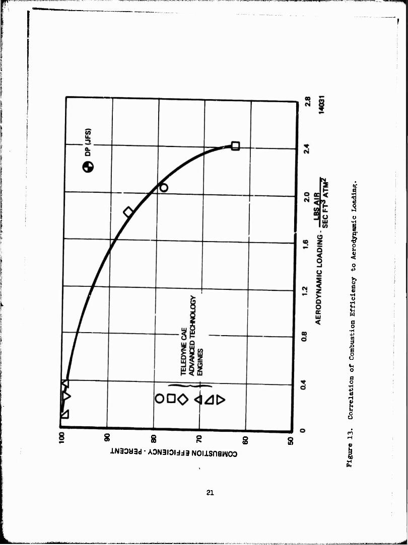
Sizing of the Jet fuel starter combustor indicates that loading parameters, while somewhat high, are within demonstrated Teledyne CAE vaporizer combustor experience. A tabulation of several combustor parameters for the Jet fuel starter combustor is given in Table 1. Five parameters are of prime interest: (l) heat release rate, (2) dwell time, (3) aerodynamic loading, (h) pressure loss, and (5) combustion efficiency.
The inter-relationship of these parameters is shown in Figures 13 through 15 for several Teledyne CAE combustors developed for lift engine and Advanced Turbine Engine Gas Generator (ATEGG) applications. The jet fuel starter combustor design point is shown for reference.
Figure 13 correlates combustion efficiency with aerodynamic loading and illustrates the fal -off in efficiency that can occur with increasing loading. This parameter indicates the JFS206 combustor to be quite highly loaded. However, it should be noted that the lift engine combustors were not only loaded heavily aerodynamically, but also in heat release rate and dwell time. This is illus- trated in Figures Ik and 15. Figure ll relates combustion efficiency with the product of dwell time and the square root of the pressure drop, and illustrates the extremely short dwell time of other engine combustors relative to the JFS206 combustor. Consequently, since dwell time has a strong influence on efficiency, the JFS206 combustor is within the range of advanced technology engine combustors vhich have demonstrated efficiency levels in excess of JFS requirements.
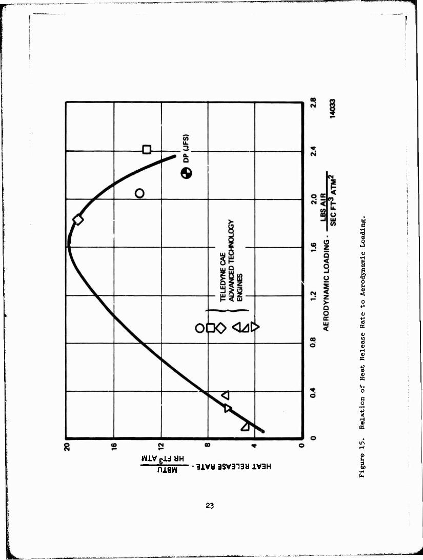
Also, as shown in Figure 15, other engine combustors have combined high heat release rates with the high aerodynamic loadings and short dwell times illustrated in Figures 13 and Ik. The required heat release rate of the JFS206 combustor is substantially less than the demonstrated heat release rates of these engine com- bustors. The lower heat release rate combines with the longer dwell time to significantly ease the overall loading picture of the JFS combustor. The primary combustor development problem will be J achieve a satisfactory exit temperature profile with only three fuel nozzles and "T canes".
TURBIHES
The gas generator turbine speed is fixed by the compressor requirement of 1»3»500 rpm. The rotor exit discharge critical velocity ratio was selected as low as possible, 0.319, with zero swirl to minimize the transition duct losses
19
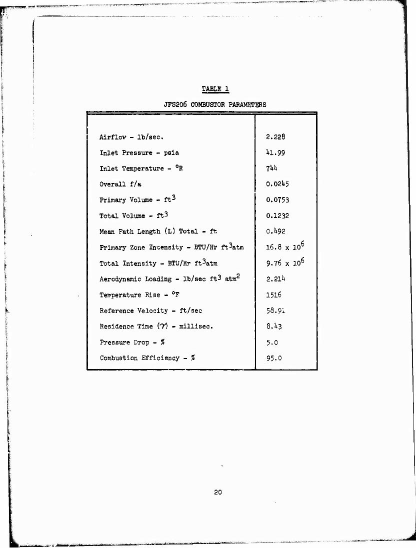
TABLE 1
JFS206 COMBUSTOR PARAMETERS
Airflov - lb/sec. 2.228
Inlet Pressure - psia 1*1.99
Inlet Temperatxire - °R fkh
Overall f/a 0.021*5
Primary Volume -ft3 0.0753
Total Volume - ft3 0.1232
Mean Path Length (L) Total - ft 0.1*92
Primary Zone Intensity - BTU/Hr ft3atm 16.8 x 10⁶
Total Intensity - BTU/Hr ft3atm 9-76 x 106
Aerodynamic Loading - lb/sec ft3 atm 2.211*
Temperature Rise - °F 1516
Reference Velocity - ft/sec 58.91
Residence Time (T") - millisec. 8.1+3
Pressure Drop - % 5.0
Combustion Efficiency - % 95.0
20
a ■H
1
8 8 g g lN30W3d ■ A0N1IDIJJ3 NOIlSOaWOO
S
o h
Ü o
& g
w
g •H
I
o d o
H
s m H v
k ■H
21
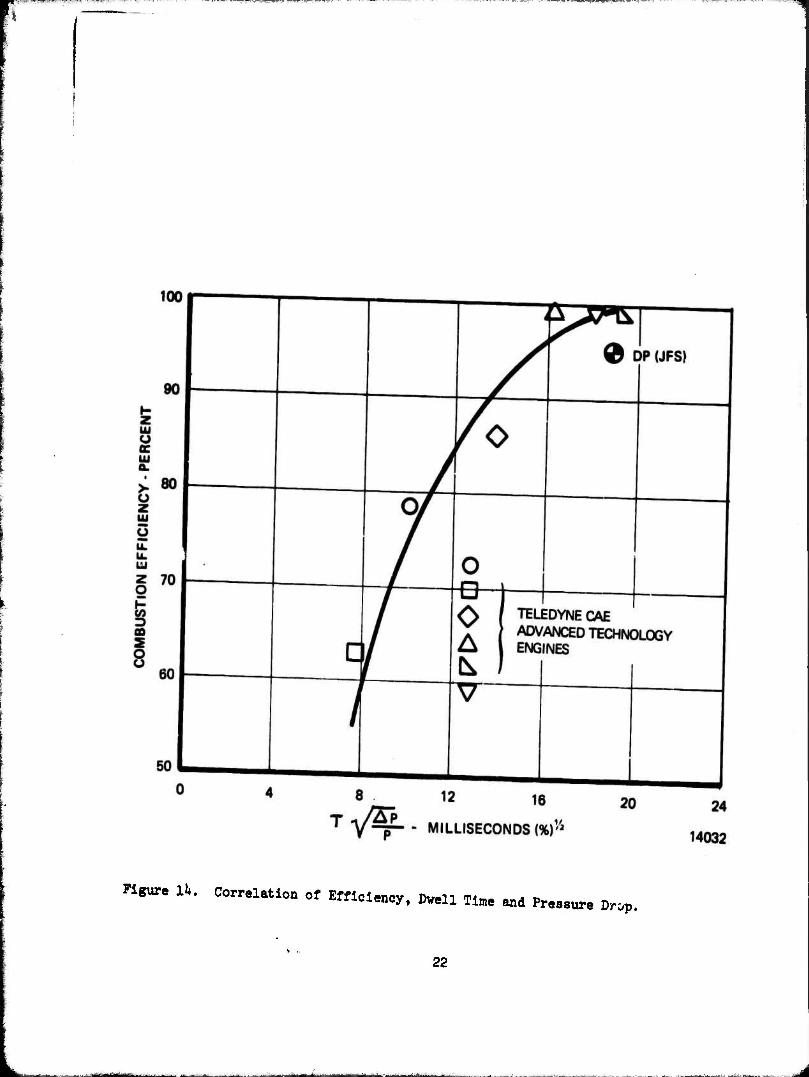
Figure 11». Correlation of Efficiency, Dwell Time and Pressure Drop.
22
a •H
a)
o ■p
n K
K
O
c o
•H
•A K
IA H
maw 3iVd 3SV313W XV3H
23
^
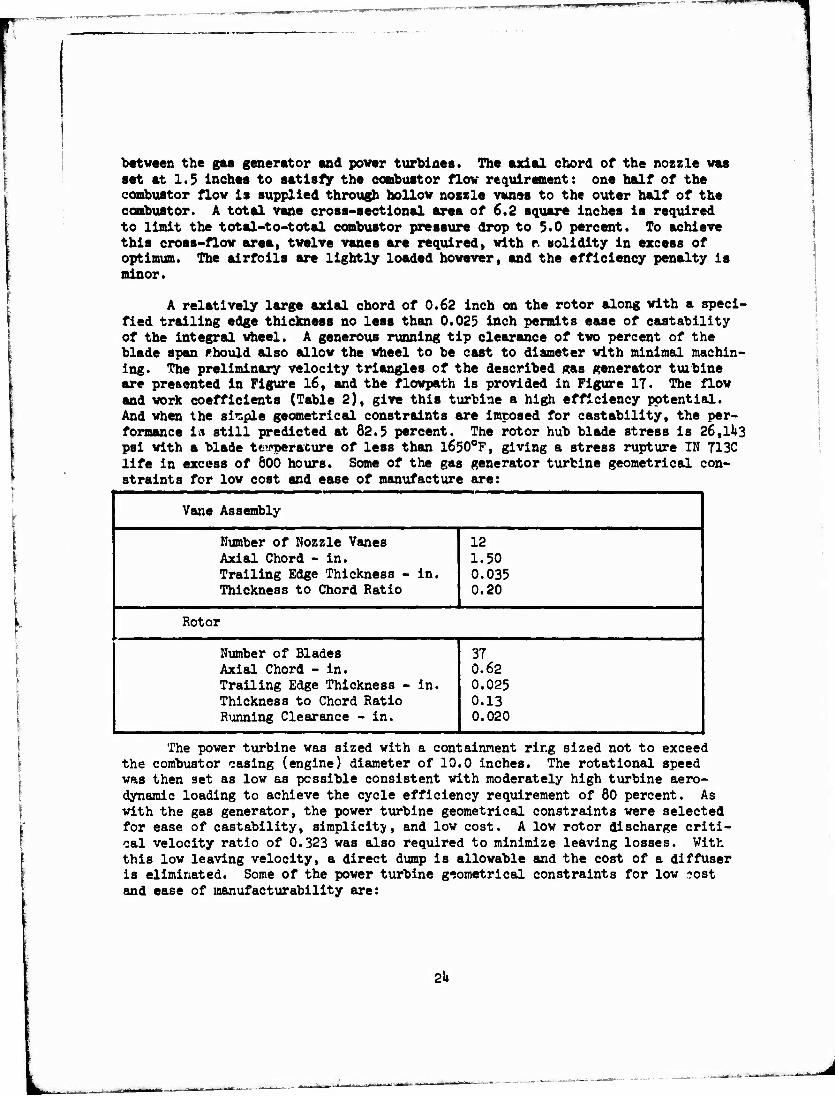
between the gas generator and power turbines. The axial chord of the nozzle was set at 1.5 Inches to satisfy the combustor flow requirement: one half of the combustor flow is supplied through hollow nozzle vanes to the outer half of the combustor. A total vane cross-sectional area of 6.2 square inches is required to limit the total-to-total combustor pressure drop to 5.0 percent. To achieve this cross-flow area, twelve vanes are required, with r. solidity in excess of optimum. The airfoils are lightly loaded however, and the efficiency penalty is minor.
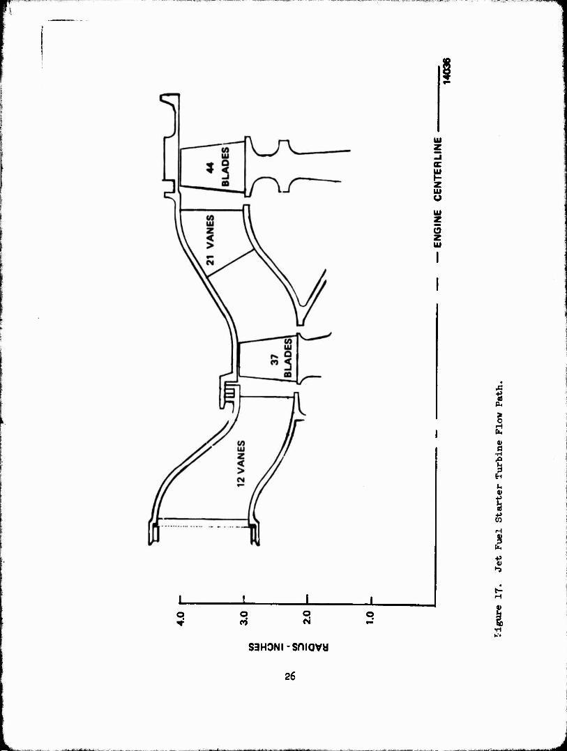
A relatively large axial chord of 0.62 inch on the rotor along with a speci- fied trailing edge thickness no less than 0.025 inch permits ease of castability of the integral wheel. A generous running tip clearance of two percent of the blade span fhould also allow the wheel to be cast to diameter with minimal machin- ing. The preliminary velocity triangles of the described gas generator turbine are presented in Figure 16, and the flowpath is provided in Figure 17. The flow and work coefficients (Table 2), give this turbine a high efficiency potential. And when the simple geometrical constraints are imposed for castability, the per- formance 1« still predicted at 82.5 percent. The rotor hub blade stress is 26,11*3 psi with a blade tejeperature of less than l650°F, giving a stress rupture IN 713C life in excess of 600 hours. Some of the gas generator turbine geometrical con- straints for low cost and ease of manufacture are:
Vane Assembly
Number of Nozzle Vanes Axial Chord - in. Trailing Edge Thickness - in. Thickness to Chord Ratio
12 1.50 0.035 0.20
Rotor
Number of Blades Axial Chord - in. Trailing Edge Thickness - in. Thickness to Chord Ratio Running Clearance - in.
37 0.62 0.025 0.13 I 0.020
The power turbine was sized with a containment ring sized not to exceed the combustor casing (engine) diameter of 10.0 inches. The rotational speed was then set as low as possible consistent with moderately high turbine aero- dynamic loading to achieve the cycle efficiency requirement of 80 percent. As with the gas generator, the power turbine geometrical constraints were selected for ease of castability, simplicity, and low cost. A low rotor discharge criti- cal velocity ratio of 0.323 was also required to minimize leaving losses. With this low leaving velocity, a direct dump is allowable and the cost of a diffuser is eliminated. Some of the power turbine geometrical constraints for low ?ost and ease of manufacturability are:
2k
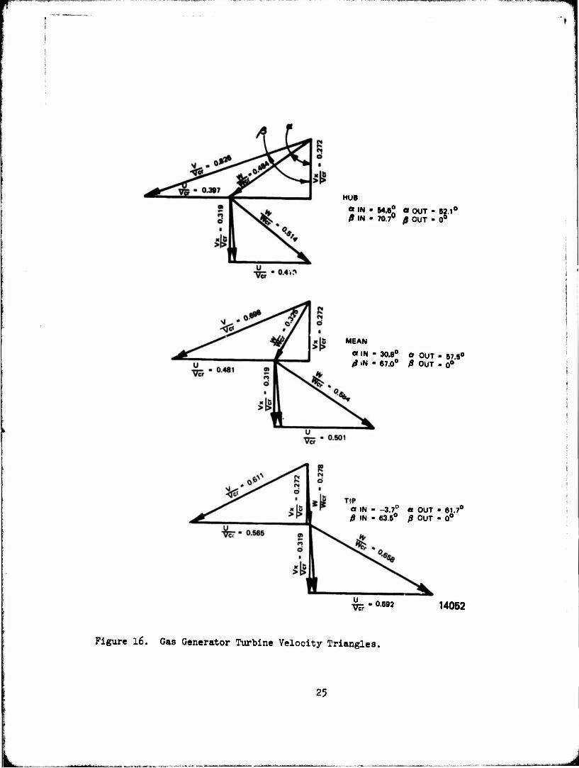
HUB
«IN - 84.6* a OUT - 62.1° 0 IN - 70.7° fi OUT - 0°
MEAN
a IN - 30.8° or OUT - 67 5° ß iN - 67.0° ß OUT . o°
a IN - -3.7° « OUT • 61.7° ß IN • 63.5° 0 OUT - 0°
w, •08M 14052
Figure l6. Gas Generator Turbine Velocity Triangles.
25
UJ
IS z UJ u UJ
z UJ
* fa > 0
ß
1 EH
4)
I fa
•-3
o o
saHONi-sniavw
26
J
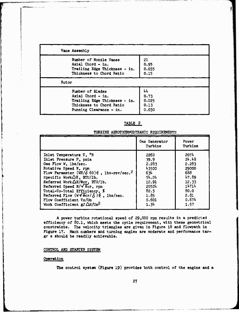
Vane Assembly
Number of Nozzle Vanes Axial Chord - in. Trailing Edge Thickness - in. Thickness to Chord Ratio
21
0.95 0.035 0.15
Rotor
Number of Blades Axial Chord - in. Trailing Edge Thickness - in. Thickness to Chord Ratio Running Clearance - in.
kk 0.73 0.025 0.13 0.030
TABLE 2
TURBINE AER0THERM0DYNAMIC REQUIREMENTS
Gas Generator Power Turbine Turbine
Inlet Temperature T, °R 2260 2071* Inlet Pressure P, psia 39.9 24.1*8 Gas Flow W, lbs/sec. 2.263 2.283 Rotative Speed N, rpm 1*3500 29000 Flow Parameter (WN/tf 60)6 , lbs-rev/sec.2 63U 688 Specific WorkAH, BTU/lb. 5**. 2** 1*7.89 Referred WorkAH/6cr, BTU/lb. 12.91 12.33 Referred Speed N/V9cr, rpm 2052U 1*»71« Total-To-Total Efficiency, % 82.5 80.0 Referred Flow (wV9cr/c5)€ , lbs/sec. 1.85 2.81 Flow Coefficient Vx/Um 0.601 O.67I* Work Coefficient gJ&H/Um2 1.3k 1.57
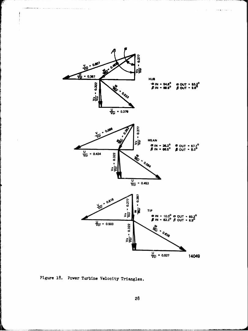
A power turbine rotational speed of 29,000 rpm results in a predicted efficiency of 80.1, which meets the cycle requirement, with these geometrical constraints. The velocity triangles are given in Figure 18 and flowpath in Figure 17. Mach numbers and turning angles are moderate and performance tar- ge' s should be readily achievable.
CONTROL AND STARTER SYSTEM
Operation
The control system (Figure 19) provides both control of the engine and a
27
teS^^*. |r",**TO • 0.367 >
if **4
^
HUB «IN - BM0 « OUT - 83.3° /I IN • 88.9° £ OUT - 9.6°
- 0.378
MEAN
«IN - 36.3° « OUT • 87.1° 0\H • 66.5° fi OUT - 8.0°
«IN - 10.0° a OUT • 60.3° 0 IN - 63.3° 0 OUT - 6.9°
Wr - 0.627 14049
Figure 18. Power Turbine Velocity Triangles.
28
... ■ ■■■■- —■ ■-*—iB^MiHi
h
ft
0
1° OCUJ
si* -I1 WO,
U.UI .
32
-%-^h
o z
§91
281
Vvff H-
o
i (0
I 81
0\ H
Pt,
29
■S^!?^™^™!^«^
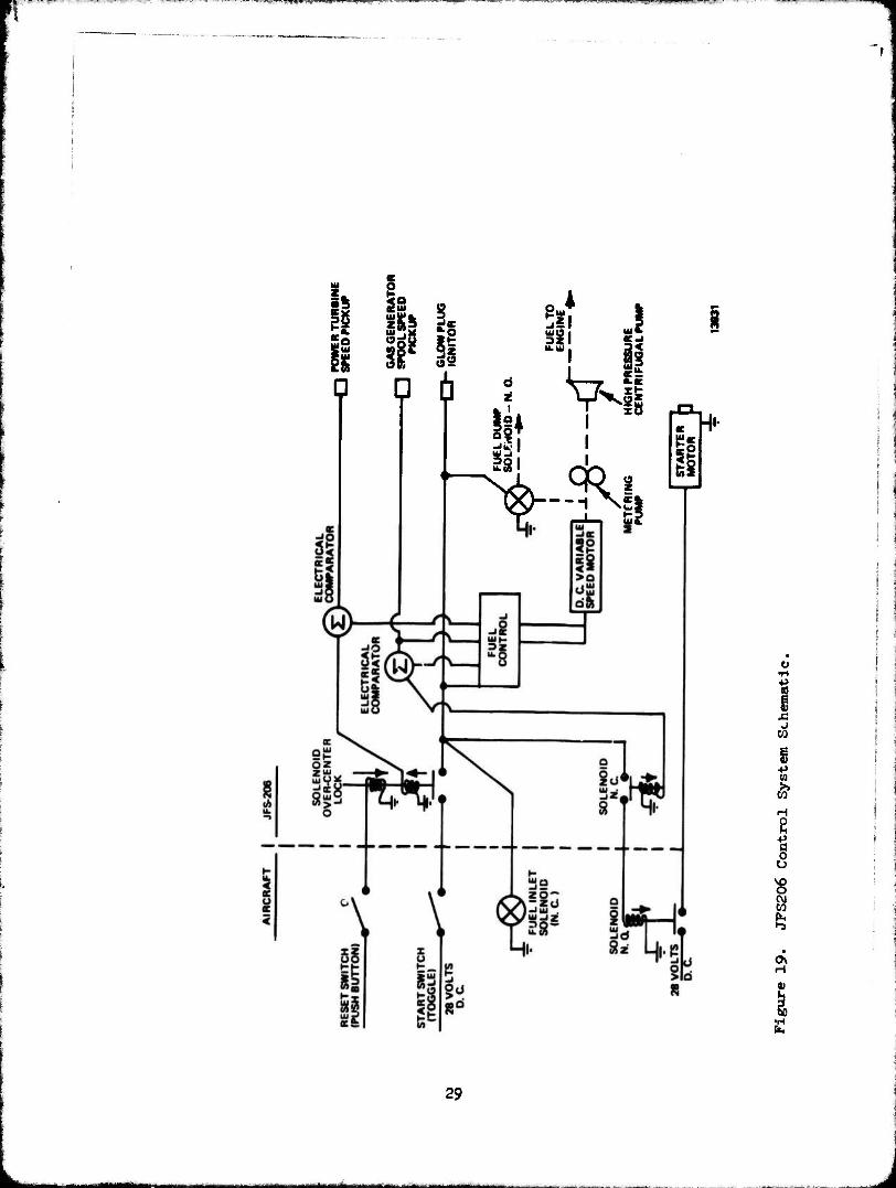
logical sequencing of events to assure proper performance of the overall system. The following narrative describes the basic cycling of the system from startup to shutdown. (Refer to Figure 19)
Startup
A. The reset button is pushed to eliminate the effect from the previous shutdown. The over-center solenoid is energized to the on position.
B. Moving the start switch to the On position initiates a series of events.
1. The fuel inlet solenoid is powered open.
2. The fuel dump solenoid is powered closed.
3. The fuel control is turned on.
h. The glow plug igniter is turned on.
5. The electrical starter motor is provided with a low resistance current path on a separate line by means of two solenoid switches. The first low current switch is normally closed and in this posi- tion closes the second high current switch which is normally open. When the two switches are closed, the starter motor cranks the JFS206 engine to 60 percent speed on the gas generator spool.
6. When the gas generator spool attains 6o percent, a signal from a speed pickup is compared to a predetermined value from the fuel control. The low-current solenoid to the starter motor opens which in turn opens the high-e;irrent solenoid switch. This shuts off the starter motor, thus preventing excessive running of it after the JFS206 has attained self-sustaining speed.
Acceleration
A. During this portion of the cycle, the gas generator accelerates from 6o percent to 100 percent speed and is held at this speed by the fuel control system. This is accomplished by a closed-loop speed sensing system in which gas generator spool speed is sensed and compared to a predetermined value. This comparision is then translated into a drive speed signal and applied to the variable speed D.C. motor. This motor drives a constant displacement pump that provides metering of the fuel to the engine as a function of speed.
B. As the gas generator increases in speed, the power turbine increases in speed and provides the direct cranking power to the driven engine.
30
L_
At a predetermined power turbine speed, a speed signal comparator transmits a shutdown signal to the over-center solenoid switch. Opening of the switch contacts interrupts the electrical power supply to the entire system.
Shutdown
A. Engine shutdown is triggered by the power turbine speed comparator signal. This signal indicates that the driven engine has attained sufficient speed to be self-sustaining. When this signal interrupts the main electrical power supply, a number of events are initiated:
1. The glow plug igniter is turned off.
2. The fuel control is turned off.
3. The fuel dump solenoid is opened.
k. The fuel inlet solenoid is closed.
5. The over-center solenoid is powered open and cannot be closed until the reset button is pushed to initiate a start.
B. The JFS206 then decelerates to a stop and is inactive until the start sequence is repeated.
FUEL CONTROL FUNCTIONAL DESCRIPTION
The fuel control system is divided into two basic subdivisions of elec- tronics and hydraulics. A brief description of the major components and/or divisions follows.
ELECTRONICS
The fuel control electronics portion is basically an isochronous governor which uses speed signals from both the high- and low-pressure spools as well as a speed signal from the constant displacement fuel pump to generate a control signal for the variable speed D.C. motor. The gas generator signal is used to reduce the predetermined 100 percent speed demand signal until constant speed is achieved. The control uses a sequential series of select gates in a speed select network to provide the final D.C. motor drive signal. The inputs into this net- work include:
A. Maximum Wf (preset)
B. Starting Ramp Wf Rate (Generated Internally)
31
1
C. Topping Governor Wf (from NHP)
D. Minimum Vf (Preset)
E. Fuel Shutoff (from NLP)
In addition, the control provides speed signal values for both speed comparators to shut off the electrical starting motor at 60 percent gas generator speed and the entire system when the power turbine achieves 100 percent speed.
HYDRAULICS
The hydraulics section consists of a positive displacement pump, a vari- able speed D.C. motor, a constant pressure rise regulator, and a vapor core high pressure pump. The D.C. motor is driven and controlled by the output from the electronics and is independent of gss generator spool speed. The fuel from the pump passes through an orifice controlled by the constant pressure rise regulator thereby providing a very reproducible and predictable measure of fuel in proportion to pump speed. The high pressure vapor core pump is driven by the gas generator and provides sufficient pressure to overcome CDP plus fuel orifice pressure drops in the combustor.
32
J
SECTION III
DESIGN ASSURANCE
APPROACH
During the study phase of the low-cost Jet fuel starter program, Teledyne CAE conducted an on-going assessment of its design-assurance (or "utility") attributes.
The study approach considered reliability, maintainability and system safety as related objectives. Their worth or "utility" had to be evaluated in concert with the low-cost, adequate performance and user convenience objectives of the program. We, therefore, selected the Failure Mode Effect Analysis (or FMEA) technique, because it can be expanded to answer such questions as:
1. Will the starter provide adequate reliability for the 2000 starts between overhaul "mission"?
2. Should maintenance aids, such as failure indicators, be included, and would their added cost be Justified for a prospectively high-reliability device?
3. Do the modes of failure present hazards that are unacceptable by virtue of probability or consequence?
k. Would reliability enhancing design features improve the over- all cost of ownership?
The results of the FMEA are discussed in the following subsection. In summary, they confirm that the basic approach will provide acceptable utility. However, it was also found that acceptably accurate forecasts of user life cycle costs require the design definitions and cost data that will be more readily acquired in the demonstrator engine development program.
RELIABILITY ANALYSIS
A preliminary reliability analysis of the JFS206 has been accomplished. The calculated result is based on conventional methods for assessing the re- liability of individual mechanical, electrical and electronic components. Also, the estimated failure rates for electronic parts are based on the use of "good commercial" or industrial-quality parts, with no recourse to Mil-Spec type screening or reliability conditioning (burning-in) at the part le/el. As the JFS design becomes progressively defined, the value of a control-assembly burn- in will be evaluated.
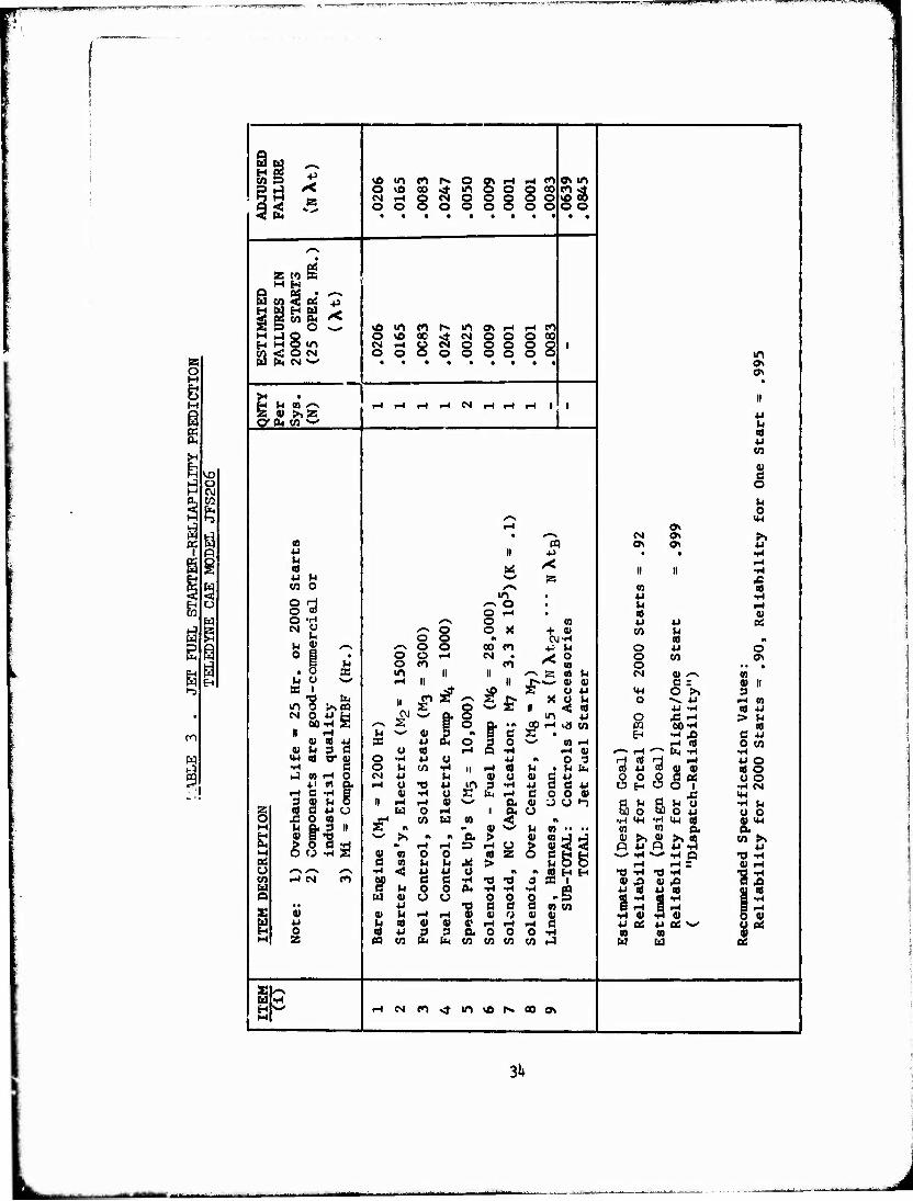
Also, because of the cyclic duty cycle, the mean-time between failure data has been converted to a failure per overhaul cycle basis. The results of the analysis are shown in Table 3, together with recommended design goal values and
33
VO O CM to fa >-}
p
w B i
00
W
3
si * Sri *
VO U1 en r-» O c» i-l r-l «n o\ m O VO 00
* m o o O 00 cn •*
VO CO CM iH § O o § o o O o o o o o o o o
< fa
<""N
z w S M H
Q at • <— W CO <5j Mi p
« S w s ^ So o «— vO to cn r» m O» I-H r-4 cn HJO o vO « •tf CM o o O 00 H H o m CM i-H o CM o o o o o 1 W <ON O o o o o o o o o m W fe CM w • • • • • • • • • Ov
• II
H w co <~. rH p-l 1-* r-l CM rH r-l r-4 1 1 Z 0) >>z i 4J cyfcio^ 1 U
«0 4J CO
| o M 0 -*-\ HH
r-l Ov • *-"■*» CM ON rS (13 m OV Ov 4J 4J II 4J • • •rl u Cd us r<
11 11 t-t iH
*J M «»» z rC CO O
m CO 4J
(5 •H
o to /-\ o • u rH o rH ■ ca 4)
O «H /—» o CO 4J 4J 0Ü CM CJ /-N O o X + 01 CO r4 M o o A CVI-rl ca #1
H SJ '""* /~v o o oo cn ■P u O 4J o o a • O o r-l CM • ^* (0
O CO Ov « a O cn cn O • • ■ • O x m II II *~> z «o h CN 41 '-v CO h «J "-' i-< ii II !>•—- 01 01 e = 4) II
H $ if o if £ S CJ 4J
X CJ »4 ii «ü ca
«f4 O >v O ->, 4J
4J -H
3 rH CO Cd 4-1
CM O 4J H MUH s
n i-4
N-' Q, o tn 4J O JS r-l > rl
U m j3 o 1 c JIH^ M PQ 60-rl
EH -rl rO - * d 4-1 <U efl 4J S3 <J P-l o ä 0 ^^ CO r-l rH Id 0 CO
<U U 3 C o eg r-4 •H r-4 01 r-» r-l »^» fa iH •ri tJ « CD O •H 4J o 4J O 3 HUH r-l
a) u ™ CD 41 4-1 O •H c o H CO •H 11 I-I ca h • U fa cd O
hl «H O CM 4J U 01 o 41 S ti 4J CJ C 4J cS^cSc!^ CJ O 4-i « ft t-t u •o 4-1 & 3 •H iH CM
3 <u u 6 0) •H O s fa r-4 BOOH J3 IM
II r-l p-l ai N-' ft 4» -J CJ ^ bD o S) O 4J
•rl M g a) C 4J u w O i-i | ft O CJ 0 o r 2 2 jH CO w CO < A •H M-l <H CM Cd 4) <4H H h Q.3 II
4> B "2 s 91 — « N-/ p CO *• •• M W ft ft
B ■w» _>> n rH r-l £ >
r-4 Ü 6 ess Q«J Q Url
CO rS U
S (0 ca
o o rl rtt >
z v-'i4*>^ Q rH i-4 =
•O -rl 41 rH
CJ <—\ ^-\ /-N i-i < w 4-1 CJ m, * «a H H TJ iH <0 -rl "8S CO i-( CM cn 1? a e 1-1 ■a •o o as i 4) U3 41 4 H H 0 o fa •H 1-1 14 A Q -5 4J « 4J ffl 41 4 O w «V u o 0 0 13 Sri
•rl 4) -H 41
1 -S £
•• 4J ■o a S d co co 1 «-< 0) V M •-I i-H 41 V t.i 0> 01 5 41 8 u u cd <u CD «• i-i <-* r-4 d 4J CtS 4J BS -^ CJ Qi 0 CCt 4J 3 3 0. 0 o O -rl CO 01 41 M Z M CO fa fa to co co CO (J u u <2
s *-v w •H H w iH CM cn <* m vO r» 00 o> H
3H
J
specification requirements for follow-on phases of the Jet fuel starter develop- ment. These values are:
1. Reliability for one overhaul cycle (2000 starts). Objective ■ 0.92, Requirement * 0.90
2. Reliability for one start Objective « 0.999, Requirement « 0.995
MAINTAINABILITY
Maintainability factors for the JFS206 will vary as a function of, l)spe- cific aircraft installations; 2) the using activities maintenance doctrine; and 3) the capability of ground equipment.
The aircraft installation will large?.y determine the time to repair or replace a suspect starter and will also establish the feasibility of replacing JFS accessories on aircraft.
The maintenance doctrine will determine the intermediate maintenance level or off-aircraft maintainability. For example, one doctrine could require that any suspect unit be returned to a depot, while another would require tear-down and replacement at i Jet Engine Base Maintenance facility. The appropriate doctrine should be determined by conducting an Optimum Repair Level Analysis (0RLA).
The capability of support equipment will affect the time to diagnose, repair (if necessary) and return a suspect unit to service.
The foregoing consideration requires some assumptions about the maintenance environment of the JFS206 in order to estimate its maintenance index. These are:
a) In most applications, the unit will not be accessible for on-aircraft repair.
b) Off-Aircraft repair will be accomplished at a Jet Engine Base Maintenance Facility.
c) Control and accessory components will be repaired by replacement for an active maintenance time of one hour.
d) Bare engine component repairs will also be accomplished by replace- ment after an engine tear-down inspection, for an active mainte- nance time of two and one-half hours.
The maintenance task times must be weighted with their relative frequency. For that purpose, the reliability analysis indicates that there will be three control and accessory actions for every action affecting the Bare Engine. The overall index is therefore calculated from:
35
Met »(3x1 hour + 1 x 2.5 hours) /U « 1.375 hours.
Where Met ■ Mean Corrective Maintenance time.
HAZARD ANALYSIS
The safety analysis considered all failure modes classically exhibited by small turbo-machinery. The design has incorporated containment rings around critical areas to absorb energy and retain fragments should catastrophic failure of rotating components occur. Low stresses and temperatures inherent in the design have contributed to reducing hazardous failure probabilities. The hazard analysis is part of the integrated FMEA described in tne next subsection.
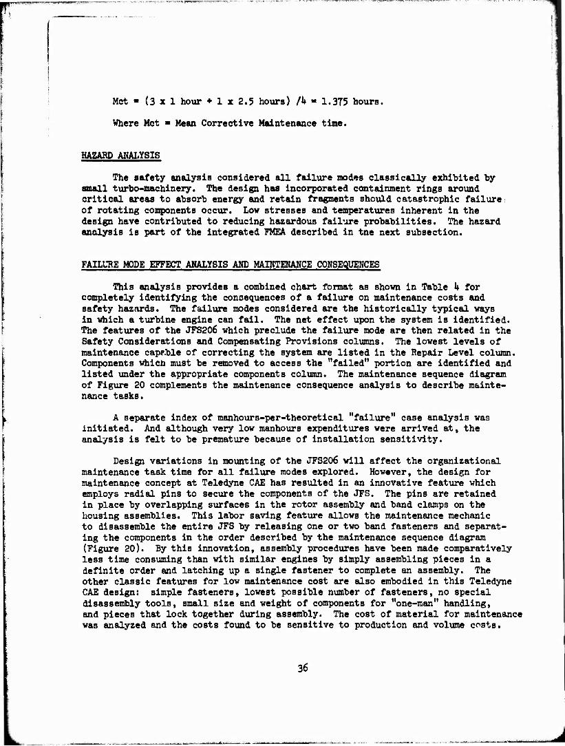
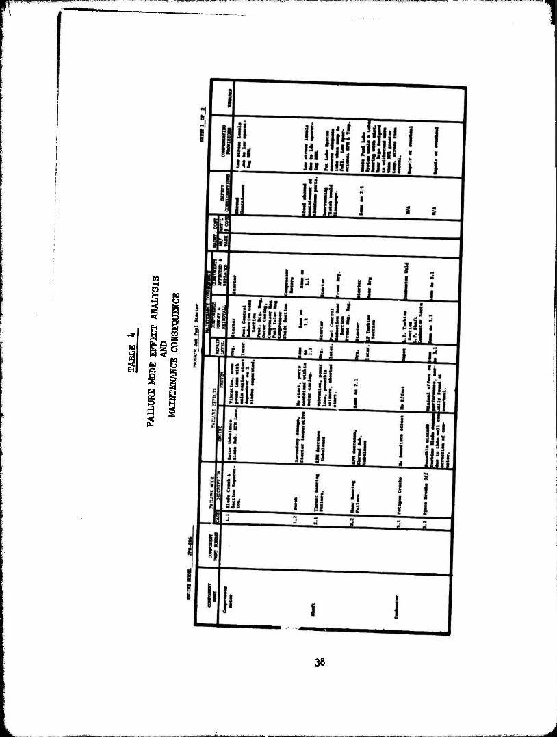
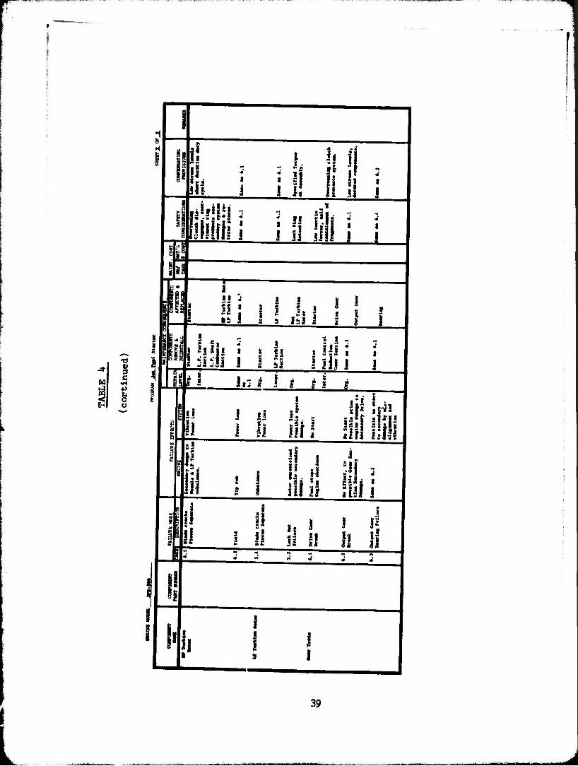
FAILURE MODE EFFECT ANALYSIS AMD MAINTENANCE CONSEQUENCES
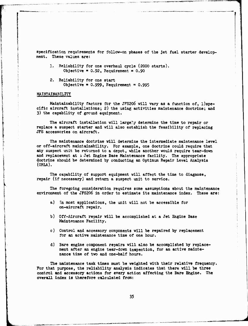
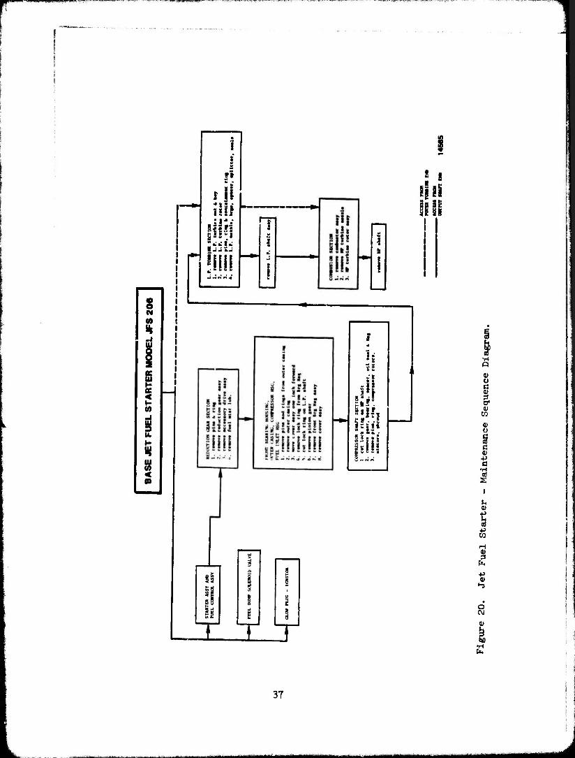
This analysis provides a combined chart format as shown in Table k for completely identifying the consequences of a failure on maintenance costs and safety hazards. The failure modes considered are the historically typical ways in which a turbine engine can fail. The net effect upon the system is identified. The features of the JFS206 which preclude the failure mode are then related in the Safety Considerations and Compensating Provisions columns. The lowest levels of maintenance capp.ble of correcting the system are listed in the Repair Level column. Components whicn must be removed to access the "failed" portion are identified and listed under the appropriate components column. The maintenance sequence diagram of Figure 20 complements the maintenance consequence analysis to describe mainte- nance tasks.
A separate index of manhours-per-theoretical "failure" case analysis was initiated. And although very low manhours expenditures were arrived at, the analysis is felt to be premature because of installation sensitivity.
Design variations in mounting of the JFS206 will affect the organizational maintenance task time for all failure modes explored. However, the design for maintenance concept at Teledyne CAE has resulted in an innovative feature which employs radial pins to secure the components of the JFS. The pins are retained in place by overlapping surfaces in the rotor assembly and band clamps on the housing assemblies. This labor saving feature allows the maintenance mechanic to disassemble the entire JFS by releasing one or two band fasteners and separat- ing the components in the order described by the maintenance sequence diagram (Figure 20). By this innovation, assembly procedures have been made comparatively less time consuming than with similar engines by simply assembling pieces in a definite order and latching up a single fastener to complete an assembly. The other classic features for low maintenance cost are also embodied in this Teledyne CAE design: simple fasteners, lowest possible number of fasteners, no special disassembly tools, small size and weight of components for "one-man" handling, and pieces that lock together during assembly. The cost of material for maintenance was analyzed and the costs found to be sensitive to production and volume costs.
36
^B^^mammm
lü
■
1 i w M
fl »a -
Hi
Stfls S *«1» l J J IJ
!!!!!
s a*
I tv
J
i
i
si! JE • ^ *
Sal! Irs a« O 5 « • S
> Sj a i
is 1 u s
ft <* V)
i (fl c
T T T
I if
Q V a
! ID
CO
<D O
S •H ed S
I
S ■p to
s ■p
hi
o
0)
•H
37
CO H
w a
fi
s w o 5
§ i
38
w 8 c
•H +> o
I t 1! ill
5 fi ! J i d ii y i i'j'fli s
fi ii if if i i 0 ill j M
:if
It J I
I i$ ist I Ü tl . t Hi I
m± Ii
«9
n
I'
Ji: | I I
jj i.
y i i
i L
I ii i M Ji I i i f
ill Uii
I Ii lit.1 ihllitli If i ' • I I oi.IT
* 111 !il|» g I Jills Ail J
'In1 * j! I i? 3J I! H U
L 39
-iu_._i._i i HM 1 i
This analysis is also premature for determining dollar values; this can be accom- plished in a demonstrator phase. The simplicity of the design» and the low cost of parts will definitely affect spares costs and repair material costs in a posi- tive manner. The sparing strategy for the low cost, die cast, axial compressor rotors is a case in point. The low cost of the material is additive to the setup and machining time. The setup and machining time is cost sensitive to the quanti- ty to be run, over which the machining costs are amortized. During the demonstra- tor phase of the program, we can realize the cost impact, derive actual cost values and thereby recommend optimum sparing levels.
1*0
SECTION IV
COST ANALYSIS
APPROACH
The Jet fuel starter has been subjected to a cost analysis based on an established Design-to-Cost procedure. The method selected is based on: (l) identifying the "finite elements" of engine cost, at the part design level; (2) providing the designer with "real time" knowledge of the cost consequence of his design decisions; and (3) providing management visibility of on-going success in achieving cost targets.
Other constraints and considerations addressed in the development of this method are:
1. It must provide uufficient detail to be useful for the appropriate phase of design.
2. The method should be compatible with manual as well as data processing compilation procedures.
3. The approach must provide the manufacturing engineering activity with sufficient information to critique the design intent and contribute to achieving the cost objective.
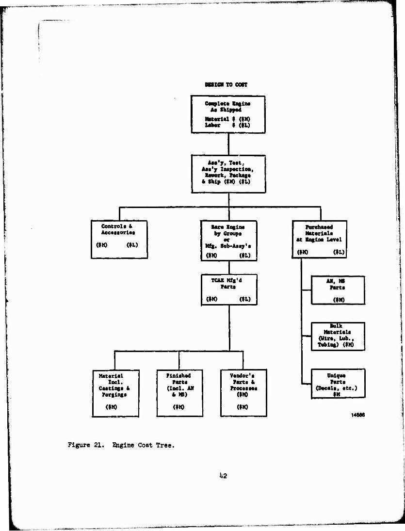
The approach utilizes the cost-tree procedure to allocate initial cost objectives and commitments to engine groups, parts, and controls/accessories. A typical cost-tree for a hypothetical engine is shown on Figure 21.
During the design process, the cost of manufacturing (or acquiring) each part is compiled by finite elements. The elements include the man-hourJ for individual manufacturing operations, the material costs and the support costs (in man-hours and material) of inspection, tool support and certain overhead Operations. Man-hour and material costs are entered as "burdened" values and performance indices and anticipated scrap rates are included for each operation, or summarised for each part.
The finite element work sheet also provides for a progressive identifi- cation of the cumulative value of the part by summing each operation's "added value". This data aids in determinations such as: when to inspect; when to stop advance production (to minimize inventory cost); and (in actual production) the optimum decision for Materiel Review Board and scrap actions.
These medhods facilitate evaluating the cost consequence of changes in design and/or manufacturing operations. It also allows for estimating or speci- fying cost objectives as a function of production quantities and delivery rates. Burdened rates are used for material and labor but the burden (overhead and material handling costs) may vary as a function of the production quantity being estimated. However, all values are still in terms of cost and not price (i.e.,
1*1
net leu TO con
-JL-.UPJL-
Controls 4 Accessories
(IK) WD
Coaplat« lagtM Aa Shipped
MKerlal $ ($10 Ukor | (»D
Aea'y, Tut, Aaa'y Inspection,
tenor*., Package * Ship (|M) (ID
Bar« logins by Groups
or Mfg. Sub-Assy's
(IM) ($L)
TCAE Mfg'd Pares
WM) (ID
Matarlal Incl.
Castings & Forging«
Flnlahad Parte
(Incl. AM * W)
Vandor'a Parts 4 Proeasaaa
(IM)
(|M) (IM) (IM)
Purchaasd Matarlala
at Ingina Laval
(IM) (ID
ETC Matarlala
(Wre, Lub., Tubing) ($M)
Onlque Parta
(Dacals, ate.) !S
14666
Figure 21. fcigine Cost Tree.
1*2
they do not include G & A or Fee).
The cost of producing the specific parts of an engine are periodically compiled (by manual or data processing methods) into cost summaries for engine groups and for the total engine. This cost summary is then evaluated with res- pect to the initial cost objectives and commitments and also serves as an iterative cost model for the engine model of interest.
All values have been purposely retained in terms of cost to permit the designer to recognize the impact of his decisions towards achieving the cost targets. It is simply a matter of including G & A and Fee for the total engine cost to present the total selling price.
COST
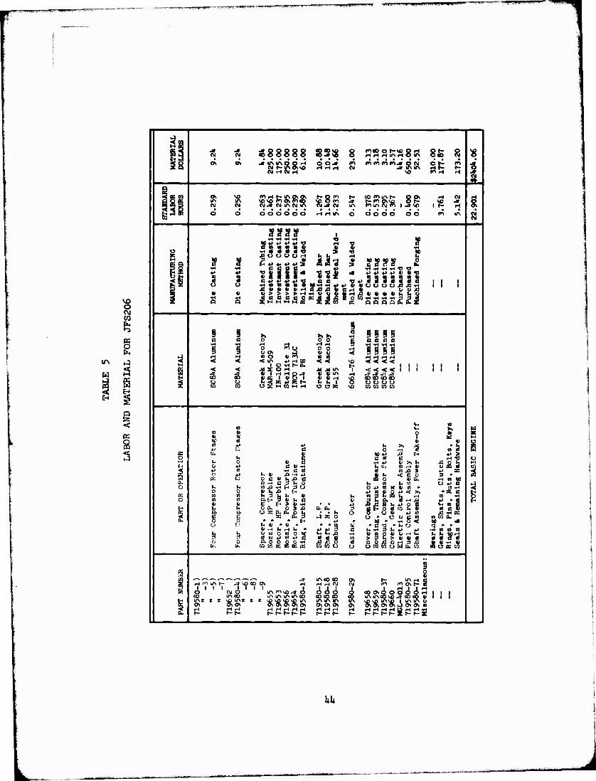
To determine the cost to the customer of the JFS206 jet fuel starter, an abbreviated version of the detailed analysis described in the previous section was applied to all components of the engine. The results of the analysis are summa- rized for the major components of the JFS206 in Table 5. Experience has shown that preliminary cost of the components can be determined by a simplified approach which applies factors to both the standard labor hours and material dollars to arrive at total cost. This procedure uses the detail costing sheets filled out sufficiently to provide standard labor hours and material dollars for each component. These results are shown in standard labor hours and material dollars since each is treated differently in arriving at the selling price. The standard labor hours require additional labor hours for assembly, test and support functions and can be applied as a factor of 3.35 times the standard labor hours. This factor to esti- mate the supporting labor hours required is based on recent history of production engines, as these hours are representative to the effort required to support the direct machining and fabrication operations in the manufacturing of a gas turbine engine. The conversion of these labor hours to a selling price is accomplished by adding to the labor rate all burdens such as overhead, G&A, and profit to arrive at a st «.ling price of $23.59 per labor hour. Tne matcial dollars for purchased parts ail material is handled at a different rate. The total burden for material includes material overhead, G&A, and profit and can be applied as a factor of 1.1*6 times th! material dollars.
Us: ug the factors described and the data summarized in Table 5» the JFS206 price is a? follows:
Labor Hours - 22.9 x 3.35 x $23.59 Material Dollars - $2l»0U x 1.1*6 Basic Engine Tooling and R&D Amoritzed over 2500 Units.
Total Estimated Price
$1810 $3510 $5320 $2021
$73fcl
The budgetary unit production price includes Production Tooling and R&D amortized over 2500 units as established for this study and is based on FY19T1* economics.
•3
-■- - sfcaa
-....I_L.IL.i |uii(Üurn
3
O P-,
<
äs co 8 8 8 8 8 33$ 8 nooNwoH of- o
rlHHUSHOin OCO (Q « • • • is o> at jinmooH CM I-IAOSSO (IIHNrl
O O J» H iH H
CO (SI JKSIIS H t- 1-
\0 fn rt H i n
SEN UN CM
sp so m Osroco t- o en toon cv -a CM IA
copiiAt- got H cti ►- en otso o t- so J i^iASjroi^»\o it- H 1 • • • • ••• •• • •
B" O o o o o o o o H H IA o OOOO OO m IA si SUV* 1 ■rt -H -t-t -H n If
■H M o lijiil •3
«1
E .o o o o o H
IÜ4 H E
K a s If 6 «J ♦. 4» ♦» S jf ?§?? £ ♦> n s
•H *> s o A 1 « • IIH ?«< •
£.5,5.5,5 «§**$,£
»1 ■rl -H »H TI « 4 *»♦>♦>♦' «I*«
•«■►'«'38883c II i puiuoouuÄjS'rt ii i 3 i-l II u ü ß
■ II •H Q
II •H a cc o Q o a t (£ x
§ I s X X 1 c SISi a a 0 0 0 § ß C C ß
•H •H o nu CJ OS (J no * ro < IT« *) rH *
l-> M <Hi4ri<H § SI 0 0 3 3 9 91
3 3 3 a n < < SO 3335 M J. O -H »- S ft iii II i i < < JC i O H M M IA < < < < i i i ii i
CD 3 U 1 rlHOJ Ji a, 1 «1 G 1
1) tl IA II II M *
-* J -t -3 coco coco s tt o MK»""" U U 1 OOOO
to OSMOMrt o o a SO co en co co
H II
o ii
Sf ? 1 II II
H
s O r-f 0 CD « s s 0". 01 HI +J -a fH <-> > o h
C 1» •*
C » E H t) o 1. o
0 +-
■rt*i U>.r. •cob IV-4
♦. 5! •Had d m & i ti X •rf o «-> t* II _o •* *> II «- < B 0 3 •
no B a. -H « M w o: c; 0 C 11 tj J-l c a •-. ö 3 u o o. h n L, n o +» 0 1 o >* u a ft -H H a u o -n n x u m • S-H 0 0 II ij ä t-
I» 3 M l. II UH 3 II i. a
I><IO«><>, *se U r -IS L r-1 n >H 3 fc a, 9 ri« <J » «J
a P o a eo ». ii « c u S ot> »J to a -H tc u » o a c n ntOCL
K n n h C as n II ItH
u ti e Miii 0 A. 0 5 *
• • *J b u a. o. 9
g p. E
a. e
ui^n J X 0 O
0. 0 0 • • • fr-l *i Ml » -rt 0 < to •* o O l* 41 * II P
S S B
Hi • B "O • 1, o I3P» UH h H t< * c u «« 3 u ±> *> —* so a w
S3 3 U M O N 0 tf
Ö. 0 0 ,0 0 •* laziclSKiii
u t lOlltlHti L,Lc0rH >3<4>iiiia m « cT «
o 0 u- B1B1U
0 O
OOÄOCJ3J5 Sll-rtll o s c/J o w fc. co fSuceco
fS i i
Us H^mi- .» so CO OS H «H rH CSI OS CM
0- IA M C ro ci Os t- 0
g 1 1 1 o csi o
1 1 «sn\Od o
CO CD CO o cOOsOOOOOiH 1 1 1
CO mco IA IA IA IAC0 CO IA IA CO SO-» CO CO «III
I U"st E S OS
SO IAS E OsOs
C \D SO SO SO IA OS OS OS OS Os o\ ON OS
IA Os
SO SO IAS^ | IA IA CJ Os OS Os OS »-) OsOs 10
-1 r-l r-i f-t rl H H i- I- t» r- i-
H i-l r-l t-
HHrlHBrtHjH
J.1»
SECTION V
ALTERNATE DESIGNS
JFS2Q6-A1 J^OIHE DESIGN
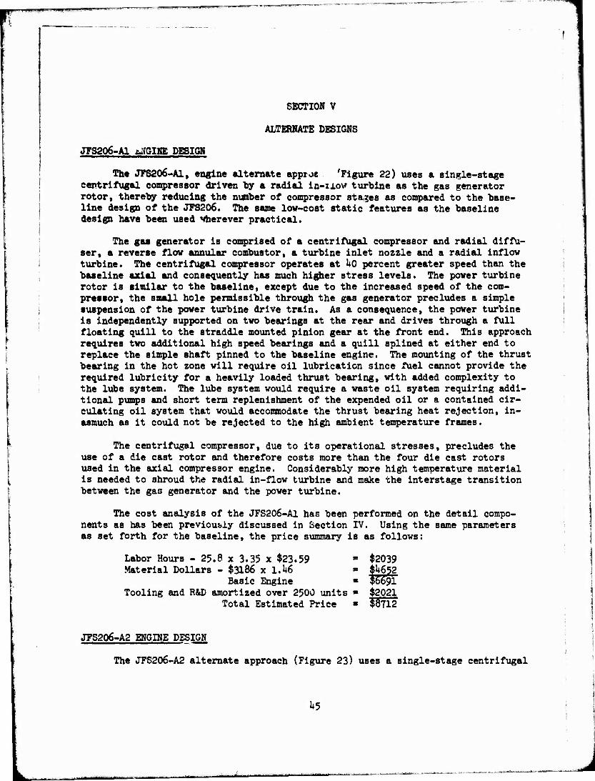
The JFS206-A1, engine alternate appro« 'Figure 22) uses a single-stage centrifugal compressor driven by a radial in-ixow turbine as the gas generator rotor, thereby reducing the number of compressor stages as compared to the base- line design of the JFS206. The same low-cost static features as the baseline design have been used wherever practical.
The gas generator is comprised of a centrifugal compressor and radial diffu- ser, a reverse flow annular combustor, a turbine inlet nozzle and a radial inflow turbine. The centrifugal compressor operates at Uo percent greater speed than the baseline axial and consequently has much higher stress levels. The power turbine rotor is similar to the baseline, except due to the increased speed of the com- pressor, the small hole permissible through the gas generator precludes a simple suspension of the power turbine drive train. As a consequence, the power turbine is independently supported on two bearings at the rear and drives through a full floating quill to the straddle mounted pinion gear at the front end. This approach requires two additional high speed bearings and a quill splined at either end to replace the simple shaft pinned to the baseline engine. The mounting of the thrust bearing in the hot zone will require oil lubrication since fuel cannot provide the required lubricity for a heavily loaded thrust bearing, with added complexity to the lube system. The lube system would require a waste oil system requiring addi- tional pumps and short term replenishment of the expended oil or a contained cir- culating oil system that would accommodate the thrust bearing heat rejection, in- asmuch as it could not be rejected to the high ambient temperature frames.
The centrifugal compressor, due to its operational stresses, precludes the use of a die cast rotor and therefore costs more than the four die cast rotors used in the axial compressor engine. Considerably more high temperature material is needed to shroud the radial in-flow turbine and make the interstage transition between the gas generator and the power turbine.
The cost analysis of the JFS206-A1 has been performed on the detail compo- nents as has been previously discussed in Section IV. Using the same parameters as set forth for the baseline, the price summary is as follows:
Labor Hours - 25.8 x 3.35 x $23.59 ■ $2039 Material Dollars - $3186 x 1.U6 = $U652
Basic Engine = $6691 Tooling and R&D amortized over 2500 units = $2021
Total Estimated Price = $8712
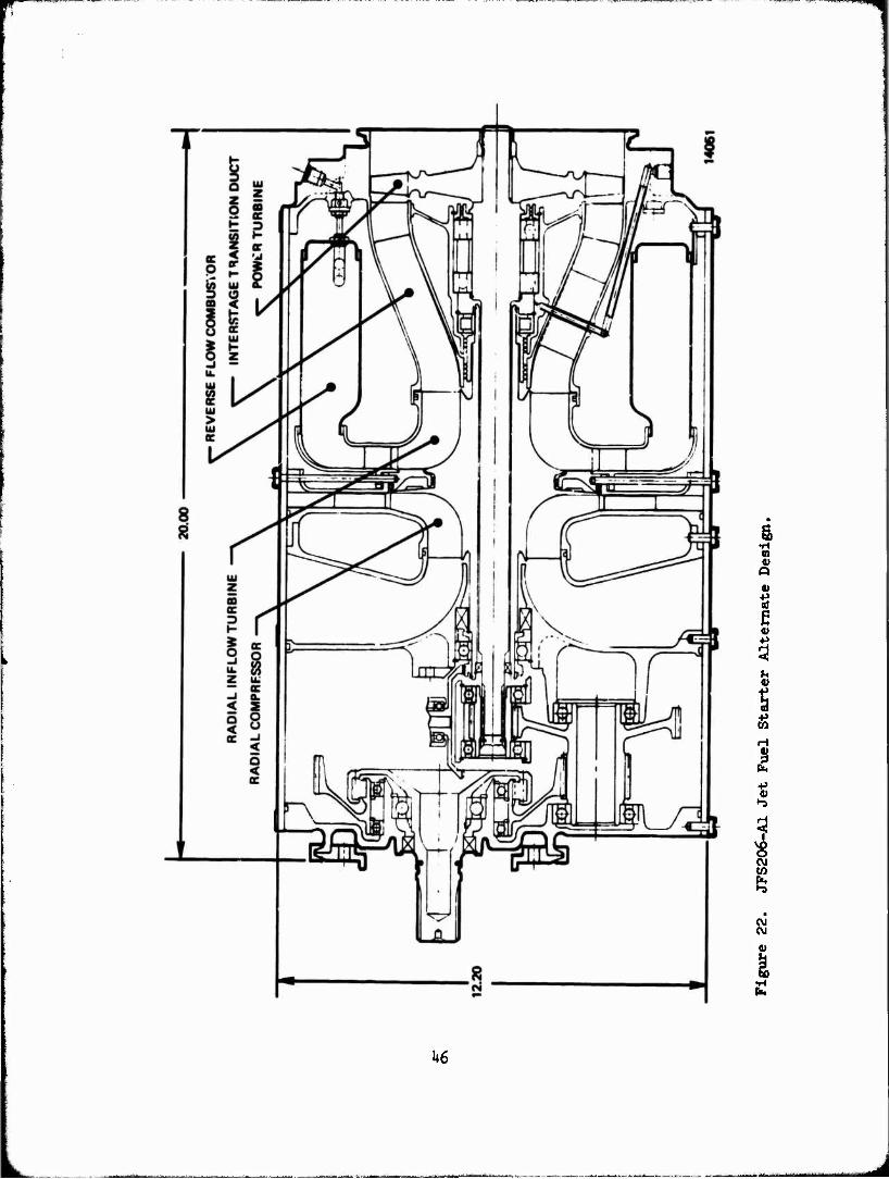
JFS206-A2 ENGINE DESIGN
The JFS206-A2 alternate approach (Figure 23) uses a single-stage centrifugal
1»5
g, V Q
0)
t ß
3 h V
t H
I •P O
"-S
IS OJ w ft
CM
i
h6
03
Q
V
I b S
4
in
(N
ft
on eg
I lb
I i
U7
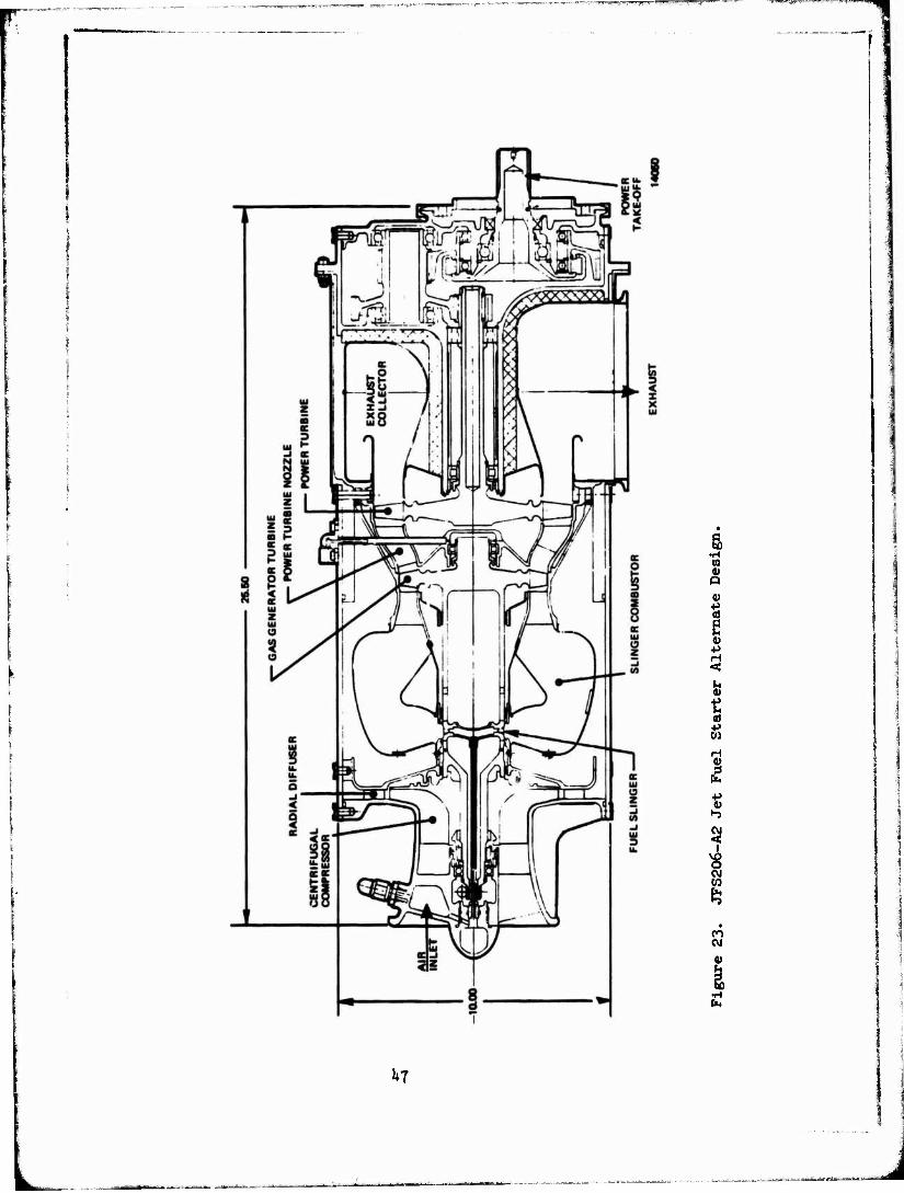
1 compressor driven by an axial turbine with rear power take-off and incorporates a slinger combustor to eliminate the problems associated with multiple injection in an annular combustor. The engine design uses a gas generator which is essen- tially th-3 qualified (MQT) Teledyne CAE T-65 turboshaft engine, except for the removal of the supercharging axial compressor stage and replacing of the two-stage axial turbine with a single stage because of reduced work requirements. All de- tail design parts are modified to reflect the requirements for the Jet Fuel Starter (i.e., 2,000 starts at h5 seconds per start.between overhauls). The design uses the low cost static structur* features of the baseline design wherever practical.
The engine gas generator uses a single-stage centrifugal compressor and radial diffuser, a slinger combustor and an axial flow gas generator turbine. An axial-flow, free power turbine drives through a reduction gear and an overrunning clutch similar to the JFS206, except in this case the power takeoff is at the hot end of the engine and a concentric through-shaft is not used.
Air enters the centrifugal compressor, passes through a radial diffuser, then into an annular slinger combustor where fuel is added and combustion takes place. The hot gases pass successively through the gas generator turbine and power turbine, then enter t'.e exhaust collector and exit at a right angle to the engine.
The fuel admission is through the center of the Mgh speed rotating shaft and discharged through a row of holes in the shaft that makes up the fuel slinger. The injection velocity is derived from the tangential speed of the shaft and is thereby relatively insensitive to variations in fuel supply pressure.
The samp high-f-.p^ed compressor design as discussed for JFS206-A1 is used with the attendant fabrication cost due to the higher stress levels than the baseline design. An obvious added complexity with the non-through-shaft design is the com- plex, high temperature exhaust collector that must be provided to deflect the hot exhaust gases from the reduction gear. Additional complexities arise from bridging the exhaust collector with a cool structure and providing a large single outlet for the exhaust.
The cost analysis of the JFS206-A2 has been performed on the detail components as has been previously discussed in Section IV. Using the same parameters as set forth for the baseline, the price summary is as follows:
Labor Hours - 35. ^ x 3.35 x $23.59 a $2798 Material Dollars - $3503 x 1.1*6 = $51lh
Basic Engine = $7912 Tooling and R&D amortized over 2500 units ■ $2022
Total Estimated Price * $9933
COST AND PERFORMANCE COMPARISON
The alternate design approaches discussed under the previous two items have been presented to provide a comparison to the baseline design. The more conven-
1*8
in 1 in* J
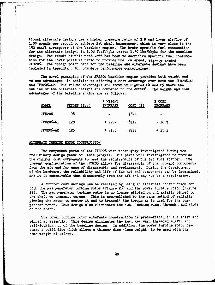
tional alternate designs use a higher pressure ratio of 3.9 and lover airflow of 1.95 pounds per second to achieve 1^8 shaft horsepower, which is very close to the 150 shaft horsepower of the baseline engine. The brake specific fuel consumption for the alternate designs is 1.08 lbs/bhphr versus 1.30 lbs/bhphr for the oaseline design. The result of this trade-off has been to sacrifice specific fuel consump- tion for the lower pressure ratio to provide the low speed, lightly loaded JFS206. The design point data for the baseline and alternate designs have been included in Appendix C for complete performance comparisions.
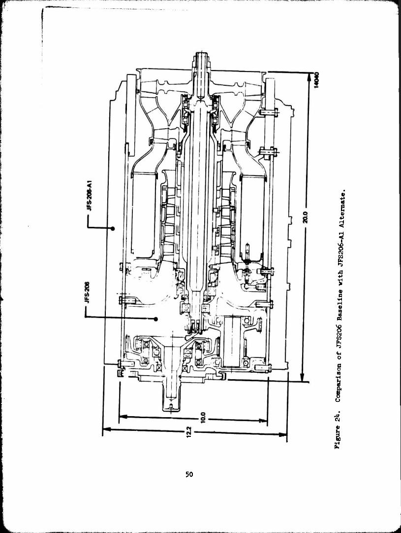
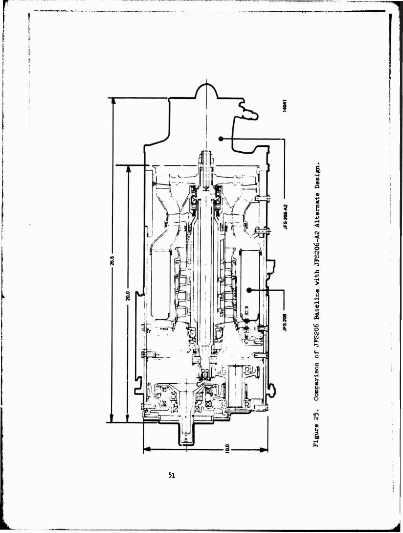
The novel packaging of the JFS206 baseline engine provides both weight and volume advantages in addition to offering a cost advantage over both the JFS206-A1 and JFS206-A2. The volume advantages are shown in Figures 2k and 25 where the outline of the alternate designs are compared to the JFS206. The weight and cost advantages of the baseline engine are as follows:
% WEIGHT % COST MODEL WEIGHT (lbs) INCREASE COST (*) INCREASE
JFS206 98 - 73^1 -
JFS206-A1 120 + 22.U 8712 + 16.7
JFS206-A2 125 + 27.5 9933 + 35.3
ALTERNATE TURBINE ROTOR CONSTRUCT: ION
The component parts of the JFS206 were thoroughly investigated during the preliminary design phase of this program. The parts were investigated to provide the minimum cost components to meet the requirements of the Jet fuel starter. The present configuration of the JFS206 allows for disassembly of the hot-end components from the aft end for ease of disassembly and replacement. During the development of the hardware, the reliability and life of the hot end components can be determined, and it is conceivable that disassembly from the aft end may not be a requirement.
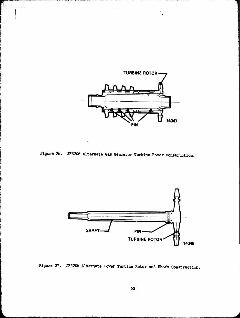
A further cost savings can be realized by using an alternate construction for both the gas generator turbine rotor (Figure 26) and the power turbine rotor (Figure 27). The gas generator turbine rotor is no longer piloted on and socially pinned to the shaft to transmit torque. This is accomplished by the same method of radially pinning the rotor to center it and to transmit the torque as is used for the com- pressor rotor. This design also eliminates the nut, locking ring, threads, and slots on the shaft.
The power turbine rotor alternate construction is press-fitted in the shaft and pinned at assembly. This design eliminates the key, key way, threaded shaft, and self-locking nut of the baseline design. In addition, the power turbine rotor be- comes a solid disc which allows a thinner disc (less weight) to be used with the same margin of safety.
1*9
1 «I
+> 3 ? C\J CO i ■p
0) B
•H H V 3
pq
V0 o CvJ
o c o 01
CJ
50
m 4) Q
V
* e ■p
CM
CM CO
•-5
0)
(A 0)
PQ
vo o C\J to
1-3
o a o 03
IT» CM
51
fl
TURBINE ROTOR
Figure 26. JFS206 Alternate Gas Genrator Turbine Rotor Construction.
SHAFT PIN-
TURBINE ROTOR 14048
Figure 27. JFS206 Alternate Power Turbine Rotor and Shaft Construction.
52
_ „„.^MU^t
w^r— '"— «OTmfff
The cost differentled for the two alternate rotor constructions compared to the baseline rotors provides material dollars savings of $31.00 and standard labor hour savings of 0.557. When the price differential is applied to the baseline JFS206, it amounts to a savings of 1.2 percent. When it is applied to the turbine rotors and shafts involved, the difference becomes 10.7 percent which is consider- able on a component basis.
DIRECT-DRIVE STARTER
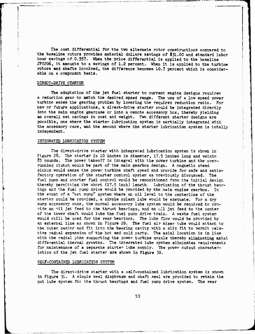
The adaptation of the Jet fuel starter to current engine designs requires a reduction gear to match the desired speed range. The use of a low speed power turbine eases the gearing problem by lowering the required reduction ratio. For new or future applications, a direct-drive starter could be integrated directly into the main engine gearcase or into a remote accessory box, thereby yielding an overall net savings in cost and weight. Two different starter designs are possible, one where the starter lubrication system is partially integrated with the accessory ease, and the second where the starter lubrication system is totally independent.
INTEGRATED LUBRICATION SYSTEM
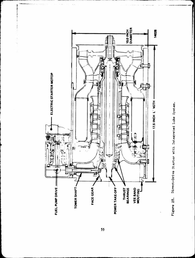
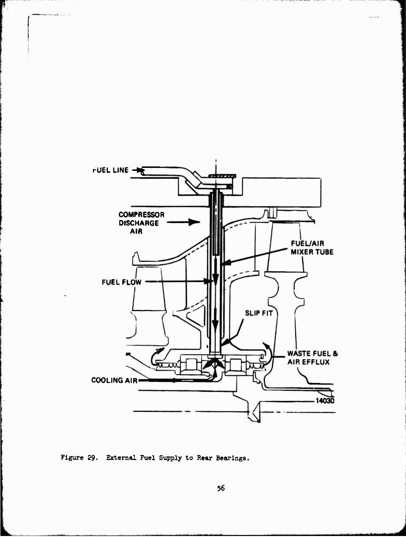
The direct-drive starter with integrated lubrication system is shown in Figure 28. The starter is 10 inches in diameter, 17.5 inches long and weighs 85 pounds. The power takeoff is integral with the power turbine and the over- running clutch would be part of the main gearbox design. A magnetic speed pickup would sense the power turbine shaft speed and provide for safe and satis- factory operation of the starter control system as previously discussed. The fuel pump and starter fuel control would be repositioned from the initial design thereby permitting the short (17.5 inch) length. Lubrication of the thrust bear- ings and the fuel pump drive would be provided by the main engine gearbox. In the event of a "vet sump" system where an oil level to the centerline of the starter could be provided, a simple splash lube would be adequate. For a dry sump accessory case, the normal accessory lube system would be required to pro- vide an oil jet feed to the thrust bearings, and an oil jet feed to the center of the tower shaft would lube the fuel pump drive train. A waste fuel system would still be used for the rear bearings. The lube flow would be provided by an external line as shown in Figure 29. The fuel air mixer tube would attach to the outer casing and fit into the bearing cavity with a slip fit to Permit rela- tive radial expansion of the hot and cold parts. The axial location is in line with the radial pins supporting the power turbine nozzle thereby eliminating axial differential thermal growths. The integrated lube system eliminates requirements for maintenance of a separate starte1" lube supply. The power output character- istics of the Jet fuel starter are shown in Figure 30.
SELF-CONTAINED LUBRICATION SYSTEM
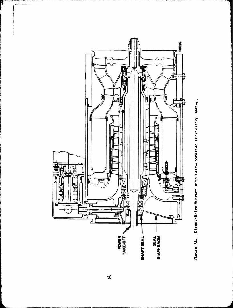
The direct-drive starter with a self-contained lubrication system is shown in Figure 31. A simple seal diaphragm and shaft seal are provided to retain the pot lube system for the thrust bearings and fuel pump drive system. The rear
53

^.4-:-*J-.MT?»'>^';-J^^--'■+■-■-■■!-' •■<T»-»-8 -'- '. . "W B -i-l^ii,ST^^p™
bearing lube system as used for the integrated system is retained. The added seal diaphragm and shaft seal will add 1.1» pounds to the starter weight for a total of 86.h pounds.
5«»
•^ S ui O
I p w
T) <U -P B) V. bC 01
■P c
■p
t
•H
•H o
00
55
i-UEL LINE -*g
COMPRESSOR DISCHARGE
AIR
FUEL FLOW
COOLING AIR
Figure 29. External Fuel Supply to Rear Bearings.
56
■i^M^^Mi
80
70
60
(Ä 50 OQ -1
* ÜJ 40 3 O QC O
30 h-
20
10
0
HF
V T DRQUE
p UTOUT— »EED ANGE
^W~V /y^
v/v
160
140
120
oc 100 uj
O 80 uj w
oc
60 i
40
20
0 10000 20000 30000
OUTPUT SPEED -RPM 40000
14046
Figure 30. Direct Drive Starter Torque and Horsepower Characteristi es.
57
§ •p 09
* c o
•H
o 1-1 u
a •H <«
■P C o o I
4-4 H 4)
CO
V
t a)
•H
*? ■P O V
Si
I ■H lb
58
SECTION VT
GROWTH POTENTIAL
COMPQiJEirr IMPROVEMENTS
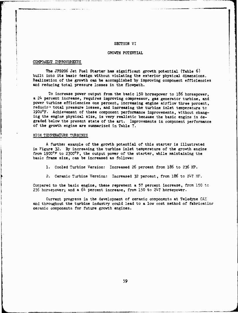
The JFS206 Jet Fuel Starter has significant growth potential (Table 6) built into its basic design without violating the exterior physical dimensions. Realization of the growth can be accomplished by improving component efficiencies and reducing total pressure losses in the flowpath.
To increase power output from the basic 150 horsepower to 186 horsepower, a 2k percent increase, requires improving compressor, gas generator turbine, and power turbine efficiencies one percent, increasing engine airflow three percent, reducir» total pressure losses, and increasing the turbine inlet temperature tc 1900°F. Achievement of these component performance improvements, without chang- ing the engine physical size, is very realistic because the basic engine is de- graded below the present state of the art. Improvements in component performance of the growth engine are summarized in Table 7.
HIGH TEMPERATURE TURBINES
A further example of the growth potential of this starter is illustrated in Figure 32. By increasing the turbine inlet temperature of the growth engine from 1900°F to 2300°F, the output power of the starter, while maintaining the basic frame size, can be increased as follows:
1. Cooled Turbine Version: Increased 26 percent from 186 to 236 HP.
2. Ceramic Turbine Version: Increased 32 percent, from 186 to 2l»7 HP.
Compared to the basic engine, these represent a 57 percent increase, from 150 tc 236 horsepover; and a 6k percent increase, from 150 to 2*+7 horsepower.
Current progress in the development of ceramic components at Teledyne CAE and throughout the turbine industry could lead to a low cost method of fabricatinr ceramic components for future growth engines.
59
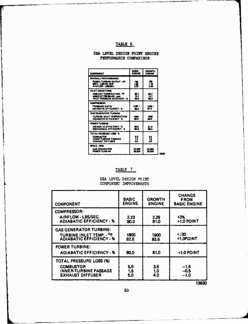
TABLE 6
SEA LEVEL DESIGN POINT ENGINE PERFORMANCE COMPARISON
COMPONENT ■ASIC ENGINE
GROWTH ENGINE
OVERALL PERFORMANCE: POWER TUMI« OUTPUT ■ HP. ■SK-LM/HR4MP AIRFLOW- LSS/SEC
in lit l.l« in
INLET CONDITIONS: AMSIENT TEMPERATURE ■ °F AM«IENT PRESSURE PM
I INLET PRESSURE RECOVERY - %
ML7 147 EtlO
U.1 14.7 •HO
COMPRESSOR: PRESSURE RATIO ADIAOATIC EFFICIENCY ■«
1S»:1 sao
141:1 (1.0
GAS GENERATOR TURilNE: TURSINE INLET TEMPERATURE AOIAIATIC EFFICIENCY - %
ISIIO (£S
IK» M
POWER TURilNE AOIASA .'IC EFFICIENCY - * MECHANICAL EFFICIENCY *
■0.0 M.0
•1.0 •S.0
TOTAL PRESSURE LOH » COMSUSTOR INNER TURilNE PASSAGE EXHAUST DIFFUSER
S.0 t.B 5.0
IS 1.0 4.0
SPEED-RPM GASGENERATOR POWER TURIiNE
43.800 ».000
43.S00 20.000
13S2S
TABLE 7
SEA LEVEL DESIGN POINT COMPONENT IMPROVEMENTS
.
COMPONENT BASIC ENGINE
GROWTH ENGINE
CHANGE FROM
BASIC ENGINE
COMPRESSOR: AIRFLOW-LBS/SEC. ADIABATIC EFFICIENCY - %
2.23 80.0
2.29 81.0
+3% +1.0 POINT
GAS GENERATOR TURBINE: TURBINE INLET TEMP. • °F ADIABATIC EFFICIENCY - %
1800 82.5
1900 83.5
+ .00 +1.0POINT
POWER TURBINE: ADIABATIC EFFICIENCY - % 80.0 81.0 +1.0 POINT
TOTAL PRESSURE LOSS (%) COMBUSTOR INNER-TURBINE PASSAGE EXHAUST DIFFUSER
5.0 1.5 5.0
3.5 1.0 4.0
-1.5 -0.5 -1.0
60
13930
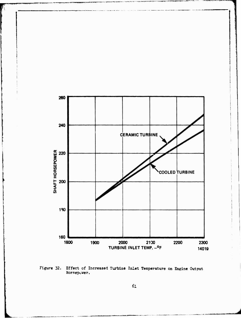
160 1 1800 1900 2000 2100
TURBINE INLET TEMP.-°F 2200 2300
14019
Figure 32. Effect of Increased Turbine Inlet Temperature on Engine Output Horsepower.
6i
■wgpnappi■ fffwif 'u**!'-'■'' ' ,T**~ "WPiwpw II- ^-^^^^^W^^M
SECTION VII
CONCLUSIONS AND RECOMMENDATIONS
CONCLUSIONS
The preliminary starter design, as shown in Figure 33, can meet the objec- tive of an $8000 unit selling price. The starter, designated as JFS206 Jet Fuel Starter, is 10 inches in diameter, 20 inches long, weighs 98 pounds and produces a maximum output of 150 horsepower. The starter is a two shaft engine with a radial air inlet and axial exhaust, a reduction gear, a fuel pump and control,and an electric starter motor. This lightweight, compact unit contains all the features necessary to perform safe and reliable starts of the main engine. Th" starter is capable of operating over an ambient temperature range of -65°F to 130°F and at altitudes up to 8,000 feet. It incorporates containment provisions to preclude damage to the aircraft in the unlikely event of rotor burst.
The design incorporates the following low cost features:
- Low Speed Rotor Design with Die Cast Aluminum Compressor Rotors
- Low Speed Rotor Design Permits a Concentric Shaft Design with Each Rotor Simply Supported on Two Bearings
- Concentric Shaft Design eliminates Expensive, Complex Exhaust Elbow
- Simple, Annular Vaporizer Combustor with only three fuel injection pipes and three "tee canes"
- Die Cast Aluminum Housings
- Simple, Cylindrical Rolled Aluminum Outer Casing
- Rolled Steel Containment Ring
- Radial Pin Joint Construction
- Electronic Fuel Control with Motor Driven Metering Pump and Engine Driven Centrifugal Pump
- Commercially Available Outboard Engine Electric Starter
- Pot Lube Reduction Gear and Thrust Bearings
- Waste Fuel Lube Rear Bearings
- race Gears in Accessory Drive
- Minimal Use of Expensive High Temperature Materials
Preceding page blank 63
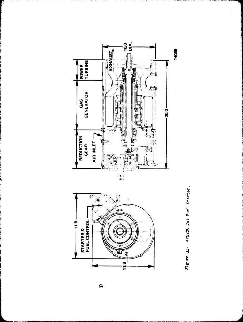
to
u
CO
c\j
•H
61»
- Maximum use of cast components to minimize Machining.
Two additional starter design approaches were prepared and compared to the JFS206 design to Justify the basic design approach. A low speed concentric shaft engine design, although having more compressor rotors, permits a simple con- struction and low cost fabrication techniques with an overall r3duction in total parts and total starter cost.
RECOMMENDATIONS
It is recommended that a full scale demonstration engine, (Task 8), incor- porating all the starter systems, be built and tested to prove the validity of the low cost features of this study. To build logically to this objective, seven discrete component tasks have been identified. It is recommended that they be accomplished as a necessary part of the 'Aill scale demonstrator program.
Task 1: Combustor Rig Test
In return for low cost and volume, the compact, simple combustor design with only three fuel nozzles and three "T canes" represents the only high risk aerodynamic components. Consequently, a combustor rig test program should be initiated.
This rig testing of the combustor will provide operational definition and resolution of the following parameters:
1. Combustor Efficiency 2. Pressure loss 3. Temperature Distribution Factor k. Minimum Temperature Rise 5. Radial Temperature Gradient 6. Fuel Injector System Efficiency
Task 2: Gas Generator
A full scale gas generator should be designed, fabricated and tested to demonstrate satisfactory thermodynamic and mechanical operation. The gas generator testing will provide confirmation of the:
1. Air Flow 2. Compressor Pressure Ratio 3. Compressor Adiabatic Efficiency U. Turbine Inlet Temperature 5. Turbine Adiabatic Efficiency 6. Combustor Pressure Losses
65
i
J
HJÜH4I ."-'J 4I.-L
Task 3' Waste Fuel Lube System
A bearing test rig should be designed, fabricated and tested to demonstrate the waste fuel lube and air cooling of the rear roller bearings. The 25 hours of operation and 2000 starts required by the JFS206 can readily be demonstrated using this rig. The proper fuel flow rate will be determined during rig operation. The bearing test rig will be used to:
1. Determine the proper fuel lubrication flow to the bearing.
2. Determine the cooling air flow for the bearing.
3. Demonstrate the capability of the bearing and lube system to complete 2000 cycles of operation.
Task k: Reduction Gearbox Rig Test
A back-to-back gearbox test rig should be designed, fabricated and tested to demonstrate the power transmission hardware and its lubrication system. The engine hardware, in order to meet the cost objectives, will use un- ground gears as received after heat treatment.
The Rig will be used to:
1. Evaluate the heat treated gear distortions under varying conditions of speed and torque, simulating actual points of engine operation.
2. Establish proper gearbox oil level.
3. Confirm operating capability at different altitudes.
k. Establish oil baffle design requirements (if needed).
Task 5: Die Cast Rotor
The die cast rotor requires the application of die casting techniques to an axial rotor fabrication. The revisions to the rotor design to permit successful die casting will be established during the rotor fabrication phase. The die cast rotors will be:
1. Subjected to spin pit testing to establish their structural integrity.
2. Vibration testing to establish blade frequencies and endurance limits.
3. Gas generator testing to establish aerodynamic performance.
66
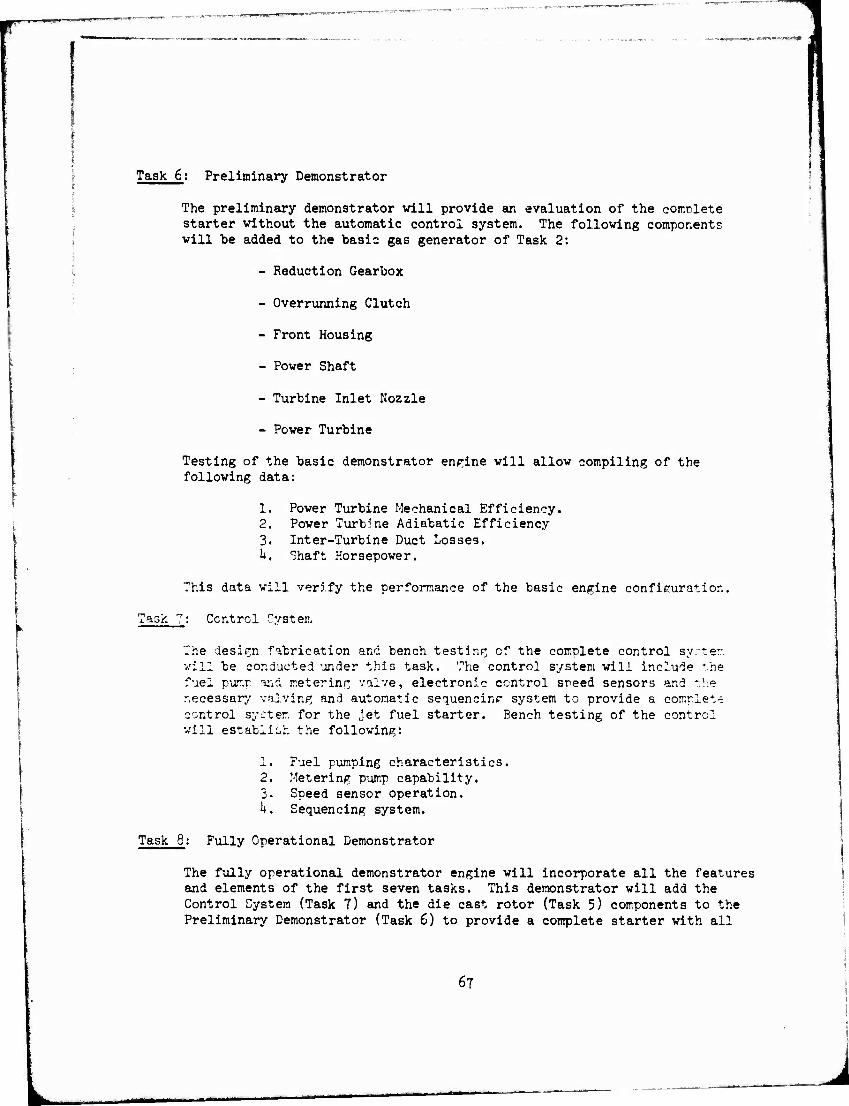
1
Task 6: Preliminary Demonstrator
The preliminary demonstrator will provide an evaluation of the comclete starter without the automatic control system. The following components will be added to the basic gas generator of Task 2:
- Reduction Gearbox
- Overrunning Clutch
- Front Housing
- Power Shaft
- Turbine Inlet Nozzle
- Power Turbine
Testing of the basic demonstrator engine will allow compiling of the following data:
1. Power Turbine Mechanical Efficiency. 2. Power Turbine Adiabatic Efficiency 3. Inter-Turbine Duct Losses. h. Shaft Horsepower.
This data will verify the performance of the basic engine configuration,
Task "7: Control oyster.
The design fabrication and bench testing of the complete control syrter. will be conducted under this task. The control system will include *he fuel pur.r and metering valve, electronic control speed sensors and the necessary valving and automatic sequencing system to provide a comnlet-e control system for the jet fuel starter. Bench testing of the control will establish the following:
1. Fuel pumping characteristics, 2. Metering pump capability. 3. Speed sensor operation. h. Sequencing system.
Task 8: Fully Operational Demonstrator
The fully operational demonstrator engine will incorporate all the features and elements of the first seven tasks. This demonstrator will add the Control System (Task 7) and the die cast rotor (Task 5) components to the Preliminary Demonstrator (Task 6) to provide a complete starter with all
67
L J
1
critical low cost features. This unit will demonstrate the following:
1. Functional ability of the starter to perforr. safe starts.
2. Checkout of the automatic sequencing system.
3. Confirm engine output power.
h. Evaluate low cost structural features.
5. Confirm total nackage weight.
68
APPENDIX A
ASSEMBLY DRAWINGS AND BILL OF MATERIALS
The Jet fuel starter design is defined by the assembly drawing and a bill of materials itemizing the total number of parts required. Figures A-l through A-3 show the engine design, and Figure A-U defines the bill of materials for the yelected JFS206 starter.
The same data was prepared for the two alternate designs, JFS206 A-l ari JFS206 A-2 to provide a basis for detail cost estimates. These drawings and till of materials are shown in Figures A-5 through A-10.
J
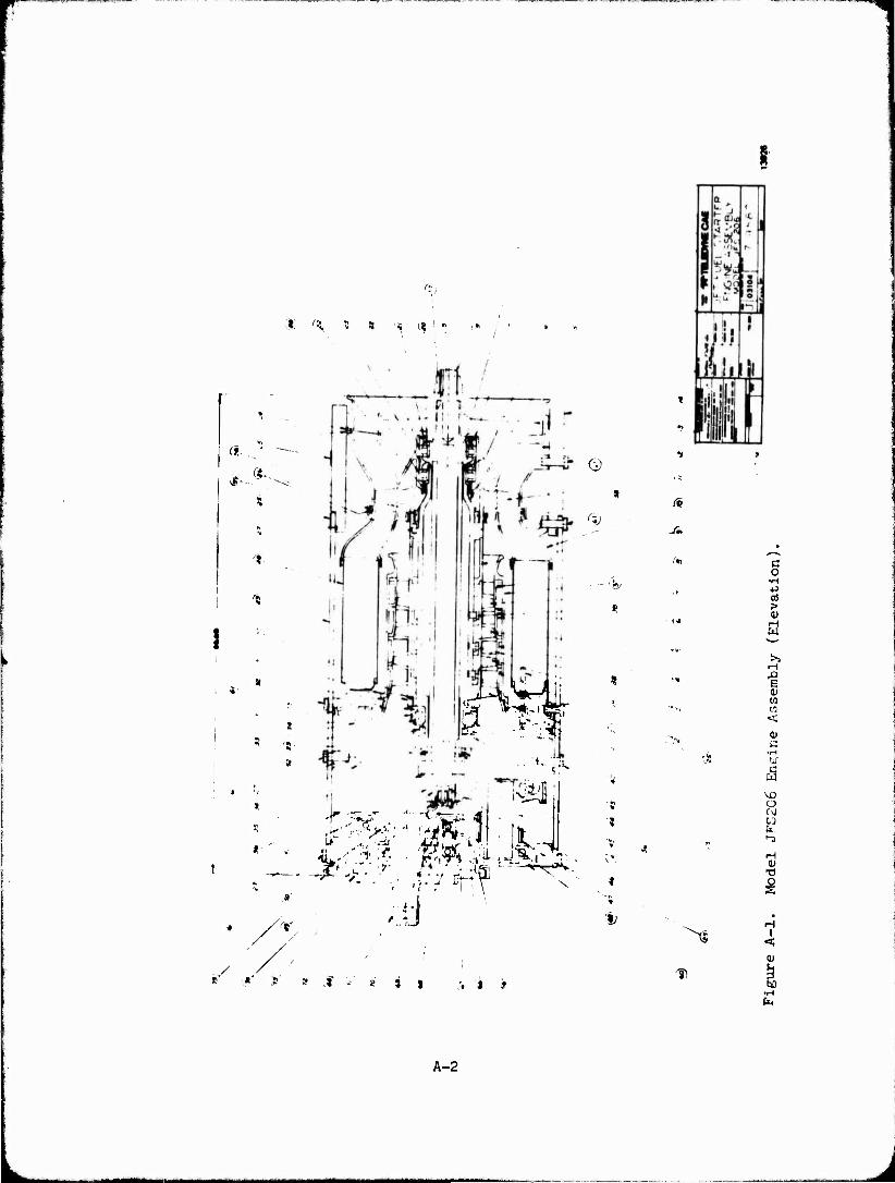
"• s
Q
<';;
*• .=-
^
J ' »' < .'.IS
X
'i
A,
>*
D
a o
>
! w w <
13 •H faC
ä O
«e •-3
5
i <
I«,
A-2
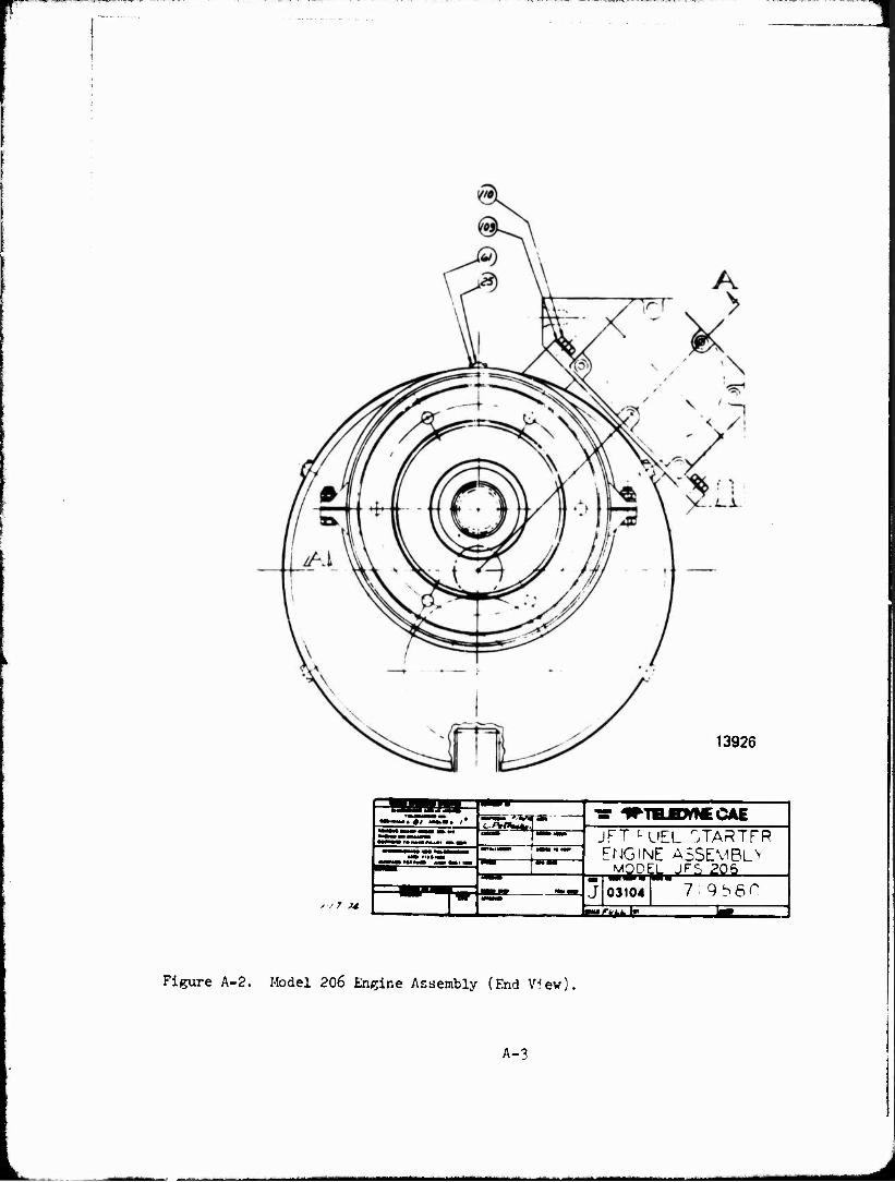
13926
■7 ?4
TüTSZ.. ,'
■ fvraa—
CAE JFT "-UEL "TARTFR ENGINE ASSEMBLE
MODEL JJFS 205
JJ03104 7 9S6f" tt—rtkkl"
Figure A-2. Model 206 Engine Assembly (End V5ew),
A-3
M^HI^
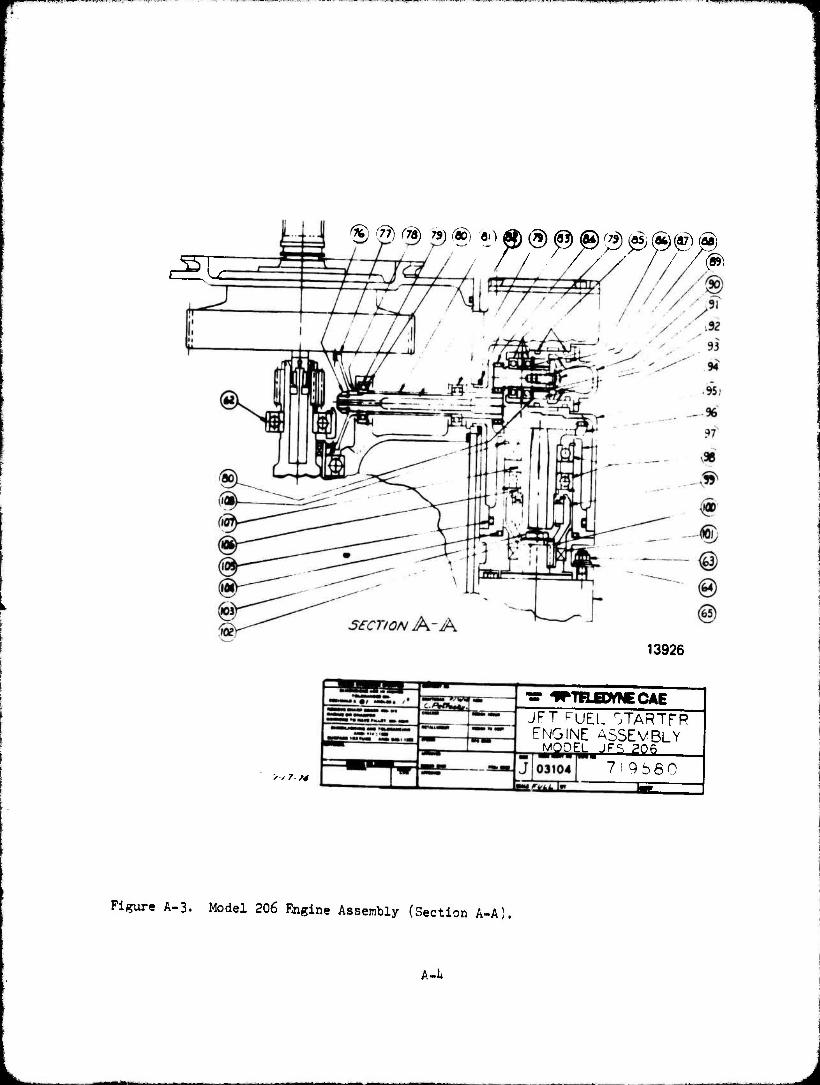
. ,i.» « ii» »UM i ,
cSC ® @ f73) 79) (®) a
1 i gg-/-/ /-
13926
/ ;7 ?4
JFT FUEL OTARTFR ENGINE ASSEMBLY
MODEL JFS 206
7i 9b60
Figure A-3. Model 206 Engine Assembly (Section A-A).
A-l*
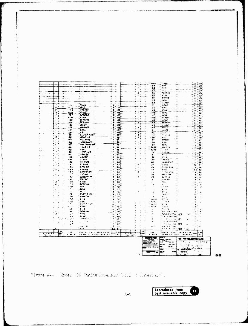
-t—*■
* ■ j ■' ° •/ < / */M« / Q [«Otr l'*9 '«**«» •'S*. . , tfirta, ■107 3**te* ,oa e,na
■IOS fD"*//vf
to* 'StlNd
'Of Boif ■ at tmama 101 StAL oo "I* »» CLUTCH »iff
M «MM« -»» HOuStHi -«• jlA*s**rr tT 'ott csmmari M ~s*S'Nt
i# it*!. M "flirt
■#i 5««#« -»0 .-;«« ■31 S<.«w t* ItiHtt f t *'«• a* J*K#*
■at »'»'«« ■ !* ai**3»*rr
SS ■O't-ta • , ZftUKAßT • a smut*
to r N* •i at tuna
■ -a rtf •» at" ** HUT •s v a*»e «•-■' '# äQ**T*t •s t •* •e U'L
%—Arr *v*> - 'i # '.« -» #--.« .« ««/•* * - * v4 «* n*e
;• 01» ■ »'
139»
•lrure /■.-"*. .-.odei
Reproduced from best available copy.
L_
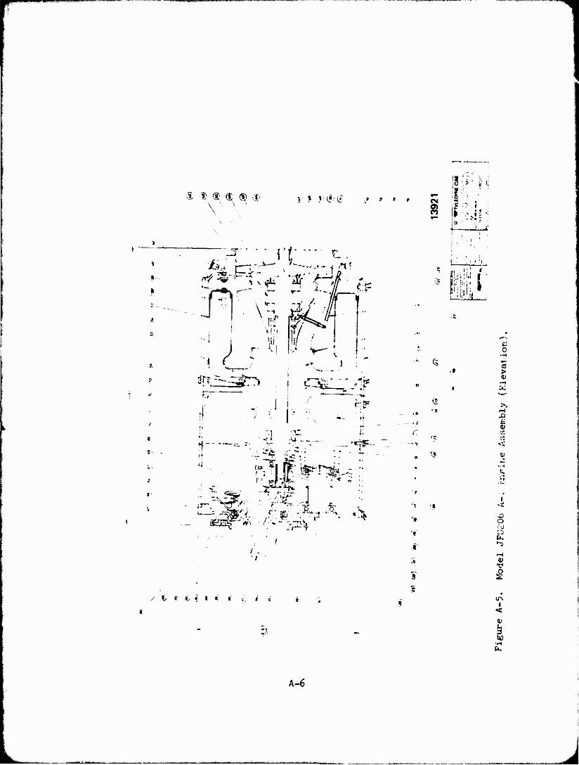
A I ® d; (S cr \ ' \ ' "
» .*><?>£
\- Ij-f
\4i? fr i i
j ^ t.
Ai -.~
• g,
~ ' " »{
ir" 'it
FT *— J"I* -f ■*• f\i_ C *
^
';
t » i ( j i t i JT s * ;
It':'*' N CM a . ■
4. ^
1
.' fa . 1 '
■ 1 '!
pi» i<:
(5
<S
■ •
't
"f *
I i
c c
>
0)
■--4
ti.
o rg C'J
I <
(JO •H
A-6
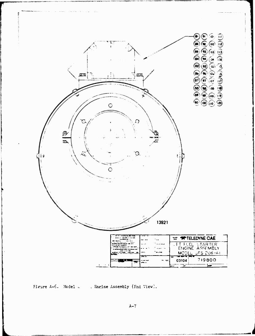
13921
/• •*« ?•«•■.« V«' -*• —" ■•■
•ar ITTELEDYNE CAE
irtflliiiN ■■* •« Mi BWAT
»IT FIEL STARTER
ENGINE ASSEMBLY MODEL JF5 ro6-*i
«..., O3104! 719800 [ w
1- 1—
Figure A-6. Model c Engine Assembly (End View).
A-7
-
L
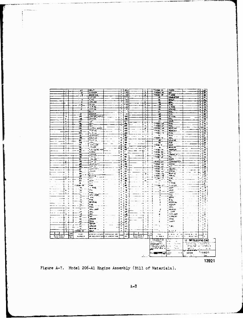
1 - *s •OLT >ftf . f'MH4 cOrtK 3 •0 | - >» *«5Ht« M» J ''tSAO « «VT J 5» ' • i» • f *t NO a ] »MlC'f T UM J J» 5'f'NS i }f 1 5» COMiulTO» J J7 • «.iXii <• l -Jfc I(0U1? J M
' i .»♦•CM i iS C 35 M»t I JJ i I» * so r '4 t - J» »IN6 5 J»
J S *•».» 1 -51 V »la* ft !J / 3 • N4 ^ 1 J« J»ACI« 6 n Be- I ■|i Mfc. ■ »i ! fO «JSNiTI
' ■
10 i -JO »IWG „ X — 1
4
09 iTAK'fff «SSf Of
M
i ** •0 »'«i. 6 49
cm w*S-It I «• • !•«, t> « 4 -101 .J''' 4? 4CA» b 47
** so« t
- ^»J*0-4» RiM6 <* 44
45 .OJ 't'
101,
/Ol '
- 9SAO *-' »IN& ., r .0« ..*,?<.<■ 4S9f
—i ^<«5S0 Ul «»»■»» »7 44
— 31 » >'*!Bo 4« «l*»i 7 4|
»I I ' 43«o.->J T 4t .ft -c«:«*'- >0i «i »ia«
«"■ 1. ' " T 4.
1- "° if*-'
-'if*
8 LOO
rts ■ i I -H« -1 7 40 1
-~ •f r " »C.'HiS ^ M
. . ■"' -
e I*.L | ° i" 1
--' _4-,-* - "ftM» ' 7 S*
, ••» .. . «.»J! £ . t :v:. I *»JBO■'*
H«»<oa i j« ' M
M L OiN -54
33
3«
, : ■»#
„AS*.-» 1 j 'MSÜ-V >WiO »I:- » *t
-P4.EI » ;« '
9i s
J J'
1 ^ ^ M : * iS * * 1 . "fffftO t>»
' :4l»7£»*tl4l•,■ } 30
»» it*#i*-rT B I»»
d 5-
[__ sc»ew ■ » . 1 » I T'»50C *« [•v ! a
— — -- •w- •- - I . ... H
.►-if» [- - \ ■ at" r_. L'l • 9586-.% j KAA-%ft _-' tf
(M !!■••.. 1
fir:-:1- • - •1«! £4 '
— - r-2 H
-9
\ -'?; ~ —_■_..
... .•__
!.' es r
4- 4 + * s.»j»ie.>' l-uViiii
R?- - - - ... . *.. ^ * : ;*»■"[ * e | it**
.... , l - ! •!< -—— i : ■T jHAr*
r+-r- ( ! - I
1 t
Mt*l LAMD
-EAl — » .-« * .
.sä . _.'.+.- »IM f
>f*h ÜMD "
_jt> "üiirT '.
»IN6
»•»a» i
■UN
• 1?« ' •">:f _ !" 1 I « I *.>•." *'
' :i—" ■ ... - ...
ft?
-** «J.
i 4
• • 4
4
'3 ii _♦ | 3 ^ rtf *«IWö it u . ■ + ; 1 *i>tw
'» J i i : . ««*- 1
-c : H
?1
M
'C j -CvJIMCi f'. 1 *
^_ _ - — £
-- _ .1 j • l.=Ä»i»
i • I .'..«•(.'HT
• II ; t -»«APT
' :■ ff-]
1« t
I" .
£
hi ' 1 ;•*« i - >
J ■O.T i N.r.-.F
l l CODI iM ** ■ 0 NtiKtl«
«oaiM'iiTuif O* Df *C «.»TON e a c u a I a t " o
10«f (iND NO
1 1 s Mm * '."* .'.. "1 ti« • * ■ H .. J »
0 , ■[* ' no (I'M
s a * i »I 0 t> 0 I I Mil 0
*"'**■ ' * •2 ^TTB-ECVNECA E
i,
-i.
-T *" ——■-•—
ÜJI04
13921
Figure A-7- Model 206-A1 Engine Assembly (Bill of Materials!
A-8
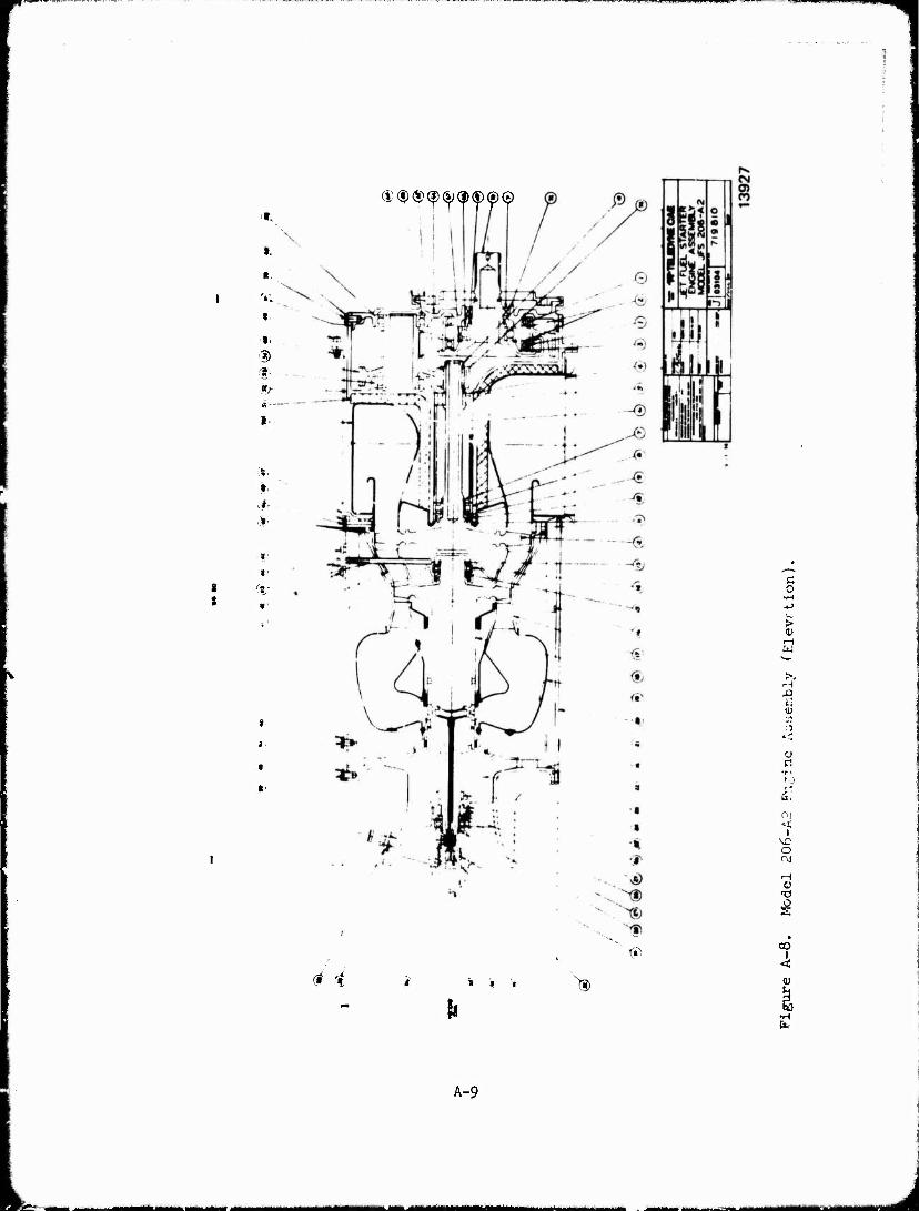
.1V J'-'.1' .*l»WffM..ip«! "
(S>®®®©®®®©
*.
v.. t
» 3> $■■
I
t
f i
W
<* * » * '» 3>
c o
> 91
Ö
l-H
■i u o
El
I
o rvi
0
OO
4
& •H
A-9
M^^WM« MMbMUMHliiHiiKj
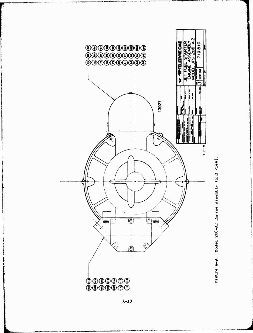
> •H > xi
,-1
en
5
i
0) -a
<7\
4
■H lit
A-10
L
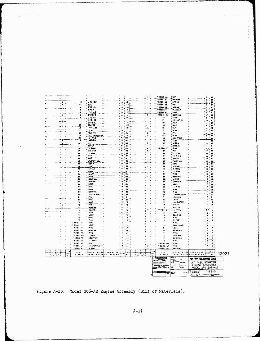
4 1 .»S-tl 4 - <y «Ot' ; V« K»
J }-*»' 4 .'» Nj 1 1'OCft
~* »45"tt ' £ :c»c«
:J SMCH .• -M..I« ^»41
i» . «an •<• *i .iXtJsagtMC
|C4 c »«* 1 ' :.\ «•»«•» < M *«r J > KM*
♦h «Mr
M :u» M 4-i|_C
f
* f
AC
*H *r 'A
* 5 ■u
t at • s •
1 * * ■ m • «* « «' •
* * - «i . «i * ' i
:»' . 4C
s * 3f
s «e • r ä *.
13927
Figure A-10. Model 206-A2 Engine Assembly (Bill of Materials).
A-ll
?»1™»!™» L 1 .. .LI ÜWHWP
APPENDIX B
DETAILED COST DRAWINGS
Detailed cost drawings were prepared for complex parts where the starter assembly drawing did not provide adequate data for estimating labor and material cost. These drawings are shown in Figures B-l through B-9.
B-l
J
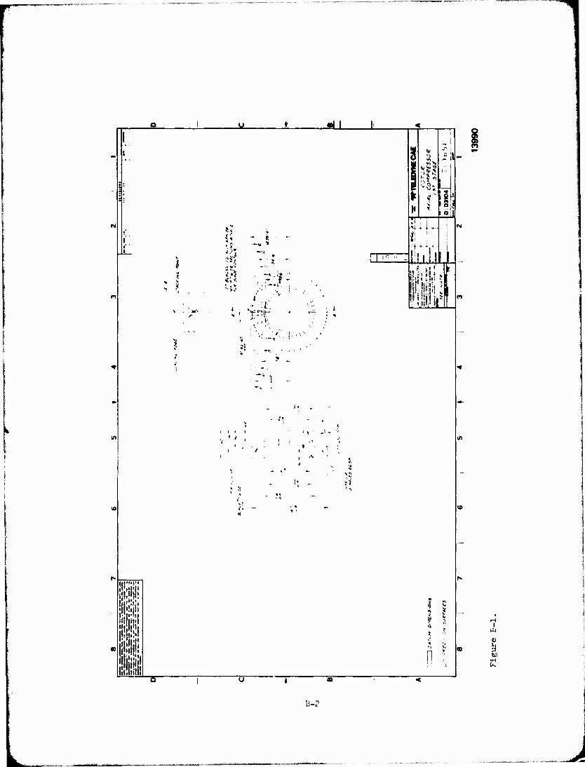
m mm mi:»
I ,»
1 i 5>J «;<
- * —« »
?•*:
- /i
iii i
3 v »I'M
<t >« 9
<i o •.
= 11. - i
a a
-n 4 ♦ +
1 *
ll <
mi
I HI
0)
!) 60
Ii-2
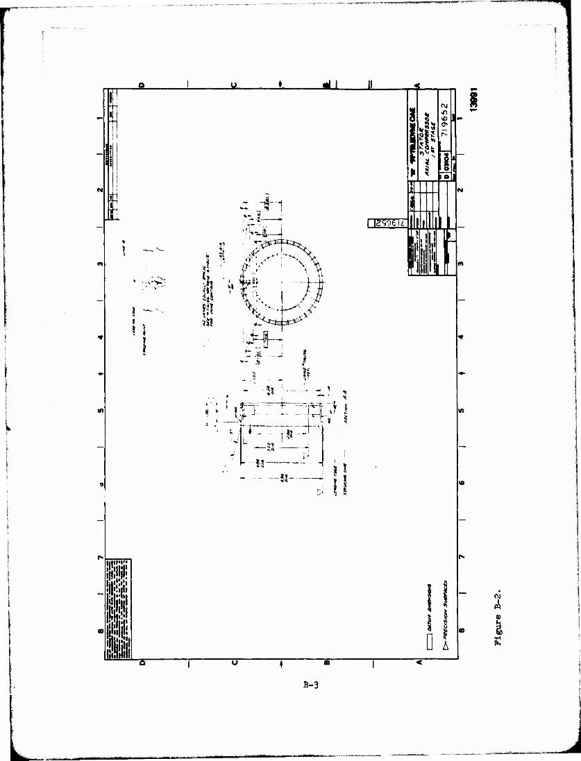
in
III"''" if I !
'if
o i o ♦ m I1
^ 1 1 H
{ ! |
;
M
r •L
•— !3 1 «j _... 1
«
* * ? $
>•
*
i $
Si -■■*
a*1«' ' V-- 1
* i - '?L ' f
H - ji—
*1
. i _V
* ,n
rr «-1
M >i
\ZS06\L
3
J
W
iii
I-
IO
D A
m
in
OJ
B-3
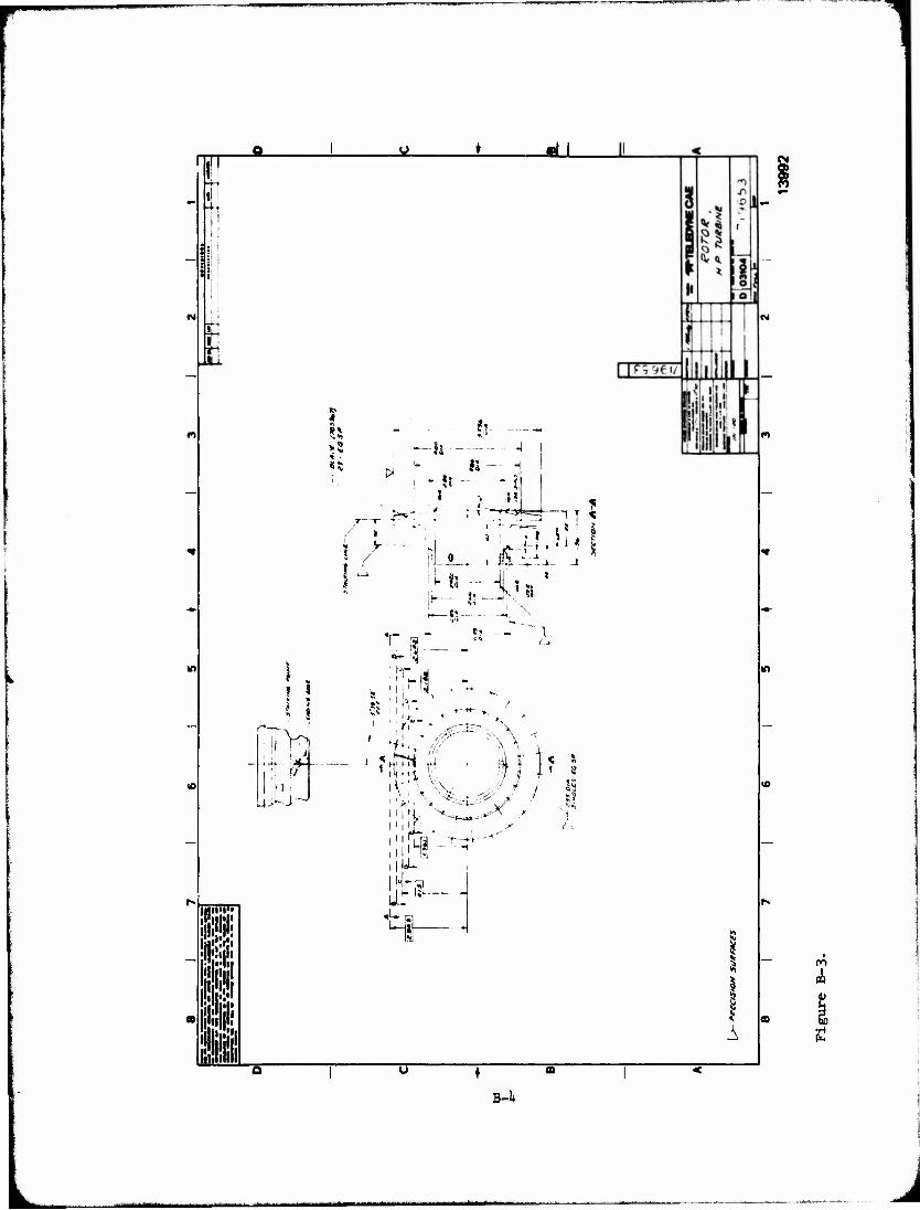
I -H
?!
m
m
m m lii ! a
iTv,
uitu-
4 g
«5 tJ IS 4
1 - ?3
5 T—f-
> ?-'
-Jk ??
T s" ■ Pi - -
Ift- '4 1 'T ii
ft
f- IS- K " :i $S~ "
' ?i ' |l|.H i
v v iiV <
I f J-J—
- ■*■< - '
1 ! A
m
in
on
B-l»
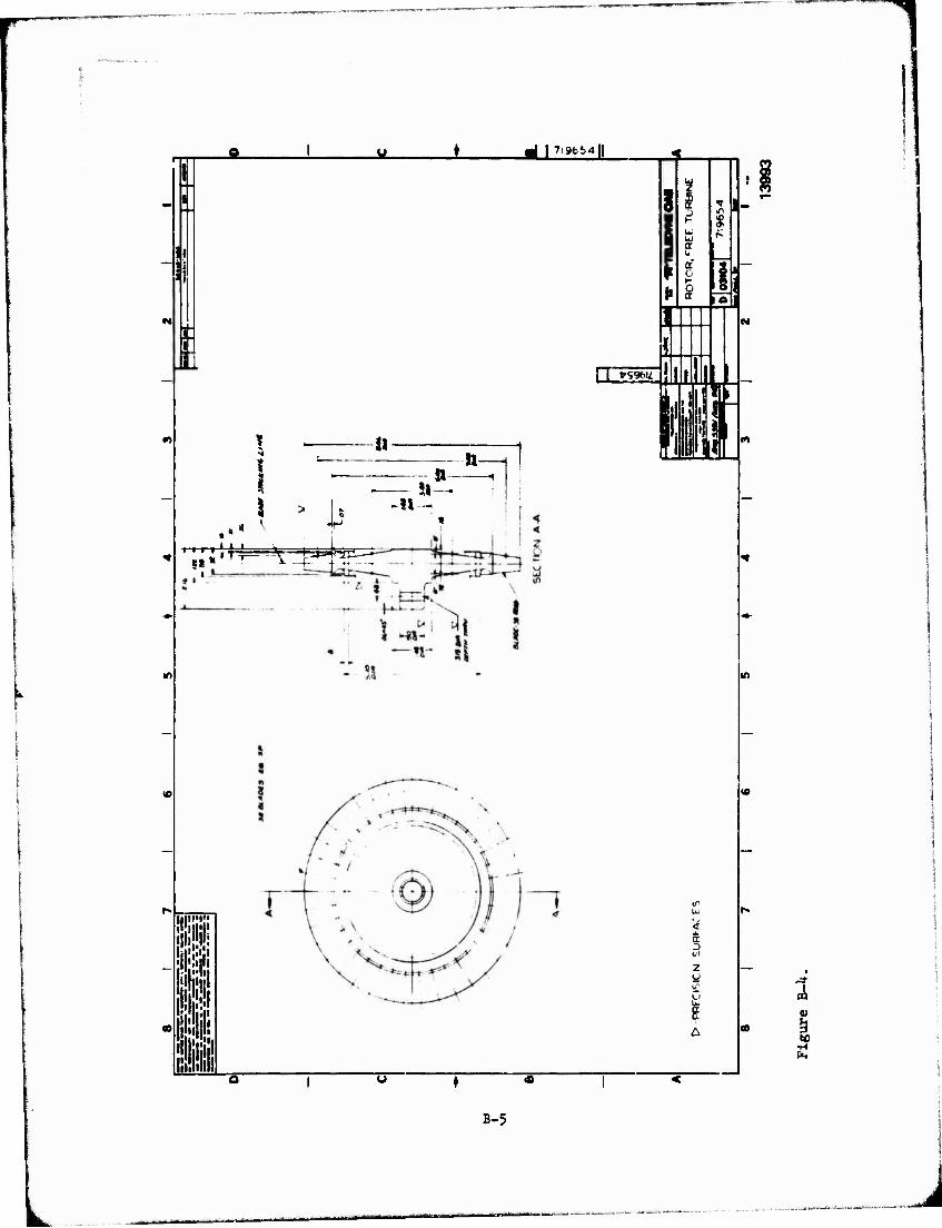
in
u n
5« • i »■ —p | .. ......
ml | 7i9t>54|
III"'!"
el
I I »996M."
8
111 ■
I
»-
a.
2 Ü
0
N
in
4
B-5
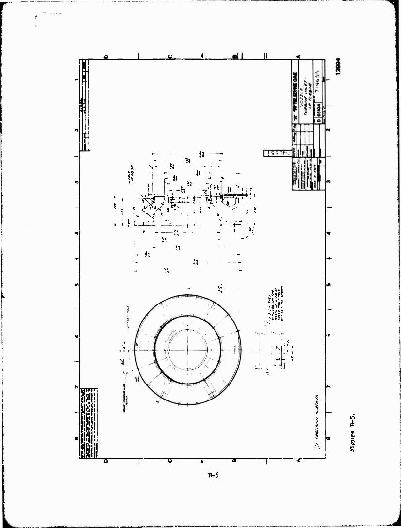
: !
IB «ill %
J m fir
!] r it » !
3l
*i
!?
Ii - i-
- -?t " —.'?»i|, i, *,.,
« *
»»
- v
1 L '
Si
\ V
*«
ft €
N
US'
"-fj
♦ " CO
B-6
A
lm
<4
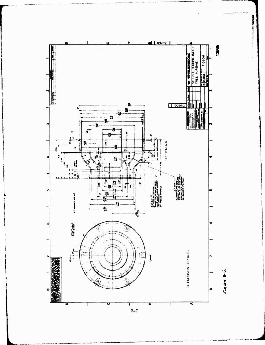
■< I Tiafe&fe H
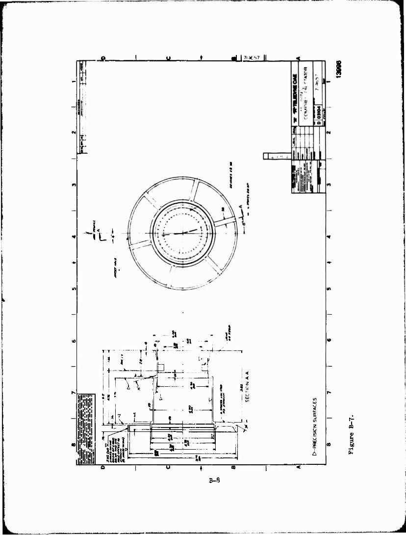
d >71*
t
S
I1
T T
?» ,!
u ÜIIIM" s B i! I I: I III Ulli!
I hü
T
U= ^€
llr
1 i
i <
* < z
? 3^
4«
P^^r K-- xr>*
-5S Si
1
cr D l/>
2 O üi V
•H
B-8
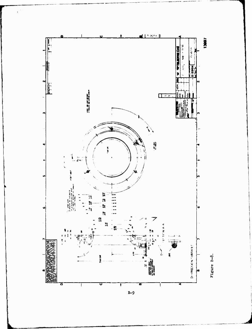
d r-H-Hi
fep
1! ■in ill
3 8
a-
iSJj For
w. Ml Mi IF 111
2
Z
A
oo I
m
60
B-9
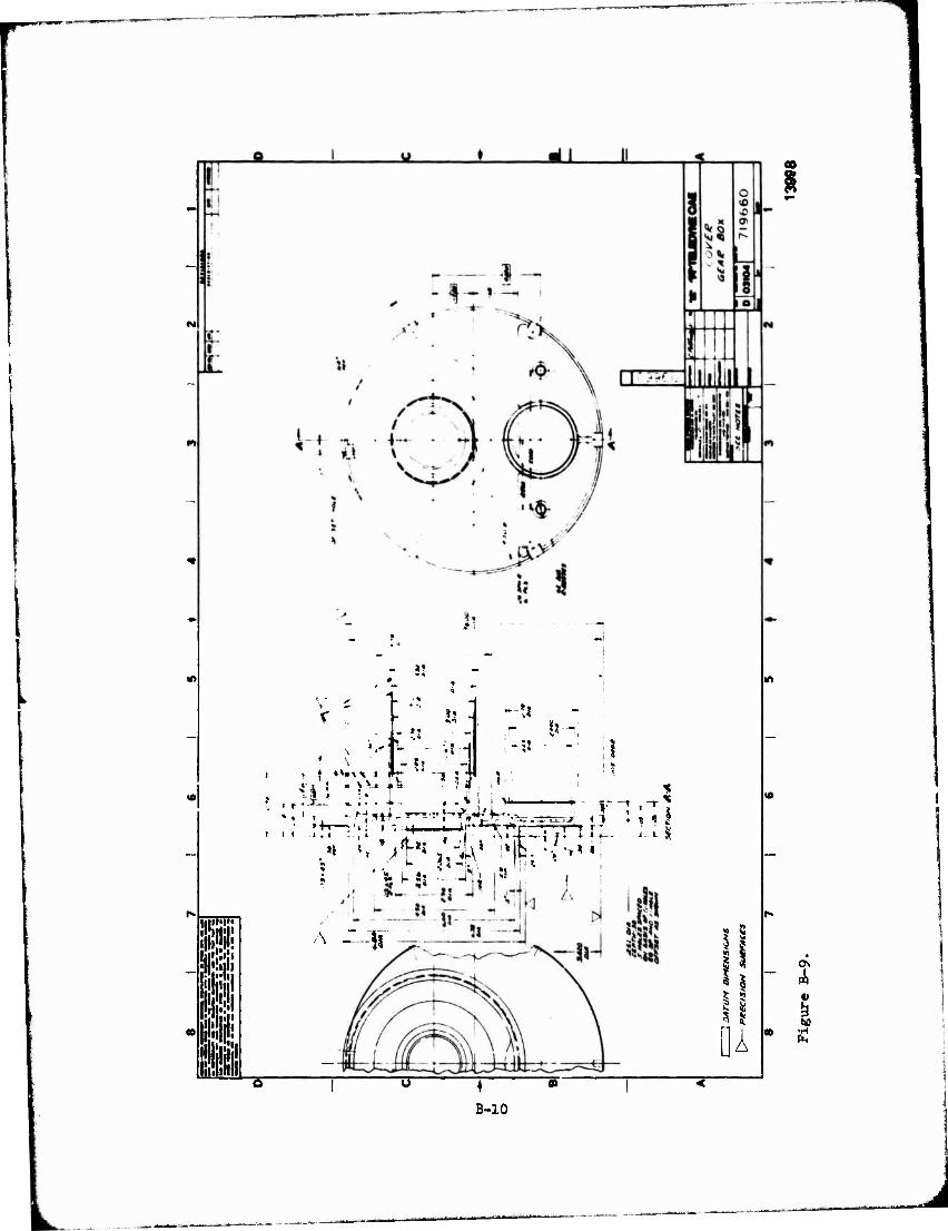
! i '••ill
m
nil I
**
V'5 !l -i
1- ** '- - i! H - ?» -
ji ! • J v» f* • ?« "I * •* 1 i
i ii i.i
_ »j
;*
, . * I i V
.i : , i ' 71 ' J j.' .\tJ—; T- 4
A ---Ii
4 1 \ « 2
B-10
11 I I
k tu
s s A
| do
APPENDIX C
DESIGN POINT DATA
The engine design point computer printout data for the JFS206 jet fuel starter is shown in Figure C-l. The starter cycle, component effic- iencies and pressure losses for the JFS206 A-l ai.3 JFS206 A-2 vere con- sidered to be equal, and the computer printout data for this cycle is shown in Figure C-2.
C-l
L . —^
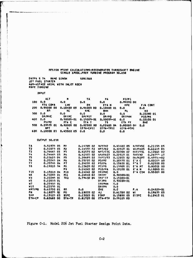
OFSrr.N POINT CALCULATIONS-PECFNERATEO TURBOSHAFT ENGINE SINGLE SPOOL.FREF TURBINE PROGRAM 30,036
0ATF9 5 7* NAME SINGH $091968 JFT FUEL STARTER ♦69-4STAGE AXIAL MITH INLET RECV FRFP TURBINE
INPUT
100
200
300
400
900
600
ALT M TA PA P2/P1 0.0 0.0 0.0 0.0 0.990O0 00
ETA COMB LHV EM ETA N HPE F/A CONT 0.95000 00 0.18*00 OS 0.96000 00 0.10000 01 0.0 0.0
BO nc BMC BMM »L MA 0.0 0.0 0.0 0.0 0.0 0.22260 01
OP/PMC OP/PC OP/PIT OP/PO OP/PHM P10/PA 0.0 0.50000-01 0.15000-01 0,5000o-oi 0.0 0.10100 01
P3/P2 FTA C FTA T T5 FTA PT EHE 0.2R970 01 O.ROOOO 00 0.82500 00 0*22600 04 0.80000 00 0.0
NPT N IFTA-CPM IFTA-TPIt (ETA-PTPI 0.10000 03 0.43500 05 0.0 0.0 0.0
OUTPUT 30.038
TA 0.5l87n 03 P» 0.14700 02 N/RTH2 0.43S0C 05 N/RTH5C 0.21150 05 T2 0.51870 03 P2 0.14550 02 MPT/02 0.22510 01 MIJ/0605 0.61610 03 T3 0.74440 03 PI 0.41570 02 NPT/T7C 0.5070D 02 0IIT/T5C 0.12860 02 T* 0.74441 03 P4 0.41570 02 WN/D6C7 0.22510 01 0MT/N2 0.287«" 07 T5 0.22600 0'. P5 0.39490 02 0HPT/T7 0.12850 02 0»t/N2PT 0.49«591.i- •02 T6 0.20740 04 P6 0.25230 02 P3/P2 0.28570 01 E"A C O.OOCCO 00 T7 0.20740 04 P7 0.24850 02 P5/P6 0.15650 01. F-A T 0.82500 00 T8 0.19010 04 PO 0.15620 02 P7/P8 0.15900 01 E"A PT 0.800CO 00
P9 0.14840 02 P10/PA 0.10100 01 E" A N 0.10000 01 T10 0.19010 04 P10 0.14840 02 OP/PHC 0.0 F"A COM 0.95000 00 MA 0.22280 01 Pll 0.14840 02 OP/PC 0.50000-01 M3 0.22280 01 TAU 0.79430 04 OP/"?T 0.15000-01 W5 0.22830 01 Or/PO C.5CC0O-01 M7 0.22830 01 fP/PHH 0.0 MIO 0.22030 01 DP/PN 0.0 MPT/P8 0.63700 01 80 0.0 EHE o.c F.A 0.24520- ■01 FN 0.18070 02 FG 0.18070 02 Aj 0.61700 02 Ml 0.19670 03 SHP 0.15120 03 BSFC 0.13010 01 FSHP 0.15850 03 EISFC 0.12410 01 ETA-CP 0.82680 00 ETA-TP 0.81720 00 ETA-PTP 0.79100 00
Figure C-l. Model 206 Jet Fuel Starter Design Point Data.
C-2
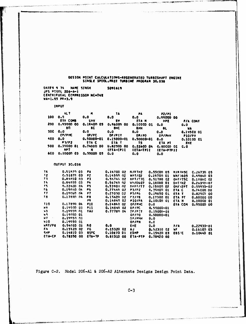
DESIGN POINT CAICUIATIPWS-P.EGENEP.ATED TUBBCSHAFT ENGINE SINGLE SPOOLtFREE TURBINE PP.OGP.AN 10.03«
0ATF9 9 74 NAME SINGH JF$ POOEt 206-A-1 CENTRIFUGAL CCKP8I5SOP NC-74« WA«1.9S P««3.9
S0916I9
INPUT
100
200
30C
400
500
6C0
M.T N TA PA P2/P1 0.0 0.0 0.0 0.0 0.99000 00
ETA CONS LHV en ETA N MPE E/A CONT 0.45000 00 0.1*400 OS 0.9600O 00 0.1C0C0 01 0.0 0.0
80 BC BMC BMH 8L HA 0.0 0.0 0.0 0.0 0.0 0.19SC0 01
CP/PMC OP/PC OP/PIT OP/PO OP/PHH P10/PA 0.0 0.50000-01 0.15000-01 0.50000-01 0.0 0.10100 Cl
P1/P2 ETA C ETA T T5 ETA PT EHE 0.39000 01 0.74000 00 0.82500 00 0.22*00 04 0.80COO CC CO
NPT N (ETA-CPU IETA-TPH IETA-PTPII 0.10000 03 0.55000 03 0.0 0.0 0.0
OUTPUT 30.038
T4 o.5i*7o 03 PA 0.14700 02 N/RTH2 0.55C00 05 N/PTH5C 0.26730 05 ri C.51870 03 P2 0.14550 02 WPT/02 0.19700 01 WN/ )605 0.4986D 03 T1 0.8485D 03 P3 0.54745 02 NPT/T7C 0.517BD 02 DHT/T5C 0.1886C 02 T4 0.84050 03 P4 0.56740 02 WN/0607 0.18080 01 DHT'N2 0.26390-07 T5 0.22600 04 P5 0.53900 02 0HPT/T7 0.15000 02 OH/42PT 0.55930-02 T6 0.19860 04 P6 0.27440 02 P3/P2 0.39000 01 ETA C 0.74C0O 00 T 7 0.I9C60 04 P7 0.27030 02 P5/P6 0.19650 OL ETA T 0.825CO 00 T8 0.17890 04 P8 0.15620 02 T7/P8 0.17300 01 ETA PT 0.80000 00
P9 0.14840 02 P10/PA 0.10100 01 ETA N 0.100CD 01 no 0.17890 04 PIO 0.14840 02 OP/PHC 0.0 ETA CON 0.95000 00 HA 0.19000 01 Pll 0.14840 02 OP/PC 0. 50000-01 W3 0.19590 01 TAU 0.77780 04 OP/P:T 0.15000-01 WS 0.19950 01 OP/PO 0.50000-01 HT 0.19950 01 OP/PHH 0.0 wio 0.19950 01 OP/PN O.C HRT/P8 0.54010 01 80 0.0 EHE 0.0 F/A 0.22930-01 FN 0.15320 02 PC 0.15320 02 AJ 0.52310 02 WF 0.16100 03 SMP 0.14810 03 BSFC 0.10870 01 ESHP 0.15420 03 E6S -C 0.10440 01 ETA-CP 0.78350 00 ETA-TP 0.81310 00 ETA-PTP 0.78920 00
Figure C-2. Model 206-A1 & 206-A2 Alternate Designs Design Point Data.
C-3
APPENDIX D
DERIVATIVE ENGINES
APPLICATIONS
Derivative engines, utilizing components from an existing design will decrease cost by increasing the production base. The basic Jet fuel starter design is readily adapted to thrust engine applications, both as a turbojet and a turbofan. The thrust class, 130 to 265 pounds, is suitable for Remotely Piloted Vehicles (RPV) propulsion.
TURBOJET DERIVATIVE
The turbojet derivative (Figure D-1A produces 130 pounds of thrust and weights only 40 pounds. The basic engine is 20 inches long, 10 inches in diameter and features a self-contained control system. The addition of a commercial electric starter and generator will increase the weight by 12 pounds for a total of 52 pounds.
The design uses the basic Jet fuel starter gas generator, consisting of the four-stage axial compressor, the combustor, and single-stage gas genera- tor turbine. A new combined front frame and air inlet housing are provided along with an integral rear frame, exhaust duct and Jet nozzle.
The fuel control is driven through a tower shaft by a face gear origin- ating from gas generator which in turn drives a low speed (2,000 rpm) ring gear concentric with the engine. This ring gear provides the drive for a 12- volt electric starter and generator. The starter and generator selected are currently in high production for outboard engines and ar^ readily available low cost units. The ring gear construction is similar to that used in the outboard engine industry except instead of a flywheel mount, it is carried by three grease-packed roller bearings. The front thrust bearing and gear drive system are po+ lubed and the rear bearing is lubricated by waste fuel supp- lied through the center of the gas generator shaft. The engine performance is summarized in Table D-l.
TURBOFAN DERIVATIVE
The turbofan derivative (Figure D-2) uses both the gas generator and low pressure turbine section from the Jet fuel rtarter. A front frame carries the gas generator thrust bearing, fan stator, shrouds, and the fan rotor and provides the support for the fan shaft thrust bearing. An exhaust duct «ind Jet nozzle provides the primary (hot stream) exhaust. A full length fan duct directs the fan flow to the rear and provi'des a separate fan nozzle. The accessory drive system is similiar to that discussed for turbojet derivative. The outboard engine starter and generator are utilized along with the low speed ring gear. The thrust bearings and face gear drives are pot lubed and
D-l
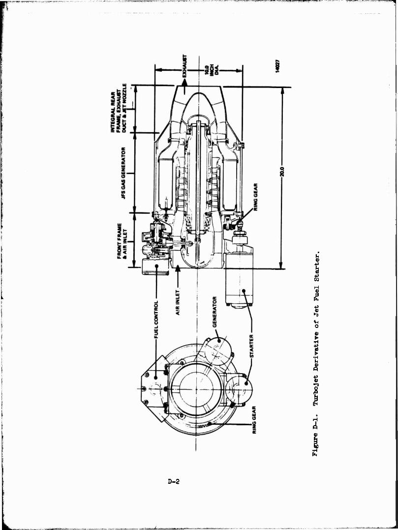
Si S H 0)
■P
o
t •H
I •H »H V p
t ""3
3
2
D-2
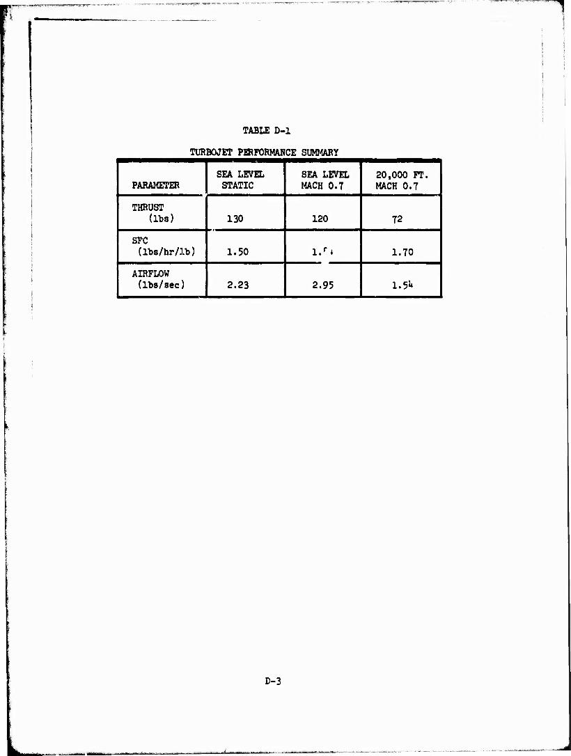
TABLE D-l
TURBOJET PERFORMANCE SUMMARY
PARAMETER SEA LEVEL STATIC
SEA LEVEL MACH 0.7
20,000 FT. MACH 0.7
THRUST (lbs) 130 120 72
SFC (lbs/hr/lb) 1.50 l.f + 1.70
AIRFLOW (lbs/sec) 2.23 2.95 1.51*
D-3
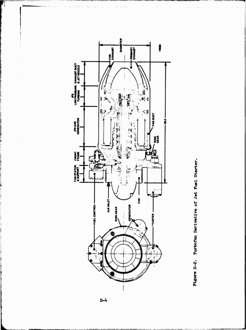
™™==1===E=
V
f s H
o
•H
I •H
5
eg l
P
D-l»
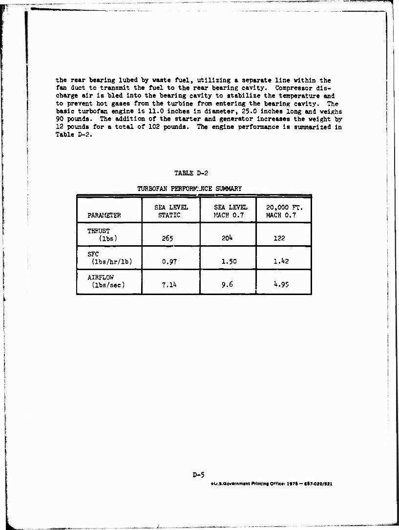
the rear bearing lubed by waste fuel, utilizing a separate line within the fan duct to transmit the fuel to the rear bearing cavity. Compressor dis- charge air is bled into the bearing cavity to stabilize the temperature and to prevent hot gases from the turbine from entering the bearing cavity. The basic turbofan engine is 11.0 inches in diameter, 25.0 inches long and weighs 90 pounds. The addition of the starter and generator increases the weight by 12 pounds for a total of 102 pounds. The engine performance is summarized in Table D-2.
TABLE D-2
TURBOFAN PERFORK'JICE SUMMARY
PARAMETER SEA LEVEL STATIC
SEA LEVEL MACH 0.7
20,000 FT. MACH 0.T
THRUST (lbs) 265 20U 122
SFC (lbs/hr/lb) 0.97 1.50 1.1*2
AIRFLOW (lbs/sec) 7.1k 9.6 J*.95
D-5 ftU.S.Qov«rnm«nt Printing Off lets 1979 - 697-020/921