Embed Size (px)
Citation preview
AD-752 611
HISTORICAL'SUMMA RY- OF ACTIVITIES IN THEUC-FAA FOG CHAMBER
Don 0. Horni ng, e t al
Californ~ia University
i, i I
Prepared for:I
Federal Aviation Administration
August 1971
: i %
II I
DISTRIBUTED -BY:
National Technical Infomnation ServiceU. S. DEATETOF COMMERCE5285 Port Royal Road, Springfield Va. 22151
Report No. FAA-R.711.94
HISTORICAL SUMMARY OFACTIVITIES IN THE UC-FAA FOG CHAMBER
UNDER CONTRACT ARDS-434
Don 0. HerniuP•.U. FHick
University of CaliforniaInstitute if Transportation anid Traffic Eugiueirinl
Richmond Field StationBerkeley, California 94884
[ofTU.S. International Transportation ExpositionI
Dulles Internctlonal Airport"Washington, D.C.0
5 ~May 27-June 4, 1972
AUGUST 1911 ; 19
FINAL REPORT
Availability is unlimited. Document may bereleased to the National Technical InformationService, Springfield, Virginia 22151, for sale
• to the public. Reproducedby
NATIONAL TECHNICAL•~nA. "INFORMATION SERVICEPI5UIIU US Dopor"ni.nt of CommercePrepard forsprin'afiXd VA 22151
DEPARTMENT OF TRANSPORTATIONFEDERAL AVIATION MINISTRATION
Systems Research & Development ServiceWashington, D.C. 20591
ACCESION t.
NTIS Stl$Doc luff 10t9in E"UNIN OU,-ED 0JUSTIFICATION .....................................
DISI1UTION/AVAILAMILIJY C011i~i-L:4. A.AIL L,f • . oi
nil
The contents of this report reflect the viewsof Institute of Transportation and TrafficEngineering, University of California, whichis responsible for the facts and the accuracyof the data presented herein. The contents donot necessarily reflect the official views orpolicy of the Department of Transportation.This report does not constitute a standard,specification, or regulation.
II
SIU
S... . _ ,1 .. . . . m••- '..
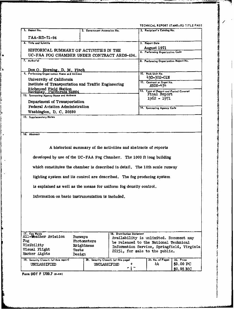
TECHNICAL REPORT STANDAkRD TITLE PAGE
1. Report No. 2. Government Acceaslon No. 3. Recipient's Catalog No.
rAA-RD-71-944. Title and Subtitle 5. Report Date
August 1971HISTORICAL SUMMARY OF ACTIVITIES IN THE 6. PerformAng Organization CodeUC-FAA FOG CHAMBER UNDER CONTRACT ARDS-434.
7. Authorls) 8. Performing Organization Report No.
Don 0. Hornigg- D. M. Finch9. Performing Organization Name and Address 10. Work Unit No.
University of California 430-302-01N11. Contract or Gro, t No.Institute of Transportation and Traffic Engineering 4.CatrGtN
Richmond Field Station 13. Typo of Report and Period CoveredSBerkeley- •afl rnia 94804 Fno Report 112. Sponsoring Agency Name and Address Fina Report1962 - 19711 Department of Transportation
Federal Aviation Administration 14. Sponsoring Agency Code .
Washington, D. C. 20590
15. Supplementary Notes
16. Abstract
A historical summary of the activities and abstracts of reports
developed by use of the UC-FAA Fog Chamber. The 1000 ft long building
which constitutes the chamber is described in detail. The 10th scale runway
lighting system and its control are described. The fog producing system
is explained as well as the means for uniform fog density control.
Information on basic instrumentation is included.
4
44
"17. K ey Words 18. Distribution Statement
All Weather Aviation Runways Availability is unlimited. Document mayFog Photometers be released to the National Technical
VisbiltyBrihtnssInformation Service, Springfieldj, VirginiaIVisual Flight Tests 22151, for sale to the public.M4arker Lights Design
19. Security Clessif. (of this report) 2D. Security Classif. (of this page) 21. No. of Pages 22. Price
UNCLASSIFIED UNCLASSIFIED 0 44 $3. 00 PC"I - $0.9 MC
Foirm DOT F 1700.7 te.69)
ACKNOWLEDGEMENTS
The extensive duration of the ARDS-434 contract has occasioned the employment of manypeople. The authors wish to thank all of the employees of the University who have contributedto the development and operation of the Fog Chamber. In particular, the following should be
mentioned:
Mr. Higino Paula Project EngineerMr. Ernie Curwen Research EngineerMr. Melvin McNabb Senior Maintenance ManMr. Karl Mellander Principal Electronic TechnicianMr. Jerry Jeffress Electronic TechnicianMr. Alvah Miller Assistant Development EngineerMr. Fred Collins ProgrammerMr. Jack Forster Sr Electronic TechnicianMr. Al Shaw Sr Electronic TechnicianMrs. Cless Fraser Sr Typist ClerkMrs. Mildred Mohr SecretaryMr. Gale Ahlborn Assistant Research EngineerMi•. Roger Muldavin Assistant Development EngineerMr. Arthur Alston Assistant Development EngineerMr. Donald K. Hamma Assistant Development EngineerMr. Richard Ciochon Sr Electronic TechnicianMr. Ben Wheeler Electronic TechnicianMr. Meyer Scharlack Sr Electronic TechnicianMr. Martin Ritchie Sr Coder
There have also been several Principal Investigators involved in various aspects of the FogChamber research. These are Professor H. E. Davis, Professor Dan M. Finch andProfessor R. Horonjeff. Professor Norman Kennedy, as Acting Director, Institute ofTransportation and Traffic Engineering, has been most helpful.
Throughout the efforts to produce essential research, the help of individuals and organizationshas been invaluable. Particularly the cooperation of various airline companies has beenappreciated in determining specifics concerning various aircraft. Among these are PanAmerican Airways, American Airlines, United Air Lines and Trans World Airlines. Airframe manufacturers have also been helpful. Among these were Boeing Aircraft and Lockheed.
Individuals who have contributed significantly to the success of various programs have been:
Capt. James Fleming Pan Am (Retired)Capt. William Ballinger Pan AmMr. Lou Wallick BoeingMr. William McGruder Lockheed
Various organizations have contributed the time of their members to achieve success in sometasks. Among these are Air Line Pilots Association and Air Port Operators Association.Throughout the life of the contract the assistance of several hundred pilots has been invaluablein evaluating the visibility conditions when "flying" the cockpit. To them go our thanks forsuffering through the discomforts and exigencies always inherent in an experimental setup suchas the Fog Chamber.
Preceding page blank - -
The FAA has been most helpful in providing technical assistance when needed. Many officialshave been involved deeply in the problems of the Fog Chamber and have contributed to thesolutions by their suggestions.
iv I
*1
111- - I
31
TABLE OF CONTENTS
Compendium of Work Performed, Including Abstracts of Reports .... 1
Amendments Listing .................................. 1
Reports .......................................... 4
Users of Fog Cbamber Other Than UC and FAA ................ 11
Test Facility ....................................... 13
Test Building ....................................... 13
Structural Information ............................. 13
Functional Features ............................... 14
Tramway System. .................................... 14
Structural Features ............................... 14
Functional Features ............................... 15
Fog Generating System ................................. 16
Control System ...................................... 17
Test-Light Circuits and Controls .......................... 18
*v i
1
'4 1
1
- V - -I
FINAL REPORT
HISTORICAL SUMMARY OFACTIVITIES IN THE UC-FAA FOG CHAMBER
UNDER CONTRACT ARDS-434
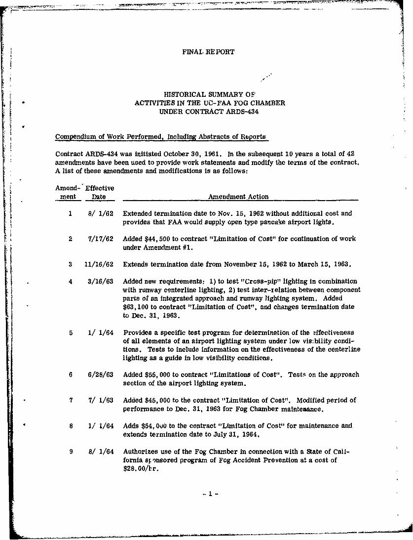
Compendium of Work Performed, Including Abstracts of Reports
Contract ARDS-434 was initiated October 30, 1961. In the subsequent 10 years a total of 42amendments have been used to provide work statements and modify the terms of the contract.A list of these amendments and modifications is as follows:
Amend- Effectivement Date Amendment Action
1 8/ 1/62 Extended termination date to Nov. 15, 1962 without additional cost andprovides that FAA would supply open type pancake airport lights.
2 7/17/62 Added $44, 500 to contract "Limitation of Cost" for continuation of workunder Amendment #1.
S3 11/16/62 Extends termination date from November 15, 1962 to March 15, 1963.
4 3/16/63 Added new requirements: 1) to test "Cross-pip" lighting in combinationwith runway centerline lighting, 2) test inter-relation between componentparts of an integrated approach and runway lighting system. Added$63, 100 to contract "Limitation of Cost", and changes termination dateto Dec. 31, 1963.
5 1/ 1/64 Provides a specific test program for determination of the ýffectivenessof all elements of an airport lighting system under low vis;bility condi-tions. Tests to include information on the effectiveness of the centerlinelighting as a guide in low visibility conditions.
6 6/28/63 Added $55, 000 to contract "Limitations of Cost". Test5q on the approachsection of the airport lighting system.
7 7/ 1/63 Added $45, 000 to the contract "Limitation of Cost". Modified period ofperformance to Dec. 31, 1963 for Fog Chamber mainteaance.
8 1/ 1/64 Adds $54, 000 to the contract "Limitation of Cost" for maintenance andextends termination date to July 31, 1964.
9 8/ 1/64 Authorizes use of the Fog Chamber in connection with a State of Cali-fornia st ')nsored program of Fog Accident Prevention at a cost of$28. 00/ ,r.
-- 1 --.--
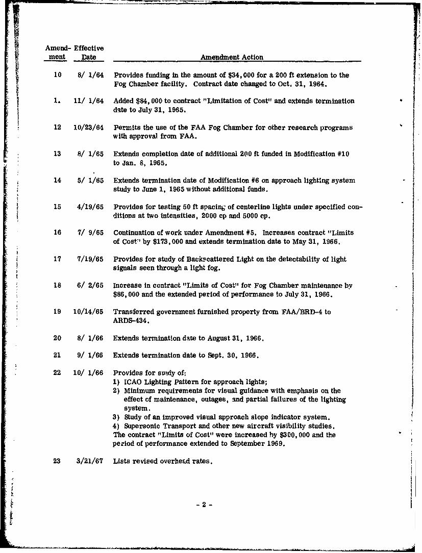
Amend- Effectivement Date Ameudment Action
10 8/ 1/64 Provides funding in the amount of $34, 000 for a 200 ft extension to theFog Chamber facility. Contract date changed to Oct. 31, 1964.
1, 11/ 1/64 Added $84, 000 to contract "Limitation of Cost'" and extends terminationi date to July 31, 1965.
12 10/23/64 Permits the use of the FAA Fog Chamber for other research programswith approval from FAA.
13 8/ 1/65 Extends completion date of additional 200 ft funded in Modification #10to Jan. 8, 1965.
14 5/ 1/65 Extends termination date of Modification #6 on approach lighting systemstudy to June 1, 1965 without additional funds.
15 4/19/65 Provides for testing 50 ft spacing of centerline lights under specified con-ditions at two intensities, 2000 cp and 5000 cp.
16 7/ 9/65 Continuation of work under Amendment #5. Increases contract "Limitsof Cost"' by $173,000 and extends termination date to May 31, 1966.
17 7/19/65 Provides for study of Back-scattered Light on the detectability of lightsignals seen through a light fog.
18 6/ 2/65 Increase in contract "Limits of Cost" for Fog Chamber maintenance by$86,000 and the extended period of performance to July 31, 1966.
19 10/14/65 Transferred government furnished property from FAA/BRD-4 toARDS-434.
20 8/ 1/66 Extends termination date to August 31, 1966.
21 9/ 1/66 Extends termination date to Sept. 30, 1966.
22 10/ 1/66 Provides for stidy of:1) ICAO Lighting Pattern for approach lights;2) Minimum requirements for visual guidance with emphasis on the
effect of maintenance, outages, and partial failures of the lightingsystem.
3) Study of an improved visual approach slope indicator system.4) Supersonic Transport and other new aircraft visibility studies.The contract "Limits of Cost" were increased by $300, 000 and theperiod of performance extended to September 1969.
23 3/21/67 Lists revised overhead rates.
"-2
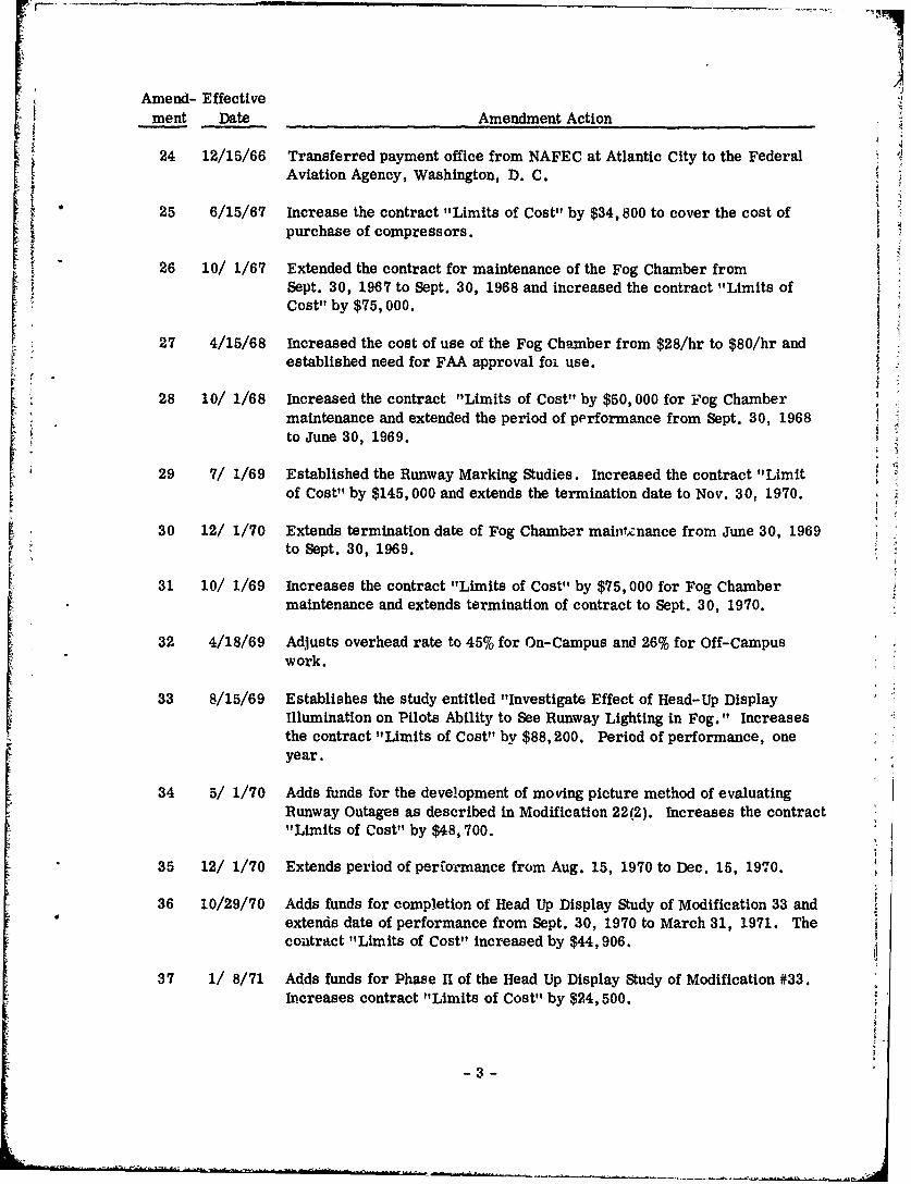
Amend- EffectiveA ment Date Amendment Action
* 24 12/15/66 Transferred payment office from NAFEC at Atlantic City to the FederalAviation Agency, Washington, D. C.
25 6/15/67 Increase the contract "Limits of Cost" by $34,800 to cover the cost ofpurchase of compressors.
26 10/ 1/67 Extended the contract for maintenance of the Fog Chamber fromSept. 30, 1967 to Sept. 30, 1968 and increased the contract "Limits ofCost" by $75, 000.
27 4/15/68 Increased the cost of use of the Fog Chamber from $28/hr to $80/hr andestablished need for FAA approval foi use.
28 10/ 1/68 Increased the contract "Limits of Cost" by $50, 000 for Fog Chambermaintenance and extended the period of performance from Sept. 30, 1968to June 30, 1969.
29 7/ 1/69 Established the Runway Marking Studies. Increased the contract "Limitof Cost" by $145,000 and extends the termination date to Nov. 30, 1970.
30 12/ 1/70 Extends termination date of Fog Chamber mainftznance from June 30, 1969to Sept. 30, 1969.
31 10/ 1/69 Increases the contract "Limits of Cost" by $75, 000 for Fog Chambermaintenance and extends termination of contract to Sept. 30, 1970.
32 4/18/69 Adjusts overhead rate to 45% for On-Campus and 26% for Off-Campuswork.
33 8/15/69 Establishes the study entitled "Investigate Effect of Head-Up DisplayIllumination on Pilots Ability to See Runway Lighting in Fog." Increasesthe contract "Limits of Cost" by $88,200. Period of performance, oneyear.
34 5/ 1/70 Adds funds for the development of moving picture method of evaluatingRunway Outages as described in Modification 22(2). Increases the contract"Limits of Cost" by $48,700.
35 12/ 1/70 Extends period of perio-mance from Aug. 15, 1970 to Dec. 15, 1970.
36 10/29/70 Adds funds for completion of Head Up Display Study of Modification 33 andextends date of performance from Sept. 30, 1970 to March 31, 1971. Thecouitract "Limits of Cost" increased by $44,906.
37 1/ 8/71 Adds funds for Phase IT of the Head Up Display Study of Modification #33.In.creases contract "Limits of Cost" by $24,500.
-3 -
Amend- Effectivement Date Amendment Action
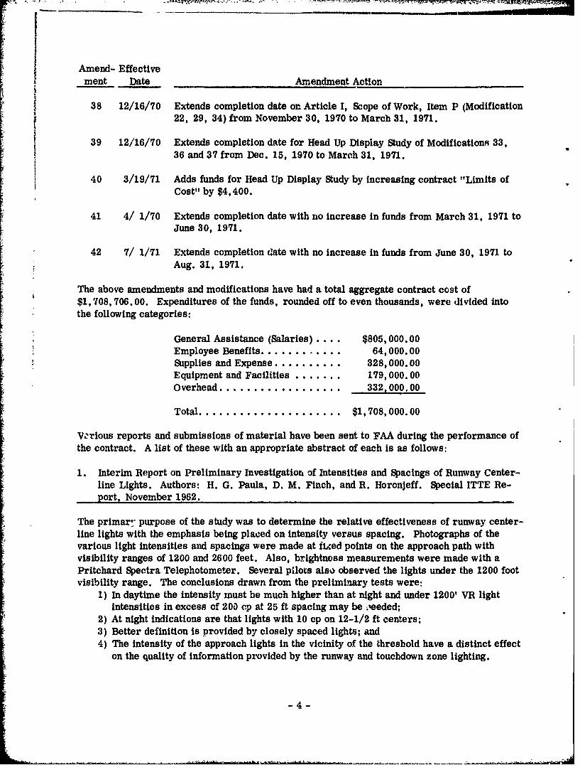
38 12/16/70 Extends completion date on Article I, Scope of Work, Item P (Modification22, 29, 34) from November 30, 1970 to March 31, 1971.
39 12/16/70 Extends completion date for Head Up Display Study of Modifications 33,36 and 37 from Dec. 15, 1970 to March 31, 1971.
40 3/19/71 Adds funds for Head Up Display Study by increasing contract "Limits ofCost" by $4,400.
41 4/ 1/70 Extends completion date with no increase in funds from March 31, 1971 toJune 30, 1971.
42 7/ 1/71 Extends completion date with no increase in funds from June 30, 1971 toAug. 31, 1971.
The above amendments and modifications have had a total aggregate contract cost of$1,708, 706.00. Expenditures of the funds, rounded off to even thousands, were divided intothe following categories:
General Assistance (Salaries) .... $805,000.00Employee Benefits ............ 64,000.00SSupplies and Expense .......... 328,000.00Equipment and Facilities ....... 179,000.00Overhead .................... 332,000,00
Total ....................... $1,708,000.00
V.2rious reports and submissions of material have been sent to FAA during the performance ofthe contract. A list of these with an appropriate abstract of each is as follows:
1. Interim Report on Preliminary Investigation of Intensities and Spacings of Runway Center-line Lights. Authors: H. G. Paula, D. M. Finch, and R. Horonjeff. Special ITTE Re-port, November 1962.
The primar,- purpose of the study was to determine the relative effectiveness of runway center-line lights with the emphasis being placed on intensity versus spacing. Photographs of thevarious light intensities and spacings were made at ficed points on the approach path withvisibility ranges of 1200 and 2600 feet. Also, brightness measurements were made with aPritchard Spectra Telephotometer. Several pilots also observed the lights under the 1200 footvisibility range. The conclusions drawn from the preliminary tests were:
1) In daytime the intensity must be much higher than at night and under 1200' VR lightintensities in excess of 200 cp at 25 ft spacing may be oeeded;
2) At night indications are that lights with 10 cp on 12-1/2 ft centers;3) Better definition is provided by closely spaced lights; and4) The intensity of the approach lights in the vicinity of the threshold have a distinct effect
on the quality of information provided by the runway and touchdown zone lighting.
-4-
2. Interim Report No. 2, An Investigation of Three Combinations of Intensities and Spacingsof the U. S. National Standard for Runway Touchdown Zone and Centerline Lighting.Authors: H. G. Paula, G. Ahlborn, W. E. Gillfillan, R. Horonjeff and D. M. Finch.Special ITTE Report. May 1963.
This was a continuation of the initial study of centerline light intensity and spacing require-ments. 16 pilots participated b. ýne evaluation. Brightness distribution graphs were plottedfor all conditions studied. Three conditions, or light patterns, were used in 1200 ft visualrange. The conclusions reached were:
1) That the highest apparent intensity of touchdown zone and centerline lighting war nothigh enough for daylight fog in 1200 ft visibility range in bright sunshine; and
2) In all cases, both day and night, prior to reaching the threshold, the centerline lightsdid not stand out as clearly as the touchdown zone lights. Additional tests at muchhigher light intensities were recommended.
3. Interim Report No. 3. A Comparative Evaluation of 3:3:3, 3:2:1, and 7:3:1 Patterns ofRunway Touchdown Zone Lighting at Different Intensities and Spacings. Author:H. G. Paula. Special ITTE Report. July 1963.
In the 3:2:1 pattern, the light barrettes constituting the narrow gage were made up of 3 lightsfor the first 1000 ft after threshold, 2 lights for the second 1000 ft and one light for the third1000 ft. The intensities were 7500 cp at 100 ft for the touchdown zone and 200 cp at 25 ft forthe centerline for the high, 200 cp at 25 ft for the touchdown zone and 60 cp at 25 ft for thecenterline for the low, and a combination of 7500 cp at 100 ft for the first 1000 ft of the touch-down zone after threshold and 900 cp for the second and third 1000 ft with 200 cp at 25 ft forthe centerline. The 7:3:1 pattern consisted of lights spaced 25 ft apart acro.S the runway withthe center three lights spaced 12-1/2 ft apart longitudinally along the runway. The seven lightsystem extended for 1500 ft from the threshold, the three center lights extended for the- econd1500 ft, and the centerline lights extended for avother 1000 ft. All lights were set for 10 cp.This configuration was only evaluated at night in light fogs. The 3:3:3 pattern consists of3 lights placed 30 ft from the centerline spaced every 100 ft. The latter by concensus of15 pilots was preferred for both daytime and nighttime visibility ranges of 2600 ft and 1200 ft.The intensity for daylight use, even at 7500 cp, was considered too low for good guidance. Thelow intensity was unacceptable under most conditions.
4. Interim Report No. 4. A Preliminr. y Evaluation of Effectiveness of Runway Marking inFog with Bright Sunshine Overhead. Authors: D. M. Finch and R. Horonjeff. SpecialITTE Report. August 1963.
The use of lights as a means of providing runway position in bright sunlight conditions islimited. In this study, all-weather runway marking as required by FAA Technical StandardOrder N106, dated Oct. 5, 1960, was painted on the runway in the Fog Chamber and observa-tions by a small number of pilots were made in daytime fog with bright sunshine overhead.The conclusions reached were that si , runway markings were of considerable aid to thepilots for landings and takeoffs and wtlj superior to lights alone. The combination of touch..down zone and centerline lights and marking was an improvement over markings alone, but toobtain the maximum benefit from the systam, the effective intensity of the centerline lights,as well as the threshold, must be increased.
-5-
5. Interim Report No. 5. An Investigation of Intensities for the U. S. National Standard Run-way Touchdown Zone and Centerline Lighting in a Visual Range of 1200 Feet. Authors:
D. M. Finch, R. Horonjeff, H. G. Paula, and G. Ahlborn. Special ITTE Report.January 1964.
This report contains the results of an investigation in the Fog Chamber concerned primarilywith the establishment of the intensities in a visual range of 1200 ft of the runway touchdown
[ zone and runway centerline lights for the spacing and configuration specified in AGA-NS13, the
"U. S. National Standard for Runway Touchdown Zone Lighting and Runway Centerline Systems."I In addition, a brief evaluation of the inner 1000 ft of approach lights was conducted.
The intensities were evaluated primarily by the pilots observing the lights, measurements ofbrightness, and analysis of photographs. A total of 36 transport pilots from the majordomestic and international carriers, the Flight Standards Service of the Federal AviatioiAgency, and the U. S. Air Force participated in the tests. The tests were conducted duringthe day and night.
Findings considered significant are:1) During the day, background brightness has a profound influence on required intensity.
The higher the background brightness, the higher must be the intensity to provide
adequate guidance.
2) When the background brightness is high, the gains in range that can be achieved, even
by a large increase in intensity, are relatively small (although there is a significantimprovement in the clarity of lights). Background brightness is therefore an importantparameter in the design of a lighting system.
3) For conditions as provided in the Fog Chamber in this test program, centerline lightsshould be at a minimum of 2000 cp at 25-ft spacing along the full length of the runwayand the touchdown zone lights should be at a minimum of 7500 cp at 100-ft spacing.
4) The distribution of intensity from each lighting fixture is extremely important. Theintensity (candlepower) viewed by the pilot should be approximately equal for all lightswithin his field of view. This is not realized if a fixture has too narrow a distributionin either the vertical or horizontal planes. The genmetry of the pilot's field of view issuch that a fixture should provide a uniform intensity through an angle extending to13-15 degrees above horizontal. This is especially important in dense fog because thepilot must depend for guidance primarily on the lights near the aircraft.
5) Visual guidance provided by runway touchdown zone and centerline lights can be im-proved with the photometric distribution suggested in thi_ r3port. The feasibility ofaccomplishing this in the field should be investigated.
6) For threshold lights, it is suggested that the intensity be increased to provide no lessthan 5000 cp in green light and that the intensity be distributed as suggested in thisreport.
7) Modification of the inner 1000 ft of approach lights as described in this report was con-sidered desirable by the pilot observers, especially during the day. The modificationconsists of placing an additional white-light barrette midway between the threshold andthe red-light terminating bar and making the inner 4-light segment of the terminatingbar white instead of red.
-6 -
6. Evaluation of Runway Lighting Systems for Effectiveness in Dense Fog. Authors:D. M. Finch, R. Horonjeff and H. G. Paula. Special ITTE Report. January 1966.SRDS Report No. 65-58.
The test facilities and methods are described, the test results are presented, and some of the
influencing factors, such as background brightness and cockpit cutoff angle, are discussed. Inaddition, a number of recommendations are made with regard to intensities and photometricdistributions for runway lights, and with respect to changes in the present U.S. standardapproach light system.
Evaluations were made with pilot observers, photometric measurements and photographictechniques.
Tests of runway lighting systems in dense fog show that an intensity of 200 to 300 cp, now ingeneral use for centerline lights at U. S. airports, is not high enough for effective guidance ina fog density of 1200-ft visual range, day or night. These tests also indicate that in daytime,with a 1200-ft visual range, runway marking is considerably useful to pilots as a supplementto runway lighting. In addition, on the basis of pilots? reactions, the present U.S. standardpattern (3:3:3) for touchdown-zone and centerline lights was found to be more effective thaneither of two other patterns (3:2:1 and 7:3:1) evaluated. Pilots also preferred a modified ver-sion of the present U. S. standard approach-light system.
7. Evaluation of ICAO Visual Aid Panel Approach Lighting Patterns. Authors: D. M. Finch,R. Horonjeff, and H. G. Paula. Special ITTE Report. February 1966. FAA Report No.RD-65-104.
Nine different patterns for the last 1000 feet of approach lights before runway threshold, in-cluding two European and seven U. S. configurations, were evaluated on a reduced scale in theFog Chamber by tests in daytime and nighttime fog (1200-ft visual range). The tests consistedof observations by 12 pilots. While some of the approach light patterns served better thanothers, none was clearly outstanding. Therefore, no clear choice could be made for overalleffectiveness. Certain features seem desirable in an approach light pattern. These are:
1) A well defined centerline without excessive number of lights;2) Distinctive and easily identified marker lights at the 1000 ft and 500 ft distance before
threshold;3) No lighting elements so close to the threshold that they tend to visually break up the
continuity of the green threshold lights, and4) As simple a configuration of lights as possible.
8. Photometric Detection Contrast of Airport Lighting in Decreased Visibility. Authors:D. M. Finch, R. Horonjeff, and H. G. Paula. Special ITTE Report. August 1966.FAA Report No. RD-66-46.
A photometric method is described for determining the visibility of airport runway lights undervarious conditions of visual range and background brightness. The method is based on measure-ment of a defined quantity, Cd, called photometer detection contrast, and depends on the cor-relation of this quantity with subjective visibility. Use of the photometric method isillustrated by tests conducted in the FAA Fog Chamber. Values of Cd were calculated fromluminance scans of runway lights in daytime and nighttime visual ranges of 1600, 1200, and
-7-
800 ft. Maximum visibility distances for the lights were then determined by assuming a trialvalue of .05 as the minimum usable Cd for subjective visibilitý under the various fog conditions.An automatic scanner mechanism u~ed with a telephotometer for the efficient acquisition of theluminance data is also described.
The photometric method of detecting contrast .has the following advantages:
1) Provides a means of collecting test data that is nmuch more efficient and economicalthan the use of pilot observers;
2) The objective data so, collected does not display the vagaries often encountered insubjective determbtations;
3) The photometrir data, once obtained, remain useful for making runway lighting evalu4-tions even thr.dgh subsequent work requires changes in the criteria for effebtiveness.
9. Effect of Landing-Light Backscatter on Target Visibility in Fog. Authors: D. M. Finch,E. C. Curwen, and L. E. King. Special ITTE Repor. September 1966. FAA Report,No. RD-66-60.
Tests were conducted in the FAA Fog Chamber to determine if backscatter from aircraft land-Ing lights in visual ranges of 3 miles, 2600 ft and 1200 ft would interfdre with an observer'sability to see a set of amber target lights at the runway threshold. Results from a total of518 test observations made by 14 observers indicate substantially no reduction in target-lightvisibility in visual ranges of 3 miles and 2600 ft. In the 1200 ft visual range, the visibility ofthe target lights was reduced by an appreciable amount.
10. Effect of Backscatter from Aircraft Beacon Lights on Target Visibility in Fog. SpecialITTE Report. November 1966. FAA Report No. RD-66-57._
'tests were performed in the. FAA Fog Chamber to determine how thý backscatter fr6m air-craft beacon lights (collision-avoidance lights) in a fog of 0.21 per mile transmittance affectsan observer's ability to see a set of target lights at a fixed distance equal to the corresponding,visual range of 3 miles (approximately 16,000 ft). The tests investigated three white andthree red beacon lights, both steady-burning and flashing, with peak intensities from 1900 to200,000 cp in white and 1200 to 25, 000 cp in red. Results from" a total of over. 10,000 observa-tions, made by 34 observers, show that use of the beacon lights produced no appreciable re-duction in target-light visibility except with the highest white-light intensity. There was noapparent difference between the steady-burniing'and flashing modes of the beacons insofar astarget visibility is concerned.
11. Photometer Detection Contrast and Visibility of Runway Lighting in Dense Fog. Authors:D. M. Finch, R. Horonjeff, H. G. Paula. Special ITT.E Report. June 1967. FAAReport No. RD-67-33.
Using a previously developed but modified photometric method, the visibility of a runwaylighting system was studied under various conditions -of visual range and backgound brightness.The method is based on measurement of a defined. quantity, Cd,t called photometer detectioncontrast, and depends on the correlation of this quantity with subjective visibility. All testswere performed in the FAA Fog Chamber at 1/10 scale. Photometric data for the runwaylights were obtained in daytime and nighttime visual ranges of 1200, 900, and 700 ft, andmaximum visibility distances for various portions of the lighting system were then determined
-8-
on the basis of an assumed value of .06 for the minimum usable Cd. Based on the number oflighting elements that would be visible to a pilot under the various test conditions studied, itwas concluded that the lighting system would become but marginally effective for visual guid-ance in a daytime fog of 900 ft visual range and background brightness of about 5M0-600 fL. Thesame would hold true fr the nighttime fog of 700 ft visual range. In a daytime visual raage of700 ft, the system would no longer provide effective visual guidance.
12. Evaluation of Centerline Lighting Indications for Runway-Distance Remaining and TaxiwayExits. Authors: D. M. Finch, R. Horonjeff, and K. Mellander. Special ITTE Report.June 1967. FAA Report No. RD-67-10.
Tests were conducted in the FAA Fog Chamber to determine the effectiveness of coloredcenterline lights for indicating runway-distance remaining and for marking high-speed taxiwayexits (large-radius turnoffs) under daytime and nighttime visibility conditions down to 700 ft ofvisual range. The tests consisted of observations by pilots of various lighting patterns undersimulated rollout conditions. The results of the tests indicate that red centerline lights can beeffectively used for indicating runway-distance remaining, either in combination with whitelights or alone, if the intensity of the red lights is high enough to provide adequate guidanceunder reduced visibility. The test results also indicate that under conditions of 700 ft visualrange, adequate identification and guidance for large-radius taxiway turnoffs can be providedby steady-burning green lights along the taxiway centerlines, with a pattern having an equiva-lent intensity at least that of 1000 cp lights at 12.5 ft spacing in daytime and 500 cp at 12.5 ftat night. Steady-burning taxiway lights were preferred by the pilots over flashing lights by avery wide margin. Taxiway centerline lights having a much wider beam than that specified bythe FAA were visible from a point on the runway centerline farther beyond the beginning of thetaxiway turnoff than were the specified narrower-beam lights.
13. An Optical System for Improved Vi,?ual Approach Slope Indicators (VASI). Authors:
D. M. Finch and R. .ruldavin. tSubmitted in Draft form December 1968.)
The following is an abstract of this unpublished report:
A study of means for improving the performance of existing Visual Approach Slopp. Indicators(VASI) shows that an optical system using an elliptical reflector, a red-white interfecencefilter and a suitable projection lens would provide considerably higher efficiency and a sharpercolor transition in the light beam. Tests indicate that such an optical system is feasible foruse in a VASI unit and permits the design of a unit that would provide satisfactory performanceunder various environmental conditions.
14. Runway Marking Studies. Authors: Don 0. Horning and K. Mellander. FAA Report No.RD-70-27. August 1970.
To help evaluate the effectiveness Uf several different runway marking patterns under limitedvisibility conditions, a set of special composite photographs was prepared simulating a pilot's-eye view of the patterns from various points along the glide path. The set includes three mark-ing patterns (the U. S. Standard, TSO-N10b, and two modified versions thereof) on bothasphalt and concrete surfaces, as viewed under daytime visual-range conditions from 2400 ftdown to 700 ft. Each of the composite photos consisted of two visual components combinedthrough appropriate processing techniques. One component was made by photographing a 30:1
-9-

scale model runway layout in the UC- FAA Fog Chamber unde-r a given set of conditions. Theother component was taken from motion picture film showing the inside of a Boeing 707 flightsimulator cockpit as viewed from the pilot's-eye position. The contrasts in the original sceneswere matched in the photographs by means of suitable photometric controls.
i 15. Head Up Display Study. Authors: Don 0. Horning, D. M. Finch, Karl Mellander andAlvah Miller. Special ITTE Report. Submitted for approval June 1971.
The objective of this study was to develop methods for the objective and subjective evaluationof the Head Up Display concept under low visibility conditions.
To effect this, two separate studies were made: An objective stdy of the physical parametersassociated with the runway lighting system and a representative head up display device. Theseparameters Included transmission reflectance and luminances on the HUDisplay device andluminances of the cockpit interior as well as the external scene. The measurements weremade with a Pritchard Telephotometer mounted to scan the entire scene at a 30 minutes of arcinterval. Certain limited segments were scanned at a 6 minute interval.
The data from these scans were impressed on magnetic tape and analyzed by computer tech-niques. The printout revealed areas of high brightness. These were examined in detail forglare sources and the entire scene analyzed for the accommodation level which could be ex-pected by the pilot viewing the same scene.
The conclusions to be drawn from these studies were that under normal operating conditionswith the visibility range at 1200 ft day or night, no glare sources were identified and theaccommodation levels were reasonable. The combining glass of the representative HUDisplayused did not materially affect the values. Some diminution of glare was experienced, as mightbe expected by the partially silvered mirror.
The subjective tests were performed by mounting a typical Head Up Display device, the Singer-Librascope L-193, in the cockpit of the "flying" tramway of the Fog Chamber and subjectingexperienced pilots to making approaches under limited visibility conditions. Instrumentationprovided .data on at what point in the approach the pilot was sufficiently well oriented to makethe decision to land. Identical runs were made 1) with the pilot using the Head Up Mosplay, and2) following the present mode when making an instrument approach to have the pilot concen-trating on the cockpit instrument display and coming head up when the co-pilot signalled he hadlights in view. The first series of these runs indicated a slight improvement in pilot per-formance using the HUDisplay. However, the sample was small and certain refinements ininstrumentation were required to improve the accuracy of the data. A second series of pilotsproduced more constitent data with the results showing virtually no difference between head upand head down decision points.
All pilots were asked to comment on the experiment and their opinion of the head up concept.The pilots agreed almost unanimously that the experiment as a whole was very adequate inproviding them with a high degree of realism, particularly at night for the visibility conditionsused, and that the Head Up Display concept had validity in providing them with a sense ofconfidence in making a decision to land under adverse weather conditions.
The original objectives to develop methods for evaluating the Head Up Display concept, bothobjectively and subjectively, were successfully met.
- 10-

71-
16. Development of Filming Technique for Runway Lighting Studies. Authors: D. K. Hamma,D. M. Finch. Special ITTE Report. (Submitted to FAA for Comment on Aug. 1, 1971.)
This report delincvtes the various techniques developed on this project to provide a motion pic-ture of a simulated approach, touchdown, and rollcut under various conditions, day and night,on centerline, offset, and crabbed, in low visibility conditions of 1200 and 700 ft fogs. Themethod utilizes a compositing of films made in a 707 cockpit training simulator and films madein the FAA Fog Chamber. The result is a simulated moving picture of the flight. The realismis fairly good. Some improvement can be ex'pected as lighting systems used to ohotograph thecockpit are improved and special techniques are employed to provide realistic transition fromwholly instrument flight to the externai scene. A step by step procedure is outlined in orderthat the technique can be employed by other agencies.
In addition to the above reports, several films of the last segment of the approach, touchdown,and rollout of an aircraft in simulated low visibility conditions have been produced. A 16 mmversion entitled "Fog Visibility Study, Series In" has been made available to airlines as atraining aid. To date 30 copies have been sold and 4 copies have been given to governmental
Sagencies and air,3raft manufacturers.
In May 1971 a 35 mm film consisting of 12 composited scenes showing a pilot's view of the
landing sequence as though he were flying a 707 aircraft was delivered to FAA. This filmincludes several approaches with the approach system lights and the runway lights depictingvarious percentages of outage. The purpose of the film is to permit FAA to display this filmto a large number of airline pilots, FAA personnel and airport operators and determine fromtheir reaction the upper limit of random outage that can be permitted on an approach and run-way lighting system. The film can also be used as an orientation aid for pilots to familiarizethem with what to expect to see when landing under reduced visibility conditions.
Over the period of years since the completion of the Fog Chamber, many governmentalagencies and companies have made use of the unique features of the Fog Chamber for studiesin low visibility. A partial list of these is as follows:
1. Joint Venture, Belgian Airport and Airways Agency and Atellers de ConstructionElectriques de Charleroi. Reported in FAA RD-67-32, "Final Report Tests on ACECVideometer in Fog Chamber at UC Berkeley, USA." Under project No. 430-302-01N.Feb. 1967.
2. Sylvania Electric Products, Inc. Evaluation of Gated Luminaires in Fog. July 1968.
3. Texas Instrument Co. Evaluation of Forward Looking Infrared System for U S Air Force.January 1967.
4. Automobile Manufacturers Association. Determination of the Efficacy of Red, Green,and Amber as suitable colors for Automotive Rear Lighting in Low Visibility Conditions.April 1966.
5. Einac Division of Varian. Human Eye Response to Low Intensity Navigation Lights forSpace Craft Rendevous and Docking Maneuvers. April 1967.
6. Bendix Corporation, Navigation & Control Division. Fog Simulator Program. UnderFAA contract FA 67WA-1770. Nov. 1967.
7. Panama Canal Zone. Development of Variable Intensity Navigational Lights for Sectionsof the Panama Canal. 1968-69.
8. California Division of Highways. Fog Accident Prevention Study. 1965.
9. Santa Barbara Research Center. Study of Active and Passive Infra Red DetectionSystems. Dec. 1969.
10. Mercedes-Benz of North America. Static and Dynamic Evaluation of Mercedes-BenzTurn Signal to Headlamp Spacing Relationehip. Static tests run in Fog Chamber underlow visibility conditions. Nov. 1969.
11. Golden Gate Bridge Authority. Evaluation of Center Line Lights for Automotive Guidancein Low Visibility Conditions. 1965.
12. Division of Bay Toll Crossings. Evaluation of Continuous Bridge Lighting Under LowVisibility Conditions. July 1971.
13. Air Force, Department of Defense. Study of I.1 Air Force Security Devices. April
1969.
14. American Airlines. Sonic Fog Dispersal Study. 1969.
15. General Precision-Singer Corporation. High Intensity Infra Red Source as a Fog Dis-sipator and Fog Penetration by 3x1O6 cp Light Source. May 1970.
16. California Highway Patrol. Evaluation of Reflex Reflectors Under Low Visibility Condi-tions. Feb. 1968.
17. Department of Transportation, National Highway Safety Bureau. Contract No.FH-11-6549, Glare and Driver Vision. Aug-Sept. 1968.
Any funds derived from these activities for the use of the Fog Chamber have been credited tothe ARDS-434 account. Staff support was charged directly to these programs and reduced thestaff costs for the FAA contract. FAA has benefitted from most of these programs indirectly
or directly by1) additional knowledge acquired by the staff on low visibility problems, and2) reports from contracting agencies supplied to FAA.
In the nine year period encompassing the ARDS-434 contract, over 1200 individuals havesigned the guest roster. The preponderance of these people have been directly associatedwith some phase of aviation activity. Represe-.tatives of aviation activity or interest from21 foreign countries are included in the group. Several newscasts utilizing the Fog Chamberactivity have been broadcast locally and on nationally syndicated programs.
- 12-
I
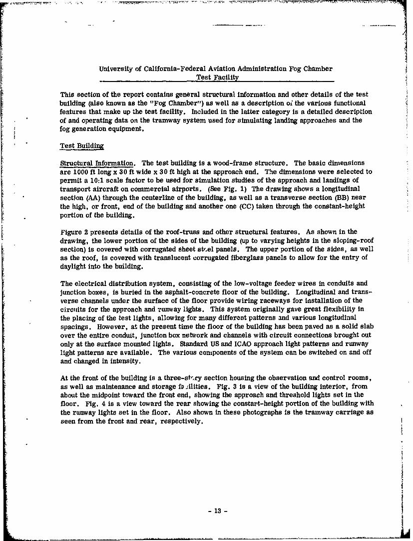
University of California-Federal Aviation Administration Fog ChamberTest Facility
This section of the report contains general structural information and other details of the testbuilding (also known as the "Fog Chamber") as well as a description o; the various functionalfeatures that make up the test facility. Included in the latter category is a detailed descriptionof and operating data on the tramway system used for simulating landing approaches and thefog generation equipment.
Test Building
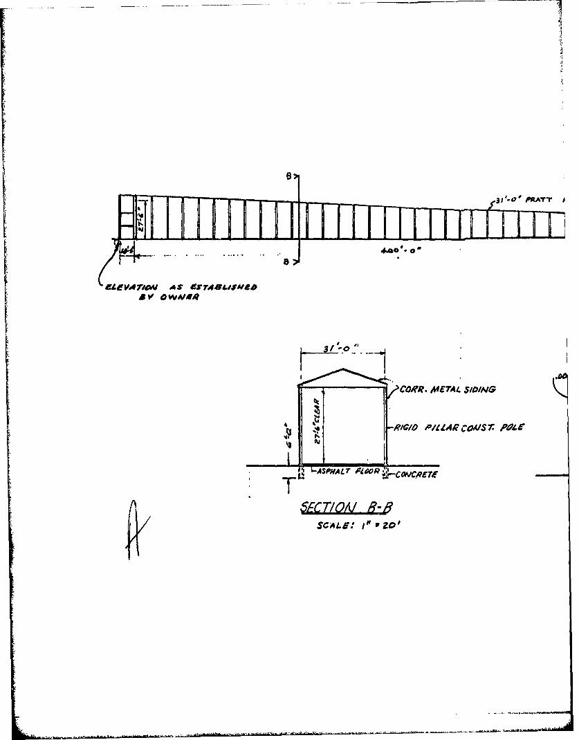
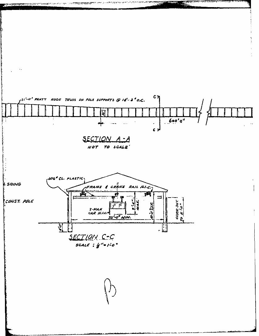
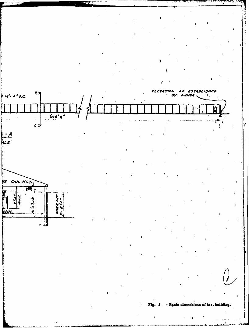
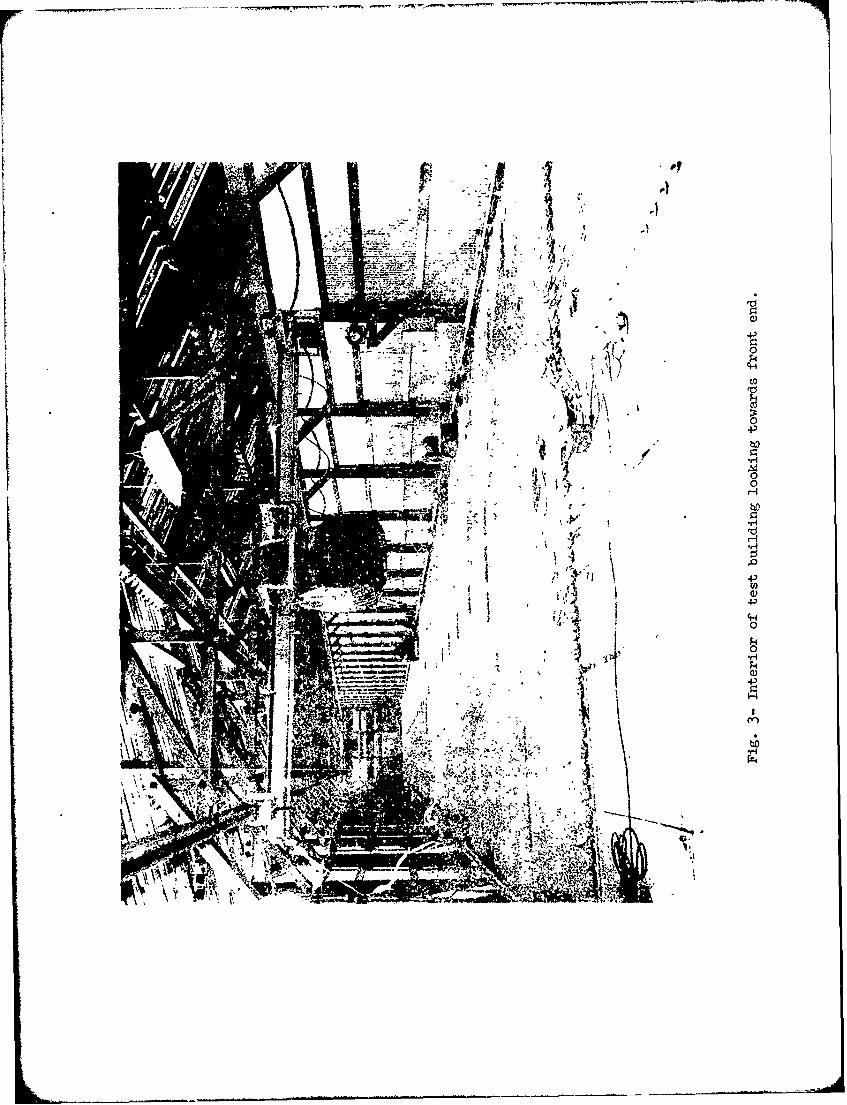
Structural Information. The test building is a wood-frame structure. The basic dimensionsare 1000 ft long x 30 ft wide x 30 ft high at the approach end. The dimensions were selected topermit a 10:1 scale factor to be used for simulation studies of the approach and landings oftransport aircraft on commercial airports. (See Fig. 1) The dcawing shows a longitudinalsection (AA) through the centerline of the building, as well as a transverse section (BB) nearthe high, or front, end of the building and another one (CC) taken through the constant-heightportion of the building.
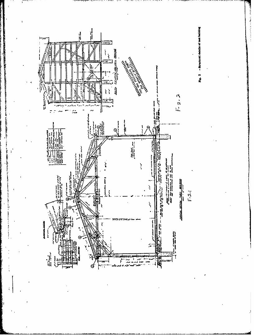
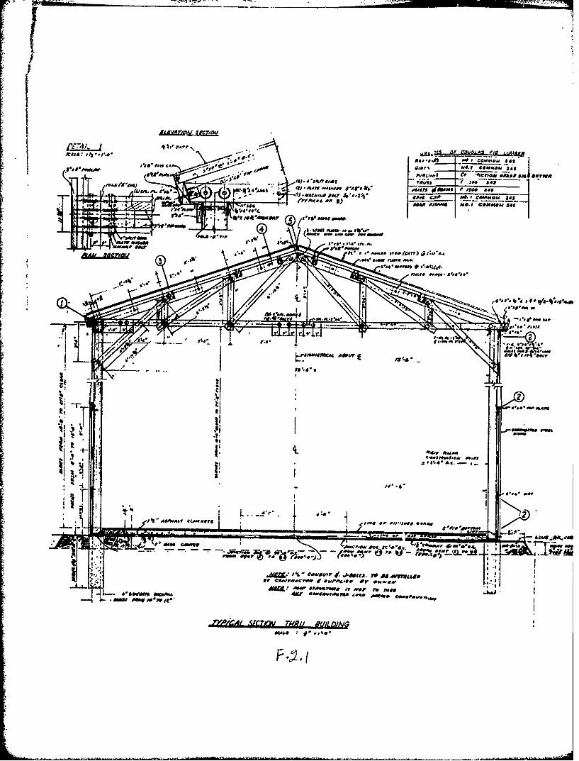
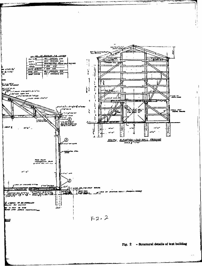
Figure 2 presents details of the roof-truss and other structural features. As shown in thedrawing, the lower portion of the sides of the building (up to varying heights in the sloping-roofsection) is covered with corrugated sheet stf.el panels. The upper portion of the sides, as wellas the roof, is covered with translucent corrugated fiberglass panels to allow for the entry ofdaylight into the building.
The electrical distribution system, consisting of the low-voltage feeder wires in conduits andjunction boxes, is buried in the asphalt-concrete floor of the building. Longitudinal and trans-verse channels under the surface of the floor provide wiring raceways for installation of thecircuits for the approach and runway lights. This system originally gave great flexibility inthe placing of the test lights, allowing for many different patterns and various longitudinalspacings. However, at the present time the floor of the building has been paved as a solid slabover the entire conduit, junction box network and channels with circuit connections brought outonly at the surface mounted lights. Standard US and ICAO approach light patterns and runwaylight patterns are available. The various components of the system can be switched on and offand changed in intensity.
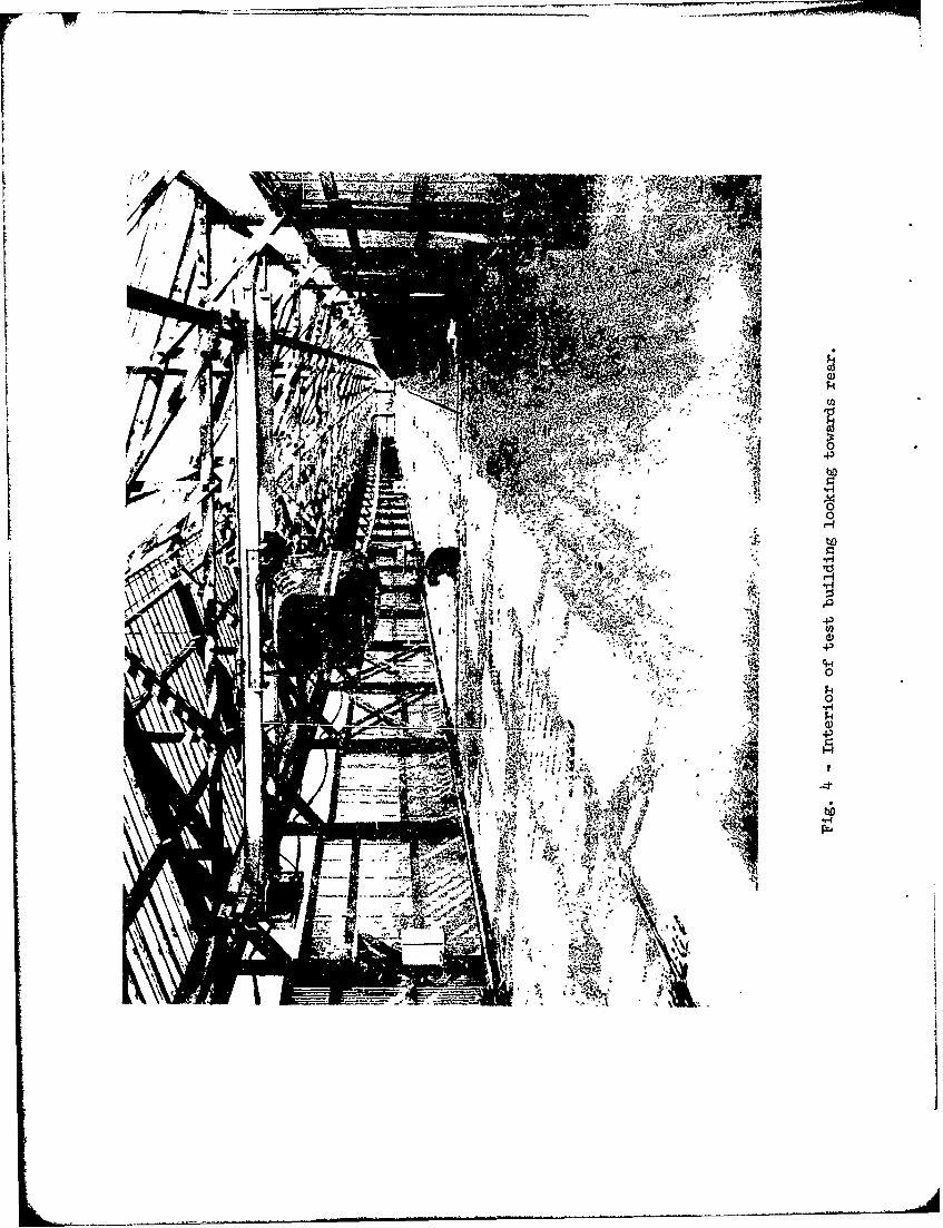
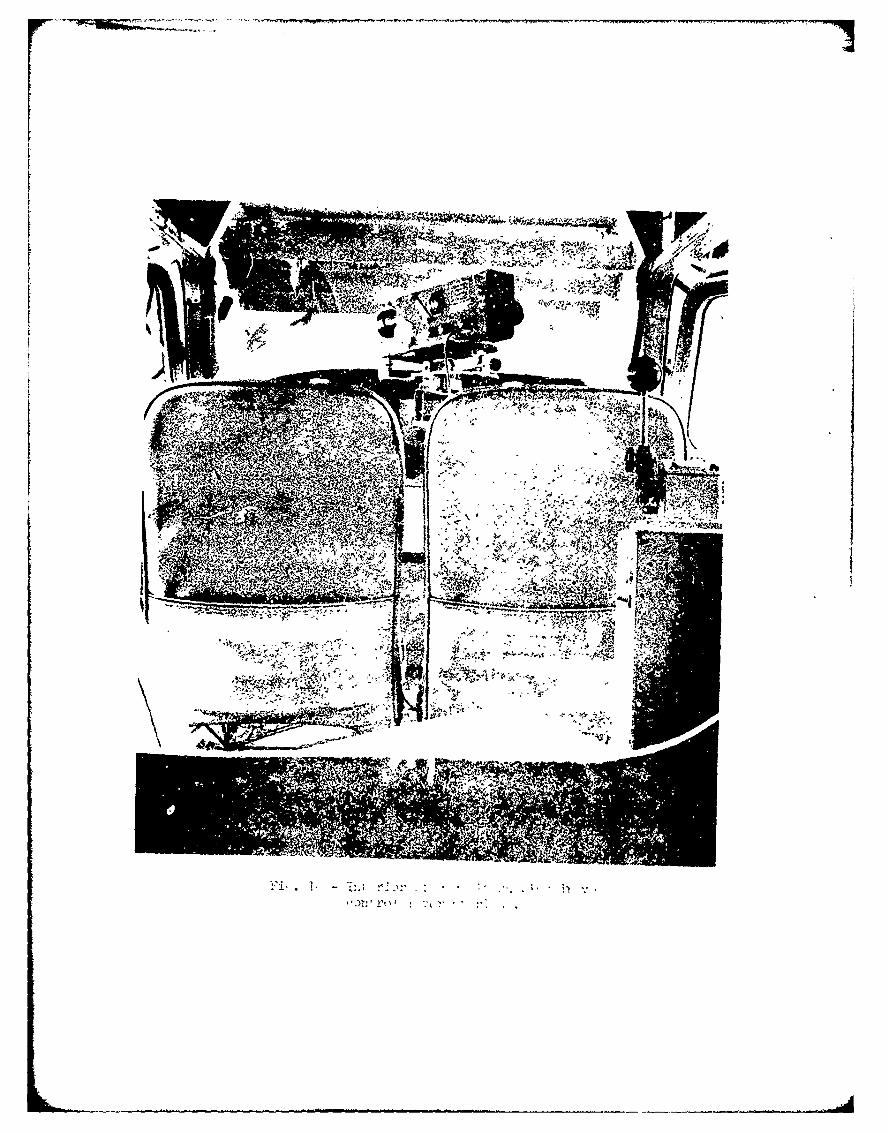
At the front of the building is a three-strkry section housing the observation and control rooms,as well as maintenance and storage fo Alities. Fig. 3 is a view of the building interior, fromabout the midpoint toward the front end, showing the approach and threshold lights set in thefloor. Fig. 4 is a view toward the rear showing the constart-height portion of the building withthe runway lights set in the floor. Also shown in these photographs Is the tramway carriage asseen from the front and rear, respectively.
-13 -
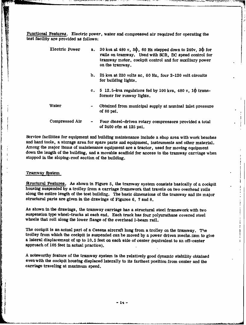
Functional Features. Electric power, water and compressed air required for operating the
test facility are provided as follows:
Electric Power a. 30 kva at 480 v, 34, 60 Hz stepped down to 240v, 3) for[ rails on tramway. Used with SCR, DC speed control fortramway motor, cockpit control and for auxiliary poweron the tramway.
b. 25 kva at 220 volts ac, 60 Hz, four 2-120 volt circuitsfor building lights.
c. 5 12.5-kva regulators fed by 100 kva, 480 v, 1) trans-former for runway lights.
Water - Obtained from municipal supply at nominal inlet pressureof 80 psi.
Compressed Air Four diesel-driven rotary compressors provided a totalof 2400 cfm at 125 psi.
Service facilities for equipment and building maintenance include a shop area with work benchesand hand tools, a storage area for spare parts and equipment, instruments and other material.Among the major items of maintenance equipment are a tractor, used for moving equipmentdown the length of the building, and a movable scaffold for access to the tramway carrtage whenstopped in the sloping-roof section of the building.
Tramway System
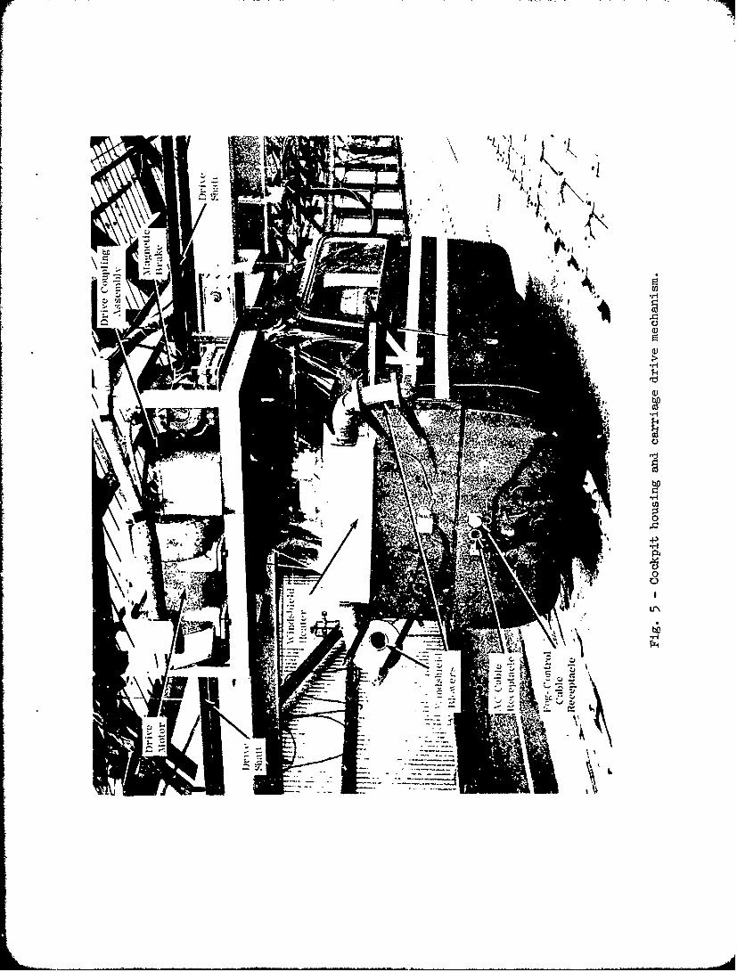
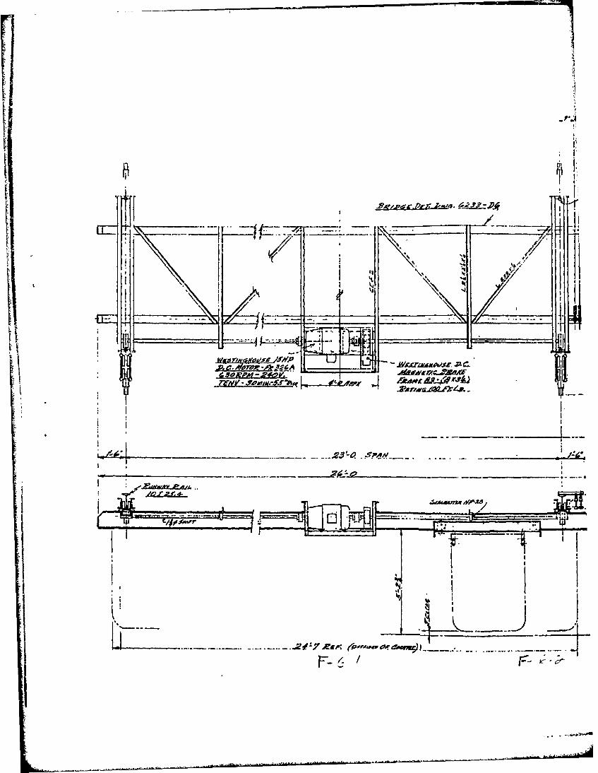
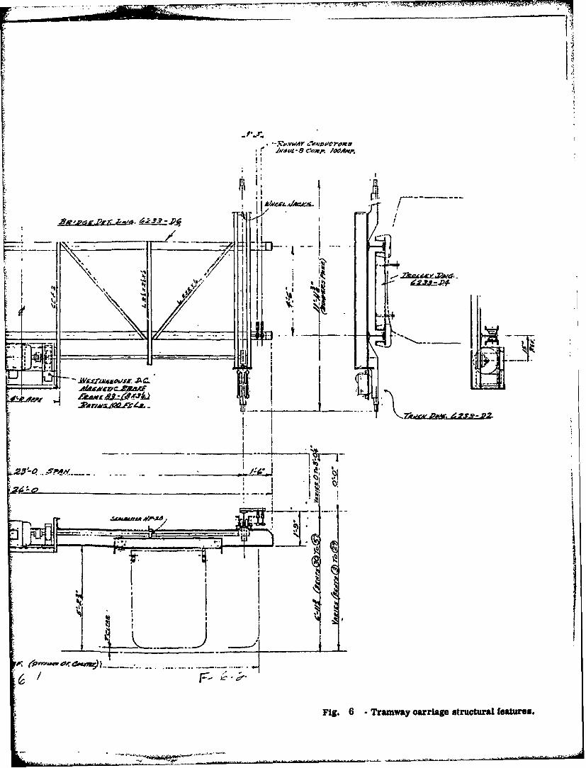
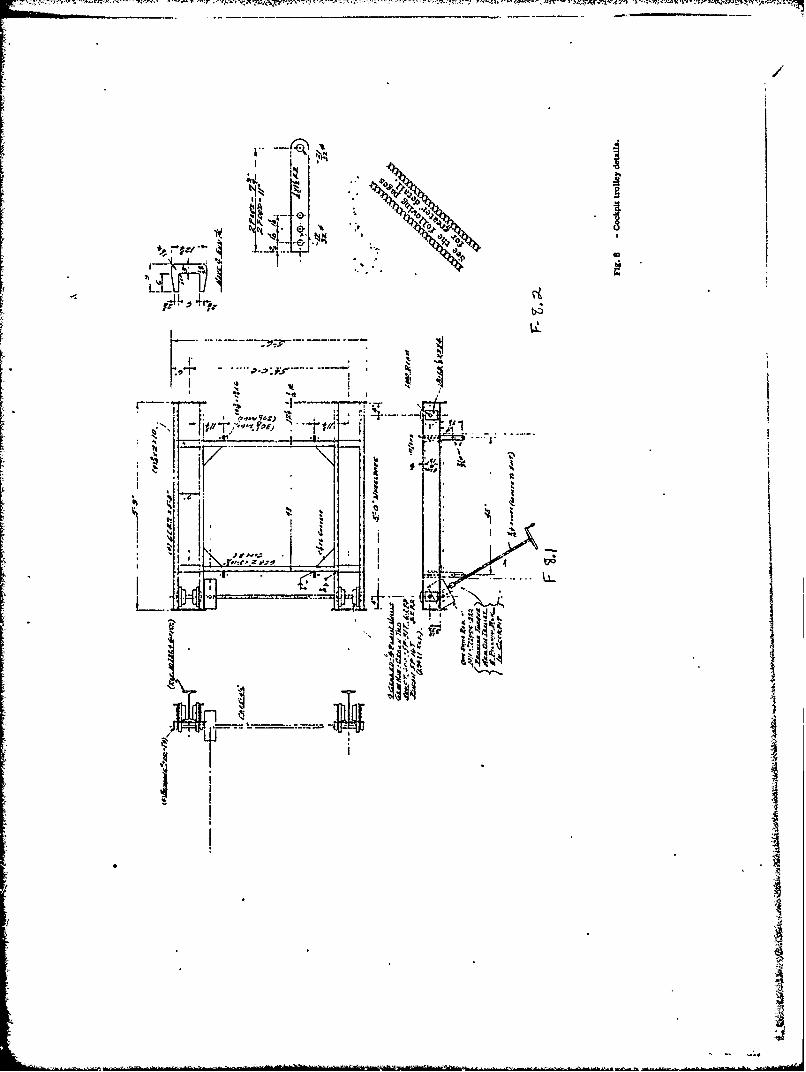
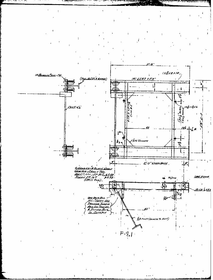
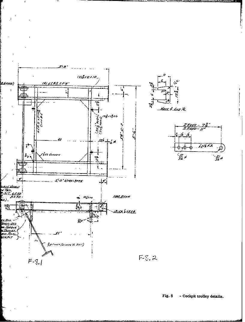
Structural Features. As shown in Figure 5, the tramway system consists basically of a cockpithousing suspended by a trolley from a carriage framework that travels on two overhead railsalong the entire length of the test building. The basic dimensions of the tramway and its majorstructural parts are given in the drawings of Figures 6. 7 and 8.
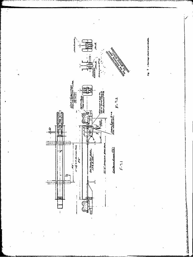
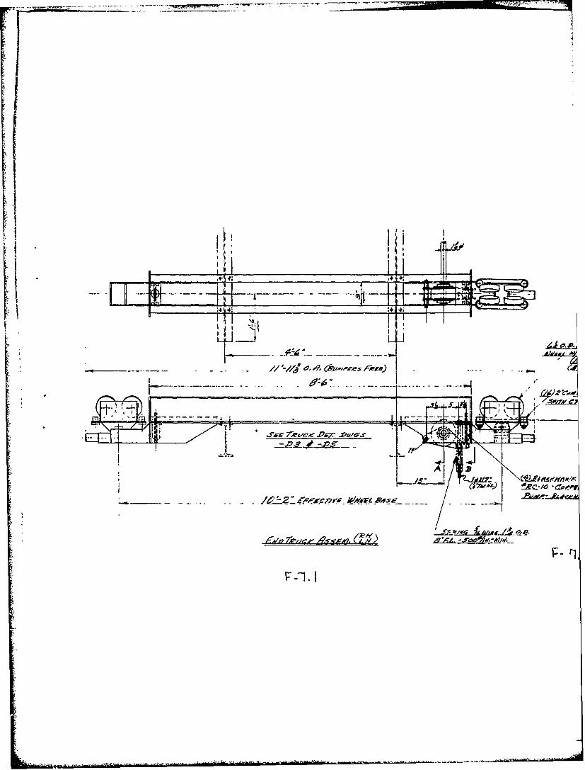
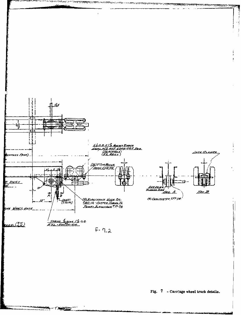
As shown in the drawings, the tramway carriage has a structural steel framework with twosuspension type wheel-trucks at each end. Each truck has four polyurathane covered steelwheels that roll along the lower flange of the overhead I-beam rail.
The cockpit is an actual part of a Cessna aircraft hung from a trolley on the tramway. Thetrolley from which the cockpit is suspended can be moved by a power driven mecha.ism to givea lateral displacement of up to 10.5 feet on each side of center (equivalent to an off-centerapproach of 105 feet in actual practice).
A noteworthy feature of the tramway system is the relatively good dynamic stability obtainedevenwith the cockpit housing displaced laterally to its farthest position from center and thecarriage traveling at maximum speed.
- Iii -
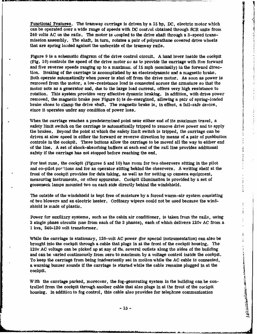
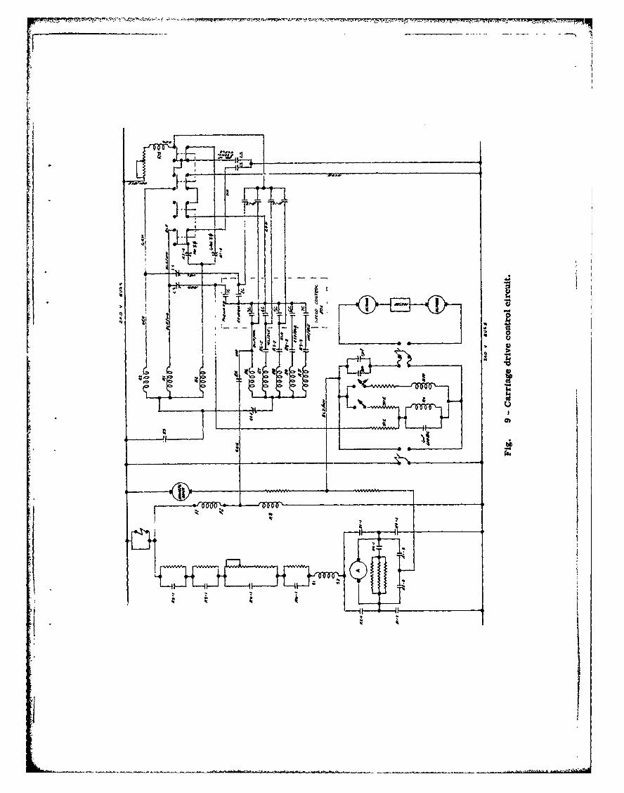
Functional Features. The tramway carriage is driven by a 15 hp, DC, electric motor whichcan be operated over a wide range of speeds with DC contmol obtained through SCR units from240 volts AC on the rails. The motor is uoupled to the drive shaft through a 3-speed trans-mission assembly. The shaft, in turn, rotates a pair of polyurathane covered drive wheelsthat are spring loaxded against the underside of the tramway rails.
Figure 9 is a schematic diagram of the drive control circuit. A hand lever inside the cockpit(Fig. 10) controls the speed of the drive motor so as to provide the carriage with five forwardand five reverse speeds ranging up to a maximun. of 15 mph (nominally) in the forward direc-tion. Braking of the carriage is accomplished by an electrodynamic and a rragnetic brake.Both operate automatically when power is shut off from the drive motor. As soon as power isremoved from the motor, a low-resistance load is connected across the armature so that themotor acts as a generator and, due to the large load current, offers very high resistance torotation. This system provides very effective dynamic braking. In addition, with drive powerremoved, the magnetic brake (see Figure 5) is de-energized, allowing a pair of spring-loadedbrake shoes to clamp the drive shaft. The magnetic brake is, in effect, a fail-safe device,since it operates under any condition of power loss.
When the carriage reaches a predetermined point near either end of its maximum travel, asafety limit switch on the carriage is automatically tripped to remove drive power and to applythe brakes. Beyond the point at which the safety limit switch is tripped, the carriage can bedriven at slow speed in either the forward or reverse direction by means of a pair of pushbuttoncontrols in the cockpit. These buttons allow the carriage to be moved all the way to either endof the line. A set of shock-absorbing buffers at each end of the rail line provides additionalsafety if the carriage has not stopped before reaching the end.
For test runs, the cockpit (Figures 5 and 10) has room for two observers sitting in the pilotand co-pilot poi-'tions and for an operator sitting behind the observers. A writing shelf at thefront of the cockpit provides for data taking, as well as for setting up camera equipment,measuring instruments, or other apparatus. Cockpit illumination is provided by a set ofgooseneck lamps mounted two on each side directly behind the windshield.
The outside of the windshield is kept free of moisture by a forced warm-air system consistingof two blowers and an electric heater. Ordinary wipers could not be used because the wind-shield is made of plastic.
Power for auxiliary systems, such as the cabin air conditioner, is taken from the rails, using3 single phase circuits (one from each of the 3 phases), each of which delivers 120v AC from a1 kva, 240-120 volt transformer.
While the carriage is stationary, 120-volt AC power (for special instrumentation) can also bebrought into the cockpit through a cable that plugs in at the front of the cockpit housing. The120v AC voltage can be picked up at any of thL several outlets along the sides of the buildingand can be varied continuously from zero to maximum by a voltage control inside the cockpit.To keep the carriage from being inadvertently set in motion while the AC cable is connected,a warning buzzer sounds if the carriage is started while the cable remains plugged in at thecockpit.
W ith the carriage parked, moreover, the fog-generating system in the building can be con-trolled from the cockpit through another cable that also plugs in at the front of the oockpithousing. In addition to fog control, this cable also provides for telephone communication
- 15 -
between the cockpit and the ccntrol room. When the carriage is in motion, communication be-tween cockpit and control room is carried on by means of an intercom system operating throughthe power buses.
To accommodate for the filming reported in "Development of Filnming Technique for Runway
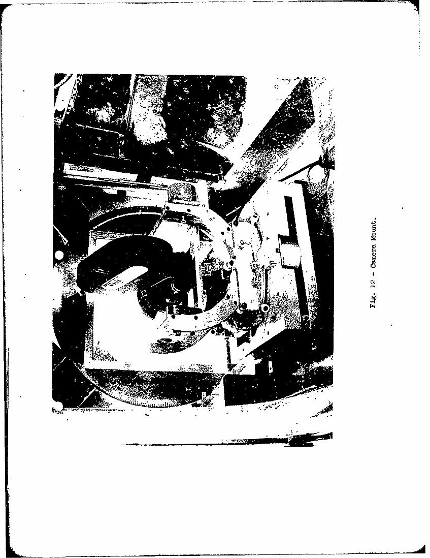
Lighting (Aug. 1971). "1 certain modifications were made to the cockpit. The front of the lowerportion of the cockpit was modified to provide a large window. Provision was made to bolt aspecial camera mount to the floor with the camera sighting through the window. To providethe necessary realism to the films, the external sceno must appear to pitch, roll, and yaw.The cockpit on the tramway is capable of longitudinal and lateral motion as well as yaw. How-ever, the yaw motion of the cockpit could not be used because from the pilot's view point or eyeposition the external scene moves relative to hiB eyes. Since the camera had to be mountedforward of the axis of rotation for yaw, a distorted view would be seen in the film; therefore,V-e yaw motion of the cockpit was not used and all pitch, roll and yaw were accomplished inthe camera mount with rotation taking place about the nodal point of the camera lens system.
Figure 12 shows the camera mount in the cockpit. The mount was bolted to the floor of thecockpit and adjusted to a height to represent the accepted pilot's eye height for the 707 aircraft.Mounted in front of the camera and forming the window through which the filming was done wasa double glass square. Each square could be rotated independently by synchronous steppingmotors. The glass in the windows was selectively given a ground glass finish In such a
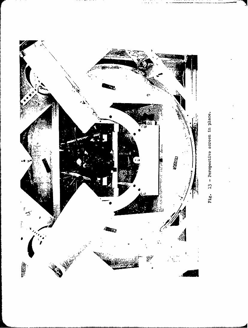
manner that In daylight the normal background brightness gave the appearance of fog. Byadjusting the rotation of these glass elements, the field of view of the camera was restrictedto an area closely approximating the perspective view of the runway at any given distance oraltitude. This successfully masked out the actual building structure from the film, but per-mitted the normal wide angle view of the lens. Hot air blower kept the windows from beingfogged by impact during a travelling filming sequence. Figure 13 shows the perspective screenin place. The selectively ground glass windows have been removed for purposes of taking thephotograph.
Fog Generating System
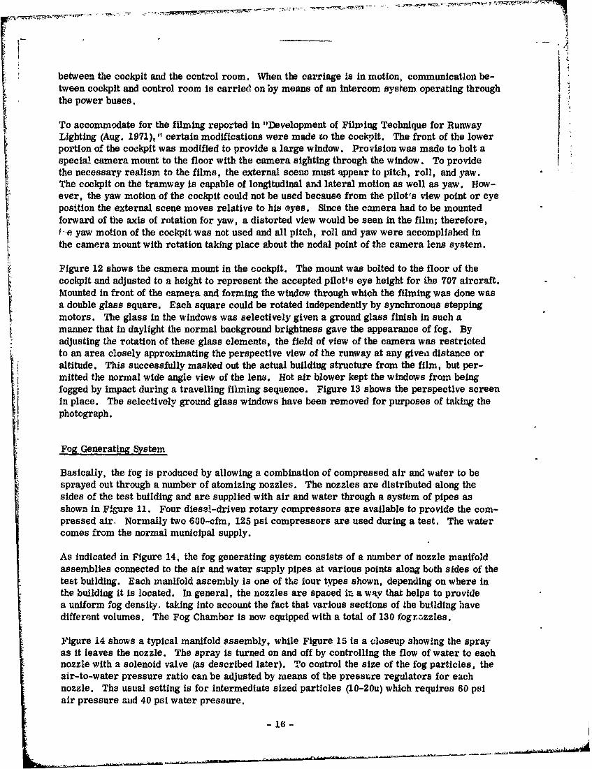
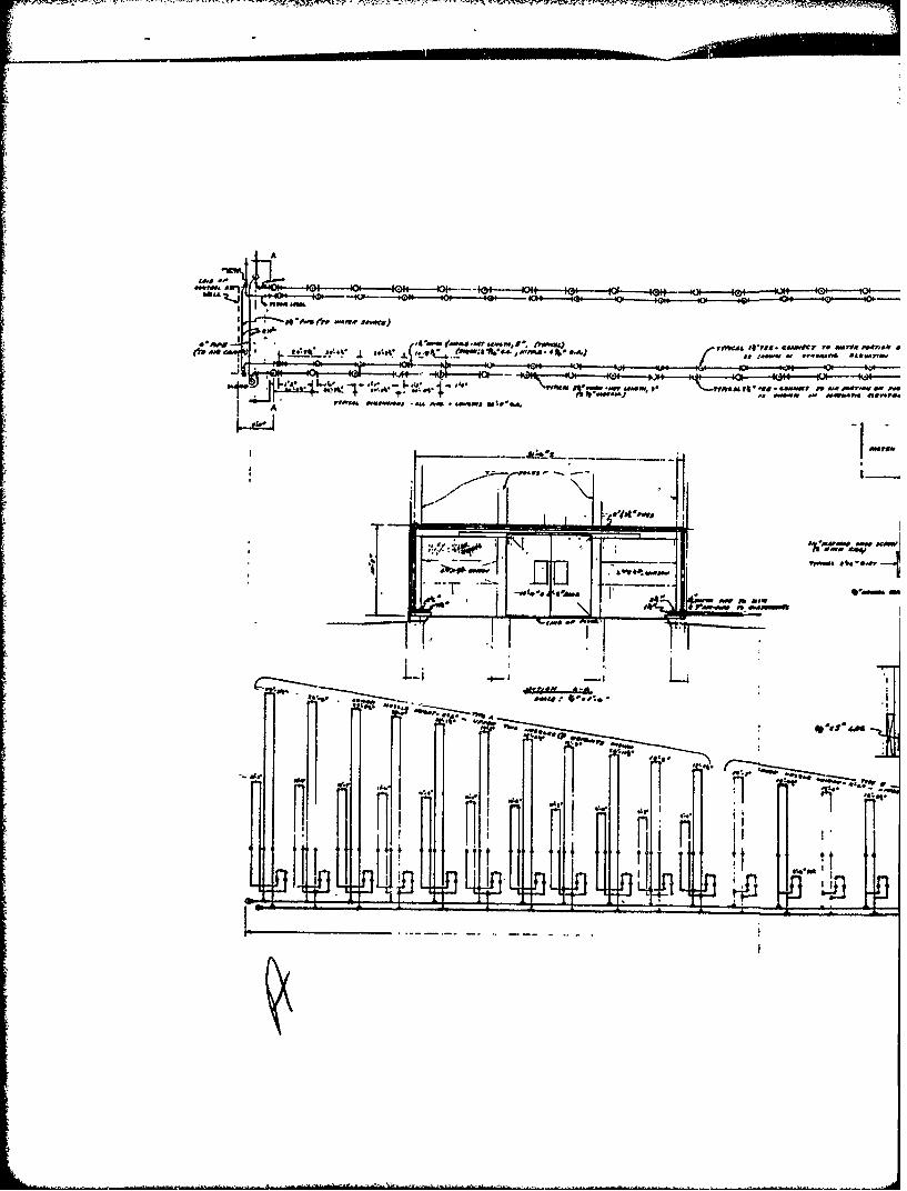
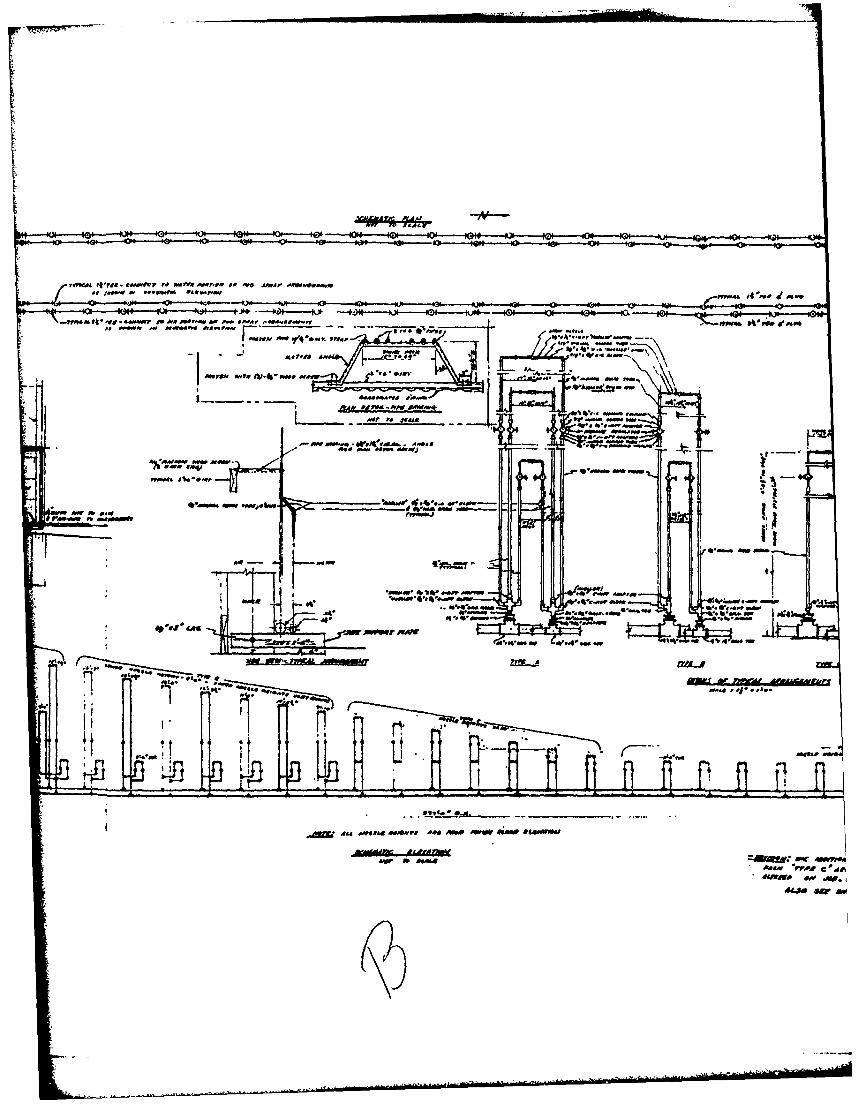
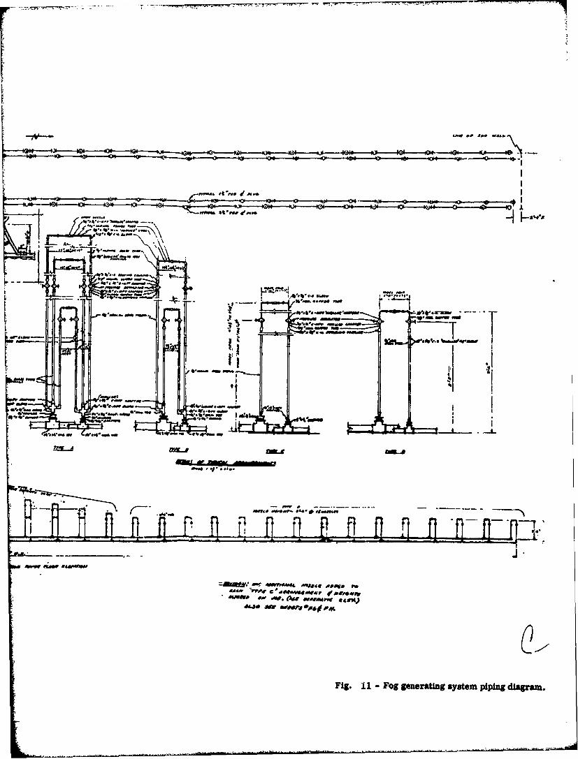
Basically, the fog is produced by allowing a combination of compressed air and water to besprayed out through a number of atomizing nozzles. The nozzles are distributed along thesides of the test building and are supplied with air and water through a system of pipes asshown in Figure 11. Four diese!-driven rotary compressors are available to provide the com-pressed air. Normally two 600-cfm, 125 psi compressors are used during a test. The watercomes from the normal municipal supply.
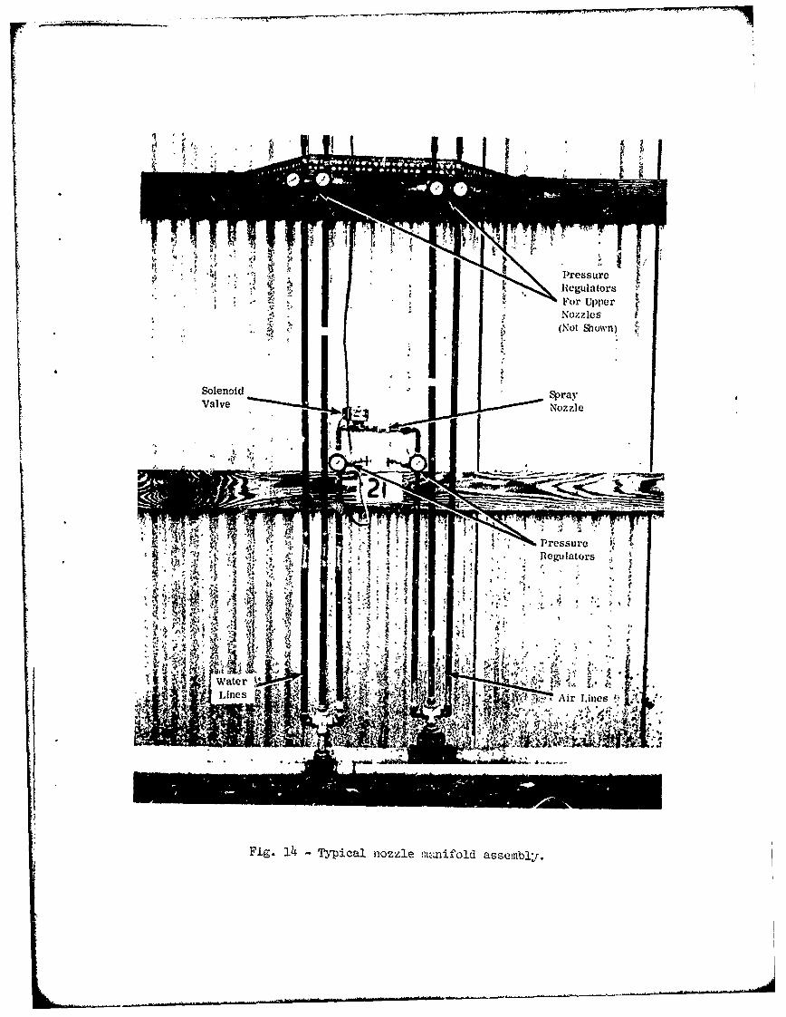
As indicated in Figure 14, the fog generating system consists of a number of nozzle manifoldassemblies connected to the air and water supply pipes at various points along both sides of thetest building. Each manifold aseembly is one of the four types shown, depending on where inthe building it is located. In general, the nozzles are spaced in a way that helps to providea uniform fog density. taking into account the fact that various sections of the building havedifferent volumes. The Fog Chamber is now equipped with a total of 130 foggr.,;zzles.
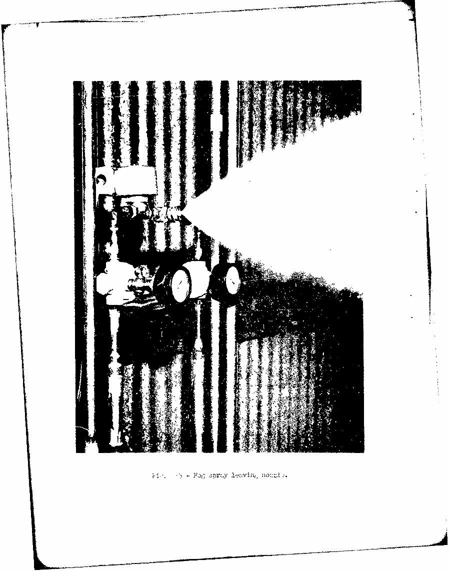
Figure 14 shows a typical manifold assembly, while Figure 15 is a Vloseup showing the sprayas it leaves the nozzle. The spray is turned on and off by controlling the flow of water to eachnozzle with a solenoid valve (as described later). To control the size of the fog particles, theair-to-water pressure ratio can be adjusted by means of the pressure regulators for eachnozzle. The usual setting is for intermediate sized particles (10-20u) which requires 60 psiair pressure aiud 40 psi water pressure.
- 16 -
Starting with no fog in the test building and operating continuously, the system is capable ofproducing a fog density equivalent to a 1200 foot visual range in 2 to 3 minutes.
Control System - Fog Generation
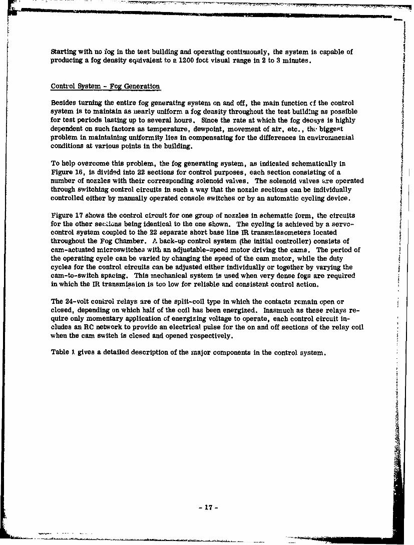
Besides turning the entire fog generating system on and off, the main function cf the controlsystem is to maintain as nearly uniform a fog density throughout the test buildhng as possiblefor test periods lasting up to several hours. Since the rate at which the fog decays is highlydependent on such factors as temperature, dewpoint, movement of air, etc., thy. biggeRtproblem in maintaining uniformity lies in compensating for the differences in environmentalconditions at various points in the building.
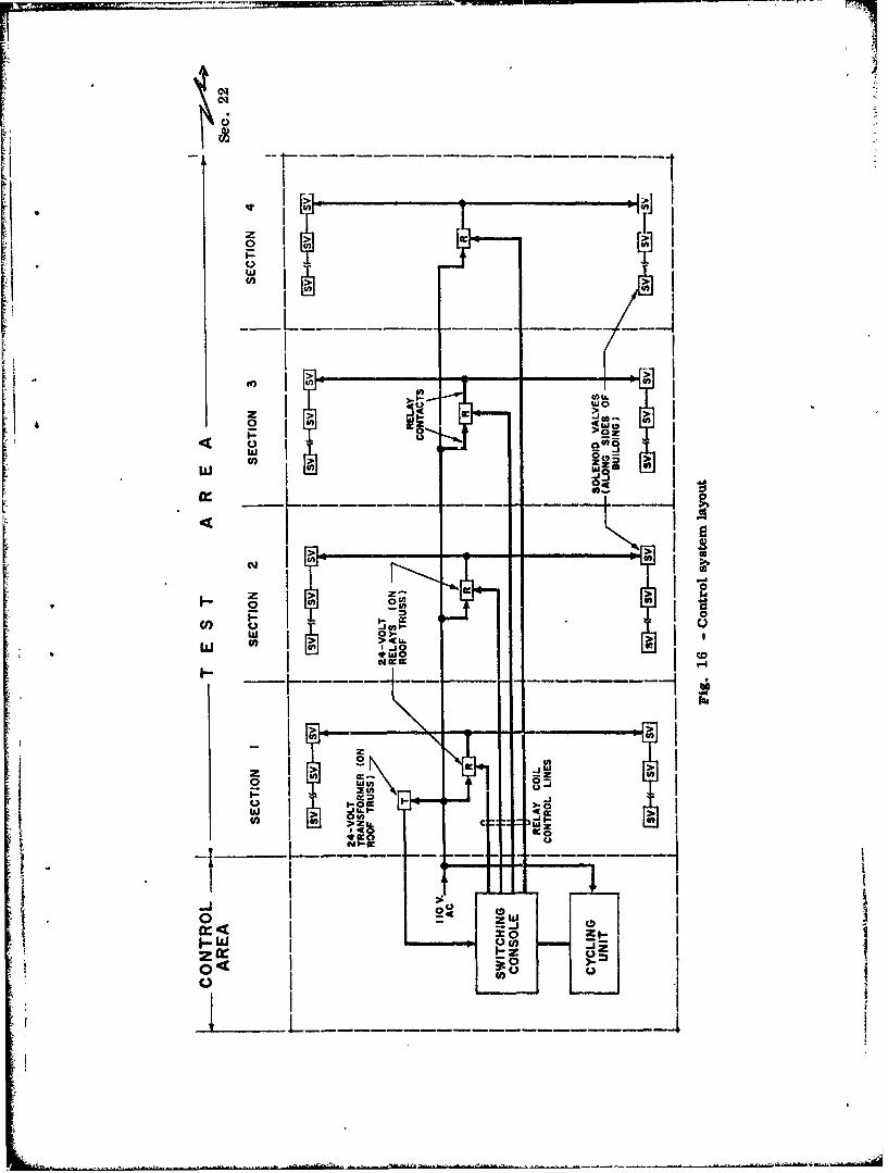
To help overcome this problem, the fog generating system, as indicated schematically inFigure 16, is divided into 22 sections for control purposes, each section consisting of anumber of nozzles with their corresponding solenoid valves. The solenoid valves tre operatedthrough switching control circuits in such a way that the nozzle sections can be individuallycontrolled either by manually operated console switches or by an automatic cycling device.
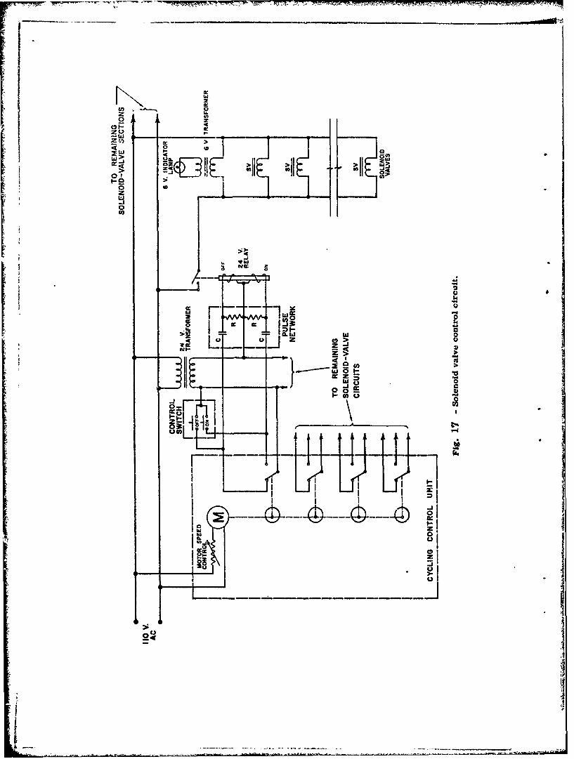
Figure 17 shows the control circuit for one group of nozzles in schematic form, the circuitsfor the other sec:ulkns being identical to the one shown. The cycling is achieved by a servo-control system coupled to the 22 separate short base line ER transmissometers locatedthroughout the Fog Chamber. A back-up control system (the initial controller) consists ofcam-actuated microswitches with an adjustable-speed motor driving the cams. The period ofthe operating cycle can be varied by changing the speed of the cam motor, while the dutycycles for the control circuits can be adjusted either individually or together by varying thecam-to-switch spacing. This mechanical system is used when very dense fogs are requiredin which the IR transmission is too low for reliable and consistent control action.
The 24-volt control relays are of the split-coil type in which the contacts remain open orclosed, depending on which half of the coil has been energized. Inasmuch as these relays re-quire only momentary application of energizing voltage to operate, each control circuit in-cludes an RC network to provide an electrical pulse for the on and off sections of the relay coilwhen the cam switch is closed and opened respectively.
Table I gives a detailed description of the major components in the control system.
-17 -
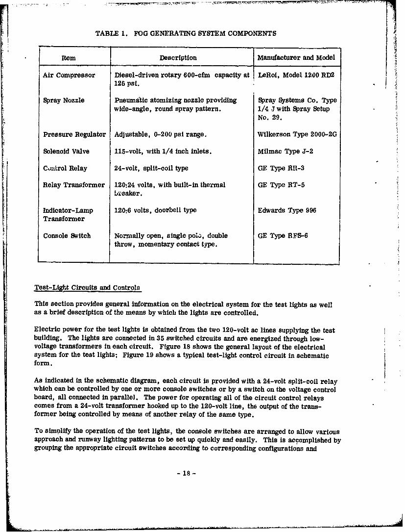
TABLE 1. FOG GENERATING SYSTEM COMPONENTS
Item Description Manufacturer and Model
Air Compressor Diesel-driven rotary 600-cfm capacity at LeRoi, Model 1200 RD2125 psi.
Spray Nozzle Pneumatic atomizing nozzle providing Spray Systems Co. Typewide-angle, round spray pattern. 1/4 J with Spray Setup
No. 29.
Pressure Regulator Adjustable, 0-200 psi range. Wilkerson Type 2000-2G
Solenoid Valve 115-volt, with 1/4 inch inlets. Milmac Type J-2
Conirol Relay 24-volt, split-coil type GE Type RR-3
Relay Transformer 120:24 volts, with built-in thermal GE Type RT-5bLieaker.
Indicator-Lamp 120:6 volts, doorbell type Edwards Type 996Transformer
Console Switch Normally open, single pol,, double GE Type RFS-6throw, momentary contact type.
Test-Light Circuits and Controls
This section provides general information on the electrical system for the test lights as wellas a brief description of the means by which the lights are controlled.
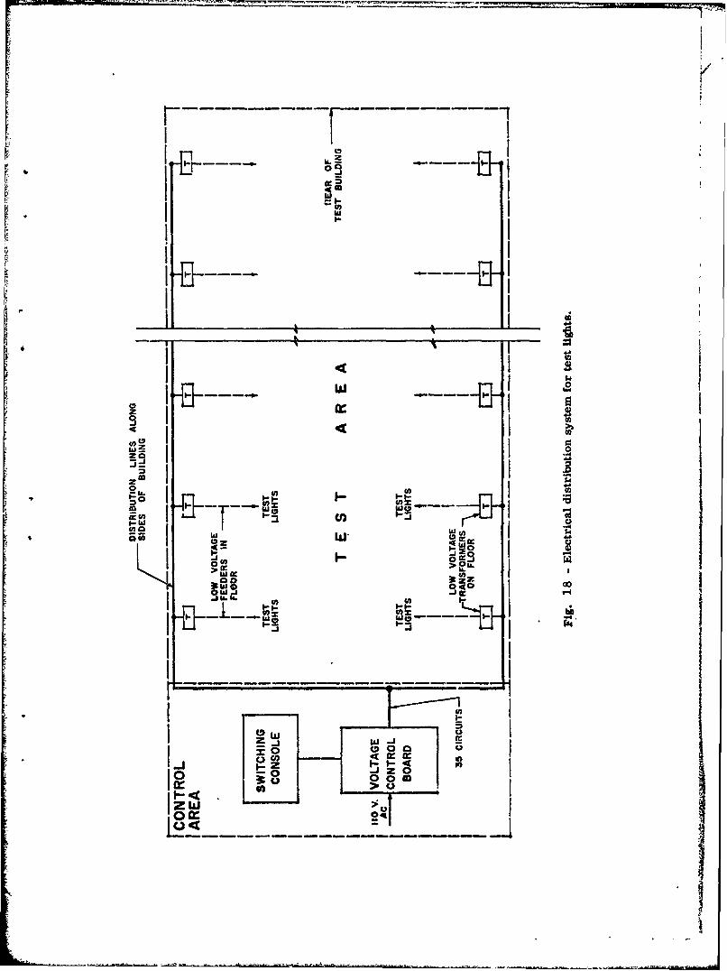
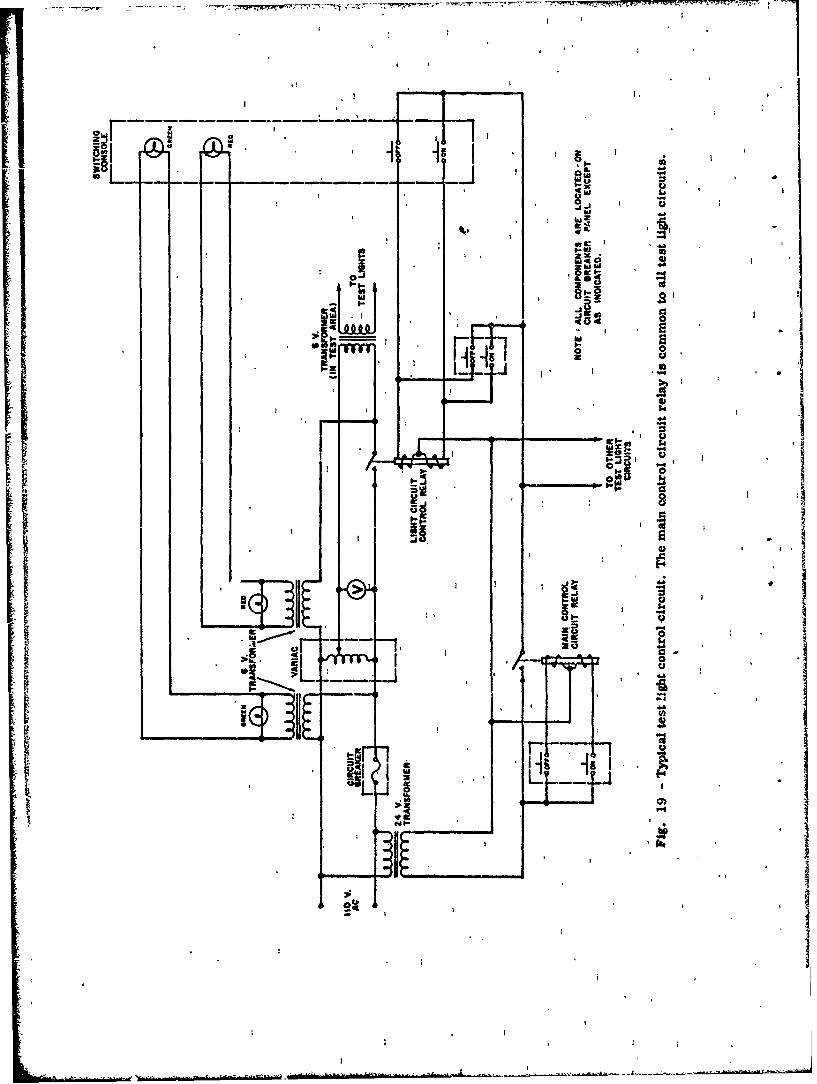
Electric power for the test lights is obtained from the two 120-volt ac lines supplying the testbuilding. The lights are connected in 35 switched circuits and are energized through low-voltage transformers in each circuit. Figure 18 shows the general layout of the electricalsystem for the test lights; Figure 19 shows a typical test-light control circuit in schematicform.
As indicated in the schematic diagram, each circuit is provided with a 24-volt split-coil relaywhich can be controlled by one or more console switches or by a switch on the voltage controlboard, all connected in parallel. The power for operating all of the circuit control relayscomes from a 24-volt transformer hooked up to the 120-volt line, the output of the trans-former being controlled by means of another relay of the same type.
To simplify the operation of the test lights, the console switches are arranged to allow variousapproach and runway lighting patterns to be set up quickly and easily. This is accomplished bygrouping the appropriate circuit switches according to corresponding configurations and
- 18-
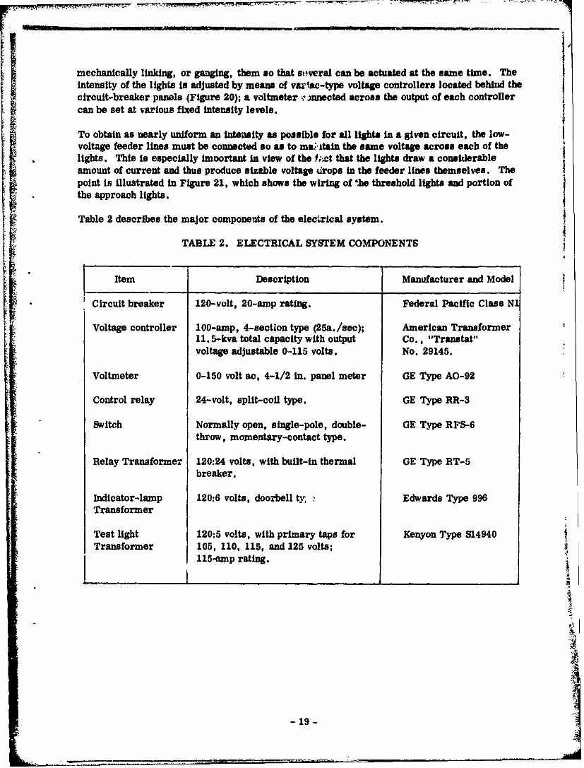
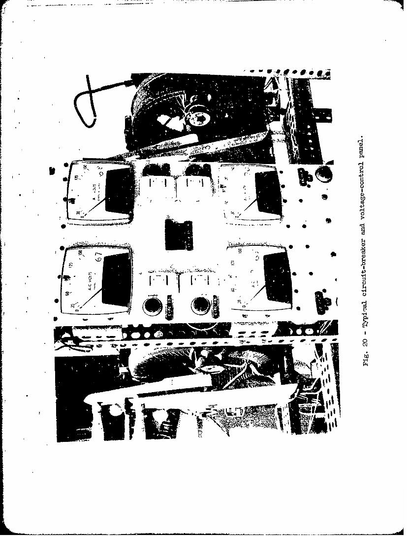
mechanically linking, or ganging, them so that soveral can be actuated at the same time. Theintensity of the lights is adjusted by means of vaxiac-type voltage controllers located behind thecircuit-breaker panels (Figure 20); a voltmeter e 3nnected across the output of each controllercan be set at various fixed intensity levels.
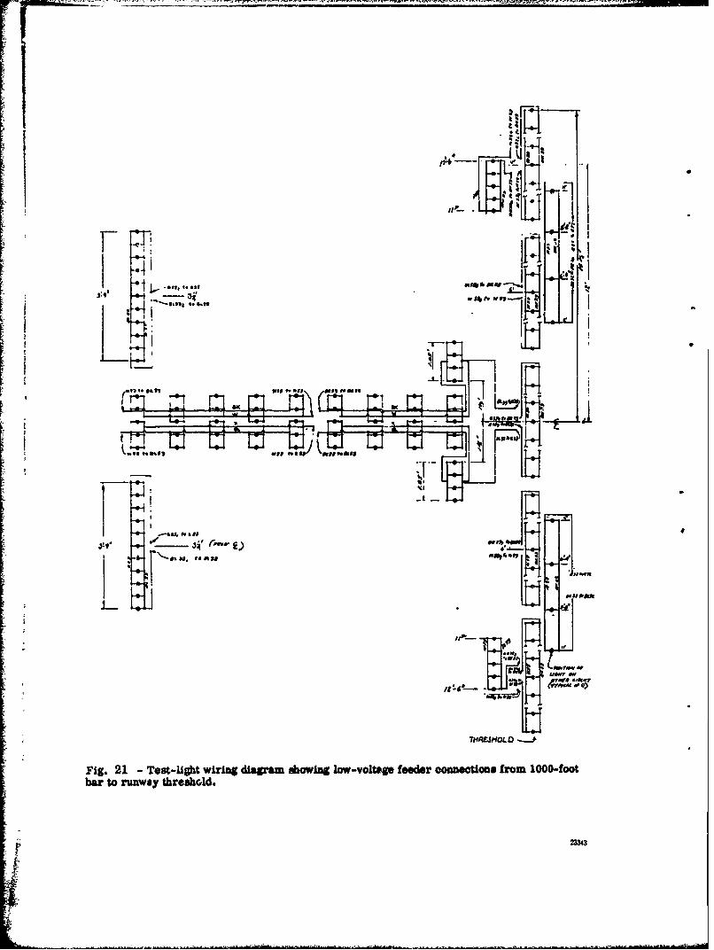
To obtain as nearly uniform an intensity as possible for all lights in a given circuit, the low-voltage feeder lines must be connected so as to mai tain the same voltage across each of thelights. This is especially imoortant in view of the f;.ct that the lights draw a considerableamount of current and thus produce sizeble voltage drops in the feeder lines themselves. Thepoint is illustrated in Figure 21, which shows the wiring of 'he threshold lights and portion ofthe approach lights.
Table 2 describes the major components of the electrical system.
TABLE 2. ELECTRICAL SYSTEM COMPONENTS
, - ••
Item Description Manufacturer and Model
Circuit breaker 120-volt, 20-amp rating. Federal Pacific Class N1
Voltage controller 100-amp, 4-sectlon type (25a. /see); American Transformer11. 5-kva total capacity with output Co., "Tranatat"voltage adjustable 0-115 volts. No. 29145.
Voltmeter 0-150 volt ac, 4-1/2 in. panel meter GE Type AO-92
Control relay 24-volt, split-coil type. GE Type RR-3
Switch Normally open, single-pole, double- GE Type RFS-6throw, momentary-contact type.
Relay Transformer 120:24 volts, with built-in thermal GE Type RT-5breaker.
Indicator-lamp 120:6 volts, doorbell ty, Edwards Type 996Transformer
Test light 120:5 volts, with primary taps for Kenyon Type 814940Transformer 105, 110, 115, and 125 volts;
115-amp rating.
I_19_
4
NI
- 19 - --
- A -- ~ - -
F :o PRAT-r
£SEVAeT/D.,V AS aST4o4ai$4ed& v 0 ivateR
/>CORR. MWETAL S/DINIG
~A~pMAT,?u -R:; kGZ P/CIAR COAlS If AV44C
'i -ASMA~ ARO-CAVCREWe
SCAI.S. I" ZO'
~i-'PRATT 1qoo RUS ON Poks*.5 or 6vPO7 140 1,40,. 'c. 1.: ................
.0orOIN CL. -&srl
17rVA44E CIr 1 4f. RAIL g.C~,
CA N.C - I
SC.4Le -,
P-MM"
ZjVIA. AS& Ij jC
14'- J IC YO*
c 2SJ4T/O~ A.~£$TASTONJ
60EWIZIl 1
W AAA
Fig I-~i Bsodmii.A ftstWii
dIi II�I 2MHz ¼ 1. jIi '4#!4JA
�. '4 e4
Ii\�IiI'�'K a
� -74. I** ' -
*1�.� " .�II rnf,11 �;%5c� ii
I iiI.. I ,, .� ,1/� �;' if;if - I� / '.
I
/ C
t.I.J Ie C� -,.. lii
�j�z*4�� *..:, --
C S LC�. t� * ., LII� .... b�t&; .� -
-'I � �:IiI.'* I�*..' IL...5 .&I.,.. � I
II. .
'. .1 �--4
f�
j �I0 '
* . *-- .b. *1
I' � __________________ -Ii1 '� "
-. - '!: -rI. ...1�
I
-Z_-
" o."qkM PMA A iha 4
forW1~CA A WR#ý e, -t
iid
is' tal CADI M SAW SWAP
fr~ ~ ~ ~ ~ wio 0W itopA
PoorI IT2~ MIJAIL 1MA"j .a.*W
'7r '#w#W -s
PSI.
>2 I
04 -4" ýO
SM 1~-4ia -#ý
'A~Y jV**''I Me? SV 'Vh
Mir 2 -Stmuctual details of test building
1 010
0jlox,
-qp,
I ýw
Y4k
MAP:
4;,
r-:1
F43
ILF-rIu

*0 j
'IL
.4J
i
V 94
I11 [.
ii -.--- - /D�AJ�Jr 2-a14. &�L-J�.
/'I,.
- ., I ( * 'I
Ii I .2 I'
'I III - II
�/
.�f4Z?�d�gf4J�fh'P - - J flh�E�A/JE .�-
JS�A � I630RPM -2#� V. �
I.
23�-'�? � -
..&gauL.eAjA....�ffZ* WF A 8,, .
- .* UF'1. -
ji 1
* I
I'. I
A
.�..21-72�# (�NF*4FEW4d�r�f�)J -
/
-... .- " . ,. ...- -. `.!
Li _ 2 * i_____
.sou -4 . .
______.______.___ _ ______._
•:•k _-:..•-- -- #F -4:~ -.. .
/ ~ I,
144I
Fig. 6 Tramway carriage structural featurs.
.•• •q.'.• ° • •• -°t"-•1- •, ,• ---'; o z.=,•'., ' :.,••',•• • • ••,:' t``":•; ? °• `•••.'` L~• ,.=Ja,,• ..7 .•.V• r
Ii
• i
-ii_
" - -"~' 1
'21
7 T
H- - I -4
J.JE' .. ~.'c~.&~ .
" I I ! -- . . . . . ........ ....
Le IL. . ///"o ,€ ,,,,,,,.
k it
aa
"!T
Al v
Fi-g. 7.. ... .whe rck
L Fig. 7 - Carriage wheel truck details.
/
I I� HI� I�I
II �c�4I�) � �
[.& ' ..
1l1�Ji2L\J'UI
,�l4'I,
L2:.
I. . . -4
4 I
-r-�� I:1 '66, *
. I* II.1 I
*1
'6 I . ,�' II "i'- *v. -
* 'f�Z�.7� I 4 Ig.�. .- 1±. I
+j-.� �:)�i A, .
ilif_ i�Tnr
LJJ
j I
4
4�1
I4
I -
PIP
g NS.... . I rl ... .J, ' "t
C- - --. 1$,.-
i .i• I: ••XI+ xI+X.,
_ _ _ _ 'Ii 4
' I _. -. ---- - Ti .. ...t..
4,. K i i
4'1
:"--_•_.,,•('. . -'-' . ,.. *
li
44
E-'<g.I
Fig. 8 - Cockpit trolley details.
- --- *- --. '
[I I xi�4:
4.
.' �p.
2 � I£
.4
. 0
0C
0
-0
I I
____________________________________________________________________
-� H-
__________
I
OfC
:01 AO
~~O$
.4. ',~j Mt...~, ~ f~aaS)v*~jL *7 1. W.M T W71 s47, *
-Pw 6o MR so.#rs.., UfS t 14 , .) *~.V 4t7
InVU .i 1 -. A .r.vt -w I.." 4rV O4o'.lUvAN .a" NI^ - *4A 16- &A. Snft 1vP
I~I-
jc~~-*-
~~1Wv#
*A l
AD - ~aAD. , I**'**- y .*so,-, .e.tw - -
Ov,4 .a
*~~~r $CA"*I*..
IrM
AM M.a.W
.-0*.*.a.***f- -O Aft"" off
4t V.P .lr ro - ff 21
d~t *'*4
-I in, E5. L
.4'.p A ff*fl~~~~~~~~'o
A.jIb* . )Ie4A.dU~*5am so
. ....... .......
I-a.- um~ SOVAW
4 ..... Ltc~tr 'no
W.O.M.1
I- Woo w
^m- ow ~*. a" -wjw 440K
AL M WW.lO&O01
Fig. 114 Fog *unn "dg Oingdlam
Cj
- r-
7' MI " +)+'-•:+'+'•q "-.'-,-
0 -4P4
0°
-+/ + - .
,,
.:+ ..+
I? *,-• C
.0 t ' ,, -,',I•.
AA
I, *D - -
• z"
""C , +. +,..• , . . .+ *.i.• C
PressureIlegulators
2 For UpperNozzles
(,Not Shown)
Solenoid ,prayValve Nozzle
07-
4 Pressure4;0, Regulators
fit
z*
ej
41,
t'a er 04 RAir Lines
Fig. 14 Typical nozzle ass(,!Rbly.
A
U
4 � &-'4. -
A . - �
C,.'
4 *
I'
I
13:
- Fog .;pr&y 2� V � 0
OILw>0
JO
-1-~~z
In2 I8
z t
04.i
4oU. P
ow 2f =>1
IWO1
Cou
0.40
00..0 C
U)U
- Ir.0 1m
oo
w z15 30=0
IU 0
ILI
.0
0 0-
> .UIw 0
0-
0 0
0 0 co
> 0
0 -r w 0II-I
w
4.j '
4L4.
.~ IWO I f -I Vlz F,'
- wa~ g .1
0-
ouo
0
04b.
ILI
ow m
a,-V .rw _ aw
a iE WI,
U k7.1ags O s
- ,,
W59uua*lfms
*41
THWHOL0 --. t
Fig. 21 -Test-light wiring diagram showing low-voltage feeder conneetions from 1000-footbar to runway threshold.
2W34