Embed Size (px)
Citation preview
UNCLASSIFIED
AD 410255
DEFENSE DOCUMENTATION CENTERFOR
SCIENTIFIC AND TECHNICAL INFORMATION
CAMERON STATION. ALEXANDRIA, VIRGINIA
UNCLASSIFIED
I,.
I,
il
NOTICE: We. goverumn; or other drawings, speci-fications or other data arr used for k.4y :.other than in c. :tiLx witih a d.efinitely relatedgovernment prcurement operation, the U. S.Government thex,2by incurs no responsibility, nor anyobligation vhat soever; and the fact that the Govern-ment may have 1--rmlated, furnished, or in any waysupplied the said drawings, specifications, or otherdata is not to e regarded by implication or other-vise as in any ,nner 3 icensing the holder or anyother person or corporetion, or conveying any rightsor permission t- mantu fcture, use or sell anypatented inventi.on thai, may in any way be relatedthereto.
FOR ERRATA
AD
410 255
THE FOLLOWING PAGES ARE CHANG:f
TO BA".IC DOCUMENT
'I

A OIVISIION OP NORTN AMERICAN AVIAVION. iNO.
R-3952S1 July 1963
Page rev. 9 August 1963ISupersedes 10 July 1963
END ITEM CONFIGURATION CHART
Specification Production
Issue ECP'S Effectivity
Basic NA225173
1 July 1963 MA5-3 and subsequent
MA5-5
MA5-8
MA5-1I1
MA5-16
MA5-23
MA5-31
MA5-38
MA5-39
MA5-42
MA5-55
MA5-59
MA5-62
MA5-65
MA5-70
MA5-71
MA5-72
MA5-76
MA5-77
MA5-80
MA5 -84
The YLR105-NA-7 (Sustainer) engine defined by this specification incorporates theabove listed engineering changes which give it a baseline configuration of YLR105-NA-'
MD 5x7xllx!2 12xL1x20 2x._ 28x- .
ii-a
FORM 608- PLATE REV. 1-58

A CIVISION OF NORTMI AMERICAN AVIATION. INC.
R-3952S1 July 1963
Page rev. 9 August 1963Supersedes 10 July 1963
SUPPLEMENTARY INFORMATION
YLRIO5-NA-7 MA5-MD Ident. No. ECP No. Description
1 none Replacement of Head Suppression andPropellant Utilization Valve Assemblies
2 none Changes to Pneumatic Start System ControlAssembly
3 none Improvement of Lube and Fuel DrainageProvisions
4 none Replacement of Thrust Chamber Injector-Dome Flush Nozzle
5 none Installation of Tapered Inducer onTurbopump Assembly
7 3 Redesign of Fuel Pump Elbow Seal onTurbopump Assembly
11 5 Replacement of Mixture Ratio Control Assembly13 31112 Addition of Vernier Thrust Chamber Hypergolic
(Pyropboric) Ignition System14 39R2 Addition of Fuel Pressure Sensing Switch15 42 Rede.ign of Fuel Manifold Start System
Pressure Switches17 55 Replacement of Studs on Fuel Start Tank and
Vernier Feed Tank20 62R1 Replacement of Engine Electrical Relays on
Inter(onnecting Box21 11112 & 72R1 Insiallition of Special Purpose Vernier
Diodes on Interconnecting Box; and Changesto Engine Relay Box Redundant Head SuppressionSolenoid Control Circuit
22 76112 Change- to Pneumatic Start System ControlA-semblx
23 59R3 Replacement of Oxidi7er 1,ent and High PressureRelief Valve Assembly
25 77 Redesign of LOX Bootstrap Scoop26 70R1 Replacement of Lube Tank Pressurizing Valve
Ah-;embly27 80111 Incorporation of Kel-F Liner Oxidizer Pump
Inlet Adapter28 65 & 71 Redesign of Lube Oil Drain System; and,
Turbine Exhaust Aspirator31 84 Replacement of Aluminum "B" Nutsnone 8 Reldentification of Accumulatornone 16 Revise Packaging Requirementsnone 23R1 Changes to Purity (Contamination) Requirementsnone 38R3 Incorporation of Furnace Brazed Thrust Chamber
ii-b
FORM 008.8 PLATE REV. 1-58

A DIV4a6ON OP NOAT AMERUICA AVIATION. F4CL
R-195PS5Page rev. 9 Augut 1963
3.5 Drawings and data.- The following Rocketdyne dravings and data shall
form a part of this specification:
(a) Engine assembly (sustainer) 10&?001
(b) Markings installation 10(2004
(c) Control system installation (gas
generator system) 3002001
(d) Propellant feed system installation 4002001
(e) Lubrication system installation 35OZ. J
(f) Electrical system installation 5002001
(g) Engine loose equipment 6502001
(h) Expendable loose equipment 6502002
(i) Pyrotechnic loose equipment 6502003
(j) Hydraulic system installation 6002001
(k) Exhaust system installation 3002010
Model identification numbers
ENGINE AND MPL MD NUMBERS
YLR105-NA-7 5x7xllxj1_2 _IX._ 22X21 20_ x.
3.5.1 Before contract.- Not applicable.
3.5.2 After contract.- Not applicable.
17
FORM 4OS- PLATE REV. 1.5

it7
-I__ I
C--:)-r4
A DIVISION OF NORTH AMERICAN AVIATION. INC.
rl CANOGA PARK, CALIFORNIA
DDC
I JUL 1719
~TiSIA D

R-39 52S
MODEL SPECIFICATION
LTIQJID PROPELLANT ROCKET ENGINE
ROCKETDYNE MODEL YLR105-NA-7
(SUSTAINER)
A DIVISION OF NORTH AMERICAN AVIATION. INC.
6633 CANOGA AVENUECANOGA PARK, CALIFORNIA
(MA-5 Block I)
PREPARED BY
R. B. ScottContract Specifications
APPRqVED BY',.L/ -: .,'/ ..-
.1 ,J. Brennan/Aief Engineer
Liq(idd Rocket Engineering
NO. OF PAGES 99 & iX REVISIONS DATE 1 July 1963
DATE REV. MY PAGES AFFECTED REM A R KS
FORM R 0-G 'PLATE-

A DIVISION OF NORTH AMERICAN AVIATION. INC.
R-,49.m&
END ITEM CONFIGURATION CHART
Specification ECP's ProductionIssue Effectivity
Basic NA225173
1 July 1963 MA5-3 and subsequent
MA5-5
MA5-8
MA5-11
MA5-16
MA5-23
MA5-31
MA5-38
MA5-39
MA5-42
MA5-55
MA5-59
MA5-62MA5-65
MA5-70
MA5-71
MA5-72
MA5-76
MA5-77
MA5-80
MA5-84
The YLR105-NA-7 (Sustainer) engine defined by this specification incorporatesthe above listed engineering changes which give it a baseline configuration ofYLR105-NA-7 MD7x3l 1 .xI7:.O 2x21 28x31.
ii-a
FORM 60 U PLATE REV. 1.-5

DIVISION OF NORTH AMERICAN AVIATION. INCe
R-10KOR
SUPPLEMENTARY INFORMAT ION
YLR89-NA-7 MA5-MD Ident. No. ECP No. Description
1 none Replacement of Head Suppression and PropellantUtilization Valve Assemblies
2 none Changes to Pneumatic Start System Control Assembly3 none Improvement of Lube and Fuel Drainage Provisions4 none Replacement of Thrust Chamber Injector-Dome Flush
Nozzle5 none Installation of Tapered Inducer on Turbopump Assembly6 11R2 Installation of Special Purpose Vernier Diodes on
Interconnecting Box7 3 Redesign of Fuel Pump Elbow Seal on Turbopump Assembly11 5 Replacement of Mixture Ratio Control Assembly13 31R2 Addition of Vernier Thrust Chamber Hypergolic
(Pyrophoric) Ignition System14 3912 Addition of Fuel Pressure Sensing Switch15 42 Redesign of Fuel Manifold Start System Pressure
Switches17 55 Replacement of Studs on Fuel Start Tank and Vernier
Feed Tank20 62R1 Replacement of Engine Electrical Relays on Inter-
connecting Box
21 72R1 Changes to Engine Relay Box Redundant Head Suppres-sion Solenoid Control Circuit
22 7612 Changes to Pneumatic Start System Control Assembly23 59R3 Replacement of Oxidizer Vent and High Pressure Relief
Valve Assembly
25 77 Redesign of LOX Bootstrap Scoop26 70R1 Re placement of Lube Tank Pressurizing Valve Assembly27 80R1 Incorporation of Kel-F Liner Oxidizer Pump Inlet
Adapter28 65 & 71 Redesign of Lube Oil Drain System; and, Turbine
Exhaust Aspirator
31 84 Replacement of Aluminum "B" Nutsnone 8 Reidentification of Accumulatornone 16 Revise Packaging Requirementsnone 23R1 Changes to Purity (Contamination) Requirementsnone 38R3 Incorporation of Furnace Brazed Thrust Chamber
ii-b
FORM @Of 0 PLATE REV. 1-0

A DIVISION OF NORTH AMERICAN AVIATION. INC.
SPECIFICATION CHANGE INDEX
Specification No. R-3952S
Item Affected
MA5 Pages YIR105-NA-7SCN No. ECP No. SCN Date Affected MD Ident. No.
1 * various * 1 July 1963 various * various *
NOTE: SCN 1 to R-3952S incorporates the sustainer portion of the following
approved SCN's to R-285OaS:
Item Affected
R-285OaS MA5 R-285OaS Paragraphs YLR105-NA-7SCN No. ECP No. SCN Date Affected MD Ident. No.
2 68 24 July 1962 3.5, 3.5.3 2411 73RI 5 December 1962 3.5 30
ii-c
FORM 0 6S PLATE REV. 1l

A iv*.o MRT .-- -. M SPECIFICATION CHANGE NOTICENumber
(re~f: R-285OaS/SCN il)* 14
SEURTY (UNCLASSIFIED R ICRICTIOY CONFIDENTIAL out. 1 July 1963
SECRET 0I SUPERSEDES Dot_________________
1. FOR ECP NO. 2. NOMENCLATURE AND MODEL 3. SPECIFICATION NO.
NA-MA573Rl(ref)* Rocketdyne R-3952SILiquid-Propellant Rocket Engine
Model YLR105-NA-7 (Sustainer)
4. CONTRACT 5. CONTRACTUAL AUTHORIZATION FILE OPPOSITE
AFO0i(694'j-58 CCN4O(N58-874)*SPCPAEN.1
6. PRODUCTION EFFECTIVITY:
NA 225181 and subsequent
7. EFFECT OF CHANGE ON SPECIFICATION CONTENT:
Paragraph 3.5 Drawings and data
Change YLI105-NA-7 MD number identification to incorporate MD10.
*NOTE: Previously proposed and authorized as noted.
form 608-B-8

ON AERTD AO SPECIFICATION CHANGE NOTICE1
Number
(ref: R-285OaS/SCN 2) * 2 4UNCLASSIFIED F age .
SECURITY 1 July 1963CLASSIFICATION CONFIDENTIAL
Date
SEET SUPERSEDES Date
1. FOR ECP NO. 2. NOMENCLATURE AND MODEL 3. SPECIFICATION NO.
Rocketdyne
NA-MA5-68 (ref)* Liquid-Propellant Rocket Engine R-3952SModel YLR105-NA-7 (Sustaiiier)
4. CONTRACT 5. CONTRACTUAL AUTHORIZATION FILE OPPOSITESPEC. PAGE NO. 17
AF04(694)-58 CCN 24 (N58-315)*
6. PRODUCTION EFFECTIVITY:
NA223192 and subsequent.
7. EFFECT OF CHANGE ON SPECIFICATION CONTENT:
Paragraph 3.5 Drawings and data
Change YLRI05-NA-7 MD number identification to incorporate MD24.
* NOTE: Previously proposed and authorized as noted.
4F
Form 60S-B-8

A OIVIGION OP NORTH AMCRICA* AVIATION. INC. PECIFICATION CHANGE NOTICE1
UNLA E Nuref: R-2850aS/SCN 2)*1 3F1
UNCLASSIFIED [ ae o
SECURITY CONFIDENTIAL 1 July 1963CLASSIFICATION CDot
SECRET SUPERSEDES Date -
1. FOR ECP NO. 2. NOMENCLATURE AND MODEL 3. SPECIFICATION NO.Rocketdyne
NA-MA5-68 (ref)* Liquid-Propellant Rocket Engine R-3952SModel YLR105-NA-7 (Sustainer)
4. CONTRACT 5. CONTRACTUAL AUTHORIZATION FILE OPPOSITESPEC. PAGE NO. 18
AF04(694)-58 CCN24 (N58-315)*
6. PRODUCTION EFFECTIVITY:
NA225192 and subsequent.
7. EFFECT OF CHANGE ON SPECIFICATION CONTENT:
Paragraph 3.5.3 Weights
Change the paragraph to read as follows:
Weights.- The dry weight of the YLR1O5-NA-7 shall not exceed 1028 pounds.
The wet weight after normal shutdown shall not exceed 1152 pounds. The
wet weight with all systems filled to capacity shall not exceed 1417
pounds.Estimated
Assembly Weight, Ib
Thrust chamber 367Mount, gimbal assembly 18Turbopump installation 229Oxidizer system 46Fuel system 40Gas generator system 45Lubrication system 21Electrical system 23Pneumatic system 7Exhaust system 85Hydraulic system 45Ignition system 6
Dry weight total '932Wet weight total 1086
fw Wet weight burnout 1024Form 608.P8
* NOTE: Previously proposed and authorized as noted.

A CIVISION OP NORTA AMKRICAN AVIATION. INC. SPCIFICATION CHANGE NOTICE
Number 1
(ref: R-285OaS/S1CN 2)*UNCLASSIFIED EA Poo. f.
SECURITYCLASSIFICATION CONFIDENTIAL D--- 1 July 1963
SECRET El SUPERSEDES Date
1. FOR ECP NO. 2. NOMENCLATURE AND MODEL 3. SPECIFICATION NO.
RocketdyneNA-MA5-68 (ref)* Liquid-Propellant Rocket Engine R-3952S
Model YLRI05-NA-7 (Sustainer)
4. CONTRACT 5. CONTRACTUAL AUTHORIZATION FILE OPPOSITESPEC. PAGE NO. 18
AF04(694)-58 CCN24 (N58-315)*
6. PRODUCTION EFFECTIVITY:
NA225192 and subsequent.
7. EFFECT OF CHANGE ON SPECIFICATION CONTENT:
Paragraph 3.5.3 Weights (continued)
EstimatedAccessory equipment Weight, lb
Sta' t system 96
Dry weight total 96Wet weight total 331
Wet weight burnout 128
* NOTE: Previously proposed and authorized as noted.F 0
Form 608-B-8

A DIVISION OF NORTH AMERICAN AVIATION. INC
R-912S
TABLE OF CONTENTS
Paragraph Page
1. SCOPE ----------------------------------------------------------- 1
1.1 Scoe -------------------------------------------------------- 1
1.2 Classification ----------------------------------------------- 1
1.2.1 Function -------------------------------------------------- 1
2. APPLICABLE DOCUMENTS -------------------------------------------- 2
3. REQIREMENTS ---------------------------------------------------- 4
3.1 General------------------------------------------------------4
3.1.1 Model Specification --------------------------------------- 4
3.1.2 Qualification and Acceptance-------------------------------4
3.2 Mockup-------------------------------------------------------4
3.2.1 Rocket engine changes--------------------------------------4
3.3 Performance characteristics ---------------------------------- 4
3.3.1 Rocket engine operating regimes ---------------------------- 5
3.3.2 Ratings --------------------------------------------------- 5
3.3.3 Estimates ------------------------------------------------- 7
3.3.4 Components ------------------------------------------------ 7
3.3.5 Starting -------------------------------------------------- 7
3.3.6 Shutdown -------------------------------------------------- 8
3.3.7 Malfunction ----------------------------------------------- 8
3.3.8 External power -------------------------------------------- 9
3.3.9 Propellants and fluids ------------------------------------ 10
3.3.10 Control -------------------------------------------------- 12
3.4 Environmental and load factors -------------------------------- 14
3.4.1 Environmental conditions ---------------------------------- 14
3.4.2 Flight and ground loading conditions ----------------------- 15
3.4.3 Limiting zone temperatures -------------------------------- 16
iii
FORM 808 8 PLATE: REV. I-E1l

A DIVISION OP NORTh AMERICAN AVIATION INC.
R-3952S
TABLE OF CONTENTS
Paragraph Page
3.5 Drawings and data --------------------------------------------- 17
3.5.1 Before contract ------------------------------------------- 17
3.5.2 After contract -------------------------------------------- 17
3.5.3 Weights --------------------------------------------------- 18
3.5.4 Overall dimensions ----------------------------------------- 18
3.6 Components and s stems --------------------------------------- 18
3.6,1 Propellant and other fluids systems ----------------------
3.6.2 Power control --------------------------------------------- 20
3.6.3 Electric system--------------------------------------------22
3.6.4 Ignition system -------------------------------------------- 24
3.6.5 Lubrication system ---------------------------------------- 24
3.6.6 Thrust chamber assembly ------------------------------------ 25
3.6.7 Tanks ----------------------------------------------------- 27
3.6.8 Burst diaphragms ---------------------- 28
3.6.9 Accessory drives ------------------------------------------ 28
3.6.10 Accessory equipment --------------------------------------- 28
3.7 Fabrication ------------------------------------------------- 28
3.7.1 Materials ------------------------------------------------- 28
3.7.2 Processes ------------------------------------------------- 29
3.7.3 Standards -------------------------------------------------- 30
3.7.4 Parts list ------------------------------------------------ 31
3.7.5 Changes in design ----------------------------------------- 31
3 8 Iden' ification of product ------------------------------------- 32
3.8.1 Connections ----------------------------------------------- 32
3.8.2 Components ------------------------------------------------ 32
3.9 General additional information -------------------------------- 33
3.9.1 Propellant utilization ------------------------------------ 33
3.9.2 Thrust alig ment ------------------------------------------ 33
iv
FORM 08 B PLATE REV. 1.58

A IV60ION or NORTH A1w6RICAN AVIATION. INC.
TABLE OF CONTENTS
Paragraph Page
4. QUALITY ASSURANCE P3ROVISIONS ---------------------------- 34
4.1 Classification of tests ------------------------------ 34
4.2 Tests and test methods ------------------------------- 34
4.2.1 Alternate test fluids ----------------------------- 34
4.2.2 Qualification tests------------------------------- 34
4.2.3 Preliminary Flight Rating tests ------------------- 36
(6626) 1. SCOPE ------------------------------------------------- 36
(6626) 2. APPLICABLE DOCUMENTS----------------------------------- 36(6626) 3. REQUREIENTS------------------------------------------- 36(6626) 3.1 Reports: rocket engine and components --------------- 36(6626) 3.1.1 General------------------------------------------ 37
1)(6626) 3.1.2 Preliminary reports ------------------------------- 38
(6626) 3.1.3 Final report ------------------------------------- 39(6626) 3.1.4 Number and distribution of copies ----------------- 44
(6626) 3.2 Disposition of 1reliaiinary Flight Rating Test data - 44
(6626) 4. QUALITY ASSURANCE PROVISIONS ---------------------------- 44
(6626) 4.1 General--------------------------------------------- 44
(6626) 4.1.1 Test apparatus and procedures ---------------------- 45(66e',) 4.1.2 Test conditions---------------------------------- 46
(6626) 4.1.3 Parts failure and replacement --------------------- 47
(6626) 4.2 Rocket engine inspections and tests ------------------ 48
(6626) 4.2.1 Rocket engine tests ------------------------------- 48
(6626) 4.2.2 Rocket engine inspection after test --------------- 53
(6626) 4.3 Component inspection and tests ----------------------- 53(6626) 4.3.1 Previous component qualification ------------------ 53(6626) 4.3.2 Component inspection before tests ----------------- 53(6626) 4.3.3 Component tests --------------------------------- 54
)(6626) 4.3.4 Component inspection after tests ------------------ 56
V
FORM 60S 8 PLATE REV. 1.58

A DIV8IION OF NORTH AMERICAN AVIATION. INM
R-592S
TABLE OF CONTENTS
Paragraph )aze
(6626) 5. PREPARATION FOR DELIVERY ------------------------------- 57
(6626) 6. NOTES ------------------------------------------------- 57
(6626) 6.1 Intended use --------------------------------------- 57
(6626) 6.2 Definitions and symbols ----------------------------- 57
4.2.4 Acceptance tests --------------------------------- 57
(5132) 1. SCOPE ------------------------------------------------- 57
(5152) 2. APPLICABLE DOCUMENTS ---------------------------------- 57
(5152) 3. REQ 4IRMETS ------------------------------------------- 58
(5152) 3.1 Contractor's instructions, specifications anddrawings ------------------------------------------- 58
(5152) 3.1.1 Specifications ---------------------------------- 58
(5152) 3 1.2 Component calibration ---------------------------- 58
(5152) 3.1.3 Availal ility ------------------------------------ 59
(5152) 3.2 Acceptance test data -------------------------------- 59
(5152) 3.2.1 General ----------------------------------------- 59
(5152) 3.2.2 Log --------------------------------------------- 59
(5152) 4. QUALITY ASSURANCE PROVISIONS --------------------------- 61
(5152) 4,1 General -------------------------------------------- 61
(5152) 4.1.1 Test apparatus and procedures -------------------- 62
(5152) 4.1.3 Test temperatures -------------------------------- 62
(5152) 4.2 Acceptance tests ------------------------------------ 63
(5152) 4.2.1 Rocket engine inspection before a'ceptance tests- 64
(5152) 4.2.2 Rocket engine tests.- Sc!du-c "A ----------------- 64
(5152) 4.2.3 Rocket engine and component tests.- Schedule "B'"- 66
(5152) 4.2.4 Acceptance conditions ---------------------------- 66
(5152) 4.2.5 Rocket engine inspection test -------------------- 67
(5152) 4.2.6 Rejection and retest ----------------------------- 68
vi
FOR14 00 B PLATE REV. 1-50

ADIVISION Opp NORTH ANENKICAN AVIATION. INC.
R-39ML2
TABLE OF CONTENTS
Paragraph Page
(5152) 5. PREPARATION FOR DELIVERY -------------------------------- 68(5152) 6. NOTES------------------------------------------------- 68(5152) 6.1 Symbols and definitions ------------------------------ 68
5. PREPARATION FOR DELIVERY -------------------------------- 715.1 Application----------------------------------------- 715.2 Storage, shipment, and delivery ---------------------- 71
6. NOTES ------------------------------------------------- 726.1 Intended use---------------------------------------- 72
6.2 Symbols and definitions ------------------------------ 72
6.2.1 Definitions-------------------------------------- 72
6.2.2 Symbols------------------------------------------ 796.3 Rocket engine mockup procedure ----------------------- 80
6.4 Design and installation criteria --------------------- 80
vii
I'OR? 600 3 PLATE REV. 1.58

A DIVISION OF NORTH AMERICAN AVIATION. INC.
LIST OF ILLUSTRATIONS
F igures Page
la Estimated Nominal Altitude Performance YLR1O5-NA-7 81
lb Estimated Minimum Engine Specific Impulse vsEngine Mixture Ratio YLRlO5-NA-7 82
2 Estimated Sea Level Thrust & Thrust Coefficient vsChamber Nozzle Stagnation Pressure at NominalMixture Ratio YLR105-NA-7 Thrust Chamber 83
3 Estimated Characteristic Velocity vs Sea Level Thrustat Nominal Mixture Ratio YLRIO5-NA-7 Thrust Chamber 84
4 Estimated Sea-Level Specific Impulse vs Thrust atNominal Mixture Raijo YLR105-NA-7 Thrust Chamber 85
5a Developed Head vs Volumetric Flowrate at ConstantSpeed YLRI05-NA-7 Fuel Pump 86
5b Developed Head vs Volumetric Flowrate at ConstantSpeed YLRl05-NA--7 Oxidizer Pump 87
6a Cavitation Characteristics at Constant Speed andCapacity YLR1O5-NA-7 Oxidizer Pump 88
6b Cavitation Characteristic at Constant Speed andCapacity YLR1O5-NA-7 Fuel Pump 89
7 SLarting Sequence YLR89-NA--7, When Operated withYLR105-NA-7 and YLR101-1A-15 90
8 Cutoff Sequence YLRIO5-NA-7, When Operated withYLR89-NA,-7 and YLRIOI-NA-15 91
9 Power Control Arrangement, YLRIO5-NA-7, When Operatedwith YLR89-NA-7 and YLRIOI-NA-15 92
10 Schematic Rocket Engine Flow D agra-t, YLRlO5-NA-7, whenOperated with YLR89-NA-7 and YLRIOI-NA.-15 93
11 Start Power Control Interrelation with Rocket Engine,Functional Block Diagram of YLR89-NA-7 When Operatedwith YLR105-NA-7 and YLRIOI-NA-15 94
viii
FORM 609 5 PLATE REV. 1-58

A IVISION OF
NORTH AMERICAN AVIATION. INC.
R-195PS4
I.
LIST OF ILLUSTRATIONS
Figures Page
12 Shutdown Power Control Interrelation with Rocket Engine,Functional Block Diagram of YLR89-NA-7 When Operatedwith YLRIO5-NA-7 and YLRI01-NA-15 95
13 Fuel (RP-l) Density vs Temperature 96
14 Liquid Oxygen Density vs Temperature 97
15 YLR1O5-NA-7 Thrust Buildup Specification Altitudes:Zero to 10,000 feet 98
16 Limits of Propellant-Utilization Valve Angle vs EngineMixture Ratio at Sea-Level Standard Conditions 99
TABLES
Tables Page
I YLRI05-NA-7 Rocket Engine Rating at Standard Sea LevelStatic Conditions 6
II Alternate Test Fluids 35
ix
FORM 800 b PLATE REV. 1l5S

A DIVIBION Or
NORTH AMERICAN AVIATION. IN.
R-3952S
1. SCOPE
1.1 Scope.- This specification covers the requirements for the
YLR105-NA-7 liquid rocket engine.
1.2 Classification.- The rocket engine is a calibrated, fixed-thrust,
gimbal-mounted bipropellant rocket engine with a nominal sea-level
thrust rating of 57,000 pounds. Propellants shall be liquid oxygen
and hydrocarbon fuel. The propellants shall be supplied to the
thrust chamber from a turbopump powered by a gas generator using
the same propellant combination as the thrust chamber. The single
thrust chamber shall have an exhaust-nozzle expansion ratio of
25:1, and shall be regeneratively cooled with its fuel as the heat
transfer medium.
1.2.1 Function.- The sustainer engine is designed to operate with the
YLR89-NA-7 and the YLR101-NA-15 engines not a part of this speci-
fication. The interrelation of these rocket engines is as outlined
in Figures 7, 8, 9, 10, 11, and 12. The sustainer engine in addition
to providing thrust during launch and at altitude provides propel-
lants to the vernier engine, including vernier solo operation, pro-
vides pneumatic control for the vernier engine, and provides for
the distribution of dc electrical power to the booster engine. In
addition the sustainer engine also provides propellants for starting
the booster and vernier engine.
01
FORM 809-B PLATE REV b.5a
O CC 3 re WIA DIVISION OP NORTM AMERICAN AVIATION. IN,.
R-3952S
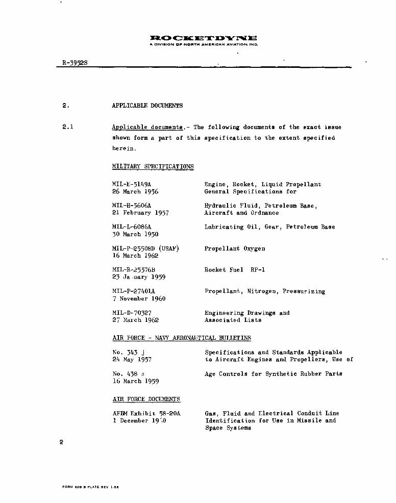
2. APPLICABLE DOCUMENTS
2.1 Applicable documents.- The following documents of the exact issue
shown form a part of this specification to the extent specified
herein.
MILITARY SPECIFICATIONS
MIL-E-5149A Engine, Rocket, Liquid Propellant
26 March 1956 General Specifications for
MIL-H-5606A Hydraulic Fluid, Petroleum Base,21 February 1957 Aircraft and Ordnance
MIL-L-6086A Lubricating Oil, Gear, Petroleum Base30 March 1950
MIL-P-25508D (USAF) Propellant Oxygen16 March 1962
MIL-R-25576B Rocket Fuel RP-l23 Ja ,uary 1959
MIL-P-27401A Propellant, Nitrogen, Pressurizing
7 November 1960
MIL-D-70327 Engineering Drawings and27 March 1962 Associated Lists
AIR FORCE - NAVY AERONAUTICAL BULLETINS
No. 343 j Specifications and Standards Applicable24 May 1957 to Aircraft Engines and Propellers, Use of
No. 438 n Age Controls for Synthetic Rubber Parts16 March 1959
AIR FORCE DOCUMENS
AFBM Exhibit 58-20A Gas, Fluid and Electrical Conduit Line1 December 19',0 Identification for Use in Missile and
Space Systems
2
FORMA 808 3 PLATEi R£V 1-58

A DIVI8ION O NORTH AMI4RICAN AVIATION. INC.
R-1952S
2.1 (Continued)
AF/BSD Exhibit 61-3A Specifications for Permissible1 September 1961 Contamination Limits and Inspection
Criteria for Liquid Oxygen, LiquidNitrogen, Fuel, Gaseous Oxygen,Gaseous Nitrogen, Instrument Air andHelium, Components, Handling Systemsand Fluids Use Limits
ROCKETDYNE DOCUMENT
R-3469 Associate System Contractor Respon-18 July 1962 sibility for Use With Rocketdyne
Propulsion System Contracts
SPACE TECHNOLOGY LABORATORIES
GM 6300.8-565B Contamination Limits and Evaluation2 February 1962 Methods for Hydraulic Systems and
Components, WS-107A-l, Weapons System.
3
FORMA 609 3 PLATE REV. I-58

A OIVISION Op NORTH AMERICAN AVIATION, INC
R-3952S
3. RE QUMEME S
3.1 General.-
3.1.1 Model Specifica ion.- The model specification has been prepared
using MIL-E-5150 as a guide with applicable provisions of MIL-E-
5149 incorporated. Publications referenced in the model speci-
fication and contained in ANA Bulletin 343 shall be applicable as
provided by the bulletin. Where the requirements of this model
specification and those of the documents listed in Section 2 are
at variance, the requirements of the model specification shall
govern.
3.1.2 Qualification and acceptance,- The qualification and acceptance
of any engine shall be in accordance with the tests specified
in Section 4 of this specification.
3.2 Mockup - The contractor shall prepare a full-scale mockup of the
rocket. engine when required by contract.
3.2.1 Rocket engine changes.- The Using Service shall be notified of
changes to the rocket engine features affecting the installation
made after approval of a mockup or the drawing package specified
in paragraph 3.5. Any mockup specifically required by contract
shall be kept curreni with approved changes for the duration of
the production contract, unless otherwise authorized. Changes
required by the procuring activity shall be subject to negotia-
tions.
3.3 Performance characteristics.- The ratings, data, and curves shown
are based on standard-sea-level static conditions, unless other-
wise noted,
FORM 808-B PLATE R V 1-58

A DIVISION OF NORTH AMERICAN AVIATION. IN.
R-3952S4
1.3.1 Rocket engine operating regimes.-
3.3.1.1 Altitudes and temperatures.- The rocket engine shall start, operate
and stop throughout the design range specified herein under the
following conditions:
3.3.1.1.1 Static exposure.- The dry rocket engine shall not suffer any
detrimental effects when exposed, in a nonoperating condition,
to a temperature range of minus 65 to plus 160 F.
3.3.1.1.2 Operation.- The rocket engine shall operate for the rated duration
and stop satisfactorily at any altitude, and shall start at any
altitude up to 10,000 feet provided that it is within the ambient
temperature range of minus 30 to plus 130 F at start and that the
fluids are supplied within the temperature ranges specified in
paragraphs 3.3.8, 3.3.9, and 3.6.1.
3.3.1.2 Attitudes.- The rocket engine shall start only in a vertical posi-
tion. The rocket engine shall operate and stop satisfactorily
throughout any flight path in which the acceleration vector of the
thrust chambers does not depart by more than the effective gimbal
angle from the longitudinal centerline of the vehicle, and when
operated within the load conditions specified in paragraph 3.4.2.3.
3.3.2 Ratings.- The performance ratings shall be as listed in Table I.
The data shall be based on the use of fuel at the specification3
density midpoint, 50.45 lb/ft , Figure 13, and oxidizer at the
ambient sea level density, 71.38 lbs/ft3 , Figure 14.
4 5
FORM 60O.B P, ATE REV 1 .5

A IVISION OP NORTH AMERICAN AVIATION. INC.
R-3952S
4)c 0-H k -4 w)
-p CO
U - 4-2 - 4 0
Hr m -- p'
0O 'p u ;-4~
o2 ON 4 0 N p
cp l) s 4
k 40-4 b-4 0)0 '~ f
E-1402T 4 4 0 -4
4 0 0q
cs0r* 0 .) c 4 021
CU 0 Cd cc
03 -4 014. .9(d bb
C.p m4 - 02-q -1 qc
-4 0,., Q0 0 $ . W);,
02'0 04 .-- 1 0 0-H 04 d )- a)
m 0 '0 Ic' -4 H
m 14a wQcc m 4) p
Cca 02 4)4 -4an
bl m 4 *2 22) 2 .0-t p .
~4020 ,.P 4 -1 -0 cd04 02D02 -4
a)) Q,. 44 02 11 ;1
IW 40
- I C) 0
6
rORMA 608 5 PLATE REV. 1-80

A DIVISION OF NORTH AMERICAN AVIATION. IN.
R-39528
3.3.3 Estimates.- The estimated nominal altitude performance versus
propellant flow rate, specific impulse, and thrust is shown in
Figure 1, based on the inlet pressures of Table I, and the pro-
pellant densities of paragraph 3.3.2.
3.3.4 Components.- Curves shown in Figures 2 to 6 inclusive shall con-
stitute a part of this specification.
3.3.-4.1 Thrust chamber.-
(a) Figure 2, Estimated sea-level thrust and thrust coefficient
vs chamber nozzle stagnation pressure at nominal mixture
ratio.
(b) Figure 3, Estimated characteristic velocity vs sea-level
thrust at nominal mixture ratio.
(c) Figure 4, Estimated sea-level specific impulse vs thrust
at nominal mixture ratio.
3.3.4.2 Pumps.-
(a) Figures 5a and 5b, Developed head vs volumetric flow rate
at constant speed.
(b) Figures 6a and 6b, Cavitation characteristics at constant
speed and capacity.
3.3.5 Starting.- The rocket engine is capable of being ground started.
Ground Support Equipment, in conjunction with the YLR89-NA-7 and
the YLR101-NA-15 engines or their simulated equivalents, not a
part of this specification, must be utilized to effect ground
starting. The rocket engine provides the propellants for starting
the YLUR89-NA-7 and the YLR101-NA-15. The start system provides
for one start only without reservicing. The start sequence is as
4 set forth in Figure 7.
7
FORMA 50S F LATE REV 1-50

A OIV8IlON OF NORTH AMERICAN AVIATION. IN.
R-3952S
3.3.6 Shutdown.- Provisions incorporated for cutoff shall ensure that
a positive and safe shutdown can be reliably achieved under all
normal operating conditions. The rocket engine incorporates pro-
visions for signaling cutoff for the YLR9-NA-7 and the YIRlOl-
NA-15 engines. The shutdown sequence is as set forth in Figure 8.
3.3.6.1 Normal shutdown.- The cutoff sequence is initiated by a signal to
the command cutoff connection at the Engine Relay Box. Detailed
sequencing as shown in 3.6.3.5.
3.3.7, Malfunction.- Supplied with specification propellants the rocket
engine shall, under any single condition of malfunction, start and
operate in a stable, safe, and reliable manner, or shutdown without
presenting a hazardous condition that could cause damage to the
vehicle, except that the malfunction shutdown may be restricted or
eliminated after set performance has been attained, and except that
the malfunction shutrdown sensing circuit shall be eliminated after
the missile is irretrievably committed for flight. Malfunctions
include but are not limited to events such as: power control mal-
function, electrical system failure, external power interruption
or fluctuation, or fortuitous subjection to conditions exceeding
specified operating parameters. Subject to the approval of the
procuring activity, where it is found that certain malfunction
conditions exist that cannot be overcome without compromising over-
all operation, malfunctioning shall be reduced to a minimum by de-
signing and developing into each control element the beAt attainable
rel ability or by utilizing appropriate checkout procedures. When
required by contract, an analysis of pertinent malfunction condi-
tions anticipated in service usage as agreed upon by the procuring
activity and the contractor shall be prepared as a separate report.
FORM MOS8 PLATE REV 1-58

A DIVISION OP NOIRT" AMERICAN AVIATION. INC.
ft-3952S
3.3.7 (Continued)
This analysis shall show that the rocket engine design has ful-
filled the safety requirements as specified in this paragraph and
shall be submitted to the procuring activity prior to performance
of 'Rocket engine inspection and test" of Specification MIL-E-5151
and MIL-E-6626.
3.3.8 External power.- External power shall be available to the rocket
engine as follows:
3.3.8.1 Pneumatic requirements.-
(a) High pressure pneuhatic requirements- 3000 to 1000 psig
helium at a temperature range of minus 65 to plus 160 Fshall be supplied to the engird pneumatic inlet at the
following requirements. All values are maximums.
Quantity Flow rate(1) Standby --- 0.083 lbs/mmn(2) Starting 0.34 lbs 0.2.32 ibs/miz(3) Flight operation 0.393 lbs 0.00132 lbs/sec(4) YLRIOl-NA-15
Solo flight 2.5 lbs 0.20 lbs/sec
(b) Low pressure pneumatic requirements.- Helium in the pressure
range of 40 to 62 psig and at a temperature range of minus 65
to 160 F shall be supplied to the engine lubricant tank pneu-
matic inlet during flight operation at a maximum rate of
0.00012 lbs/sec. A maximum qiantity of 0.036 pounds will be
consumed during a rated duration flight.
9
FORM ROB-B PLATE REV -58

A DIVIGION OF NORTH AMERICAN AVIATION, INC
R-3952S
3.3.8.2 Electrical requirements.- Electrical power in accordance with
Specification MIL-E-7894 at the following input requirements.
Components and signals.- 25 to 30 volts dc maintained during
engine operation for components. The command cutoff signals
shall have a minium current capacity of 0.30 amperes and shallbe sustained for a minimum period of 0.10 seconds.
Maximum dc power required (watts) is as follows:
Ground power Missile power
Start 500 300Flight --- 250
AC Components.- 120/208 volts ac, 3 phase, 4 wire, 60 to 400 cycles,
for heaters during preflight (ground supply).
Maximum 1500 watts is required.
3.3.8.3 Hydraulic power.- Hydraulic power shall be supplied to the YLRlO5-
NA-7 engine from the missile within a range of 2500 to 3000 psia
at a temperature of plus 50 F to plus 275 F. Maximum transient
requirmenis are 26.5 gpm for the YLR105-NA-7 head suppression and
propellant utilization systems. The total volume of the YLR105-NA-7
hydraulic system shall not exceed 90 cubic inches including the
accumulator.
3.3.9 Propellants and fluids.-
3.3.9.1 Propellants.-
(a) Oxidizer.- The oxidizer supplied to the engine shall be
liquid oxygen in accordance with MIL-P-25508 and shall meet
the purity requirements of AFBSD Exhibit 61-3A as implemented
by Rocketdyne Report R-3469, Section I.
10
FORM 600 B PLATE REV 1.58

1R410 4(-C31-=rTD¥IOW E0A DIVIGION Or NORTH AMtRICAN AVIATION. INC.
R-3952S
3.3.9.1 (Continued)
(b) Fuel.- The fuel supplied to the engine shall be rocket engine
fuel Grade RP-I conforming to MIL-R-25576 and shall meet the
purity requirements of AFBSD Exhibit 61-3A as implemented by
Rocketdyne Report R-3469, Section I.
3.3.9.2 Pressurizing gas.- Helium, Bureau of Mines Grade A, at 3000 to
1000 psig, during engine operation and 3000 to 800 psig during
YLR101-NA-15 solo operation; and 40 to 62 psig at a tempe'ature
range of minus 65 to plus 160 F shall be supplied to the engine
and shall meet the p:;rity requirements of AFBSD Exhibit ';I-3A as
implemented by Rocketdyne Report R-3469, Section I.
3.3.9.3 Lubricants.- Turbopump gear box lubricant: Oil in accordance with
Specification MIL-L-6086A, dated 30 March 1950 and as amended
3 January 1955, supplied within the temperature range of plus 45 F
to plus 130 F, at a nominal rate of 1.2 gpm.
3.3.9.4 Other fluids,-
3.3.9.4.1 Pyrophoric fluid.- Pyrophoric fluid shall be supplied in a ;ontainer
to establish thrust chamber ignition.
3.3.9.4.2 Hydraulic fluid.- Hydraulic fluid shall be supplied to the engine
from the ve' .c e within the range of 2500 to 3000 psia at a temp-
erature range of plus 50 to plus 275 F. Maximum transient require-
ments are 26.5 gpm for the YLR105-NA-7 head suppression and propel-
lant utilization systems. Hydraulic fluid shall be in accordance
with MIL-U-5606 and shall meet the purity requirements of Space
Technology Laboratories' document GM 6300 .8-565B as implemented
0 by the Rocketdyne Report R-3469, Section V. The total volume of the
MA-5 hydraulic system shall not exceed 90 cubic inches including the
accumulator.
FORM 608.9 PLATE REV 1-58

A DIVISION Or
NORTH AMERICAN AVIATION. INC.
R-3952S
3.3.9.5 Leakage.- External or internal leakage of the fluids shall not be
permitted where such leakage will impair proper functioning of or
cause damage to the rocket engine or the missile and its components
or will endanger personnel. Leakage limits shall be as shown on
the applicable drawings of paragraph 3.5.
3.3.10 Control.-
3.3.10.1 Accuracy.- The control shall be such that the rocket engine shall
operate within the limits specified in paragraph 3.3.2.
3.3.10.1.1 Mixture ratio.- The mixture ratio shall be controlled within safe
operating limits during mainstage operation and during thrust in-
crease and decrease. The YLR101-NA-15 mixture ratio as affected by
engine mixture ratio change shall be controlled within safe operating
limits during mainstage operation. During flight operation the mix-
ture ratio specified in Table I shall be capable of varying plus or
minus 15 percent to comply with the requirements of the propellant
utilization system of the missile. Means of limiting the mixture
ratio to safe engine operating v .lues shall be incorporated in the
propellant--utilization system, not a part of this specification. The
PU-valve an le versus mixture ratio curve shall have the slope char-
acteristics noted below (see Figure 16):
(1) The ra+io of the slopes at mixture-ratio values of 1.93 and
2.61 shall not exceed 10:1 when the slope ratio is determined
from tangents drawn to the curve at the specified mixture-
ratio values.
(2) The slope at a mixture ratio value of 2.27 shall be no less
than 15.7 and no greater than 36.7 degrees valve angle per
mixture ratio unit.
12
FORM 4109 B PLATE REV. 1.5S

A OIVIGION Or NORTH AMERICAN AVIATION. IN('.
R-3952S
3.3.10.1.1 (Continued)
(3) The N-valve-angle travel shall be greater than 5 degrees and
less than 23 degrees between mixture-ratio values of 2.27 and
2.61, and greater than 10 degrees and less than 27 degrees
between mixture-ratio values of 2.27 and 1.93.
3.3.10.2 Thrust.- There are no intermediate controlled-thrust settings except
for 'hose resulting from propellant utilization mixture ratio varia-
tion.
3.3.10.2.1 Change rate.-
3.3.10.2.2 Increase.- The time interval between "engine tanks pressurized" and
"auxiliary system complete" shall not exceed 30 seconds. The time
interval between "auxiliary system complete" and "rw'_instage control"
shall not exceed 4.0 seconds. The time interval between "mainstage
control" and 90 percent of ated thrust shall not exceed 2.0 seconds.
Thrust buildup shall be in accordance with Figures 7 and 15.
3.3.10.2.3 Decrease.- Thrust decrease values are site values within the range
of 0 to 5000 feet altitude.
3.3.10.2.3.1 Cutoff.- The control system shall provide the following engine
cu off impulse at site conditions as determined from each per-
formance test. The mixture ratio at the time of cutoff signal
shall be 2.27 plus or minus 5 percent.
Delay Circuit Delay CircuitIna. tive Active
MtLnimum 4000 3/sec 4450 lb/secMaximum 8200 lb/sec 9650 lb/sec
13
FORM 608.B PLATE REV 1I-59

A DIVISION OP NORTH AMERICAN AVIATION. INC.
R-39528
3.3.10.3 Stability.- Thrust oscillation during transient cond'tions shall
not produce thrust peaks of greater than 110 percent of rated
thrust at frequoncies below 150 cycles per second. Superimposed
on this fundamental "requency may be high-frequency oscillation
above 150 cycles per second and not greater in magnitude thanplus or minus 3 percent of rated thrust.
3.3.10.4 Starting.-
3.3.10.4.1 Procedure.- The starting procedure for the rocket engine shall
be as specified in paragraph 3.3.5.
3.3.10.4.2 Time. The elapsed time from mainstage control to 90 percent of
maximum rated thrust shall be as specified in paragraph 3.3.10.2.2.
3.3.10.5 Shutdown.-
3.3.10.5.1 Procedure.- The shutdown procedure shall be as specified in para-graph 3.3.6.
3.3.10.5.2 Time.- The th-ust decay shall be as specified in paragraph
3.3.10.2.3.
3.3.10.6 Auxiliary functions.- Not applicable.
3.4 Environmental and load factors.-
3.4.1 Environmental conditions.- The rocket engine shall not suffer any
detrimental effects during and af er any condition of environment
that has been demonstrated by the environmental qualification tests
of paragraph 4.2.2.
FORM OB 8 PLATE REV I-56
A OIVISION OF NORTH AMERICAN AVIATION. INC.
R-3952S
3.4.1.1 Temperature range.- The rocket engine under field storage condi-
tions, in the protective container, shall not suffer any detri-
mental effects when exposed to the temperature range of minus 65
to plus 160 F.
3.4.1.1.1 Engine relay box.- Components within the engine relay box shall
perform in flight as described in paragraph 3.3.6 when exposed
to temperatures in the range of plus '.0 to plus 80 F.
3.4.1.2 Vibration.- The rocket engine shall withstand all vibration en-
countered in normal usage without deleterious effect on the rocket
engine or impairment of its serviceability.
3.4 .1.2.1 Engine relay box.- Components within the YLRI05-NA-7 engine relay
box shall perform in flight as described in paragraph 3.3.6 when
exposed to vibration -onditions not to exceed 8 g's, or plus or
minus 1/4-inch amplitude in the frequency range between 20 and
2000 cps, in each of three mutually perpendicular planes.
3.4.2 Flight and ground loading conditions.- The rocket engine and its
supports shall withstand, without permanent deformation or failure,
the laiast forces resulting from all critical combinations of load
factors specified in paragraph 3.6.6. For design purposes, the ulti-
mate strength shall provide for a minimum of 1.5 times the forcesresulting from the loading conditions. The rocket engine shall be
designed to withstand 4.0 g handling loads applied in any direction.Demonstration of these requirements may be waived at the discretion
of the procuring activity when acceptable subs .antiating analytical
data are furnished by the contractor.
15
FORM 608-1 PLATE REV 1.58

A OIVISION OF NORTH AMCRICAN AVIATION. INC.
R- 9 2S
3.4.2.1 Aircraft rocket engines.- Not applicable.
3.4.2.2 Aircraft launched missile rocket engines.- Not applicable.
3.4.2.3 Vehicle rocket engine.- The rocket engine and its supports while
meeting the gimbaling requirements of paragraph 3.6.6, shall operate
satisfactorily, without permanent deformation or failure, under any
one of the following load conditions:
(a) 12.0 g's parallel to the direction of flight and 1.23 g's
perpendicular to the direction )f flight.
(b) 10.0 g's parallel to the direction of flight and 1.5 g ts
perpe'ndicular to the direction of flight.
(c) 2.5 g's parallel to the direction of flight and 3.0 g's
perpendicular to the direction of flight.
3.4.3 Limiting zone temperatures.- No heating or cooling provisions are
required from the vehicle during flight. Requirements for heaters
during preflight shall be in accordance with paragraph 3.3.8.
16
FORM 600-8 PLATE REV 1 38

A OIVIGION OP NORTH AMERICAN AVIATION. INC.
a R-3952S
3.5 Drawings and data.- The following Rocketdyne drawings and data
shall form a part of this specification:
(a) Engine assembly (sustainer) 1002001
(b) Markings installation 1002004
(c) Control system installation (gas
generator system) 3002001
(d) Propellant feed system installation 4002001
(e) Lubrication system installation 5502010
(f) Electrical system installation 5002001
(g) Engine loise equipment 6502001
(h) Expendable loose equipment 6502002
(i) Pyrotechnic loose equ pment 6502003
(j) Hydraulic system installation 6002001
(k) Exhaust system installation 3002010
Model identification numbers
ENGINE AND 14PL MD NUMBERS
YlRlO5-NA-7 'xlxj_ _.xL_0 Q.x2 _8x.
3.5.1 Before contract.- Not applicable.
3.5.2 After contract.- Not applicable.
17
FORM 608-B PLATE REV. 1 -58

A OIVIGION OP NONTH AMERICAN AVIATION. INC
R-395 S
3.5.3 Weights.- The dry weight of the YLRlO5-NA-7 shall not exceed
1027 pounds. The wet weight after normal shutdown shall not exceed
1151 pounds. The wet weight with all systems filled to capacity
shall not exceed 1),16 pounds.
Estimated
Assembly Weight, lb
Thrust chamber 367Mount, gimbal assembly 18Turbopump installation 229Oxidizer system 46Fuel system 40Gab generator system 45Lubrication system 21Electrical system 22Pneuma'-. ic system 7Exhaust system 85Hydraulic system 45Ignition system 6
Dry weight total 931W,-t weight total 1085Wet weight burnout 1023
Accessory equipment
Start system 96
Dry weight total 96Wet weight total 331Wet weight burnout 128
3.-).4 Overall dimensions.- The overall dimensions of the rocket engine
shall be as shown on the applicable drawings of paragraph 3.5.
3.6 Components and systems.-
18
PuRM 600 9 PLATE REV I 5
1N0 UC~r ETD N EA OIVISION OF NORTH AMERICAN AVIATION. IN=
R-3952S
A
3.6.1 Propellant and other fluids systems.- The rocket engine shall
function satisfactorily when the propellants and other fluids
are supplied within the following start conditions: Fuel at plus
32 to 80 F and liquid oxygen at a maximum of 10 F above the ambient
sea level boiling point. Engine start and operation are subject to
the conditions set forth in paragraph 3.6.1.1. Other fluids must be
in accordance with paragrap s 3.3.8 and 3.3.9.
3.6.1.1 Pump and drive system.- The turbopump shall have a pressure com-
pounded, axial-flow, two stage turbine driving two single entry
centrifugal propellant pumps. The turbines shall be hot gas driven.
In addition to supplying propellants to the thrust chamber and gas
generator, the turbopump shall supply propellants for the YLRIO1-
NA-15 engine and shall supply oxidizer for replenishment of the
engine oxidizer tank. The turbopump shall operate satisfactorily
with the -ollowing inlet conditions. The minimum :et positive
suction head (NPSH) referenced to the pump inlet centerline shall
be as follows:
Liquid Oxygen, _e Fuel, feet
(a) Starting 70 150
(b) Rated thrust operation 20 85
The rocket engine shall be capable of safe operation and recovery,
with a resultant loss in performance, if the oxidizer NPSH is
lowered to 18 feet for a maximum period of 5 seconds during staging.
3.6.1.1.1 Turbine-exhaust connection.- The turbine exhaust system shall be as.
shown on the exhaust systems installation drawings.
rORM 6OS-B PLATE REV 1.58

A OIVISION OF NORTH AMERICAN AVIATION. INC,
R-3952S
3.6.1.2 Fluid drainage.- Drainage of like fluid system elements
shall be collected at common points. All drainage connec-
tions shall be indicated on the installation drawings. The
normal drainage procedure shall consist of fluid runoff,
flushing with solvent where applicable, and drying with an
inert gas. At the completion of this procedure the amount
of fluids remaining shall be negligible.
3.6.1.3 Lines and fittings.- The minimum and maximum torque values
shall be as specified in Drawing AND1O064 for the sizes or
types of lines and fittings except as specified on the
contractor' s drawings.
3.6.1.4 Filters.- Filters shall be as shown on applicable drawings
of paragraph 3.5 and shall be of a design and fabrication
that will not permit passage of solid impurities which will
affect engine operation when fluids are supplied within the
limits of paragraph 3.3.9.
3.6.1.5 Filler connections.- Not applicable.
3.6.2 Power control.- The controls shall provide for starting,
operating, and stopping the rocket engine in accordance
with the requirements of this specification. Daring full-
thrust operation at standard sea-level static conditions,
the design requirements of the controls shall be to maintain
performance ao shown in Table I.
3.6.2.1 Preflight check.- Preflight check shall be obtained through
the ground support equipment, not a part of this specifica-
tion. All control circuits may then be checked by direct
or simulated operation.20
FORM 400 PLATC REV. I-Be

A DIVISION OF NORTH AMERICAN AVIATION. INC.
R-3952S
3.6.2.1.1 External test connections.- Noninterchangeable test connections
as required for safety shall be provided for ground checking of
significant sequencing and emergency devices. Details of the
connections shall be presented on the installation drawings.
3.6.2.2 Indication.- Switches shall be provided on the rocket engine to
give an indication of open and closed positions of the main pro-
pellant valves, ind gas generator valves. A pressure switch shall
be provided to give an indication of effective mainstage thrust.
An indication signal of the propellant utilization valve angle
position from a given reference point shall be provided. Circuits
shall be provided on the rocket engine to give an indication of
the dc voltage at fhe relay box busses, and the condition of con-
trol circuits -s necessary. Provisions shall be made on the rocket
engine to give an indication of cutoff. Indicating circuits may be
disconnected at lift-off.
3.6.2.3 Calibration.- All field replaceable controls shall have capability
of being installed and used without field calibration.
3.6.2.4 Interrelation with rocket eni ine.-
Nb/ The "Power control arrangement" is as shou in Figure 9.The "Sequence of rocket engine operation" is as shown inFigures 11 and 12.
3.6.2.4.1 Performance selector (For aircraft).- Not applicable.
3.6.2.5 Sarting.- The starting sequence shall be automatic upon initiation
by ground support equipment, not a part of this specification.
I
FORM 608-B PLATE REV 1.58
A OIVISON Op NORTH AMICmICAN AVIATION. IN.
R-3952S
3.6.2.5.1 Fixed thrust rocket engines.- Not applicable.
3.6.2.5.2 Variable thrust rocket engines.- Not applicable.
3.6.2.6 Control adjustment.- The rocket engine does not provide for
variable thrust operation.
3.6.3 Electric system.-
3.6.3.1 Electrical power.- All components using electrical power from the
vehicle power system shall be consistent with the requirements of
paragraph 3.3.8.2 herein.
3.6.3.2 Radio interference.- Electrical components shall, during flight
operation, not cause radio interference be.,ond the limits speci-
fied in Specification MIL-I-6181B except for three(3) milliseconds
maximum during shutdown of the YLR1O5-NA-7 and the YLRlO1-NA-15.
3.6.3.3 Ignition proof.- Electrical components shall not ignite any explosive
mixture surrounding the equipment.
3.6.3.4 Connectors and cable.- It shall be possible to connect or disconnect
electrical connectors and to flex electrical conductors as necessary
for routine maintenance without damage, at a temperaiure of m~.nus
65 F. All electrical wiring shall be capable of withstanding 400 F
for the ' - duration without causing malfunction.
22
FORM 606 8 PLATE REV 1-58

INO( IcETDYuNA DIVISION OF NORTH AMERICAN AVIATION. INC
z R-3952S
3.6.3.5 Engine relay box.- The engine relay box shall consist of the
necessary control circuits to provide electrical control for
engine mainten, nce operation and cutoff upon receipt of a cutoff
signal to the command cutoff connection. In addition the engine
relay box provides upon receipt of a signal to the command cutoff
connections cutoff signals for the YLR89-NA-7 and the YLR101-NA-15.
A circuit for controlling the repressurization of the engine tanks
upon command is provided. Cutoff delay circuits (desensitizing ret-
work) are -rovided for all cutoff signals. The YLR89-NA-7 cutoff
delay network shall delay engine shutdown by 55 plus or minus 30
milliseconds. In addition, the cutoff circuit shall be insensitive
to sustained signals of less than 25 milliseconds duration. The
YLR105-NA-7 cutoff delay network shall delay engine shutdown by 22
plus or minus 8 milliseconds. In addition, the cutoff circuit shall
be inspnsitive to sustained signals of less than 14 milliseconds
duration. The YLR1O1-NA-15 cutoff delay network shall delay engine
shutd vn by 55 plus or minus 18 milliseconds. In addit on, the
cutoff circuit shall be insensitive to sustained signals of less
th'n 37 milliseconds duration.
NOTE: YLR89-NA-7 cutoff initiated prior to YLRI05-NA-7 or YLRIO1-
NA-15 cutoff -ill effect YLR89-NA-7 cutoff. YLR105-NA-7 cutoff
initiated prior to YLR89-NA-7 or YLR101-NA-15 cutoff will effect
YLR89-NA-7 and YLR105.-NA-7 cutoff simultaneously. YLRlOl-NA-15
cutoff initiated prior to YLR89-NA-7 or YLR105-NA-7 cutoff will
effect YLR89-.NA-7, YLR105-NA-7, and YLR1OI-NA-15 cutoff simul-
taneously.
23
FORM 408-B PLATE RIV I.SR

A DIVIUION OP NORTH A^;IWRICAN AVIATION. INQ
R-3952S
3.6.4 Ignition system.-
(a) Main thrust chamber.- The main thrust chamber ignition system
shall consist of a pyrophoric, fluid-filled, pressure-actuated
container used in a hypergolic application. The thrust
chamber shall be provided with an igniter fuel source separate
from the main propellant source.
(b) Gas generator.- The gas generator ignition system shall consist
of an electrically-fired pyrotechnic and electric circuitry
capable of firing the igniter and sensing the firing thereof.
A combustible mixture of propellants shall be provided to the
gas generator combustion chambers upon satisfactory igniter
burning. The sequencing of gas generator igniter firing and
propellant admission shall be controlled by the ground support
equipment electrical control system.
3.6.4.1 High-tension lead assembly.- Not applicable.
3.6.5 Lubrication system.- The lubrication tank, as specified in paragraph
3.6.7, shall be pressurized by pneumatic pressure referenced in
3.3.8.1 The tank shall supply oil to the rocket engine positive
displacement type oil pump discharging at 500 to 1000 paig to oiljet lines. Oil jets are directed at the bearings and the disen-
gaging meshes of the turboptimp gears and then the oil is ducted over-
board. The lubrication pump is an integral part of the turbopump.
241
FORM $O0 M PLATL REV I-50

A DIVIGION OP NORTH AMERICAN AVIATION. INC
R-3952S
3.6.6 Thrust chamber assembly.- The thrust chamber shall be gimbaled
to permit thrust chamber movement as follows. Gimbaling actua-
tors shall not be furnished with the engines.
(a) The thrust chamber shall be gimbal-mounted at the approximate
center of the injector dome. The turbopump, propellant valves,
and turbine exhaust are mounted to the thrust chamber so that
the rocket engine is essentially gimbal mounted. The gimbal
mount shall permit thrust chamber movement as follows:
(1) Angle of displacement of the effective thrust vector
from the normal to the plane of the gimbal axis shall
be 4.5 degrees.
(2) Total restraining moment from gimbal point friction
alone, 1000 ft-lb maximum at sea-level.
(3) The engine shall be capable of withstanding a lateral
acceleration of 40 ft/sec2 .
(4) The moment of inertia and any combination of all re-straining torques including hose restraint, off-center
cg locatlon, gimbal friction, specified thrust mis-
alignment, and lateral acceleration, and longitudinal
acceleration, shall be such that with a force of 14,000pounds on actuator number 1 and 9500 pounds on actuator
number 2, on arms of 10 inches the thrust chamber shall
accelerate a minimum of 11 deg/sec2 at sea level. Thehose restraint for the fuel and LOX lines shall not ex-
ceed 3000 in-pounds maximum. The maximum acceleration
shall be 4900 degrees/sec2.
(5) The thrust chamber shall be capable of withstanding a
maximum force of 19,000 pounds on both actuators on
arms of 10 iui.hes from the gimbal axis.
FORM 4OR-B PLATE REV 1-58

A DIVISION OP NORTH AMERICAN AVIATION. INC.
R-3952S
3.6.6 (Continued)
(b) The physical characteristics of the wet gimbaled mass shall
be as follows:
(1) The nominal value for the moment of inertia of the wet
gimbaled mass is 429 sI'g-ft2 about the gimbal point yaw
axis. The variation of this moment of inertia from
engine to engine shall not exceed plus or minus 7 per-
cent of the nominal value.
(2) The nominal wet -.eight of the gimbaled mass is 1046
pounds about the pitch and yax axis. The variation of
this mass from engine to engine shall not exceed plus
or minus 5 percent of the nominal value.
(3) The nominal longitudinal wet cg location of the gimbqed
mass with respect to the gimbal point is 31.6 inches aft.
This distance shall not vary from engine to engine more
than plus or minus 5 percent of the nominal value.
(4) The lateral location of the cg of the wet gimbaled mass
relative to the gimbal pitch axis is approximately 4.4
inches.
(5) The vertical location of the cg of the wet gimbaled mass
relative to the gimbal yaw axis is approximately minus
1.0 inch.
(c) Loads acting simultaneously or otherwise on the turbopump
oxidizer and fuel-inlet flanges, produced by missile propel-
lant ducting, shall not exceed (for each inlet flange):
26
FORM ROn-R PLATE REV 1-58

A CIVIGION OF NORTH AMERICAN AVIATION. INC.
R-3952S
3.6.6 (Continued)
(1) 3000 inch-pounds torque acting abot axis of inlet-
flange opening, and 3000 inch-pounds torque acting
about each of any two axes normal to each other and
to axis of flange.
(2) Shear load of 200 pounds acting parallel to each of any
two axes normal to each other and to axis of inlet flange.
(3) Load of 1000 pounds acting parallel to axis of inlet-
flange opening.
3.6.6.1 Propellant accumulation.- Propellants remaining in the rocket engine
aft of the turbopump inlet flanges after shutdown are as specified
in paragraph 3.5.3.
3.6.7 Tanks.- Tank: shall be designed, manufactured, and tested to stan-
dards consistent with the load requirements of paragraph 3.4.2,
and the operating pressures indicated below. The usable fluid cap-
acity of the fuel tank is dependent on a missile system ullage fit-
ting, not a part of this specification. Specification MIL-T-5208A
is not applicable.
Usable OperatingFluid PressuresCapacity psig
(approximately) (nominal)cu. in.
Lubrication tank 1550 57
Oxidizer tank 4140 600
Fuel tank 2920 600
27
FORM 808-8 PLATE REV 1-58

A DIVISION OP NORTH AMERICAN AVIATION. INC
R-3952S
3.6.7 (Continued)
The engine ox dizer tank shall be replenished from the turbopump
through the missile interconnect system, not a part of this speci-
fication, during the firqv. 120 seconds of operation provided the
"efill pressure at the inlet to the oxidizer tank fill and check
valve is a minimum of 6'0 psig. The engine fuel tank shall be
replenished from the YLR89-NA-7 during the first 120 seconds of
operation. The engine propellant tanks, after replenishment, shall
be repressurized a minimum of 5 seconds prior to YLR105-NA-7 command
cutoff.
3.6.8 Burst diaphragms.- Burst diaphragms are provided in the thrust
chamber ig, iter cartridge.
3.6.9 Accessory drives.- Accessory drives shall be provided as follows:
One accessory pad shall be provided on the turbopump for attachment
of missile accessories. The pad shall conform to AND20001-XI-C
with the following except ons:
(a) Direction of rotation, clockwise facing engine pad.
(b) No provision for lubrication of accessories.
3.6.10 Accessory equipment.- Not applicable.
3.7 Fabrication.-
3.7.1 Materials.-
28
FORM 608O PLATE REV 1-58

A DIVISION OP NORTH AMERICAN AVIATION. IN,.
rR-3952S
3.7-1.1 Quality.- Materials used in the manufacture of the rocket engine
shall be of high quality, suitable for the purpose, and shall con-
form to applicable specifications in accordance with ANA Bulletin
No. 343. When contractor's specifications are used for materials
which may affect performance or durability of the rocket engine,
such specifications will be released to the Government prior to
the Qualification tests. The use of non-Governmental specifica-
tions shall not constitute waiver of Government inspection.
3.7.1.2 Critical materials.- The use of critical materials shall be held
to a minimum. The list of critical materials noted in paragraph
entitled "critical materials" of Specification MIL-E-5149A, and
the estimated weights 'hereof based on the finished parts are as
follows:
Material Weight, pounds
(a) Chromium 8
(b) Cobalt 1
(c) Columbium 0
(d) Molybdenum 1
(e) 1"tural rubber 0
(f) N'ckel 50
(g) Tungsten 0
3.7.2 Processes.-
29
FCRM 509. PLATE REV 1.58

A DIVIGION OP NORTM AMURICAN AVIATION. INC
R-3952S
3.7.2.1 Quality.- When contractor's specifications are used for processes
which may affect performance or durability of the rocket engine,
such specifications will be released to the Government prior to
the Qualification tests. The use of non-Governmental specifica-
tions shall not constitute waiver of Government inspection.
3.7.2.2 Workmanship.- The workmanship and finish shall be o: sufficiently
high grade to ensure satisfactory operation, reliability, and
durability consistent with the service life and application of the
rocket engine.
3.7.2.3 Interchangeability.- All parts having the same manufacturer's part
number shall be directly and completely interchangeable with respect
to installation and performance except that matched parts or selec-
tive fit-4 will be permitted where required. Changes in manufacturer's
part numbers shall be governed by the drawing number requirements of
Specific ,tion MIL-D-70327.
3.7.2.4 Protective treatment.- With the exception of working surfaces and
drive pad faces, all parts shall be corrosion resistant or suitably
protected.
3.7.3 Standards.-
3.7.3.1 Parts.- AN, JAN, or MIL Standard parts shall be used wherever they
are suitable for the purpose, and shall be identified by their
S andard part numbers. The use of nonstandard parts will be accept-
able only when standard parts have been determined to be unsuitable.
30
rORM OAR R Pt ATE REV I 5R
A DIVIGION OP NORTH AMKRICAN AVIATION. INC
R-3952S
3.7.3.2 Design.- MS and AND Design Standards shall be used wherever
applicable.
3.7.3.3 Threads.- Conventional straight screw threads shall conform to the
requirements of Specification MIL-S-7742. Tapered pipe threads
may be employed only for permanently installed fittings or plugs.
3.7.4 Parts list.- The parts list for the rocket eingine which success-
fully completes the Preliminary Fiight Rating tests shall const'-
tute the approved parts list for subsequent engines of the same
model. Changes to the approved rocket engine parts list shall be
governed byT th:- requirements specified in paragraph 3., .5.
3.7.5 Changes in design.- Changes, made in the design or materials of
parts listed in an approved rocket engine parts list shall be
approved in accordance with the provisions of ANA Bulletin No.
391a, as incorporated in the contract.
3.7.5.1 Class I changes.- Definitions shall be as provided in paragraph
3.7.5.
3.7.5.2 Class II chanres.- Definitions shall be as provided in paragraph
3.7.5.
3.7.5.3 Approval of chanzes.- Approval of changes does not relieve the
contractor of full responsibility for the results of such changes
on rocket engine characteristics.
31
FORM 608-9 PLATE REV 1-58

A DIVISION O- NOITH AM CRICAN AVIATION. INC
R-3952S
3.8 Identification of product.- Equipment, assemblies, and parts shall
be marked for identification in accordance with MIL-STD-130. The
identification data applied to the rocket engine data plate shall
be as follows:
Engine, Rocket, Liquid Propellant
Government Model Designation *Model Specification No.Serial No.Manufacturer's Part No. *Contract or Order No. *Manufacturer's Name or Trade-Mark *US
* Applicable data to be entered by the contractor.
3.8.1 Connections.- The rocket engine shall be permanently marked to
indicate all connections shown on the installation drawing for
instrumentation, propellant, and other fluid connections. All
fluid lines shall be marked in accordance with AFBM Exhibit 58-20,
as implemented by Rocketdyne Report R-3469 Section VI.
3.8.2 Components.- Components shall be clearly marked as follows:
(Nomenclature)Serial No. *Stock No. *Manufacturer's Part No.Manufacturer's Name or Trade-Mark
* Applicable data to be entered by the contractor.
3.8.2.1 Synthetic rubber parts.- Components used in hydrocarbon fluid
systems containing synthetic rubber parts shall be marked in
accordance with ANA Bulletin No. 438.
32
F ORM $0B B PLATE REV. 1-5B
A OIVIGION Or
NORTH AMERICAN AVIATION. INC.
R-3952S
3.9 General additional information.-
3.9.1 Propellant utilization.- A means shall be provided to vary the
propellant mixture ratio of the rocket engine by plus or minus
15 percent in accordance with a signal from a suitable sensing
system, not a part of this specification. Mixture ratio versus
specific impulse is as set forth in Figure lb.
3.9.2 Thrust aligraent.-
3.9.2.1 Thrust vector lateral displacement.- The resultant thrust vector
of the rocket engine shall pass within 1/8 inch of the gimbal
point.
3.9.2.2 Thrust vector angular alignment.- The angular inclination of the
resultant rocket engine thrust chambers thrust vector, with
respect to the geometric centerline of the thrust chamber, shall
not exceed 0.5 degree.
1 33
FORM R08.9 PLATE REV. I-.8
A CIVISIOM OF NORTH AMCRICAN AVIATION. IN.
R-3952s
'. QUALITY ASSURANCE PROVISIONS
4.1 Classification of tests.- The testing of liquid propellant rocket
engines shall be classified as follows:
(a) Qualification tests.- The Qualification tests are conducted to
demonstrate the suitability of an engine model for production.
(b) Preliminary Flight Rating tests.- The Preliminary Flight
Rating tests are conducted to demonstrate the suitability
of an engine model for use in experimental aircraft or missile
flight testing.
(c) Acceptance tests.- The acceptance tests are conducted on engines
submitted for acceptance under contract.
(1) Miscellaneous inspection tests.- Various inspection tests
and procedures are conducted during the course of manu-
facture to ensure that adequate quality control is main-
tained for materials and manufacturing purposes.
4.2 Tests and test methods.-
4.2.1 Alternate test fluids.- Cold calibration, in accordance with Table
II.
4.2.2 Qualification tests.- Qualifieation test requirements shall be as
specified by Specification MIL-E-5151, as modified by mutual agree-
ment of the procuring activity and the contractor. Demonstration
of these requirements shall be as required by contract.
34
FORM 600 8 PLATE REV. 1.50

A DIVISION OF NORTH AMERICAN AVIATION. INC,
z R-39528
TABLE II
ALTERNATE TEST FLUIDS
Specified propellant or fluid Alternate test fluid
Liquid oxygen Liquid nitrogen
RP-1 Water
Helium Dry nitrogen in accordancewith Specification MIL-P-27401 Grade A, Type I
F 0P -35
FORM 600-8 PLATE REV f.58
A DIVISION Or NORT~t AMERICAN AVIATION. INC.*
R-3952S
4.2.3 Preliminary Flight Ratinr tests.- Establishment of a Preliminary
Flight Rating for the rocket engine is predicated on prior satis-
factory completion of the tests on the MA.-2 propulsion system in
accordance with Specification MIL-E-6626, except as modified or
reiterated hereafter with paragraph numbers identified by (6626).
1. SCOPE
(6626)
1.1 This specification establishes Preliminary Flight Rating test
(6626) requirements :or approving the use of a liquid-propellant rocket
engine in a vehic!e under restricted usage conditions.
2. APPLICABLE DOCUMENTS
(6626,
2.1 The applicable publications listed in the following bulletin,
(6626) of the issue specified in the manufacturer's engine model speci-
fication, form a part of this specification:
PUBLICATIONS
Air Force - Navy Aeronautical Bulletin
No. 343 Specifications and Standards Applicable to
Aircraft Engines and Propellers, Use of
3. REQJIR5MENTS
(6626)
3.1 Reports: rocket engine and components.- Report shall be pre-
(6626) pared as follows:
36
FORM #508- PLATE REV 1-S8

RL4[ . :: XC 31E Tr "WM'N A3KA OIVISION OF NORTH AMURICAN AVIATION. INO.
R-3952S
3.1.1 General.-
(6626)
3.1.1.1 Dimensional units.- Unless otherwise specified, all dimensional
(6626) units shall be expressed in the English gravitational system of
units.
3.1.1.2 Corrections.- Performance characteristics shall be corrected in
(6626) accordance with the contractor's data reduction method. The per-
formance characteristics shall be based on mensurements obtained
during a short time-interval at a stabilized point. The afore-
mentioned conditions shall also be acceptable to the procuring
activity.
3.1.1.3 Summary data sheets.-
(6626)
3.1.1.3.1 Limits.- Performance limits and bench setting limits shall be
(6626) superimposed on all summary curves. Performance limits shall
be defined as the envelope of the curves which will give the
rocket engine performance specified in this model specification.
3.1.1.3.2 Title block.- Each curve sheet or data plot shall contain the
(6626) following information in a title block substantially in accordancewith Figure 1 of MIL-E-6626A.
(a) Title (of summary)
(b) Component (nomenclature)
(c) Manufacturer (of component)
(d) Part No. (of component)
(e) Serial No. (of component)
(f) Test numbers (of original data sheets or curves from whichI summary curves are plotted)
37

A DIVISION OP NORTH AMERICAN AVIATION. INQ.
R-3952S
3.1.1.3.2 (Continued)(6626)
(g) Date
(h) Prepared by: approved by
(i) Contract No.
(j) Report No.
(k) Page No.
(1) Figure No.
(m) Contractor
(n) Testing activity
(o) 'Used on
3.1.1.3.3 Data block.- Test constants and other test data not recorded in
(6626) the title block shall be recorded in a separate block substanti!lly
in accordance with Figure 1 of MIL-E-6626A.
3.1.2 Preliminary reports.- Immediately following completion of the
(6626) engine tests and each separate component test, or consecutive
group of tests conducted on any single test assembly or components,
a brief report may be requested by the procuring activity. This
report, combined with the certificate of a Government representative
as to the proper conduct of the tests and the fac'Amal accuracy of
the report may, at the discretion of the procuring activity, cons-Li-
tute the basis for approval of the tests.
3.1.2.1 Preparation.- Preliminary reports shall contain essentially the
(6626) following information:
(a) General summary of test, giving dates, failures, test incidents,
performance changes, marginal conditions, etc.
(b) Description of the condition of the engine or components, or
both, at disassembly inspection.
38
FORM 608 5 PLATE REV. 1.50

M10 4 C;E TIC ME-E30% M2
A DiVISION OF NORTH ANMRICAN AVOATION. IN.
3R-3952S
3.1.2.1 (Continued)
(6626)(c) Recommendations with respect to approval of the engine or
components, or both, supplemented by such discussion as is
necessary for their justification.
3.1.3 Final report.- Following completion of all tests required herein,
(6626) a final report shall be submitted which will constitute a record
of all information pertaining to the tests. This report will
normally be used as a basis for approval of the Preliminary Flight
Rating tests. The final report shall contain the following items.
3.1.3.1 Title Page.-
(6626)
3.1.3.2 Table of conte-its.-
(6626)
3.1.3.3 Object.-
3.1.3.4 Summarz.- (A brief summary of each of the tests conducted, giving
(6626) the title of each test, the item tested, dates of testing, and a
general statement of the results. References shall be made to the
applicable preliminary reports.)
3.1.3.5 Conclusions and recommendations.-
(6626)
339

A DIVISION OF NORTH AMERICAN AVIATION. INC.
R-3952S
3.1.3.6 Appendixes.- Each appendix shall cover a single test or group
(6626) of consecutive tests conducted on any single test assembly or
component, and shall report all test runs, and shall contain
the following items.
3.1.3.6.1 (Brief general description of the rocket engine or of the com-
(6626) ponents and a detailed description of all features which differ
from the previous model, if applicable.)
3.1.3.6.2 Method of test (General description and schematic diagram of
(6626) test equipment, methods, and measurement locations used in
conducting the test).
3.1.3.6.3 Record of test (Chronological history of all events in connection
(6626) with all the testing. The chronological history shall be presented
in a graphical or equc.lly acceptable form showing mid-point vnlues
of data as specified in paragraph (6626) 3.1.3.6.5.1.1.2. Failures,
parts replacement, and other items of interest shall be noted.)
3.1.3.6.4 Analysis of results (A complete discussion of all phases of the
(6626) tests, :uch as probable r; asons for failure and unusual wear,
comparison in performance with previous models, and analysis of
general operation.)
3.1.3.6.5 Data.- Copies of specified data shall be furnished. (Where time
(6626) functions are not originally recorded in curve form, the data
shall be tabulated or plotted.)
40
FORM 508 8 PLATE REV. 1.58

A CIVISION OF NORTH AMERICAN AVIATION. INC
R-3952SI
3.1.3.6.5.1 Rocket Engine test.-
(6626)
3.1.3.6.5.1.1 Secified data.- The following data may be furnished as
(6626) rocket engine data for tests performed under missile simu-
lated conditions, and as individual engine data under all
other test conditions.
3.1.3.6.5.1.1.1 Original data.- Copies of original and reduced data shall be
(6626) furnished for those cases in which transient effects are
significnrit. In other cases, only reduced data shall be
furnished. These data shall include but not be limited tothe following:
(a) Thrust vs time
4 (b) Chamber pressure vs time
(c) Total oxidizer flow rate (single reading per data slice)
(d) Total fuel flow rate (single reading per data slice)
(e) External electrical power vs time
(f) Ambient air temperature (single reading per test)
(g) Propellant temperature at pump inlet (single reading per
slice)
(h) Barometric pressure (single reading per test)
3.1.3.6.5.1.1.2 Derived data.- The derived data, based on data obtained at
(6626) a stabilized point during a short time interval, shall in-
clude but not be limited to the following:
(a) Specific impulse
(b) Mixture ratio
(c) Thrust
(d) Chamber pressure
(e) Effective duration (not to be derived from short time
interval data)
F1
FORMA GOB 9 PLATE REV. 1-30

A DIVIIION OF NORTH AMERICAN AVIATION. IN.
R-3952S
3.1.3.6.5.1.1.3 Derived curves.-
(6626) (a) Mixture ratio vs propellant utilization valve angle.
(b) Mixture ratio vs nominal chamber pressure.
3.1.3.6.5.1.2 Test data.- Test data shall include but not be limited to
(6626) the following:
3.1.3.6.5.1.2.1 Weight test.- The weight of the rocket engine, determined
(6626) during the acceptance test, shall be noted in the test report.
3.1.3.6.5.1.2.2 Static leakage test.- Not applicable.
(6626)
3.1.3.6.5.1.2.3 Drainage test.- Not applicable.
(6626)
3.1.3.6.5.1.2.4 Vibration test.- Wherever responses of components to the
(6626) forcing vibrations are measured, the resonant frequencies
and affected components shall be noted.
3.1.3.6.5.1.2.5 Calibration test.- Data as specified in paragraph (6626)
(6626) 3.1.3.6.5.1.1 shall be furnished for the first, mid-point,
and last test run.
3.1.3.6.5.1.2.6 Variable thrust test.- Not applicable.
(6626)
3.1.3.6.5.1.2.7 Safety limits.- Data as specified in paragraph (6626)
(6626) 3.1.3.6.5.1.1.1 shall be furnished where applicable for each
malfunction test and for the first, mid-run, and the last
start-shutdown test.
42
FORM 60 8 PLATIL REV. 1-58

A DIVIGION OP NORTH AMERICAN AVIATION. INC.
t R-39528
3.1.3.6.5.1.2.8 Environmental test.- Not applicable.
(6626)
3.1.3.6.5.2 Rocket engine component test.-
(6626)
3.1.3.6.5.2.1 Power control test.- Test data shall include but not be
(6626) limited to the following.
3.1.3.6.5.2.1.1 Altitude.- Not applicable.
(6626)
3.1.3.6.5.2.1.2 Ignition-proof.- Not applicable.
(6626)
3.1.3.6.5.2.2 Individual thrust-chamber assembly test.- Test data shall
(6626) include but not be limited to the following.
3.1.3.6.5.2.2.1 Original data.- Copies of origimal and reduced data shall be
(6626) furnished for those cases in which transient effects are sig-
nificant. In other cases, only reduced data shall be furnished.
The data to be furnished shall be specified in this model speci-
fication. These data shall be sufficient to substantiate con-
formance with requirements for stable, safe, and reliable
thrust chamber assembly operation.
3.1.3.6.5.2.2.2 Derived curves.- The following curves, in accordance with
(6626) paragraph (6626) 3.1.1.2, shall be presented:
(a) Thrust vs chamber pressure
(b) Thrust coefficient vs chamber pressure
(c) Specific impulse vs chamber pressure
A3

A DIVISION OP NORTH AMERICAN AVIATION. INC
R-3952S
3.1.3.6.5.2.3 Tank tests.- Test data shall be furnished as required to
(6626) demonstrate the capability of the tanks to meet service
conditions.
3.1.3.6.5.3 Other data.- The Acceptance Test Log, as defined in para-
(6626) graph (5152) 3.2.2 for the Preliminary Flight Rating test
engine shall be included in the Preliminary Flight Rating
test final report.
3.1.4 Number and distribution of copies.- Six copies of the Pre-
(6626) liminary Flight Rating test report, one copy of which shall
be reproducible, shall be forwarded to the procuring activity.
3.2 Disposition of Preliminary Flizht Rating test data.- Pre-
(6626) liminary Flight Rating test data shall be retained by the
contractor for two years and furnished to the procuring
activity or authorized representative upon request.
4. QJALITY ASSURANCE PROVISIONS
(6626)
4.1 General.- Liquid propellant rocket engines, components, and
(6626) test apparatus shall be subject to inspection by authorized
Government Inspectors. All tests outlined in this specifi-
cation shall be subject to witnessing by representatives of
the contractor and the procuring activity. Two copies of
the complete parts list and specifications for all components
of the flight rating test engine shall be furnished to the
procuring activity prior to beginning the Preliminary Flight
Rating tests. The drawings, prior to and during the Prelim-inary Flight Rating tests, shall be at the disposal of the C/
FORM 600 B PLATE REV. 1.50

A OIVIGION OPP hATN AM.ZTAN AVIATION. IN=
-- R-3952S
4.1 (Continued)
(6626)
authorized Government Inspectors. At convenient times prior to
the tests and after the tests, the rocket engine and components
shall be examined to determine if they conform to all requirements
of the contract and specifications under which they were built. At
the option of the procuring activity, measurements shall be made
of critical engine dimensions prior to start of the Preliminary
Flight Rating tests. During the progress of tests, examinations
may be made at the option of the procuring activity. The results
of all such examinations shall be submitted as part of the Pre-
liminary Flight Rating test data.
4.1.1 Test apparatus and procedures.- Schematic drawings and descriptions
(6626) of all test apparatus and outline diagrams showing points of the
measuring apparatus and its application shall be furnished prior
to initiation of the Preliminary Flight Rating test. The plumbing
runs to the YLRIOl-NA-13 or YLR101-NA-15 shall simulate the missile
installation. Any deviations from missile installation simulation
shall be approved by the procuring activity. Test procedures and
methods to be used shall be acceptable to the procuring activity.
4.1.1.1 Instrument calibration.- Each instrument and other measuring
(6626) apparatus upon which the accuracy of test results depends shall
be calibrated frequently enough to ensure attainment of steady-
state accuracy of plus or minus 3 percent of the specified
value of measurement, except where greater accuracy
45
*flWPA AMAR Mt 1 A fF RrV I -KA

A DIVISION OF NORTH AMIERICAN AVIATION. INM.
R-3952S
4.1.1.1 (Continued)(6626)
is required to demonstrate the model specification require-
ments. Calibration records shall be maintained and shall be
made available to authorized representatives of the procuring
activity or of the contractor upon request.
4.1.1.2 Automatic recording equipment.- Automatic recording equipment
(6626) of adequate response shall be used to obtain data during
transient conditions of engine and component operation requiring
the evaluation of time versus engine variables.
4.1.2 Test conditions.- Unless otherwise specified, all inspections
(6626) and tests shall be conducted at room temperature, as defined
in paragraph (6626) 4.1.2.1.2 entitled "Room temperature",
and at ambient pressure. The rocket engine shall be tested
with the pump inlet conditions with the limits specified in
paragraph 3.6.1.1. Engine purges used in the tests shall
simulate the engine purges as required for missile captive
tests. Ground support equipment, consisting of ground electri-
cal control console, and ground electrical box or acceptable
equivalent shall be used to simulate operational checkout pro-
cedures as closely as possible, while maintaining maximum
information of engine condition prior to each test firing.
4.1.2.1 Temperatu"es. -
(6626)
4.1.2.1.1 Low temperatures.- Not applicable.
(6626)
46
FORM a08 8 PLATE REV 1.80

1:1.0 ICX E 31 I Y E"rMA
A DIVISION OW NORTH AMERICAN AVIATION. INC
R-3952S
4.1.2.1.2 Room temperature.- Room temperature limits are as follows:
(6626) (a) Fuel at plus 32 to plus 80 F, (b) hydraulic fluid at
plus 50 to 110 F, (c) ambient air and other test fluids at
plus 10 to plus 110 F, except:
(1) When the test fluid boiling point is below plus
10 F the fluid shall be allowed to remain at the
temperature encountered under test conditions.
(2) When the test fluid freezing point is above plus
10 F, the fluid shall be maintained at 10 F above
its freezing point unless otherwise specified in
the model specification.
4.1.2.1.3 High temperature.- Not applicable.
(6626)
4.1.2.1.4 Turbine drive fluid temperature.- Fluids supplied for turbine
(6626) drives shall be measured.
4.1.3 Parts failure and replacement.- Maintenance, adjustment, or
(6626) replacement of parts other than described to preflight check-
out shall not be permitted during testing, except as mutually
agreed upon between the contractor and the procuring activity.
47
FoftA 60OS8 PLATE REV. 1.54

A DIVISION OF NORTH AMERICAN AVIATION, INC.
R-3952S
4.1.3.1 Rocket engine.- If, during the Preliminary Flight Rating test
(6626) of the engine, a part fails, this part may be replaced or a
new Preliminary Flight Rating test started on a new engine with
a redesigned part or one of different material, unless the pro-
curing activity authorizes the installation of a new part of
original design and material for one which, in the judgement of
the procuring activity, failed due to faulty material or work-
manship. The Preliminary Flight Rating test on the engine shall
be considered complete when every part of the engine has been
subjected to, and has satisfactorily completed an entire test.
At the discretion of the procuring activity, redesign and re-
testing may be required of any part which fails or indicates
weakness after completing its Preliminary Flight Rating test but
is retained in the engine to complete testing on other parts.
4.1.3.2 Components.- The above procedure shall apply in the event of
(6626) parts failure during the flight rating testing of components.
4.2 Rocket engine inspections and Lents.- The rocket engine to be
(6626) subjected to a Preliminary Flight Rating test shall be a deliver-
able system, which shall be demonstrated satisfactorily by the
performance of the acceptance tests of Specification MIL-E-5152A
as modified by paragraph 4.2.4.
4.2.1 Rocket engine tests.- The rocket engine shall be subjected
(6626) consecutively to the drainage, static leakage, vibration,
calibration, and static leakage tests. Safety limits tests
may be scheduled as convenient and may be performed on another
identical engine which shall be subjected consecutively to the
static leakage, the safety limits tests, and static leakage tests.
48
FORM 6OB B PLATE REV. 1.8

A DIVISION Or NORTH AMIRICAN AVIATION, INCQ
R-3952Sa
4.2.1 (Continued)(6626)
Unless otherwise specified herein, any additional tests required
by the procuring activity under paragraph (6626) 4.2.1.9 shall
be conducted after the safety limits tests. A minimum running
time shall be accumulated, prior to the final static leakage tests,
equal to 6 runs at rated duration, excluding the time accumulated
during the safety limits tests. At least three (3) runs shall be
for rated duration. Rated duration shall be considered to be the
duration for the complete sequence of engine operation including
the vernier solo duration.
4.2.1.1 Weight.- The dry rocket engine shall be weighed, and its weight
(6626) shall not exceed the value specified in the model specification.
4.2.1.2 Static leakage.- All fluid systems of the rocket engine, as speci-
(6626) fied in paragraph 3.6.1, shall be tested for leakage by pressurizing
individual systems to full operating pressure wherever practicable
or to the highest pressures technically feasible considering recog-
nized safety factors. The test pressure shall start at a low dif-
ferential pressure and be increased at a uniform rate to the static
leakage pressure. The maximum test pressure shall be maintained
for a minimum of 2 minutes, Leakage, at any time during the test,shall not exceed that specified in paragraph 3.3.9.5, drawings,
and component specifications.
4.2.1.3 Drainage.- The fluid systems of the engine shall be completely
(6626) filled, with the engine in a vertical posU. n, then drained
and purged tn the maximum extent possible without firing. The
fluids remaining shall be determined and shall not exceed the
amounts specified in the model specification.
49
FORM 600 0 PLATE REV. I -U

A DIVISION OF NORTN AMERICAN AVIATION. INC.
R-3952S
4.2.1.4 Vibration.- The vibration test shall consist of the calibration
(6626) test runs of paragraph (6626) 4.2.1.5. Evidence of fatigue
failure of any component upon completion of these tests shall be
cause for rejection of the component.
4.2.1.5 Calibration.- Data shall be measured and calculated for the fol-
(6626) lowing tests in accordance with paragraph (6626) 3.1.3.6.5.1.2.5.
The rocket engine shall be in a vertical position and the sequence
of its operation shall be as specified in paragraphs 3.3.5 and
3.3.6.
4.2.1.5.1 Calibration tests.- During the calibration tests, measurements
(6626) shall be taken that demonstrate that the rocket engine meets the
following requirements: (a) the cutoff impulse, as specified
in paragraph 3.3.10.2.3, and (b) the ratings of Table I of para-
graph 3.3.2. During one duration calibration test, the head sup-
pression valve (paragraph 3.6.10.1) shall be operated with the
inlet head to the rocket engine varied within the range and rates
expected from the missile propellant lelivery system, subject to
the limits of Trhe test facility. The propellant utilization valve
shall be operated to demonstrate the mixture ratio limits of para-
graph 3.9.1 during one (1) cal.bration test.
4.2.1.5.1.1 Calibration. gimbaling fixed.- Two tests shall be made at a thrust
(6626) rating within the range of Table I, of paragraph 3.3.2, with the
thrust cliamber in the fixed position, one of which shall be at
rated duration.
50
FORM 600 B PLATE REV. 1.5S

A OIVIMION OF NORTH AMKRICAN AVIATION. INC.
R-3952S
4.2.1.5.1.2 Calibration, qimbalin_ operative.- Two (2) runs shall be made
(6626) at rated duration at a thrust rating within the range of Table
I, paragraph 3.3.2, during which time the gimbaling shall be
operated throughout the requirements of paragraph 3.6.6.
4.2.1.5.2 Va.'iable and multiple thrust ratings.- Not applicable.
(6626)
4.2.1.6 Variable thrust.- Not applicable.
(6626)
4.2.1.7 Safety limits.- A total of 20 tests shall be performed on the
(6626) rocket engine. They shall consist of a sufficient number of
tests to meet the requirements of paragraph (6626) 4.2.1.7.1,
and the remainder shall be in accordance with paragraph (6626)
4.2.1.7.2. During any five of these tests, the rocket engine
shall be operated at the high and low voltage limit for starting
sequence and mainstage operation as specified in parag.-!ph 3.3.8
(b). Tvo (2) tests shall be conducted at the high limit and
three (3) at the low limit of the voltage range.
4.2.1.7.1 Malfunction.- The type and order of these tests shall be based
(6626) on the malfunction analysis required by paragraph 3.3.7, entitled
"Malfunction", and shall be included with the tests specified in
paragraph (%626) 1: 2.1.7 as described by the approved test pro-
cedure. Compliance with paragraph 3.3.7 shall be demonstrated
after the occurence of one of the following events during either
transient or stabilized operation of the rocket engines:
(a) Malfunction of rocket engine component or system.
(b) Malfunction of the vehicle system affecting rocket engine
operation.
51
FORM 06 B PLATE REV. 1.59

A CIVIGION OP NOATN AMMRICAN AVIATION. IN.
R-3952S
4.2.1.7.2 Start-shutdown.- The number of those tests shall be sufficient to
(6626) complete the total number of tests required by paragraph 4.2.1.7.
The rocket engine shall be subjected consecutively to the following:
(a) Starting cycle and sequence of events outlined in paragraph
3.3.5.
(b) Stabilized operation at a level and of sufficient duration to
obtain data substantiating the requirements for stable, safe,
reliable operation.
(c) Shutdo-n cycle and sequence of events outlined in paragraph
3.3.6.
4.2.1.8 Psnvironmental.- Not applicable.
(6626)
4.2.1.9 Additional tests.- The procuring activity may require additional
(6626) tests for the purpose of testing special features of the rocket
engine and propellants. These tests shull be as required and
mutually agreed upon by the contractor and the procuring activity,
and in general, shall not increase the total running time accumu-
lated during the Preliminary Flight Rating test.
4.2.1.10 Preliminary Flight Rating conditions.- Preliminary Flight Rating
(6626) of the rocket engine shall be predicated on maintenance of all
parameters within the limits and conditions specified herein,
except for the maintenance of those parameters restricted by the
missile simulated configuration. Minor parts failures or mal-
functions may, at the option of the procuring activity, be consid-
ered acceptable if safety is not jeopardized. The failures or mal-
functions shall be recorded in accordance with paragraph (6626)
3.1.3.6.3 and submitted to the procuring activity for approval.
52
FORM 608 B PLATE REV. 1-58

A DIVISION OF NORTH AMERICAN AVIATION. INC.
R-Q9S,
4.2.2 Rocket engine inspection after test.- After completion of tests of
(6626) the rocket engine, the engine shall be completely disassembled for
examination of all parts, measurements, and photographs taken as
necessary to disclose excessively worn, distorted, or weakened
parts. Calibrations shall be made of all controls and control com-
ponents prior to disassembly. These calibrations shall demonstrate
the components are within the design tolerance range required by the
applicable specification.
4.3 Component inspection and tests.-
(6626)
4.3.1 Previous component qualification.- All rocket engine components
(6626) requiring flight rating inspection and test as specified herein
*, may have these requirements waived at the option of the procuring
activity, if the component has been previously qualified or has
passed Preliminary Flight Rating tests at the same or higher rating
for service use on another engine. The components must be substan-
tially identical to the respective components previously qualified
or flight rated with the exception of provisions for engine installa-
tion. If such a waiver is granted, informat on on the components
for which previous approval was obtained shall be provided in the
Preliminary Flight Rating test report.
4.3.2 Component inspection before tests.- All components shall be com-
(6626) pletely inspected for compliance with the contractor's drawings
and specifications before Preliminary Flight Rating tests are begun.
Deviations from the contractor's drawings and specifications shall
be approved by a representative of the procuring acLivity. Defectiv
parts shall not be used on any component or enginc subjected to the
Preliminary Flight Rating tests.I5:
FORM 60033 PLATE REV. 1.53

A OtViION OF NORTH AMeRICAN AVIATION. INC
R-3952S
4.3.3 Component tests.- The following tests shall be conducted on
(6626) components.
4.3.3.1 Power control tests.- Each electrical or altitude sensitive
(6626) subcontrol shall be tested in accordance with the following
paragraphs. A functional test shall simulate as closely as
possible the entire range encountered in engine operation.
4.3.3.1.1 Altitude.- Pressure altitudes shall be as defined in the May 1954
(6626) edition of the Manual of the ICAO Standard Atmosphere - Calcula-
tions by FAA (formerly NACA) and the April 1955 draft of Appendix
A, entitled, "Proposed Extension to the ICA0 Standard Atmosphere,
Model Ib".
4.3.3.1.1.1 Pressure sensitive subcontrol test.- Each subcontrol, sensitive
(6626) to altitude, with its operating fluid or approved test fluid,
shall be functionally tested for 10 cycles at a simulated pressure
altitude of 200,000 feet.
4.3.3.1.1.2 Electrical stibcontrol test.- Each electrical subcontrol, with its
(6626) operating fluid or approved test fluid, shall be subjected to the
following:
(a) The test chamber pressure shall be established at the pressure
existing at a pressure altitude of 200,000 feet.
(b) Electrical power shall be applied for 10 minutes *:th all
power sources at maximum design values.
(c) A functional test of 100 cycles, in accordance with Specifi-
cation MIL-E-5151, shall be performed while the subcontrol is
operated over the input range of either 18 Lo 29 volts dc or
102 to 124 volts ac throughout the frequency range required by
the type of ac power utilized as defined in Specification MIL-
54 E- '894.
FORMA 608 a PLATE REV. 1.58

A DIVIGION OF NORTH AMERICAN AVIATION. INC.
R-3952S
4.3.3.1.1.2 (Continued)
(6626)
(d) While the subcontrol is hot as a result of the functional
test, a potential of 300 volts rms for relays and solenoids
at commercial frequency, shall be applied between all term-
inals not in the same circuit and between terminals and
grounded metal parts for a period of 60 seconds.
There shall be no "arc-over" or evidence of "arc-over" between
electrical contacts, terminals, or parts of a subcontrol having
a difference, of potential. Current flow in excess of 2 milli-
amperes or breakdown of insulation shall constitute failure.
4.3.3.1.2 Ignition-proof.- Electrical subcontrols, except those specified
(6626) in paragraph 4.3.6 of Specification MIL-E-5272, shall be tested
in accordance with paragraph 4,13.1, Exp .osion Proof (Aeronauti-
cal) test, Procedure I, of that specification. The altitude in-
crements shall be 10,000 feet and shall be from sea-level to
60,000 feet. Components which operate only at take-off shall be
tested at sea level an, 10,000 feet altitudes only.
4.3.3.2 Individual thrust chamber assembly tests.-
(6626)
4.3.3.2.1 Injector calibration.- Not applicable.
(6626)
4.3.3.2.1.1 Coolant jacket calibration.- Not applicable.
(6626)
L55
FORM 00 B PLATE RV, 1.50

A OIVISION OPP NORTH AMERICAN AVIATION. IN.
R-3992S
4.3.3.2.2 Calibration.- The thrust chamber assembly shall be calibrated at
(6626) 90 percent rated thrust, 110 percent rated thrust, and one inter-
mediate thrust. Two calibrations shall be made at each level.
Standard thrust chamber assembly calibration curves, showing
relationships of propellant flow rate, thrust, and thrust coeffi-
cient with chamber pressure shall be prepared from the test results.
These curves, together with the best available data, shall be used
to determine thrust from the chamber pressure whenever direct means
of measuring thrust are not available or feasible.
4.3.3.2.3 Acceptance conditions.- Acceptance of each thrust-chamber assembly
(6626) shall be predicated on the maintenance of all parameters within
the limits specified in this model specification.
4.3.3.3 Tank tests..- Each type of tank, which is supplied with the rocket
(6626) engine shall be subjected to proof-pressure test, pressure cycling,
and burst-pressure tests. Minimum burst-pressure shall be not less
than 1.33 times proof-pressure, and pressure cycling shall be con-
ducted for 500 cycles between approximately zero psig and working
pressure. The test requirements of Specification MIL-T-5208A are
not applicable.
4.3.4 Component inspection after tests.- After completion of tests of the
(6626) components, each component shall be completely disassembled for
examination of all parts and measurements, as necessary, to disclose
excessively worn, distorted, or weakened parts. These measurements
shall be compared with the contractor's drawing dimensions and tol-
erances or with similar measurements made prior to the test when
available. The results of these inspections shall be submitted as
part of the Preliminary Flight Rating test data.
56
FORM 00B B PLATE REV. 1-58

A DIVISION OP NORTH AMERICAN AVIATION. INC.
R-3952S
5. PREPARATION FOR DELIVERY (Not applicable to this specification)
(6626)
6. NOTES
(6626)
6.1 Intended use.- The Preliminary Flight Rating test procedures
(6626) specified herein are intended for use in the testing of liquid-
propellant rocket engines.
6.2 Definitions and symbols.-- The symbols and terms used in this
(6626) specification and the applicable definitions are as specified
in Specification MIL-E-5150A as modified herein.
4.2.4 Acceptance tests.- T'e Acceptance tests shall be conducted on eachengine in accordance with Specification MIL-E-5152 except as modi-
fied or reiterated hereafter with paragraph numbers identified by
(5152).
1. SCOPE
(5152)
1.1 This specification covers the Acceptance test requirements for the
(5152) rocket engine.
2. APPLICABLE DOCUMENTS
(5152)
57
FORM 608 B PLATE REV. 1.58

A DIVISION OF NORTH AMCRICAN AVIATION. INC
R-19SS
2.1 The applicable publications listed in the following bulletin., of
(5152) the issue specified in the manufacturer's model specification, form
a part of this specification:
Air Force - Navy Aeronautical Bulletin
No. 343 Specifications and Standards Applicable to
Aircraft Engines and Propellers: Use of
(Copies of specifications, standards, drawings, and publications
required by contractors in connection with specific procurement
functions should be obtained from the procuring activity or as
directed by the contracting officer.)
3. REQUIEMENTS
(5152)
3.1 Contractor's instructions, specifications and drawings.-
(5152)
3.1.1 Specifications.- Contractor's specifications shall include any
(5152) tests found necessary to ensure calibration of components within
specified environmental and operating conditions regardless of
manufacturing processes employed.
3.1.2 Component calibration.- A complete set of calibration specifications
(5152) for the calibrated components show'ng the bench setting limits used
for acceptance shall be made available to the procuring activity
prior to delivery of the first rocket engine.
58
FORM 608 3 PLATE REV. 1.5

A OIVISION OF NORTH AMAIRICAN AVIATION, INC.
R-3952S
3.1.3 Availability.- Copies of all contractor instructions, specifica-
(5152) tions, and drawings governing the inspection and testing of the
rocket engine and its components shall be kept on file by the
contractor and shall be supplied to the procuring activity upon
request. When instructions, specifications, or drawings have
been supplied to the procuring activity., all changes shall be
supplied to the procuring activity upon release.
3.2 Acccatance test data.-
(5152)
3.2.1 General.-
(5152)
3.2.1.1 Dimensional units.- Unless otherwise specified, all dimensions
(5152) shall be reported in the English gravitational system of units.
3.2.1.2 Corrections.- Perfo.mance characteristics shall be corrected in
(5152) accordance with the contractor's data reduction method which shall
be based on measurements obtained at a stabilized point during a
short time-interval and which shall be acceptable to the procuring
activity.
3.2.2 Lox.- An Acceptance test log shall be prepared for each engine to
(5152) include but not be limited to the reduced and derived data listed
below.
3.2.2.1 Component test and inspection data files.- Data shall include test
(5152) conditions and serial numbers of components tested, so arranged
that summaries of tests on specific components by groups of serial
numbers can be compiled.
59
FORM 8O0 B PLATE REV 1.55

1R:> C 0 ( if ET I)YN EIA DIVIMION Oi NORTH AMERICAN AVIATION. iNC
R-39528
3.2.2.2 Individual thrust chamber assembly.- Not applicable.
(5152)
3.2.2.3 Rocket engine.-
(5152)
YIT05-NA-7.-
a Weight testsStatic leakage tests
For each calibration test, a continuous record shall betaken of the original data for each engine.
1) Total thrust (when measured directly)2) Total fuel flow rate3) Total oxidizer flow rate4) Chamber pressure (for each thrust chamber)5) Barometric pressure and free air temperature (single
reading)16) Temperature of propellants at inlet to rocket engine
S8) Oxidizer piup inlet pressure9 YLR1O5-NA-7 pump bleed flow rates for the YLlUO1-NA-15.
(d) Additional tests.- (Use schedule for paragraph 3.2.2.3.2 (c).)
3.2.2.4 Reduced and derived data.-
(5152)
3.2.2.4.1 Individual thrust chamber assembly.- For each run the minimum data
(5152) based on data obtained at a stabilized point during a short time
interval shall include the following:
(a) Instantaneous specific impulse
(b) Instantaneous mixture ratio
(c) Instantaneous thrust
(d) Instantaneous chamber pressure
60
FORM 608 8 PLATE REV. 1-58

A DIVISION OP NORTH AMUMICAN AVIATION. IN.
3.2.2.4.2 Rocket engine.- For each run the minimum data shall include the
(5152) following:
(a) Instantaneous specific impulse
(b) Instantaneous mixture ratio
(c) Inlet temperature of propellant
3.2.2.5 Inspections.- Results of the specified rocket engine inspections
(5152) shall be included in the Acceptance test log.
3.2.2.6 Disposition.- The Acceptance test log shall be retained by the
(5152) contractor for two (2) years, and copies shall be furnished to
the procuring activity upon request.
4 4. QUALITY ASSURANCE PROVISIONS
(5152)
4.1 Generalr Liquid propellant rocket engines, components, and test
(5152) apparatus and the material entering into the manufacture of articles
for fulfillment of contract requirements, shall be subject to ins-
pection by authorized Government Inspectors. Complete specification
for all components shall be furnished to the procuring activity prio
to beginning the Acceptance tests thereof. At convenient times prio
to the tests and after the tests, the roc"^t engine and components
shall be examined to determine if they conform to all requirements
of the contract and specifications under which they were built.
During the progress of tests, examinations may be made at the option
of the procuring activity.
FORM 606 9 PLATE REV. 1-58

A DIVISION Or NORTH AINARICAN AVIATION. IN.
R-3Q2S
4.1.1 Test apparatus and procedures.- Schematic drawings and descriptions
(5152) of all test apparatus, and outline diagrams showing points of
measuring apparatus, application, and test procedures or methods to
be used shall be acceptable to the procuring activity.
4.1.1.1 Instrumentation calibration.- Each instrument and other measuring
(5152) apparatus upon which the accuracy of test results depends shall be
calibrated frequently enough to ensure attainment of steady state
accuracy of plus or minus 3 percent of the specified value of the
measurement, except vhere greater instrumentation accuracy is re-
quired to demonstrate the specification requirements. Calibration
records shall be maintained and shall be made available to author-
ized representatives of the procuring activity or of the contractor
upon request.
4.1.1.2 Automatic recordina equipment.- Automatic recording equipment of
(5152) adequate response shall be used to obtain data during transient
conditions of rocket engine and component operation requiring the
evaluation of time versus rocket engine variables.
4.1.3 Test temperatures.- Inspections and tests shall be conducted at
(5152) room temperature as defined in paragraph (5152) 4.1.3.1 and at
ambient pressure.
4.1.3.1 Room temperature.- Room temperature limits are as follows: (a)
(5152) fuel at plus 32 to plus 80 F, (b) hydraulic fluid at plus 50 to
plus 110 F, (c) ambient air and other test fluids at plus 10 to
plus 110 F, except:
62
WORA MAR 9 PLATE REV. 1-58
A CIVIISION OF NORTH AMERICAN AVIATION. INO.
R-3952S£
4.1.3.1 (Continued)
(5152)
(1) When the test fluid boiling point is below plus 10
degrees F, the fluid shall be allowed to remain at
the temperature encountered under test conditions.
(2) When the test fluid freezing point is above plus 10
degrees F, th- fluid shall be maintained at 10 degrees
F above its freezing point unless otherwise specified
in the model specification.
4.1.3.2 Turbine drive !luid temperature.- Not applicable.
(5152)
4.2 Acceptance tests.- Unless otherwise specified herein, the Accept-
A- (5152) tance tests shall be conducted on each prqduction rocket engine
and shall consist of the tests specified under Schedule "A" or "B".
All production rocket engines shall be acceptance-tested under
Schedule "A" un- il such time as the penalty or parts replacement
record warrents the use of Schedule "B" as mutually agreed upon by
the contractor and the procuring activity. All subsequent rocket
engines, exc-pt one out of a lot to be agreed upon between the
contractor and the procuring activity, shall be acceptance-tested
in accordance vith Schedule "B". This rocket engine, selected at
random by the Government Inspector, shall be acceptance-tested in
accordance with Schedule "A". If the rocket engine does not include
its own feed system, the rocket engine shall be tested with a test
stand feed system providing inlet conditions as specified herein.
0
IfORMA SBS PLATE REV. 145

A DIVISION OP NORTH AMERICAN AVIATION. INC.
R-3952S
4.2.1 Rocket engine inspection before acceptance tests.- Each rocket
(5152) engine shall be completely assembled in accordance with the con-
tractor's drawings and this specification then visually and dim-
ensionally inspected before commencing the rocket engine tests.
4.2.2 Rocket engine tests.- Schedule "A".- Each rocket engine assembled
(5152) for the inspection specified in paragaph (5152) 4.2.1 shall be
subjected to the weight, static leakage, calibration, and such
additional tests as required by paragraph (5152) 4.2.2.6. Acces-
sory equipment listed in paragraph 3.6.10 shall not be required
to be acceptance-tested with the engines. Acceptance of the pro-
pellant tanks and associated components may be accomplished inde-
pendently.
4.2.2.1 Weight.- The dry rocket engine shall be weighed, and its weight
(5152) shall not exceed the value specified in the model specification.
4.2.2.2 Radio interference,- Not applicable.
(5152)
4.2.2.3 Static leakage.- All fluid systems of the rocket engine shall be
(5152) tested for leakage by pressurizing individual systems to full
operating pressures wherever practicable or to the highest pres-
sures technically feasible or limited by recognized safety factors.
The test pressures shall start at a low differential pressure and
be increased at a uniform rate to the static leakage pressure.
The maximum test pressure shall be maintained for a minimum of 2.0
minutes. Leakage, at any time during the test, shall not exceed
that specified in paragraph 3.3.9.5.
6 L
FORM 008 5 PLATE REV. 1-59

A DIVIEON OF NORTH AMSRICAN AVIATION. IN.
R-3952§
1 .2.2.4 Calibration.- Calibration hot firing shall be conducted as follows:(5152) The engines shall be operated for a minimum duration to demonstrate
compliance with the performance ratings of Table I of paragraph
3.3.2. YIR101-NA-15 Bleeds shall be simulated.
4.2.2.5 Rocket engine component tests.- All component parts of the rocket(5152) engine shall be tested to demonstrate conformance with the con-
tractor's drawings and specifications.
4.2.2.5.1 Individual thrust chamber assembly tests.-
(5152)
4.2.2.5.1.1 Flow tests.- Each individual thrust chamber assembly shall be(5152) given a cooling jacket flow test and an injector flow test using
j the propellants specified in the model specification or an alternate
test fluid approved by the procuring activity in accordance with
approved test procedures. The pressure drops, at rated flow condi-
tions, shall be within the limits specified in the calibration
curves called for in paragraph 3.2.1 (5152).
4.2.2.5.1.2 Firing tests.- Calibration tests performed under paragraph (5152)(5152) 4.2.2.4 shall accomplish the requirements for individual thrust
chamber firing tests.
4.2.2.5.2 Gas generator test.- Gas generator calibration shall be accom-(5152) plished under paragraph (5152) 4.2.2.4 with the gas generators
assembled with the engine.
I
65
FORM 8O 8 PLATE REV. I-I
A DIVISION OP NORTK AMERICAN AVIATION. INC
R-3952S
4.2.2.6 Additional tes.ts.- Additional tests, for the purpose of teating
(5152) special features of the rocket engine and propellants, shall be
as required by mutual agreement of the procuring activity and
the contractor. These tests shall not, in general, increase the
total running time accumulated during the acceptance test.
4.2.3 Rocket engine and component tests.- Schedule "B".- Schedule "B"
(5152) shall consist of the test requirements agreed upon between the
procuring activity and contractor for the rocket engine and
components involved.
4.2.4 Acceptance conditions.- Acceptance of the rocket engine shall be
(5152) predicated on the maintenance of all parameters within the limits
specified in Table I of Paragraph 3.3.2 when corrected to the
nominal rated mixture ratio. Stable operation shall be demonstrated
throughout the entire mixture ratio range of 2.27 plus or minus 15
percent. YLR101-NA-15 propellant bleeds shall be simulated. Fol-
lowing the final acceptance run each engine shall be adjusted to
:arget nominal rated thrust by adjusting the power regulator. An
average power regu.' .tor setting shall be used as determined from
acceptance test runs. The final setting shall be entered in the
engine acceptance log. The average specific impulse of each
engine, determined from the acceptanceruns, shall be above the
specification minimum. An individual test value below the mini-
mum specific impulse but within 2 percent of the average shall be
acceptable.
66
FORM 608 B PLATE REV. I-SB

A DIVISION Or NORTH AMEIRICAN AVIATION. INC.
R-3952S
4.2.5 Rocket engine inspection after test.- Upon completion of the accept-
(5152) ance tests, the rocket engine shall be subject to a complete visual
inspection by the Government Inspector, without disassembly, except
where data or circumstances indicate that defective parts may exist;
the disassembly may be accomplished as requested by the Goverment
Inspector. Defective parts shall be replaced by approved parts,
and a suitable penalty test may be made at the discretion of the
Government Inspector if the replaced parts failed under unusual
circumstances or affect performance characteristics of the engine.
4.2.5.1 Rocket engine penalty test.- The maximum penalty test shall consist
(5152) of a repetition of the test runs outlined under paragraph (5152)
4.2.2. Preliminary runs may be conducted prior to the penalty test.
4.2.5.2 Rocket engine inspection after penalty test.- Upon completion of
(5152) the acceptance test the rockeL engine shall be subjected to a com-
plete visual inspection by the Government Inspector without dis-
assembly except where data or circumsLances indicate that defective
parts may exist; then, disassembly may be accomplished as requested
by the Government, Inspector. Defective parts shall be replaced by
approved parts and a suitable penalty test may be made at the dis-
cretion of the Government Inspector if replaced parts affect opera-
tional characteristics of the engine.
4.2.5.3 Rocket engine assembly test.- Not applicable.
(5152)
67
FORM 60 9 PLATE REV. I 50

A OIVIUION OV NORTH AMIERICAN AVIATION. INC
R-3952S
4.2.6 Rejection and retest.- Whenever, in the opinion of the inspector,
(5152) there is evidence of malfunction or that the rocket engine is not
meeting performance rating requirements, the difficulty shall be
investigated and its cause corrected to the satisfaction of the
inspector before the test is continued. At the option of the
inspector, the portion of the test in which the difficulty was
encountered shall be repeated.
4.2.6.1 Radio interference.- Not applicable.
(5152)
4 i.2.6.2 Maximum running time.- The rocket engine shall stand rejected
(5152) whenever the total running time accumulated during preliminary
runs and the tests specified herein exceeds three (3) times
rated duration. Parts and accessories from rejected rocket
engines may be reused if such items can be reconditioned to meet
the requirements for new parts. The inspector shall be furnished
full particulars of previous rocket engine rejections when such
items are resbmitted for inspection.
5. PRlEPARATION FOR DFILTVERY
(5152)
5.1 Not applicable to this specification.
(5152)
6. NOTES
(5152)
6.1 Symbols and definitions.- The symbols and terms used in this speci-
(5152) fication and the applicable definitions will be as specified in this
model specification.
68
FORM 600 8 PLATE REV 1-58

A 0iVIGION OF NORTH AMERICAN AVIATION, INC.
- R-3952S
4.2.4.1 Miscellaneous inspection test.-
4.2.4.1.1 Material tests.- Samples of materials used in the rocket engine
shall be selected and tested as specified in the quality control
procedures established by the contractor.
4.2.4.1.2 Magnetic inspection.- The following parts shall be subjected to
magnetic particles inspection in accordance with Specification
MIL-I-6868 or AMS 2640, if made of magnetic material.
(a) All highly stressed parts constituting the pump-turbine rotor
assembly, including threaded fastenings.
(b) Other highly stressed parts.
(c) Vibration or friction damper springs.
(d) All gears.
4.2.4.1.3 Fluorescent penetrant inspection.- The following nonmagnetic parts
shall be subjected to fluorescent penetrant inspection in accord-
ance with Specification MIL-1-6868 or AMS 2645:
(a) Pump impellers(b) Turbine bla.Ies and rotor
(c) All other highly stressed parts
4.2.4.1.3.1 Very b:ilky and intricately shaped parts may be hydrostatically
tested by the contractor's approved method in lieu of fluores-
cent penetrant testing, when specifically approved by the pro-
curing activi y's representative.
4 69
FORM 608 B PLATE RIV. 1-5

A DIVISION OF NORTH AMERICAN AVIATION. INC
R-3952S
4.2.4.1.4 Utility parts.- Commercial, AN, and MS standard parts Nuch as
cotter pins, washers, etc., and similar low-stressed parts are
not required to be inspected by the magnetic or fluorescent
penetrant method.
4.2.4.1.4.1 Antifriction bearings.- Assembled ball or roller bearings shall
not be magnetically inspected.
4.2.4.1.5 Radiographic or ultrasonic inspection.- The following shall be
subjected to radiographic or ultrasonic inspection for defects or
soundness to a degree of inspection on each article as agreed upon
between the contractor and the procuring activity:
(a) The propellant pump impeller(s), or rotor(s), if nonmagnetic.(b) The turbine rotor(s), if nonmagnetic.
(c) Highly stressed magnesium and aluminum castings.
4.2.4.1.5.1 Radiographic inspection.- RadiographiL inspection materials shall
be in accordance with Specification MIL-I-6865. Laboratories per-
forming radiographic inspection shall be certified in accordance
with Specification MIL-X-61I1.
4.2.4.1.6 Certification of operators.- All operators performing fusion welding
shall be cer ified.
70
FOMA 608 PLATE REV, 1I50

A DIVISION Or NORTH AMERICAN AVIATION. IN.
5. PREPARATION FOR DELIVERY
5.1 AUplication.- The requirements of Section 5 apply only to direct
purchases by or direct shipment to the Government.
5.2 Storage, shipment, and delivery.- Preparation for storage and
shipment, when required by contract, shall be in accordance with
the applicable specifications and drawings of paragraph 3.5,
Drawings and data, utilizing government-approved containers
unless otherwise directed by the contracting officer or his
authorized representative.
4.
71
FORM 6080 PLATE REV. 1-50

A DIVIUION OP NORTH AMCRICAN AVIATION. IN.
R-'39528
6. NOTES
6.1 Intended use.- The liquid propellant rocket engines covered
by this specification are intended for remotely launched
missile application.
6.2 Symbols and definitions.- The symbols used in the model
specifications, and the applicable definitions, will be as
specified in Specification MIL-E-5150 except as follows:
6.2.1 Definitions.-
6.2.1.1 Government.- The term "Government" as used in this specifi-
cation shall be interpreted to mean the procuring activities
of the Department of Defense.
6.2.1.2 Procuring activity.- The procuring activity is the activity
which negotiates the rocket engine contract.
6.2.1.3 Using service.- The using service is the activity whose
model dash number has been assigned to the rocket engine in
accordance with ANA Bulletin No. 352.
6.2.1.4 Ratina.- A value of some characteristic of performance as
specified in the model specification.
6.2.1.5 Estimate.- A predicted range of characteristics of perform-
ance as specified in the model specification.
6.2.1.6 Accessories.- Accessories are items of equipment required
for vehicle operation.
72
FORM 008 B PLATE REV. 1-58

A OIVI&ION OF NONTH AMERICAN AVIATION. IN.
6.2.1.7 Assembly, pump and drive.- The pump and drive assembly consists
of the propellant pump(s), pump drive(s), gas generator (if used),
and all necessary controls.
6.2.1.8 Assembly, thrust chamber.- The thrust chamber assembly (TCA) is
composed of the thrust chamber, and any other directly associated
parts.
6.2.1.9 Chamber, combustion.- The combustion chamber is the enclosed volume
between the injector face and the throat of the nozzle.
6.2.1.10 Chamber, thrust.- The thrust chamber is that component of rocket
engine which produces thrust and includes the expansion nozzle and
propellant injector. (Propellant valves are included if they are
an integral part of the injector).
6.2.1.11 Coefficient, thrust.- The thrust coefficient (CF) is the quotient
of the thrust in pounds divided by the product of the nominal
chamber pressure in pounds per square inch absolute and the throat
area in square inches.
6.2.1.12 Components, engine.- Engine components are items of equipment
furnished as parts of the engine which %re required for engine
operation.
6.2.1.13 Consumption, specific propellant,- The specific propellant consump-
tion (SPC) is the total propellant consumption rate, in pounds per
second, divided by the thrust produced, in pounds.
1 73
FORM 60 B PLATE REV. 1.50
A DIVIION OF NORTH AMERICAN AVIATION. IN=.
R-3952S
6.2.1.14 Conditions, standard.- Standard conditions are the values of air
temperature and pressure given in Appendix A, Proposed Extension
to ICAO Standard Atmosphere, Model lb, Using Variable Gravity,
Molecular-Scale Temperatue and Geopotential Altitude, AFR)C-ARDC,
dated April 1955.
6.2.1.15 Cutoff.- Cutoff is the time of propellant flow cessation through
the thrust chamber propellant shutoff valve(s),.
6.2.1.16 Drive, pump.- The pump drive consists of any power source and
necessary controls, to operate the propellant pumps.
6.2.1.17 Duration.- The duration is the total firing time of one operational
cycle (seconds).
6.2.1.18 Efficiency, over-all pump.- The over-all pump efficiency is the
ratio of the (Hydraulic) output horsepower to the input horsepower.
6.2.1.19 Efficiency, turbine mechanical.- The turbine mechanical efficiency
is the ratio of the shaft horsepower to ideal isentropic energy
available by expansion from the inlet total temperature and total
pressure to the outlet static pressure.
6.2.1.20 Head. net, positive suction.- The net positive suction head (NPSH)
is the total absolute pump-inlet pressure above fluid-vapor pressure,
expressed in feet of fluid.
6.2.1.21 Impulse, effective.- Effective impulse is the area under the thrust-
time curve between the two 90-percent-of-rated thrust points.
74
FORM 6008 PLATE REV. I 50
I O IKC r I) MAA OIVIIION OF NORTH AMERICAN AVIATION. INC.
R-391'2S
6.2.1.22 Impulse, effective specific.- The effective specific impulse is
the effective impulse divided by the sum of the weights of pro-
pellants used during the intervals between the two 90-percent-
of-rated thrust points.
6.2.1.23 Impulse, instantaneous specific.- The instantaneous specific
impulse is the instantaneous thrust produced, in pounds, divided
by the total instantaneous propellant consumption rate, in pounds
per second.
6.2.1.24 Impulse, instantaneous specific.- The nstantaneous specific
impulse is the instantaneous thrust produced, in pounds, divided
by the total instantaneous propellant consumption rate, in pounds
per second.
6.2.1.25 Impulse, total.- The total impulse (I.) is the area under the
thrust-time curve.
6.2.1.26 Length, characteristic.- The characteristic length (L*) is the
combustion chamber volume in cubic inches divided by the throat
area in square inches.
VL* = c inches
A t
6.2.1.27 Points, 90-percent-of-rated thrust.- The 90-percent-of-rated thrust
points are the time points during thrust increase and decrease
between which the thrust is stabilized at greater than 90 percent
of rated value.
75
FORM 6006 5PLATE REV. 158

A DIVIGION OF NORITH AK4RICAN AVIATION. INC.
R-3952S
6.2.1.28 Pressure, effective chamber.- The effective chamber pressure is
the area under chamber pressure-time curve between the two 90-
percent-of-rated thrust points divided by the time interval
between these poinits.
6.2.1.29 Pressure, mean chamber.- The mean chamber pressure is the area
under the chamber pressure-time curve divided by the duration.
6.2.1.30 Pressure, nominal working.- The nominal working pressure is a
maximum pressure to which the component is subjected under steady
state conditions.
6.2.1.31 Pressure, burst- Burst pressure is the pressure which, once
applied to an item, results in exceeding its ultimate strength.
6.2.1.32 Pressure, proof.- Proof pressure is the test pressure to which
an item is subjected without deformation adversely affecting rocket
engine operation, or permanent set. Proof pressure is 1.5 times
the nominal working pressure for aircraft- and vehicle-launched
rocket engines and 1.2 times the nominal working pressure for
remotely launehed missile rocket engines plus the difference
between nominal working pressure and maximum transient pressure.
6.2.1.33 Pressure, maximum transient.- The maximum transient pressure is
the significant maximum pressure to which an item is subjected
under any operating condition.
6.2.1.34 Propellant, referee.-- A propellant incorporating the most adverse
constituents of the specification propellant or which specified
propellant constituents after a 2-year storage period.
76
FORM 60 B PLATE REV. 1.50

A DIVISION OPP NORTH AMERICAN AVIATION. INC.
R-3952S
£
6.2.1.35 Ratio, effective mixture.- The effective mixture ratio is the
weight of the oxidizer used between the two 90-percent-of-rated
thrust points divided by the weight of the fuel used between the
two 90-percent-of-rated thrust points.
6.2.1.36 Ratio, mean mixture.- The mean mixture ratio (Wo/Wf) is the total
weight of oxidizer consumed divided by the total weight of fuel
consumed.
6.2.1.37 Ratio, instantaneous mixture.- The instantaneous mixture ratio
(rm) is the ratio of the oxidizer flow rate to the fuel flow rate.
6.2.1.38 Rocket engine.- A rocket engine consists of all components speci-
fied in the model specification.
6.2.1.39 Rocket engine, aircraft.- "Aircraft" denotes a propulsion rocket
engine for an inhabited flight vehicle.
6.2.1.40 Rocket engine, vehicle-launched missile.- "Vehicle-launched"
operated prior to or during launching from an inhabited vehicle.
6.2.1.41 Rocket engine, remotely launched missile.- "Remotely launched"
denotes a propulsion rocket engine for a missile other than that
specified in paragraph 6.2.1.40.
6.2.1.42 Thrust.- Thrust (F) is the reactive force of the rocket engine
during operation.
6.2.1.43 Thrust, effective.- The effective thrust is the effective impulse
divided by the time interval between the two-90-percent-of-rated
thrust points.
L77
FORM SON 0 PLATE REV. 1.58

A OIVISION OF NOITH AMESICAN AVIATION. INC.
R-3952S
6.2.1.44 Thrust, mean.- The mean thrust is the total impulse divided by
the duration.
6.2.1.45 Velocity, characteristic.- The characteristic velocity (c*) is the
product of throat area in square inches, chamber pressure in
pounds per square inch absolute, and nominal acceleration due to
gravity (32.174) in feet per second divided by rate of propellant
flow in pounds per second.
6.2.1.46 Effective duration.- The effective duration is the time interval
between the two 90-percent-of-rated thrust points, as defined in
paragraph 6.2.1.27 of Specification MIL-E-5150A.
6.2.1.47 Nominal chamber pressure.- The nominal chamber pressure is the
nozzle stagnation pressure of the thrust chamber. Nozzle stagna-
tion pressure is computed from a knowledge of measured values of
injector end static pressure. Based upon presently used combustion
and fluid flow theories, the ratio of injector end pressure to
nozzle stagnation pressure is 1.068.
6.2.1.48 Engine performance test.- An engine performance test is a test
of sufficient duration for the engine and recording equipment toreach steady state conditions for a period not less than 3 seconds
and in which time all required performance measurements are obtained.
6.2.1.49 Critical components.- Critical components are the thrust chamber,
turbopump, injector, main propellant and gas generator orifices,
and gas generator assembly.
78
FORM 606 8 PLATE REV. 1-SO

ADIVISION DIP NORTH 449RICAN AVIATION. INC.
6.2.1.50 MD number identification.- MD number identification (en'1 item
markings) will be formulated and interpreted as shown in the
following table:
END ITEM MARKINGS
MD NUMBERED CHANGES ITEM
EXAMPLE INCORPORATED MARKING
1 1, 2, 3, 4, MD42 3, MDx33 1, 2,3, 5, 8 MD3x5x84 3, 4, 5, 7, MDx35x75 1, 2, 3, 5, 6, 7, 8, 9, 10, 12 MD3x5lj3;16 EXAMPLE 4 AFTER INCORPORATION OF MDx27_________ CHANGES 2 & 6 ________
A.
6.2.2 Sybl. Symbols u: ed in this specification are defined as follows:
SYMBOL QUIANTITY UNIT
C*Characteristic velocity (ft/sec)
P cChamber pressure (psia)
A t Throat area (in 2)
I pSpecific impulse (see)W Fluid flow rate (lb/sec)
C F Thrust, coefficient (z F )c t
F Thrust (ibs)
L*Characteristic length (in.) (. c )At
V cCombustion chamber volume (in 3)
rORIA 00038 PLATE REV. 1 58
A CIVIGION OF NORTH AMERICAN AVIATION. INC.
R-3952S
6.3 Rocket engine mockup procedure.- Official examination of the
mockup of new types of engine will be conducted in accordance
with the provisions of ANA Bulletin No. 406.
6.4 Design and installation criteria.- Design criteria and recommended
practices for the guidance of design shall be as set forth in ANA
Bulletin No. 428.
80
FORM 608 B PLATE REV. 1.50

A DIVO6tON OF MORT" AMZSICAN AVIAYION. IN4C
Go
0
II
ww
0 z*Y 00 z
uii
w 0__ __ ~ b4 w
' Wp.
U * -
w
I , -
Ir za* aw
0 03Lo.
03S/B1 31VUMO1.4
0A0?
33S'3slfldV4I 01I1ID3dS81
Form 606.S (V*llomI Fe.. 1.58

A OIVISION OF NORT" AM9040CAN AVIATION INC
Il
0 L U)
9L xj D0zI 0 I
a a
W wz
z
_ _ a 0N
A3S '3s-fldI :)1.41D3dS
82
F-. ~ VI.IS~I

D IVISIONI OF NORTM AMERIMAN AVIATION. I-C
R-3912g
70
60
TH U
DESIGN POINT Z
I Iit
0 loeTHRUST COEFFICIENT 0~x 40 - 1 0
~4O isoI-
m 30 120.x
20 >0,110
500 550 600 650 700CHAMBER NOZZLE STAGNATION PRESSURE, PSIA
ESTIMATED SEA LEVEL THRUST a THRUST COEFFICIENTVERSUS
CHAMBER NOZZLE STAGNATION PRESSUREAT NOMINAL MIXTURE RATIO
YLR 105-NA-7 THRUST CHAMBER(NOZZLE EXPANSION AREA RATIO, 25:1)
FIGURE 2
83
608-m 4joSS(Vu~m) Rev. 1.58

NWl 4c: NFC WE qr"k lwA OIVISION OF NORTH AMENICAN AVIATION INC
I
R-3952S
5590
5580
U) DESIGN POINT
- 5570
5560
U)
5550
5540
553020 30 40 50 60 70
THRUST, LB X 10- 3
ESTIMATED CHARACTERISTIC VELOCITYV.s.
SEA LEVEL THRUST AT NOMINAL MIXTURE RATIOYLRIO5-NA-7 THRUST CHAMBER
FIGURE 3
84

A CiVIION OPr
NOII
fl4 AMIENIC AN AViATiON INlC
R-39!S2&S
240
230DESIGN POINT
LU"~220
S210
200
190
0O20 00 40 50 o •.70
THRUST, LB X I0 - 3
ESTIMATED SEA-LEVEL SPECIFIC IMPULSE
VERSUS THRUST
AT NOMINAL MIXTURE RATIO
YLR 105-NA-7 THRUST CHAMBER
FIGURE 4
85

*DIVISION OF NOPT" AMERIC.N AVIATOON. INC
340C_ _ _ _ _ _ _ _ _ __ _ _ _ _ _ _ _
3200
300C N,__
2800____
LA.0
w 260_____
w0 N0
W0 40
220C 22__
200j N2
1800 __ _ __ _ _ __ __ _1_ _ _
400 50 600 700 800 900 1000- 1100 1200
FLOWRATE, GPM
No= NOMINAL OPERATING SPEED NOMINAL OPERATING SPEED 10156 RPMNI = 10% ABOVE No FLUID PP-I
N2 = 10% BELOW No FLUID VAPOR PRESSURE 01-3.0 PSI
Q0: NOMINAL FLOWRATE FLUID TEMPERATURE SOF
Q,=10% ABOVE Go FLUID DENSITY 50.15 LB/FT3
Q=10% BELOW Qo IMPELLER DIAMETER: 85 IN
86 DEVELOPED HEAD VS. VOLUMETRIC FLOWRATE AT CONSTANT SPEED
YLR 105-NA-7 FUEL PUMPFIGURE 5a

NILw1 4c- Ic I- - "e M 113D I,S,0N OF NORTN AMCIRICAN AVIATION INC
DEVELOPED HEAD VS VOLUMETRIC FLOWRATEAT CONSTANT '.'PEED, YLRI05-NA-7 OXIDIZER PUMP
N0 NOMINAL OPERATING SPEED NOMINAL OPERATING SPEED: 10156 RPM
N I=10 PERCENT ABOVE No FLUID: LIQUID OXYGEN
N2=10 PERCENT BELOW No FLUID VAPOR PRESSURE: MT PSIA
00zNOMINAL FLOWRATE FLUID TEMPERATURE: -297.4 F
o, = IOPERCENT ABOVE 00FLUID DENSITY; 71.38 LB/FT 3
2600 02 10 PERCENT BELOW 0 ~ IMPELLER DIAMETER: 77 IN.
2400
2200
2000
W 00 NOMINAL
WI SoC
00
1400
12001 1__ _ 1___ 1___ 1_
800 900 1000 I1100' 1200 1300 1400 1500
FLOWRATE, GPMFIGURE 5b
87
Form 600.9 (Vellum) tR. I-s

A DIVISION o0r NORtM AMERICAN AVIATION INC
Q0 NOMINAL FIGURATE NOMINAL OPERATING SPEED: 10156 RPM
Q1 10% ABOVE 00 FLUID LIQUID OXYGEN02 10% BELOW 00) FLUID VAPOR PRESSUREzM7 PSIA
2100 FLUID TEMPERATURE- 257.4 F210 ALL CURVES IN NORMAL FLUID DENSITY 71.38 LB3/FT 3
OPERATING SPEED IMPELLER DIAMETER: 7.7 IN.
2000
w 0IL0
1900
o I0
1800-
(L0
w1700
00
1600 -_ _ _ __ __ _ _ _ _
0 10 20 30 40 50 60 70
NET POSITIVE SUCTION HEAD, FEET
CAVITATION CHARACTERISTICS AT CONSTANT SPEED (CAPACITY)YLRI05-NA-7 OXIDIZER PUMP
FIGURE 6a
88.
P.- ~~tI.II~* 4

A O~rSiON Or NONYN AM90lIC.N AVIATION INC
2800 - ___ __ _
2700 ___
u-
2500____wAa
0
W 2400>
200
40 50 60 70 80 90 100 110
NET POSITIVE SUCTION HEAD, FEET
00 NOMINAL FLOWRATE NOMINAL OPERATING SPEED 10156 RPMo10 PERCENT ABOVE 00 FLUID RP-I
0 10 PERCENT BELOW 00 FLUID VAPOR PRESSURE:0I-30 PSIAALL CURVES AT NOMINAL FLUID TEMPERATURE: 50 FOPERATING SPEED FLUID DENSITY: 50.45 LB/FT3
IMPELLER DIAMETER' 85 IN.
CAVITATION CHARACTERISTICS AT CONSTANT SPEED AND CAPACITY
YLRI05-NA-7 FUEL PUMP
FIG=R 6b 89
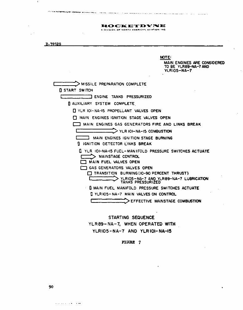
a DIvI*O N oF NoRVI. AMKfICAN AVIATION INC
R-3512S
NOTE:MAIN ENGINES ARE CONSIDEREDTO BE YLR89-NA-7 ANDYLRIO5-NA-7
E2 > MISSILE PREPARATION COMPLETE
0 START SWITCH
E 2 I ENGINE TANKS PRESSURIZED
0 AUXILIARY SYSTEM COMPLETE
o YLR 101- NA-15 PROPELLANT VALVES OPENo- MAIN ENGINES IGNITION STAGE VALVES OPEN
[--' MAIN ENGINES GAS GENERATORS FIRE AND LINKS BREAK
E Z / YLR 101-NA-15 COMBUSTIONMAIN ENGINES IGNITION STAGE BURNING
IGNITION DETECTOR LINKS BREAK
fl YLR 101-NA-15 FUEL-MANIFOLD PRESSURE SWITCHES ACTUATE=: MAINSTAGE CONTROL
C3 MAIN FUEL VALVES OPEN
GAS GENERATORS VALVES OPENQ TRANSITION BURNING (10-90 PERCENT THRUST)S. . YLRI05-NA-7 AND YLR89-NA-7 LUBRICATION
TANKS PRESSURIZEDU MAIN FUEL MANIFOLD PRESSURE SWITCHES ACTUATE
YLR 105- NA-7 MAIN VALVES ON CONTROL
I== EFFECTIVE MAINSTAGE COMBUSTION
STARTING SEQUENCE
YLR89-NA-7, WHEN OPERATED WITHYLRIO5-NA-7 AND YLRIOI-NA-15
FIGURE 7
90

A OIVISiON OF NORT" AM&,CAN ^ViATIQON INC
w
z
Ia~
U) - )W w
VI)
j p U 49
w~~ ~ w 'a 0t
L4 >104lZ W..j w igI z
> 0 0W lb
SU) uL r
0
%2w 0
(I) Z
z IL-
00
w wZ 4 0 0-
> i
z nAflraUU 91
W@m684(e~m e.13

A DIVISION OF NORl4 ^.4ERIC., AV,nON INC
LAUNCHCONTROLPANELS
STATS EANDC INITONETECTOR
SGROUNDGRUDYR9N-&YLI5A-
DC POWERSUPPLY
GROUND MISSILE DISCONNECTS
YLPOINA-15ENGINES
[ENGINE TANKPRESSURE SWITCHES ENGINE YLRIO5-NA-7 YLR89-89-7AND PNEUMATIC RELAY THRUST POWER
REGULATOR HEATER Box CHAMBER PACK
YLR89-NA-7 RIIMA1THRUSTPROPELLANT VALVEI
CHAM BERS CONTROL& ENGINEMISSILE INTERCONNECTING TANK PRESSURIZINGCIRCUITS, INSTRUMENTATION -CONTROLAND DC POWER SUPPLY
POWER CONTROL ARRANGEMENT.YLRIO5-NA-7, WHEN OPERATED WITH
92 YLR89-NA-7 and YLRIOI-NA-IS.FIGURE 9

S R-1452S
ILn
R4
z z
U. 0
II
A w
zIn01
J -- N
9 93
Form 601-5 (V.11w,.) Now. 1-58

A -IISION Or NORTH AMENiCAN AV-VION 4NC
0 0~ ~W UA-
cn Iw-J
, tu
a 0.39
w wz
E~~~ w 44Ir
w > wO
!2.jww w
I 2! ~
Ix x030. 0
94 3

AD.V,0ION or No.,. ANGChhHOA .- ,.VON Nc
__ __ 0
z m~ z
u I0
z
0o mU. ai I.)>c_ Z_
u b- 5 > U
'uzzx 0~At LI le
90
emm~O S V.1w3 R. £

A DIVISION Or NOSITH *MCMCAN AVIATION INC
ILL
-jot
0:a
-0 0 C?
in 0
ii flo/e1 ALkISN30
96
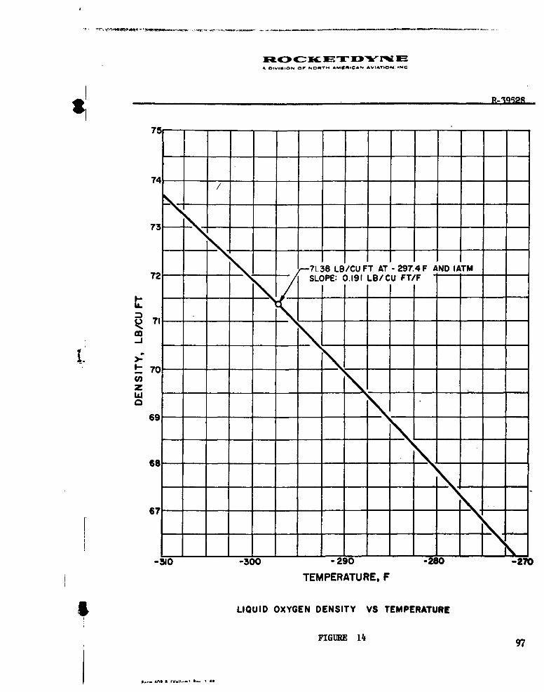
* ,OIVIsloN oP NOW~r f. AME~qeCAN AVIATIroN. INqC
R-191M
73
71.38 LB/CU FT AT -297.4 F AND IATM72- SLOPE: 0.191 LB/CU FT/F
1
t 70Vl)z
9 -
68-----------
67
-310 -300 -290 -280 -270
TEMPERATURE, F
LIQUID OXYGEN DENSITY VS TEMPERATURE
FIGURE 14 97

SOrVISION OW NORTH AMKWICAN AViATiON INC
THE YLRI05-NA-7 THRUST BUILDUPSHALL BE TANGENT TO OR LEFT OFTHE REFERENCE CURVE FOR VALUES OFTHRUST BELOW 45,000 LBS AND TAN-
80 - GENT TO OR RIGHT OF THE REFERENCECURVE FOR VALUES OF THRUST ABOVE.
45,000 LBS.
70
60
0x 50
0
40
1-
30
20
I0'
10
-0.1 0 0.1
TIME IN SECONDS
YLRIOS.NA-7 THRUST BUILDUP SPECIFICATION
ALTITUDES, ZERO TO 10,000 FEET
98 FIGURE 15
F.m . r vWN (1011- b. I.Mll

wa4[ cSI if=-O IP "ORkM A1tWA AV AE~
00 _ _ _ t-.
QD
o 0 m 1 _
x x,
an w
44
I 4
.1
030 ~ ~ ~ ~ 3 231DV3'V~~-
to'. 08.6 vellm) to I.$