Embed Size (px)
Citation preview
24/7 TECHNICAL SUPPORT AT 1.877.877.2269 OR VISIT BLACKBOX.COM
DKM SERIES (CROSS)REPEATERS
USER MANUALACX1M-CC SERIES
Link 1
Link 1
Link 2
Link 2
PRO
G B
A
PRO
G
X
XX
X
2
TABLE OF CONTENTS
NEED HELP?LEAVE THE TECH TO US
LIVE 24/7TECHNICALSUPPORT1.877.877.2269
1.877.877.2269 BLACKBOX.COM
SAFETY INSTRUCTIONS .................................................................................................................................................................. 4Installation ......................................................................................................................................................................................................4Repair ...............................................................................................................................................................................................................4
1. SPECIFICATIONS ........................................................................................................................................................................... 51.1 Interfaces ..................................................................................................................................................................................................5 1.1.1 RJ-45 (Interconnect) ..........................................................................................................................................................................................5 1.1.2 Fiber SFP Type LC (Interconnect) .................................................................................................................................................................... 51.2 Interconnect Cable ...................................................................................................................................................................................5 1.2.1 CATx ....................................................................................................................................................................................................................... 5 1.2.2 Fiber ......................................................................................................................................................................................................................61.3 Connector Pinouts ...................................................................................................................................................................................71.4 Power Supply ............................................................................................................................................................................................81.5 Environmental Conditions .......................................................................................................................................................................81.6 Dimensions ...............................................................................................................................................................................................91.7 Shipping Weight ......................................................................................................................................................................................10
2. DESCRIPTION .............................................................................................................................................................................. 112.1 Application ..............................................................................................................................................................................................112.2 System Overview .................................................................................................................................................................................... 112.3 Product Range ........................................................................................................................................................................................12 2.3.1 Chassis ...............................................................................................................................................................................................................12 2.3.2 (Cross) Repeater Modules ..............................................................................................................................................................................122.4 Accessories Upgrade Kits .....................................................................................................................................................................132.5 Device Views ...........................................................................................................................................................................................14 2.5.1 2-Slot Chassis with One External Power Supply Unit (ACXMODH2-R2) ...........................................................................................14 2.5.2 2-Slot Chassis with One External Power Supply Unit and Redundant Power Option (ACXMODH2R-R2) ................................. 15 2.5.3 2-Slot Chassis with One Internal Power Supply Unit and Redundant Power Option (ACXMODH2R-P-R2) ...............................16 2.5.4 4-Slot Chassis with One External Power Supply Unit (ACXMODH4-R2) ...........................................................................................17 2.5.5 4-Slot Chassis with One External Power Supply Unit and Redundant Power Option (ACXMODH4R-R2) .................................18 2.5.6 6-Slot Chassis with One Internal Power Supply and Redundant Power Option (ACXMODH6R-R2) ...........................................19 2.5.7 6 -Slot Chassis with Active Backplane and Two Internal Power Supplies (ACXMODH6BPAC-R2) .............................................20 2.5.8 6-Slot Chassis with Active Backplane and Two Internal Power Supplies and Connectors on the Back Side (ACXMOD6FPAC-R2) ...................................................................................................................................................21 2.5.9 21-Slot Chassis with One Internal Power Supply and Redundant Power Option (ACXMODH21R)..............................................22 2.5.10 CATx Repeater Module (ACX1M-CC) .........................................................................................................................................................23 2.5.11 Single-Mode Fiber Repeater Module (ACX1M-SS) .................................................................................................................................23 2.5.12 CATx/Single-Mode Fiber Repeater Module (ACX1M-CS) .....................................................................................................................24 2.5.13 CATx Dual Repeater Module (ACX1M-2C2C) ...........................................................................................................................................24 2.5.14 Single-Mode Fiber Dual Repeater Module (ACX1M-2S2S) ...................................................................................................................25 2.5.15 CATx/Single-Mode Fiber Dual Repeater Module (ACX1M-2C2S) .......................................................................................................252.6 Status LEDs ............................................................................................................................................................................................26 2.6.1 Status (Cross) Repeater Module ...................................................................................................................................................................26
3
CHAPTER 1: HEADLINE
1.877.877.2269 BLACKBOX.COM
NEED HELP?LEAVE THE TECH TO US
LIVE 24/7TECHNICALSUPPORT1.877.877.2269
3. INSTALLATION ............................................................................................................................................................................ 273.1 Package Contents ..................................................................................................................................................................................273.2 System Installation ................................................................................................................................................................................27 3.2.1 (Cross) Repeater Setup ...................................................................................................................................................................................273.3 Example Applications ............................................................................................................................................................................283.4 Configuration ..........................................................................................................................................................................................293.5 Operation ................................................................................................................................................................................................29
4. TROUBLESHOOTING ................................................................................................................................................................... 30
5. CONTACTING BLACK BOX TECHNICAL SUPPORT .................................................................................................................. 3151 Support Checklist ....................................................................................................................................................................................315.2 Shipping Checklist .................................................................................................................................................................................31
APPENDIX A. REGULATORY INFORMATION ................................................................................................................................ 32A.1 CE Declaration of Conformity ...............................................................................................................................................................32A.2 FCC Statement .......................................................................................................................................................................................32A.3 Product Safety .......................................................................................................................................................................................32A.4 WEEE .......................................................................................................................................................................................................32A.5 RoHS/RoHS2 ..........................................................................................................................................................................................33A.6 NOM Statement .....................................................................................................................................................................................33
APPENDIX B. GLOSSARY ............................................................................................................................................................... 34
APPENDIX C. DISCLAIMER/TRADEMARKS ................................................................................................................................. 36C.1 Disclaimer ...............................................................................................................................................................................................36C.2 Trademarks Used in this Manual ..........................................................................................................................................................36
4 1.877.877.2269 BLACKBOX.COM
NEED HELP?LEAVE THE TECH TO US
LIVE 24/7TECHNICALSUPPORT1.877.877.2269
SAFETY INSTRUCTIONS
To ensure reliable and safe long-term operation of your Repeater please note the following guidelines.
INSTALLATION
�� Only use in dry, indoor environments.
�� The Repeater and the power supply units can get warm. Do not install components in an enclosed space without any airflow.
�� Do not place the power supply directly on top of the device.
�� Do not obscure ventilation holes.
�� Only use power supplies originally supplied with the product or manufacturer-approved replacements. Do not use a power supply if it appears to be defective or has a damaged chassis.
�� Connect all power supplies to grounded outlets. In each case, ensure that the ground connection is maintained from the outlet socket through to the power supply’s AC power input.
�� Do not connect the link interface to any other equipment, particularly network or telecommunications equipment.
�� Take any required ESD precautions.
NOTE: To disconnect the device completely from the electric circuit, all power cables have to be removed.
REPAIR
�� Do not attempt to open or repair a power supply unit.
�� Do not attempt to open or repair the Repeater. There are no user serviceable parts inside.
�� Please contact Black Box Technical Support at 877-877-2269 or [email protected] if there is a fault.
51.877.877.2269 BLACKBOX.COM
NEED HELP?LEAVE THE TECH TO US
LIVE 24/7TECHNICALSUPPORT1.877.877.2269
CHAPTER 1: SPECIFICATIONS
1.1 INTERFACES
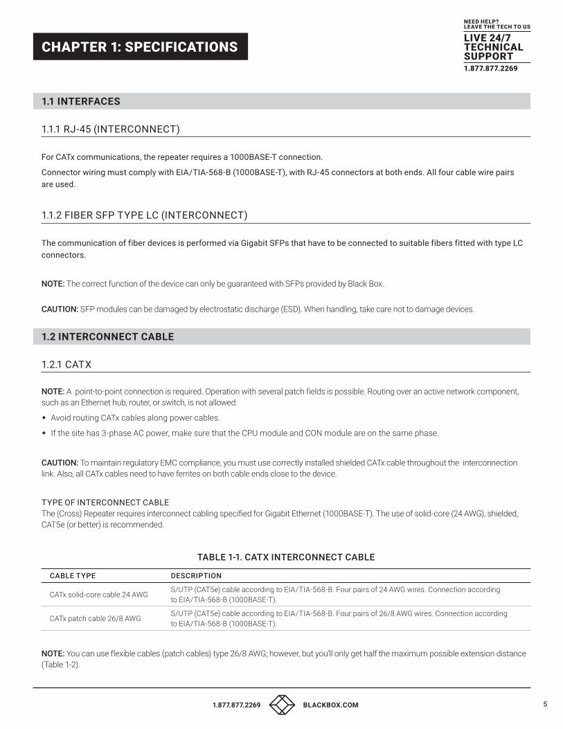
1.1.1 RJ-45 (INTERCONNECT) For CATx communications, the repeater requires a 1000BASE-T connection.
Connector wiring must comply with EIA/TIA-568-B (1000BASE-T), with RJ-45 connectors at both ends. All four cable wire pairs are used.
1.1.2 FIBER SFP TYPE LC (INTERCONNECT) The communication of fiber devices is performed via Gigabit SFPs that have to be connected to suitable fibers fitted with type LC connectors.
NOTE: The correct function of the device can only be guaranteed with SFPs provided by Black Box.
CAUTION: SFP modules can be damaged by electrostatic discharge (ESD). When handling, take care not to damage devices.
1.2 INTERCONNECT CABLE
1.2.1 CATX NOTE: A point-to-point connection is required. Operation with several patch fields is possible. Routing over an active network component, such as an Ethernet hub, router, or switch, is not allowed.
�� Avoid routing CATx cables along power cables.
�� If the site has 3-phase AC power, make sure that the CPU module and CON module are on the same phase.
CAUTION: To maintain regulatory EMC compliance, you must use correctly installed shielded CATx cable throughout the interconnection link. Also, all CATx cables need to have ferrites on both cable ends close to the device.
TYPE OF INTERCONNECT CABLE The (Cross) Repeater requires interconnect cabling specified for Gigabit Ethernet (1000BASE-T). The use of solid-core (24 AWG), shielded, CAT5e (or better) is recommended.
TABLE 1-1. CATX INTERCONNECT CABLE
CABLE TYPE DESCRIPTION
CATx solid-core cable 24 AWGS/UTP (CAT5e) cable according to EIA/TIA-568-B. Four pairs of 24 AWG wires. Connection according to EIA/TIA-568-B (1000BASE-T).
CATx patch cable 26/8 AWGS/UTP (CAT5e) cable according to EIA/TIA-568-B. Four pairs of 26/8 AWG wires. Connection according to EIA/TIA-568-B (1000BASE-T).
NOTE: You can use flexible cables (patch cables) type 26/8 AWG; however, but you’ll only get half the maximum possible extension distance (Table 1-2).
6 1.877.877.2269 BLACKBOX.COM
NEED HELP?LEAVE THE TECH TO US
LIVE 24/7TECHNICALSUPPORT1.877.877.2269
CHAPTER 1: SPECIFICATIONS
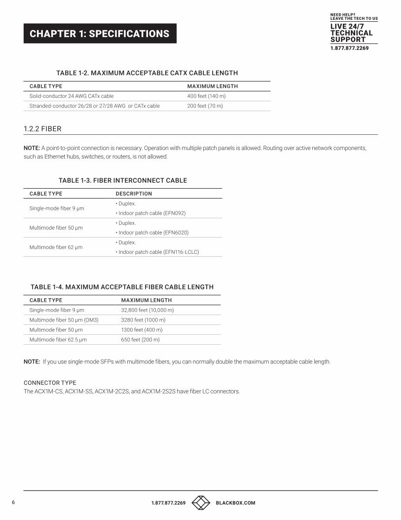
TABLE 1-2. MAXIMUM ACCEPTABLE CATX CABLE LENGTH
CABLE TYPE MAXIMUM LENGTH
Solid-conductor 24 AWG CATx cable 400 feet (140 m)
Stranded-conductor 26/28 or 27/28 AWG or CATx cable 200 feet (70 m)
1.2.2 FIBER NOTE: A point-to-point connection is necessary. Operation with multiple patch panels is allowed. Routing over active network components, such as Ethernet hubs, switches, or routers, is not allowed.
TABLE 1-3. FIBER INTERCONNECT CABLE
CABLE TYPE DESCRIPTION
Single-mode fiber 9 µm• Duplex.
• Indoor patch cable (EFN092)
Multimode fiber 50 µm• Duplex.
• Indoor patch cable (EFN6020)
Multimode fiber 62 µm• Duplex.
• Indoor patch cable (EFN116-LCLC)
TABLE 1-4. MAXIMUM ACCEPTABLE FIBER CABLE LENGTH
CABLE TYPE MAXIMUM LENGTH
Single-mode fiber 9 µm 32,800 feet (10,000 m)
Multimode fiber 50 µm (OM3) 3280 feet (1000 m)
Multimode fiber 50 µm 1300 feet (400 m)
Multimode fiber 62.5 µm 650 feet (200 m)
NOTE: If you use single-mode SFPs with multimode fibers, you can normally double the maximum acceptable cable length.
CONNECTOR TYPE The ACX1M-CS, ACX1M-SS, ACX1M-2C2S, and ACX1M-2S2S have fiber LC connectors.
71.877.877.2269 BLACKBOX.COM
NEED HELP?LEAVE THE TECH TO US
LIVE 24/7TECHNICALSUPPORT1.877.877.2269
CHAPTER 1: SPECIFICATIONS
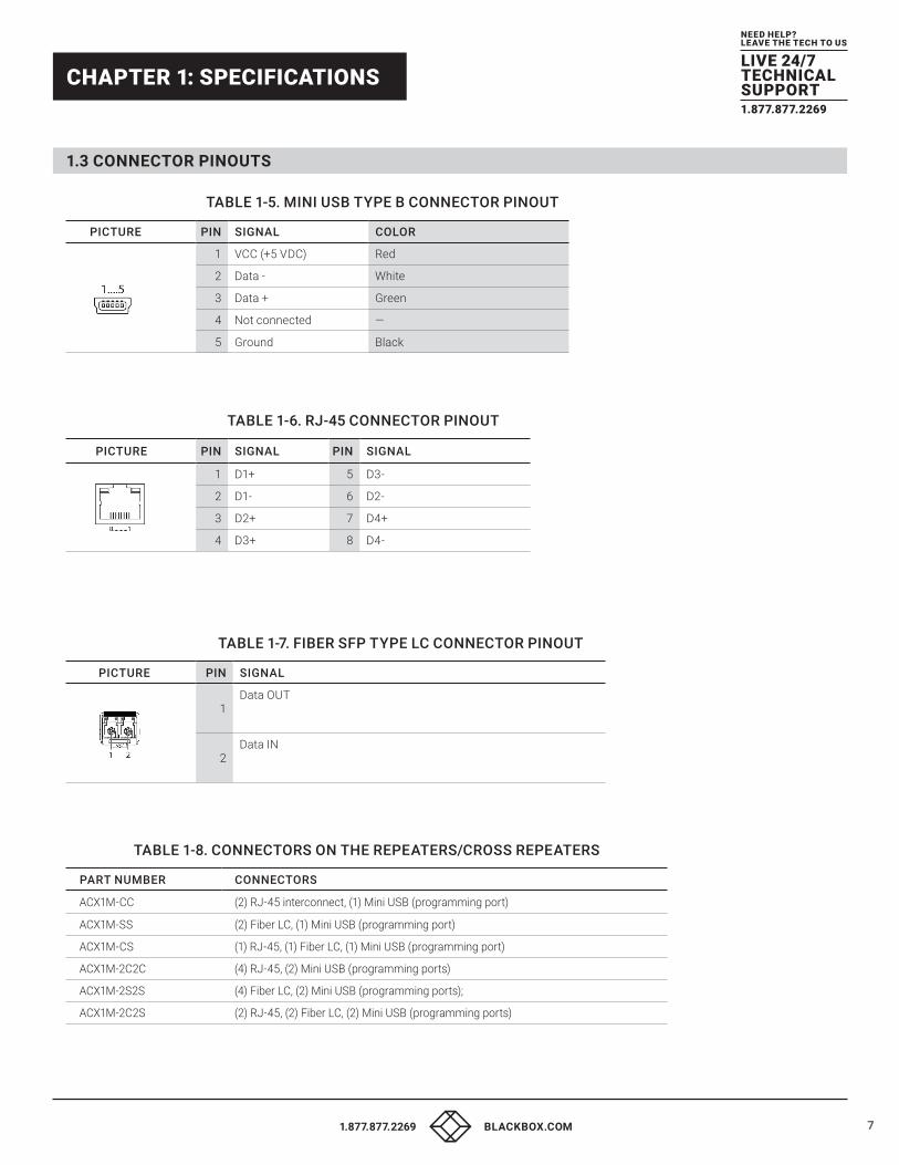
1.3 CONNECTOR PINOUTS
TABLE 1-5. MINI USB TYPE B CONNECTOR PINOUT
PICTURE PIN SIGNAL COLOR
1 VCC (+5 VDC) Red
2 Data - White
3 Data + Green
4 Not connected —
5 Ground Black
TABLE 1-6. RJ-45 CONNECTOR PINOUT
PICTURE PIN SIGNAL PIN SIGNAL
1 D1+ 5 D3-
2 D1- 6 D2-
3 D2+ 7 D4+
4 D3+ 8 D4-
TABLE 1-7. FIBER SFP TYPE LC CONNECTOR PINOUT
PICTURE PIN SIGNAL
1Data OUT
2Data IN
TABLE 1-8. CONNECTORS ON THE REPEATERS/CROSS REPEATERS
PART NUMBER CONNECTORS
ACX1M-CC (2) RJ-45 interconnect, (1) Mini USB (programming port)
ACX1M-SS (2) Fiber LC, (1) Mini USB (programming port)
ACX1M-CS (1) RJ-45, (1) Fiber LC, (1) Mini USB (programming port)
ACX1M-2C2C (4) RJ-45, (2) Mini USB (programming ports)
ACX1M-2S2S (4) Fiber LC, (2) Mini USB (programming ports);
ACX1M-2C2S (2) RJ-45, (2) Fiber LC, (2) Mini USB (programming ports)
8 1.877.877.2269 BLACKBOX.COM
NEED HELP?LEAVE THE TECH TO US
LIVE 24/7TECHNICALSUPPORT1.877.877.2269
CHAPTER 1: SPECIFICATIONS
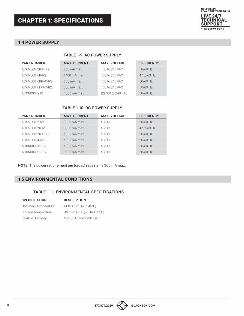
1.4 POWER SUPPLY
TABLE 1-9. AC POWER SUPPLY
PART NUMBER MAX. CURRENT MAX. VOLTAGE FREQUENCY
ACXMODH2R-P-R2 700 mA max. 100 to 240 VAC 50/60 Hz
ACXMODH6R-R2 1400 mA max 100 to 240 VAC 47 to 63 Hz
ACXMODH6BPAC-R2 800 mA max. 100 to 240 VAC 50/60 Hz
ACXMODH6FPAC-R2 800 mA max. 100 to 240 VAC 50/60 Hz
ACXMODH21R 4000 mA max. (2) 100 to 240 VAC 50/60 Hz
TABLE 1-10. DC POWER SUPPLY
PART NUMBER MAX. CURRENT MAX. VOLTAGE FREQUENCY
ACXMODH2-R2 3000 mA max. 5 VDC 50/60 Hz
ACXMODH2R-R2 3000 mA max 5 VDC 47 to 63 Hz
ACXMODH2R-P-R2 5000 mA max. 5 VDC 50/60 Hz
ACXMODH4-R2 5000 mA max. 5 VDC 50/60 Hz
ACXMODH4R-R2 5000 mA max. 5 VDC 50/60 Hz
ACXMODH6R-R2 8000 mA max. 5 VDC 50/60 Hz
NOTE: The power requirement per (cross) repeater is 300 mA max.
1.5 ENVIRONMENTAL CONDITIONS
TABLE 1-11. ENVIRONMENTAL SPECIFICATIONS
SPECIFICATION DESCRIPTION
Operating Temperature 41 to 113° F (5 to 45°C)
Storage Temperature -13 to +140° F (-25 to +60° C)
Relative Humidity Max.80%, noncondensing
91.877.877.2269 BLACKBOX.COM
NEED HELP?LEAVE THE TECH TO US
LIVE 24/7TECHNICALSUPPORT1.877.877.2269
CHAPTER 1: SPECIFICATIONS
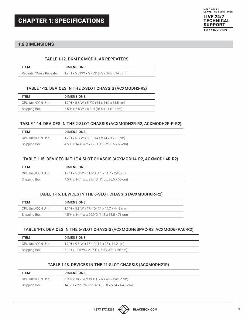
1.6 DIMENSIONS
TABLE 1-12. DKM FX MODULAR REPEATERS
ITEM DIMENSIONS
Repeater/Cross Repeater 1.7”H x 5.81”W x 5.75”D (4.3 x 14.8 x 14.6 cm)
TABLE 1-13. DEVICES IN THE 2-SLOT CHASSIS (ACXMODH2-R2)
ITEM DIMENSIONS
CPU Unit/CON Unit 1.7"H x 5.8"W x 5.7"D (4.1 x 14.7 x 14.5 cm)
Shipping Box 6.5"H x 5.5"W x 8.3"H (16.5 x 14 x 21 cm)
TABLE 1-14. DEVICES IN THE 2-SLOT CHASSIS (ACXMODH2R-R2, ACXMODH2R-P-R2)
ITEM DIMENSIONS
CPU Unit/CON Unit 1.7"H x 5.8"W x 8.3"D (4.1 x 14.7 x 22.1 cm)
Shipping Box 4.5"H x 14.4"W x 21.7"D (11.5 x 36.5 x 55 cm)
TABLE 1-15. DEVICES IN THE 4-SLOT CHASSIS (ACXMODH4-R2, ACXMODH4R-R2)
ITEM DIMENSIONS
CPU Unit/CON Unit 1.7"H x 5.8"W x 11.5"D (4.1 x 14.7 x 29.3 cm)
Shipping Box 4.5"H x 14.4"W x 21.7"D (11.5 x 36.5 x 55 cm)
TABLE 1-16. DEVICES IN THE 6-SLOT CHASSIS (ACXMODH6R-R2)
ITEM DIMENSIONS
CPU Unit/CON Unit 1.7"H x 5.8"W x 17.4"D (4.1 x 14.7 x 44.2 cm)
Shipping Box 4.5"H x 14.4"W x 29.9"D (11.5 x 36.5 x 76 cm)
TABLE 1-17. DEVICES IN THE 6-SLOT CHASSIS (ACXMODH6BPAC-R2, ACXMOD6FPAC-R2)
ITEM DIMENSIONS
CPU Unit/CON Unit 1.7"H x 9.8"W x 17.4"D (4.1 x 25 x 44.2 cm)
Shipping Box 6.1"H x 14.6"W x 21.7"D (15.5 x 37.2 x 55 cm)
TABLE 1-18. DEVICES IN THE 21-SLOT CHASSIS (ACXMODH21R)
ITEM DIMENSIONS
CPU Unit/CON Unit 6.9"H x 18.2"W x 19"D (17.6 x 46.2 x 48.2 cm)
Shipping Box 14.5"H x 22.6"W x 25.4"D (36.8 x 57.4 x 64.5 cm)
10 1.877.877.2269 BLACKBOX.COM
NEED HELP?LEAVE THE TECH TO US
LIVE 24/7TECHNICALSUPPORT1.877.877.2269
CHAPTER 1: SPECIFICATIONS
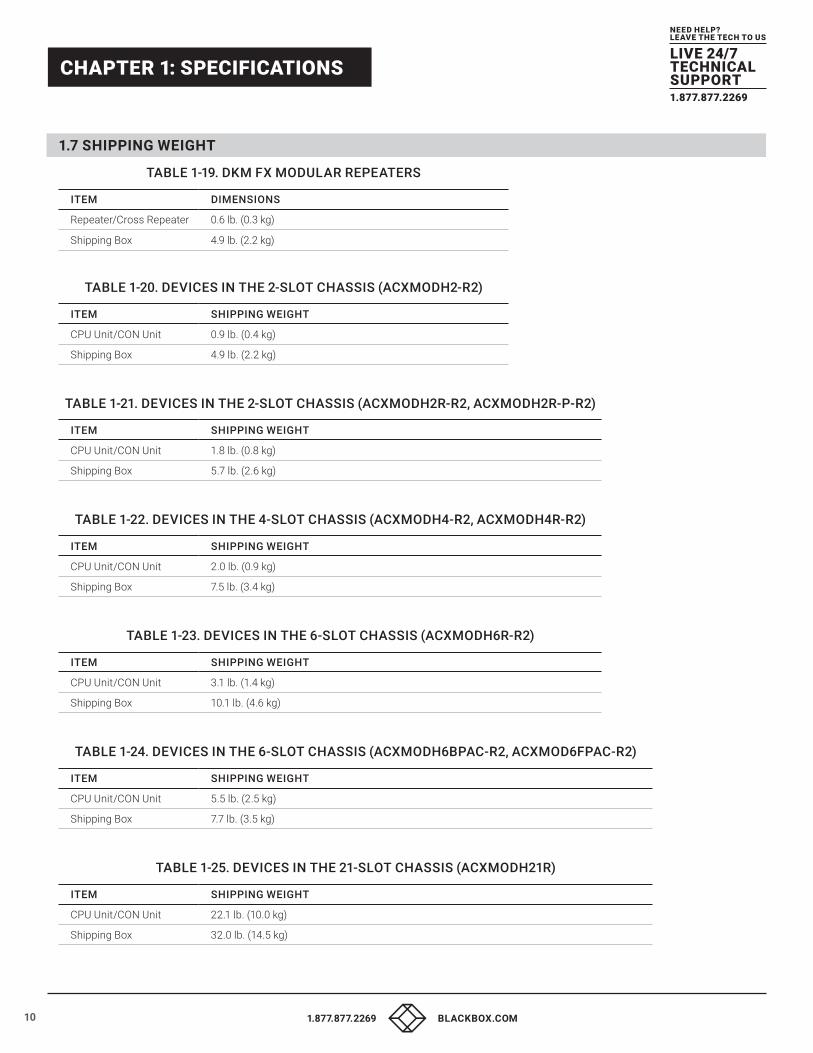
1.7 SHIPPING WEIGHT
TABLE 1-19. DKM FX MODULAR REPEATERS
ITEM DIMENSIONS
Repeater/Cross Repeater 0.6 lb. (0.3 kg)
Shipping Box 4.9 lb. (2.2 kg)
TABLE 1-20. DEVICES IN THE 2-SLOT CHASSIS (ACXMODH2-R2)
ITEM SHIPPING WEIGHT
CPU Unit/CON Unit 0.9 lb. (0.4 kg)
Shipping Box 4.9 lb. (2.2 kg)
TABLE 1-21. DEVICES IN THE 2-SLOT CHASSIS (ACXMODH2R-R2, ACXMODH2R-P-R2)
ITEM SHIPPING WEIGHT
CPU Unit/CON Unit 1.8 lb. (0.8 kg)
Shipping Box 5.7 lb. (2.6 kg)
TABLE 1-22. DEVICES IN THE 4-SLOT CHASSIS (ACXMODH4-R2, ACXMODH4R-R2)
ITEM SHIPPING WEIGHT
CPU Unit/CON Unit 2.0 lb. (0.9 kg)
Shipping Box 7.5 lb. (3.4 kg)
TABLE 1-23. DEVICES IN THE 6-SLOT CHASSIS (ACXMODH6R-R2)
ITEM SHIPPING WEIGHT
CPU Unit/CON Unit 3.1 lb. (1.4 kg)
Shipping Box 10.1 lb. (4.6 kg)
TABLE 1-24. DEVICES IN THE 6-SLOT CHASSIS (ACXMODH6BPAC-R2, ACXMOD6FPAC-R2)
ITEM SHIPPING WEIGHT
CPU Unit/CON Unit 5.5 lb. (2.5 kg)
Shipping Box 7.7 lb. (3.5 kg)
TABLE 1-25. DEVICES IN THE 21-SLOT CHASSIS (ACXMODH21R)
ITEM SHIPPING WEIGHT
CPU Unit/CON Unit 22.1 lb. (10.0 kg)
Shipping Box 32.0 lb. (14.5 kg)
111.877.877.2269 BLACKBOX.COM
NEED HELP?LEAVE THE TECH TO US
LIVE 24/7TECHNICALSUPPORT1.877.877.2269
CHAPTER 2: DESCRIPTION
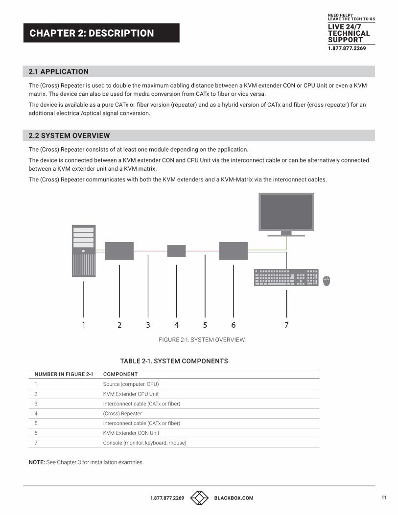
2.1 APPLICATION The (Cross) Repeater is used to double the maximum cabling distance between a KVM extender CON or CPU Unit or even a KVM matrix. The device can also be used for media conversion from CATx to fiber or vice versa.
The device is available as a pure CATx or fiber version (repeater) and as a hybrid version of CATx and fiber (cross repeater) for an additional electrical/optical signal conversion.
2.2 SYSTEM OVERVIEW The (Cross) Repeater consists of at least one module depending on the application.
The device is connected between a KVM extender CON and CPU Unit via the interconnect cable or can be alternatively connected between a KVM extender unit and a KVM matrix.
The (Cross) Repeater communicates with both the KVM extenders and a KVM-Matrix via the interconnect cables.
FIGURE 2-1. SYSTEM OVERVIEW
TABLE 2-1. SYSTEM COMPONENTS
NUMBER IN FIGURE 2-1 COMPONENT
1 Source (computer, CPU)
2 KVM Extender CPU Unit
3 Interconnect cable (CATx or fiber)
4 (Cross) Repeater
5 Interconnect cable (CATx or fiber)
6 KVM Extender CON Unit
7 Console (monitor, keyboard, mouse)
NOTE: See Chapter 3 for installation examples.
12 1.877.877.2269 BLACKBOX.COM
NEED HELP?LEAVE THE TECH TO US
LIVE 24/7TECHNICALSUPPORT1.877.877.2269
CHAPTER 2: DESCRIPTION
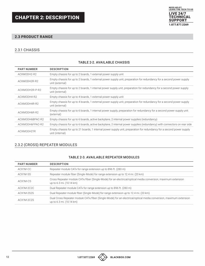
2.3 PRODUCT RANGE
2.3.1 CHASSIS
TABLE 2-2. AVAILABLE CHASSIS
PART NUMBER DESCRIPTION
ACXMODH2-R2 Empty chassis for up to 2 boards, 1 external power supply unit
ACXMODH2R-R2Empty chassis for up to 2 boards, 1 external power supply unit, preparation for redundancy for a second power supply unit (external)
ACXMODH2R-P-R2Empty chassis for up to 2 boards, 1 internal power supply unit, preparation for redundancy for a second power supply unit (external)
ACXMODH4-R2 Empty chassis for up to 4 boards, 1 external power supply unit
ACXMODH4R-R2Empty chassis for up to 4 boards, 1 external power supply unit, preparation for redundancy for a second power supply unit (external)
ACXMODH6R-R2Empty chassis for up to 6 boards, 1 internal power supply, preparation for redundancy for a second power supply unit (external)
ACXMODH6BPAC-R2 Empty chassis for up to 6 boards, active backplane, 2 internal power supplies (redundancy)
ACXMODH6FPAC-R2 Empty chassis for up to 6 boards, active backplane, 2 internal power supplies (redundancy) with connectors on rear side
ACXMODH21REmpty chassis for up to 21 boards, 1 internal power supply unit, preparation for redundancy for a second power supply unit (internal)
2.3.2 (CROSS) REPEATER MODULES
TABLE 2-3. AVAILABLE REPEATER MODULES
PART NUMBER DESCRIPTION
ACX1M-CC Repeater module CATx for range extension up to 896 ft. (280 m)
ACX1M-SS Repeater module fiber (Single-Mode) for range extension up to 12.4 mi. (20 km)
ACX1M-CSCross Repeater module CATx/fiber (Single-Mode) for an electrical/optical media conversion, maximum extension up to 6.3 mi. (10.14 km)
ACX1M-2C2C Dual Repeater module CATx for range extension up to 896 ft. (280 m)
ACX1M-2S2S Dual Repeater module fiber (Single-Mode) for range extension up to 12.4 mi. (20 km)
ACX1M-2C2SDual Cross Repeater module CATx/fiber (Single-Mode) for an electrical/optical media conversion, maximum extension up to 6.3 mi. (10.14 km)
131.877.877.2269 BLACKBOX.COM
NEED HELP?LEAVE THE TECH TO US
LIVE 24/7TECHNICALSUPPORT1.877.877.2269
CHAPTER 2: DESCRIPTION
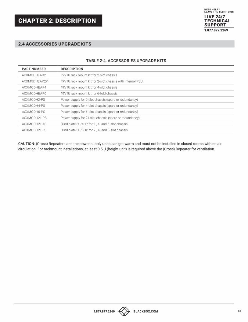
2.4 ACCESSORIES UPGRADE KITS
TABLE 2-4. ACCESSORIES UPGRADE KITS
PART NUMBER DESCRIPTION
ACXMODHEAR2 19”/1U rack mount kit for 2-slot chassis
ACXMODHEAR2P 19”/1U rack mount kit for 2-slot chassis with internal PSU
ACXMODHEAR4 19”/1U rack mount kit for 4-slot chassis
ACXMODHEAR6 19”/1U rack mount kit for 6-fold chassis
ACXMODH2-PS Power supply for 2-slot chassis (spare or redundancy)
ACXMODH4-PS Power supply for 4-slot chassis (spare or redundancy)
ACXMODH6-PS Power supply for 6-slot chassis (spare or redundancy)
ACXMODH21-PS Power supply for 21-slot chassis (spare or redundancy)
ACXMODH21-4S Blind plate 3U/4HP for 2-, 4- and 6-slot chassis
ACXMODH21-8S Blind plate 3U/8HP for 2-, 4- and 6-slot chassis
CAUTION: (Cross) Repeaters and the power supply units can get warm and must not be installed in closed rooms with no air circulation. For rackmount installations, at least 0.5 U (height unit) is required above the (Cross) Repeater for ventilation.
14 1.877.877.2269 BLACKBOX.COM
NEED HELP?LEAVE THE TECH TO US
LIVE 24/7TECHNICALSUPPORT1.877.877.2269
CHAPTER 2: DESCRIPTION
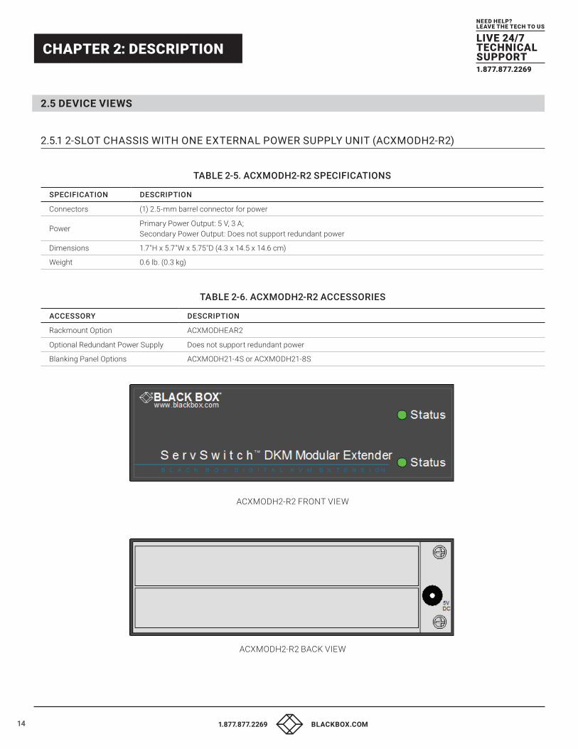
2.5 DEVICE VIEWS
2.5.1 2-SLOT CHASSIS WITH ONE EXTERNAL POWER SUPPLY UNIT (ACXMODH2-R2)
TABLE 2-5. ACXMODH2-R2 SPECIFICATIONS
SPECIFICATION DESCRIPTION
Connectors (1) 2.5-mm barrel connector for power
PowerPrimary Power Output: 5 V, 3 A; Secondary Power Output: Does not support redundant power
Dimensions 1.7"H x 5.7"W x 5.75"D (4.3 x 14.5 x 14.6 cm)
Weight 0.6 lb. (0.3 kg)
TABLE 2-6. ACXMODH2-R2 ACCESSORIES
ACCESSORY DESCRIPTION
Rackmount Option ACXMODHEAR2
Optional Redundant Power Supply Does not support redundant power
Blanking Panel Options ACXMODH21-4S or ACXMODH21-8S
ACXMODH2-R2 FRONT VIEW
ACXMODH2-R2 BACK VIEW
151.877.877.2269 BLACKBOX.COM
NEED HELP?LEAVE THE TECH TO US
LIVE 24/7TECHNICALSUPPORT1.877.877.2269
CHAPTER 2: DESCRIPTION
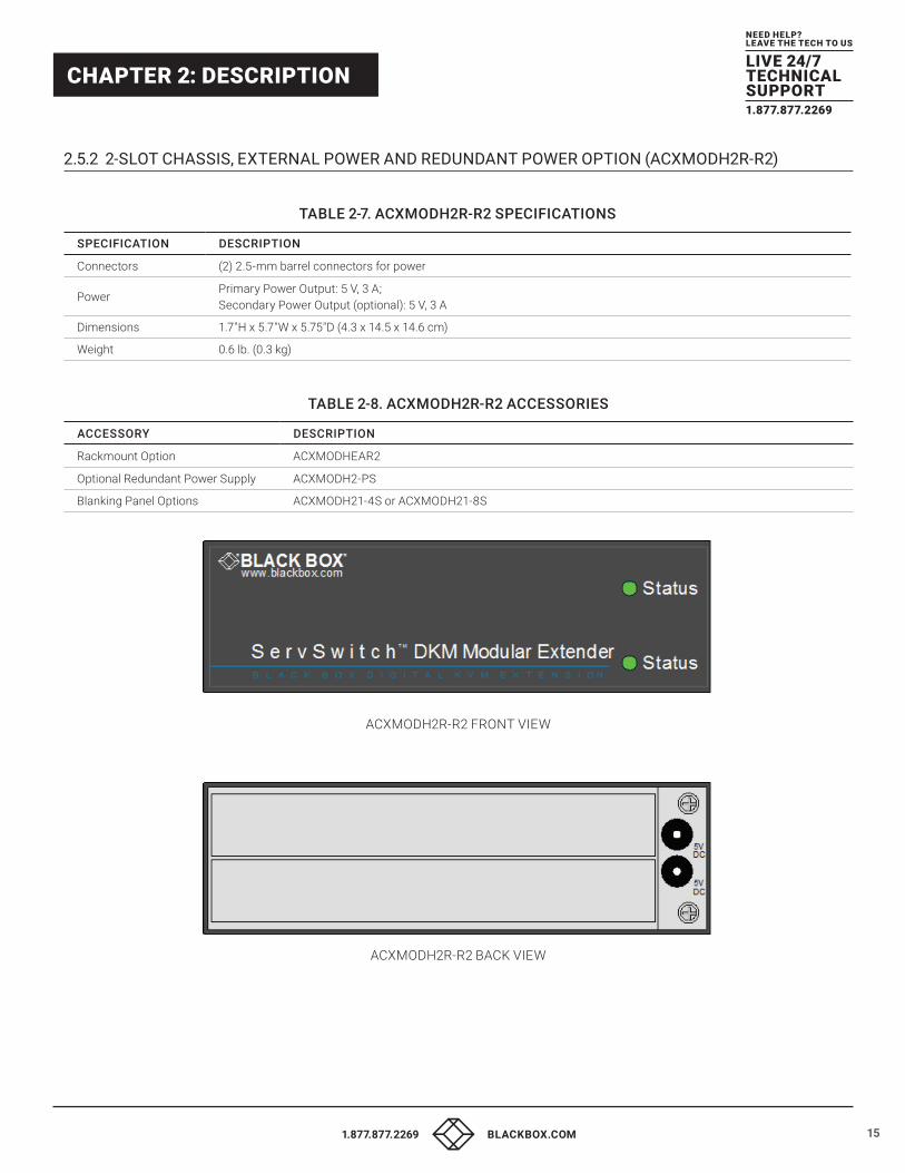
2.5.2 2-SLOT CHASSIS, EXTERNAL POWER AND REDUNDANT POWER OPTION (ACXMODH2R-R2)
TABLE 2-7. ACXMODH2R-R2 SPECIFICATIONS
SPECIFICATION DESCRIPTION
Connectors (2) 2.5-mm barrel connectors for power
PowerPrimary Power Output: 5 V, 3 A; Secondary Power Output (optional): 5 V, 3 A
Dimensions 1.7"H x 5.7"W x 5.75"D (4.3 x 14.5 x 14.6 cm)
Weight 0.6 lb. (0.3 kg)
TABLE 2-8. ACXMODH2R-R2 ACCESSORIES
ACCESSORY DESCRIPTION
Rackmount Option ACXMODHEAR2
Optional Redundant Power Supply ACXMODH2-PS
Blanking Panel Options ACXMODH21-4S or ACXMODH21-8S
ACXMODH2R-R2 FRONT VIEW
ACXMODH2R-R2 BACK VIEW
16 1.877.877.2269 BLACKBOX.COM
NEED HELP?LEAVE THE TECH TO US
LIVE 24/7TECHNICALSUPPORT1.877.877.2269
CHAPTER 2: DESCRIPTION
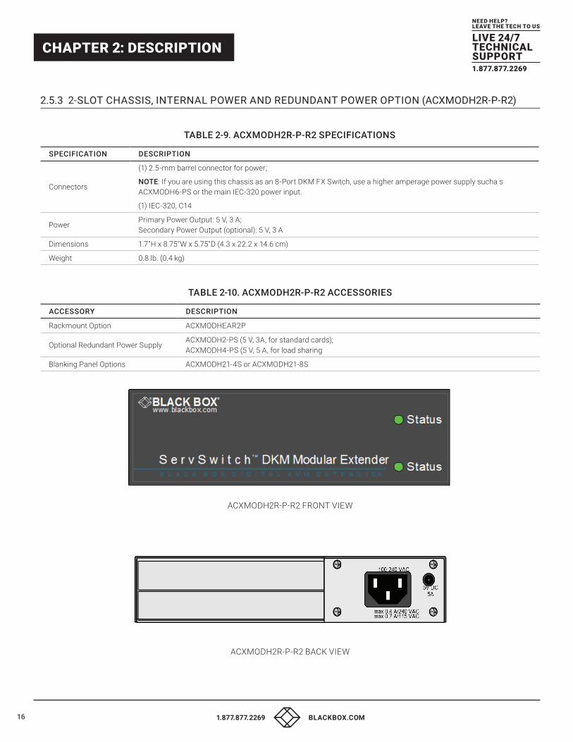
2.5.3 2-SLOT CHASSIS, INTERNAL POWER AND REDUNDANT POWER OPTION (ACXMODH2R-P-R2)
TABLE 2-9. ACXMODH2R-P-R2 SPECIFICATIONS
SPECIFICATION DESCRIPTION
Connectors
(1) 2.5-mm barrel connector for power;
NOTE: If you are using this chassis as an 8-Port DKM FX Switch, use a higher amperage power supply sucha s ACXMODH6-PS or the main IEC-320 power input.
(1) IEC-320, C14
PowerPrimary Power Output: 5 V, 3 A; Secondary Power Output (optional): 5 V, 3 A
Dimensions 1.7"H x 8.75"W x 5.75"D (4.3 x 22.2 x 14.6 cm)
Weight 0.8 lb. (0.4 kg)
TABLE 2-10. ACXMODH2R-P-R2 ACCESSORIES
ACCESSORY DESCRIPTION
Rackmount Option ACXMODHEAR2P
Optional Redundant Power SupplyACXMODH2-PS (5 V, 3A, for standard cards); ACXMODH4-PS (5 V, 5 A, for load sharing
Blanking Panel Options ACXMODH21-4S or ACXMODH21-8S
ACXMODH2R-P-R2 FRONT VIEW
ACXMODH2R-P-R2 BACK VIEW
171.877.877.2269 BLACKBOX.COM
NEED HELP?LEAVE THE TECH TO US
LIVE 24/7TECHNICALSUPPORT1.877.877.2269
CHAPTER 2: DESCRIPTION
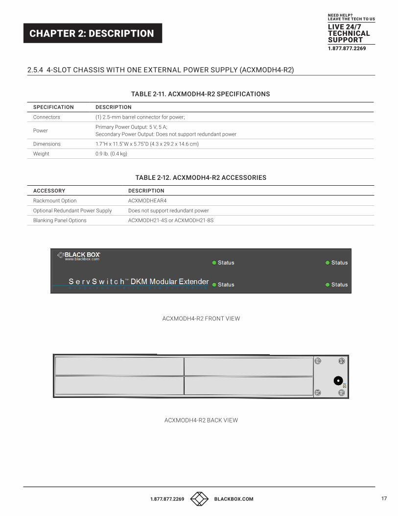
2.5.4 4-SLOT CHASSIS WITH ONE EXTERNAL POWER SUPPLY (ACXMODH4-R2)
TABLE 2-11. ACXMODH4-R2 SPECIFICATIONS
SPECIFICATION DESCRIPTION
Connectors (1) 2.5-mm barrel connector for power;
PowerPrimary Power Output: 5 V, 5 A; Secondary Power Output: Does not support redundant power
Dimensions 1.7"H x 11.5"W x 5.75"D (4.3 x 29.2 x 14.6 cm)
Weight 0.9 lb. (0.4 kg)
TABLE 2-12. ACXMODH4-R2 ACCESSORIES
ACCESSORY DESCRIPTION
Rackmount Option ACXMODHEAR4
Optional Redundant Power Supply Does not support redundant power
Blanking Panel Options ACXMODH21-4S or ACXMODH21-8S
ACXMODH4-R2 FRONT VIEW
ACXMODH4-R2 BACK VIEW

18 1.877.877.2269 BLACKBOX.COM
NEED HELP?LEAVE THE TECH TO US
LIVE 24/7TECHNICALSUPPORT1.877.877.2269
CHAPTER 2: DESCRIPTION
2.5.5 4-SLOT CHASSIS WITH EXTERNAL POWER AND REDUNDANT POWER OPTION (ACXMODH4R-R2)
TABLE 2-13. ACXMODH4R-R2 SPECIFICATIONS
SPECIFICATION DESCRIPTION
Connectors (2) 2.5-mm barrel connectors for power
PowerPrimary Power Output: 5 V, 5 A; Secondary Power Output (Optional): 5 V, 5 A
Dimensions 1.7"H x 11.5"W x 5.75"D (4.3 x 29.2 x 14.6 cm)
Weight 0.9 lb. (0.4 kg)
TABLE 2-14. ACXMODH4R-R2 ACCESSORIES
ACCESSORY DESCRIPTION
Rackmount Option ACXMODHEAR4
Optional Redundant Power Supply ACXMODH4-PS
Blanking Panel Options ACXMODH21-4S or ACXMODH21-8S
ACXMODH4R-R2 FRONT VIEW
ACXMODH4R-R2 BACK VIEW
191.877.877.2269 BLACKBOX.COM
NEED HELP?LEAVE THE TECH TO US
LIVE 24/7TECHNICALSUPPORT1.877.877.2269
CHAPTER 2: DESCRIPTION
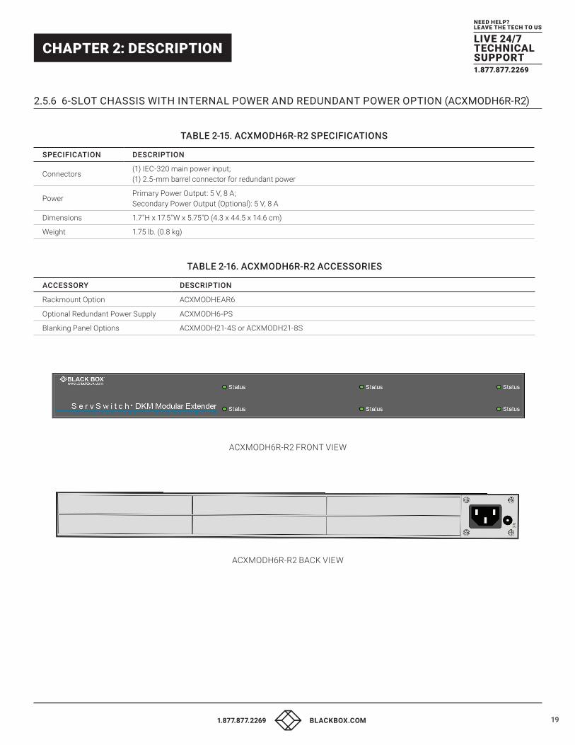
2.5.6 6-SLOT CHASSIS WITH INTERNAL POWER AND REDUNDANT POWER OPTION (ACXMODH6R-R2)
TABLE 2-15. ACXMODH6R-R2 SPECIFICATIONS
SPECIFICATION DESCRIPTION
Connectors(1) IEC-320 main power input; (1) 2.5-mm barrel connector for redundant power
PowerPrimary Power Output: 5 V, 8 A; Secondary Power Output (Optional): 5 V, 8 A
Dimensions 1.7"H x 17.5"W x 5.75"D (4.3 x 44.5 x 14.6 cm)
Weight 1.75 lb. (0.8 kg)
TABLE 2-16. ACXMODH6R-R2 ACCESSORIES
ACCESSORY DESCRIPTION
Rackmount Option ACXMODHEAR6
Optional Redundant Power Supply ACXMODH6-PS
Blanking Panel Options ACXMODH21-4S or ACXMODH21-8S
ACXMODH6R-R2 FRONT VIEW
ACXMODH6R-R2 BACK VIEW
20 1.877.877.2269 BLACKBOX.COM
NEED HELP?LEAVE THE TECH TO US
LIVE 24/7TECHNICALSUPPORT1.877.877.2269
CHAPTER 2: DESCRIPTION
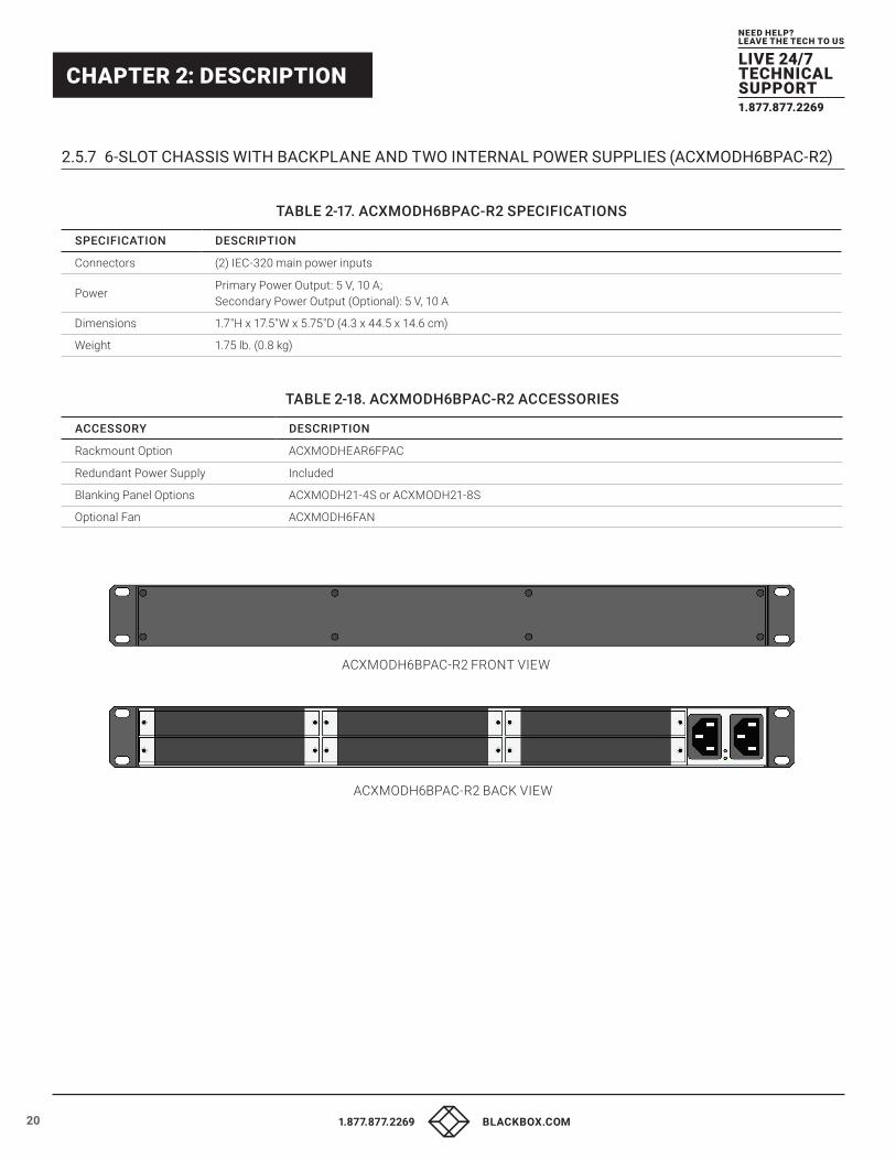
2.5.7 6-SLOT CHASSIS WITH BACKPLANE AND TWO INTERNAL POWER SUPPLIES (ACXMODH6BPAC-R2)
TABLE 2-17. ACXMODH6BPAC-R2 SPECIFICATIONS
SPECIFICATION DESCRIPTION
Connectors (2) IEC-320 main power inputs
PowerPrimary Power Output: 5 V, 10 A; Secondary Power Output (Optional): 5 V, 10 A
Dimensions 1.7"H x 17.5"W x 5.75"D (4.3 x 44.5 x 14.6 cm)
Weight 1.75 lb. (0.8 kg)
TABLE 2-18. ACXMODH6BPAC-R2 ACCESSORIES
ACCESSORY DESCRIPTION
Rackmount Option ACXMODHEAR6FPAC
Redundant Power Supply Included
Blanking Panel Options ACXMODH21-4S or ACXMODH21-8S
Optional Fan ACXMODH6FAN
ACXMODH6BPAC-R2 BACK VIEW
ACXMODH6BPAC-R2 FRONT VIEW
211.877.877.2269 BLACKBOX.COM
NEED HELP?LEAVE THE TECH TO US
LIVE 24/7TECHNICALSUPPORT1.877.877.2269
CHAPTER 2: DESCRIPTION
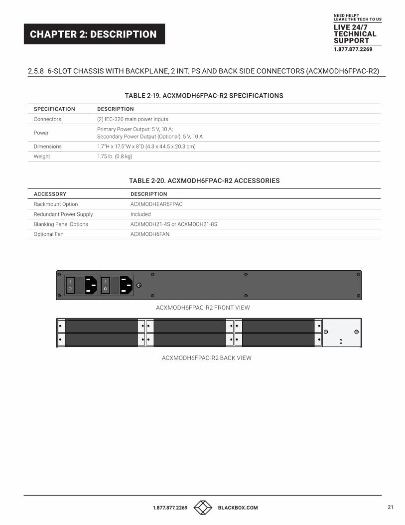
2.5.8 6-SLOT CHASSIS WITH BACKPLANE, 2 INT. PS AND BACK SIDE CONNECTORS (ACXMODH6FPAC-R2)
TABLE 2-19. ACXMODH6FPAC-R2 SPECIFICATIONS
SPECIFICATION DESCRIPTION
Connectors (2) IEC-320 main power inputs
PowerPrimary Power Output: 5 V, 10 A; Secondary Power Output (Optional): 5 V, 10 A
Dimensions 1.7"H x 17.5"W x 8"D (4.3 x 44.5 x 20.3 cm)
Weight 1.75 lb. (0.8 kg)
TABLE 2-20. ACXMODH6FPAC-R2 ACCESSORIES
ACCESSORY DESCRIPTION
Rackmount Option ACXMODHEAR6FPAC
Redundant Power Supply Included
Blanking Panel Options ACXMODH21-4S or ACXMODH21-8S
Optional Fan ACXMODH6FAN
ACXMODH6FPAC-R2 BACK VIEW
ACXMODH6FPAC-R2 FRONT VIEW
22 1.877.877.2269 BLACKBOX.COM
NEED HELP?LEAVE THE TECH TO US
LIVE 24/7TECHNICALSUPPORT1.877.877.2269
CHAPTER 2: DESCRIPTION
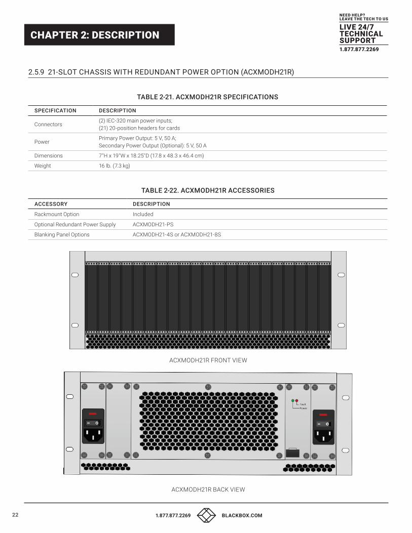
2.5.9 21-SLOT CHASSIS WITH REDUNDANT POWER OPTION (ACXMODH21R)
TABLE 2-21. ACXMODH21R SPECIFICATIONS
SPECIFICATION DESCRIPTION
Connectors(2) IEC-320 main power inputs; (21) 20-position headers for cards
PowerPrimary Power Output: 5 V, 50 A; Secondary Power Output (Optional): 5 V, 50 A
Dimensions 7"H x 19"W x 18.25"D (17.8 x 48.3 x 46.4 cm)
Weight 16 lb. (7.3 kg)
TABLE 2-22. ACXMODH21R ACCESSORIES
ACCESSORY DESCRIPTION
Rackmount Option Included
Optional Redundant Power Supply ACXMODH21-PS
Blanking Panel Options ACXMODH21-4S or ACXMODH21-8S
ACXMODH21R FRONT VIEW
ACXMODH21R BACK VIEW
231.877.877.2269 BLACKBOX.COM
NEED HELP?LEAVE THE TECH TO US
LIVE 24/7TECHNICALSUPPORT1.877.877.2269
CHAPTER 2: DESCRIPTION
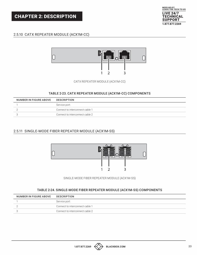
2.5.10 CATX REPEATER MODULE (ACX1M-CC)
CATX REPEATER MODULE (ACX1M-CC)
TABLE 2-23. CATX REPEATER MODULE (ACX1M-CC) COMPONENTS
NUMBER IN FIGURE ABOVE DESCRIPTION
1 Service port
2 Connect to interconnect cable 1
3 Connect to interconnect cable 2
2.5.11 SINGLE-MODE FIBER REPEATER MODULE (ACX1M-SS)
SINGLE-MODE FIBER REPEATER MODULE (ACX1M-SS)
TABLE 2-24. SINGLE-MODE FIBER REPEATER MODULE (ACX1M-SS) COMPONENTS
NUMBER IN FIGURE ABOVE DESCRIPTION
1 Service port
2 Connect to interconnect cable 1
3 Connect to interconnect cable 2
24 1.877.877.2269 BLACKBOX.COM
NEED HELP?LEAVE THE TECH TO US
LIVE 24/7TECHNICALSUPPORT1.877.877.2269
CHAPTER 2: DESCRIPTION
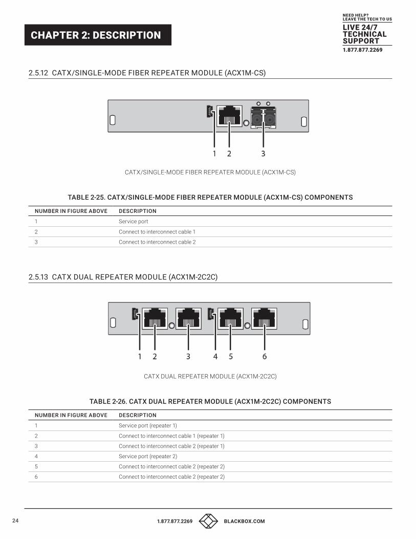
2.5.12 CATX/SINGLE-MODE FIBER REPEATER MODULE (ACX1M-CS)
CATX/SINGLE-MODE FIBER REPEATER MODULE (ACX1M-CS)
TABLE 2-25. CATX/SINGLE-MODE FIBER REPEATER MODULE (ACX1M-CS) COMPONENTS
NUMBER IN FIGURE ABOVE DESCRIPTION
1 Service port
2 Connect to interconnect cable 1
3 Connect to interconnect cable 2
2.5.13 CATX DUAL REPEATER MODULE (ACX1M-2C2C)
CATX DUAL REPEATER MODULE (ACX1M-2C2C)
TABLE 2-26. CATX DUAL REPEATER MODULE (ACX1M-2C2C) COMPONENTS
NUMBER IN FIGURE ABOVE DESCRIPTION
1 Service port (repeater 1)
2 Connect to interconnect cable 1 (repeater 1)
3 Connect to interconnect cable 2 (repeater 1)
4 Service port (repeater 2)
5 Connect to interconnect cable 2 (repeater 2)
6 Connect to interconnect cable 2 (repeater 2)
251.877.877.2269 BLACKBOX.COM
NEED HELP?LEAVE THE TECH TO US
LIVE 24/7TECHNICALSUPPORT1.877.877.2269
CHAPTER 2: DESCRIPTION
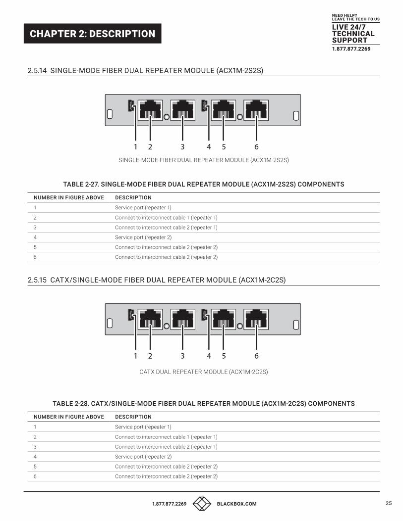
2.5.14 SINGLE-MODE FIBER DUAL REPEATER MODULE (ACX1M-2S2S)
SINGLE-MODE FIBER DUAL REPEATER MODULE (ACX1M-2S2S)
TABLE 2-27. SINGLE-MODE FIBER DUAL REPEATER MODULE (ACX1M-2S2S) COMPONENTS
NUMBER IN FIGURE ABOVE DESCRIPTION
1 Service port (repeater 1)
2 Connect to interconnect cable 1 (repeater 1)
3 Connect to interconnect cable 2 (repeater 1)
4 Service port (repeater 2)
5 Connect to interconnect cable 2 (repeater 2)
6 Connect to interconnect cable 2 (repeater 2)
2.5.15 CATX/SINGLE-MODE FIBER DUAL REPEATER MODULE (ACX1M-2C2S)
CATX DUAL REPEATER MODULE (ACX1M-2C2S)
TABLE 2-28. CATX/SINGLE-MODE FIBER DUAL REPEATER MODULE (ACX1M-2C2S) COMPONENTS
NUMBER IN FIGURE ABOVE DESCRIPTION
1 Service port (repeater 1)
2 Connect to interconnect cable 1 (repeater 1)
3 Connect to interconnect cable 2 (repeater 1)
4 Service port (repeater 2)
5 Connect to interconnect cable 2 (repeater 2)
6 Connect to interconnect cable 2 (repeater 2)
26 1.877.877.2269 BLACKBOX.COM
NEED HELP?LEAVE THE TECH TO US
LIVE 24/7TECHNICALSUPPORT1.877.877.2269
CHAPTER 2: DESCRIPTION
2.6 STATUS LEDS
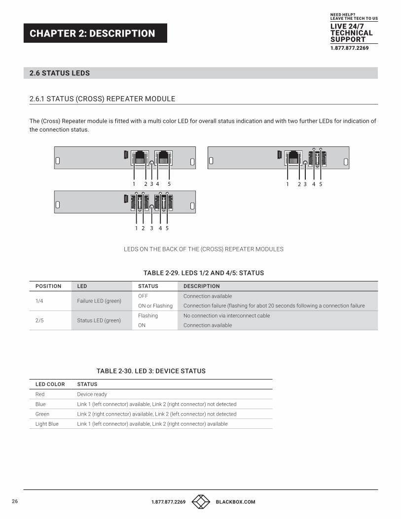
2.6.1 STATUS (CROSS) REPEATER MODULE
The (Cross) Repeater module is fitted with a multi color LED for overall status indication and with two further LEDs for indication of the connection status.
LEDS ON THE BACK OF THE (CROSS) REPEATER MODULES
TABLE 2-29. LEDS 1/2 AND 4/5: STATUS
POSITION LED STATUS DESCRIPTION
1/4 Failure LED (green)OFF
ON or Flashing
Connection available
Connection failure (flashing for abot 20 seconds following a connection failure
2/5 Status LED (green)Flashing
ON
No connection via interconnect cable
Connection available
TABLE 2-30. LED 3: DEVICE STATUS
LED COLOR STATUS
Red Device ready
Blue Link 1 (left connector) available, Link 2 (right connector) not detected
Green Link 2 (right connector) available, Link 2 (left connector) not detected
Light Blue Link 1 (left connector) available, Link 2 (right connector) available
271.877.877.2269 BLACKBOX.COM
NEED HELP?LEAVE THE TECH TO US
LIVE 24/7TECHNICALSUPPORT1.877.877.2269
CHAPTER 3: INSTALLATION
3.1 PACKAGE CONTENTS Your extender package contains the following items:
(Cross) Repeater:
�� (Cross) Repeater in the chassis
�� (1) or (2) 5-VDC international power supply unit(s) per KVM
Extender unit (depending on chassis):
�� (1) or (2) country-specific power cord(s) (depending on chassis)
If anything is missing or damaged, contact Black Box Technical Support at 877-877-2269 or [email protected]
3.2 SYSTEM INSTALLATION First-time users are recommended to setup the system in the same room as a test setup. This will allow you to identify and solve any cabling problems, and experiment with your system more conveniently.
NOTE: Please verify that interconnect cables, interfaces, and handling of the devices comply with the requirements (see Chapter 1).
3.2.1 (CROSS) REPEATER SETUP
1. Switch off all devices.
2. Connect the (Cross) Repeater with the interconnect cable(s).
3. Connect the chassis of the (Cross) Repeater to the power supply.
4. Power up the system.
To power up the system, the following sequence is recommended:
Monitor –> CON Unit –> (Cross) Repeater –> CPU Unit – >source.
28 1.877.877.2269 BLACKBOX.COM
NEED HELP?LEAVE THE TECH TO US
LIVE 24/7TECHNICALSUPPORT1.877.877.2269
CHAPTER 3: INSTALLATION
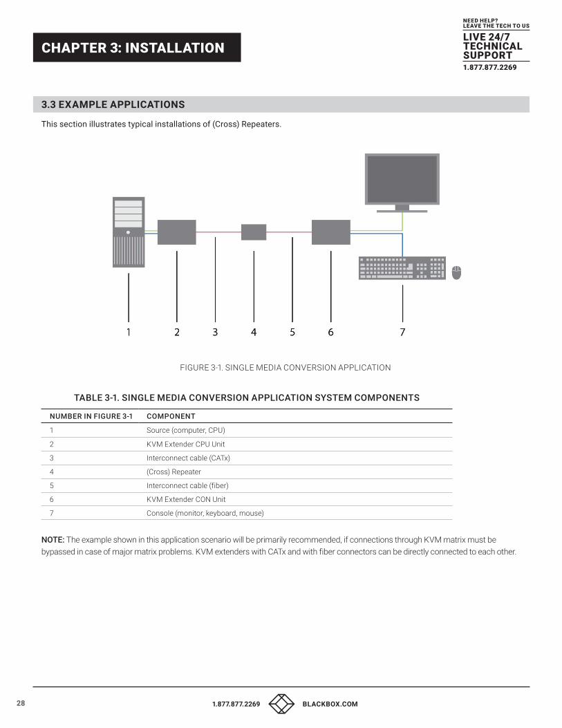
3.3 EXAMPLE APPLICATIONS This section illustrates typical installations of (Cross) Repeaters.
FIGURE 3-1. SINGLE MEDIA CONVERSION APPLICATION
TABLE 3-1. SINGLE MEDIA CONVERSION APPLICATION SYSTEM COMPONENTS
NUMBER IN FIGURE 3-1 COMPONENT
1 Source (computer, CPU)
2 KVM Extender CPU Unit
3 Interconnect cable (CATx)
4 (Cross) Repeater
5 Interconnect cable (fiber)
6 KVM Extender CON Unit
7 Console (monitor, keyboard, mouse)
NOTE: The example shown in this application scenario will be primarily recommended, if connections through KVM matrix must be bypassed in case of major matrix problems. KVM extenders with CATx and with fiber connectors can be directly connected to each other.
291.877.877.2269 BLACKBOX.COM
NEED HELP?LEAVE THE TECH TO US
LIVE 24/7TECHNICALSUPPORT1.877.877.2269
CHAPTER 3: INSTALLATION
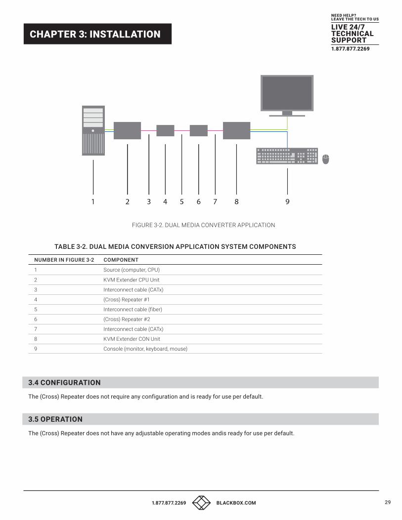
FIGURE 3-2. DUAL MEDIA CONVERTER APPLICATION
TABLE 3-2. DUAL MEDIA CONVERSION APPLICATION SYSTEM COMPONENTS
NUMBER IN FIGURE 3-2 COMPONENT
1 Source (computer, CPU)
2 KVM Extender CPU Unit
3 Interconnect cable (CATx)
4 (Cross) Repeater #1
5 Interconnect cable (fiber)
6 (Cross) Repeater #2
7 Interconnect cable (CATx)
8 KVM Extender CON Unit
9 Console (monitor, keyboard, mouse)
3.4 CONFIGURATION The (Cross) Repeater does not require any configuration and is ready for use per default.
3.5 OPERATION The (Cross) Repeater does not have any adjustable operating modes andis ready for use per default.
30 1.877.877.2269 BLACKBOX.COM
NEED HELP?LEAVE THE TECH TO US
LIVE 24/7TECHNICALSUPPORT1.877.877.2269
CHAPTER 4: TROUBLESHOOTING
GENERAL FAILURES
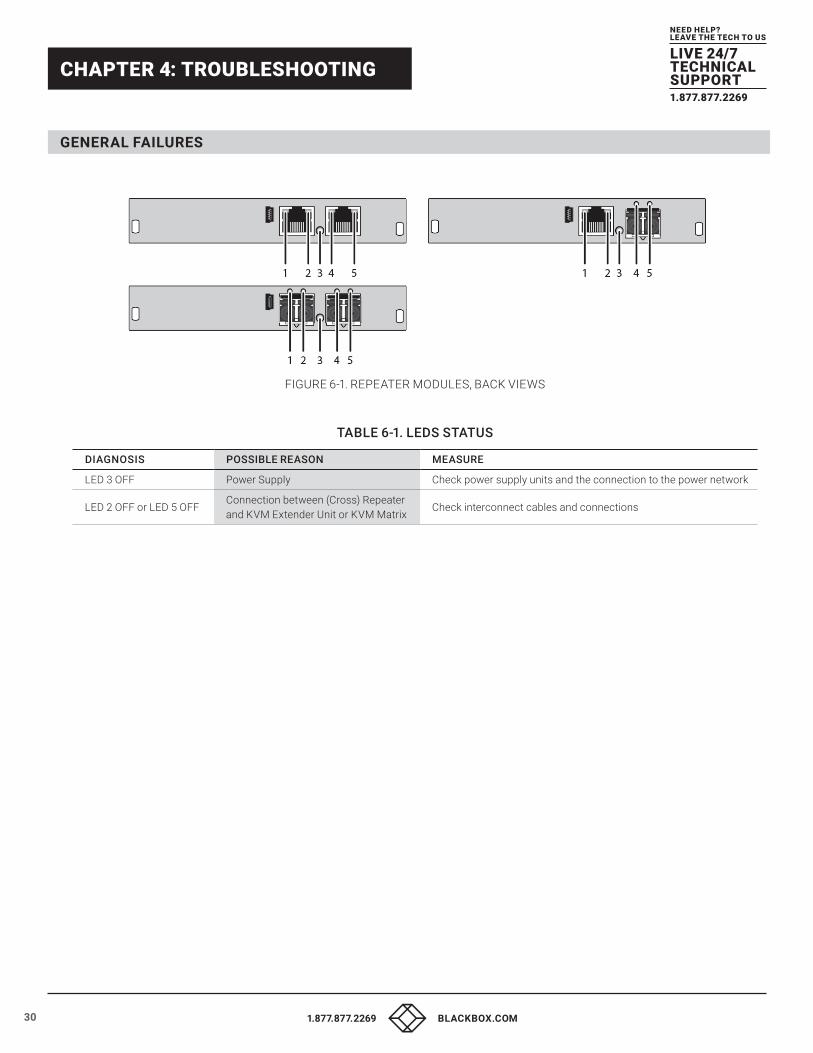
FIGURE 6-1. REPEATER MODULES, BACK VIEWS
TABLE 6-1. LEDS STATUS
DIAGNOSIS POSSIBLE REASON MEASURE
LED 3 OFF Power Supply Check power supply units and the connection to the power network
LED 2 OFF or LED 5 OFFConnection between (Cross) Repeater and KVM Extender Unit or KVM Matrix
Check interconnect cables and connections
311.877.877.2269 BLACKBOX.COM
NEED HELP?LEAVE THE TECH TO US
LIVE 24/7TECHNICALSUPPORT1.877.877.2269
CHAPTER 5: CONTACTING TECHNICAL SUPPORT
5.1 SUPPORT CHECKLIST To efficiently handle your request, make sure that you have the following information available before you call:
�� Company, name, phone number and email
�� Type and serial number of the device (see bottom of device)
�� Date and number of sales receipt, name of dealer if necessary
�� Issue date of the existing manual
�� Nature, circumstances and duration of the problem
�� Components included in the system (such as graphic source/CPU, OS, graphic card, monitor, USB-HID/USB 2.0 devices, interconnect cable) including manufacturer and model number
�� Results from any testing you have done
Contact Black Box Technical Support at 877-877-2269 or [email protected]
5.2 SHIPPING CHECKLIST 1. To return your device, contact Black Box Technical Support at 877-877-2269 or [email protected] to obtain a RMA number
(Return-Material-Authorization).
2. Package your devices carefully, preferably using the original box. Add all pieces that you received originally.
3. Note your RMA number visibly on your shipment. Devices that are sent in without a RMA number cannot be accepted. The shipment will be sent back without being opened, postage unpaid.

32 1.877.877.2269 BLACKBOX.COM
NEED HELP?LEAVE THE TECH TO US
LIVE 24/7TECHNICALSUPPORT1.877.877.2269
APPENDIX A: REGULATORY INFORMATION
A.1 CE DECLARATION OF CONFORMITY These products as delivered comply with the provisions of the following European Directives:
2004/108/EG Council Directive on the approximation of the laws of the Member States relating to electromagnetic compatibility
CE Marking 2009
The products comply with the following harmonized standards for Information Technology Equipment:
�� EN 55022:2010 + A1:2007 (Class A)
�� EN 55024:2010 + A1:2001 + A2:2003
This declaration certifies the conformity to the specified directives but contains no assurance of properties. The safety instructions and installation guidelines noted in this manual shall be considered in detail. Compliance with the specifications for cable lengths and types is mandatory.
Use in a Domestic Environment
This is a Class A product. In a domestic environment, this product may cause radio interference in which case the user may be required to take adequate measures.
A.2 FCC STATEMENT This equipment has been found to comply with the limits for a Class A digital device, pursuant to Part 15 of the FCC Rules. These limits are designed to provide reasonable protection against harmful interference when the equipment is operated in a commercial environment. This equipment generates, uses, and can radiate radio frequency energy and, if not installed and used in accordance with the instruction manual, may cause harmful interference to radio communications. Operation of this equipment in a residential area is likely to cause harmful interference in which case the user will be required to correct the interference at his own expense.
Changes or modifications not expressly approved by the party responsible for compliance could void the user’s authority to operate the equipment.
Shielded cables must be used with this equipment to maintain compliance with radio frequency energy emission regulations and ensure a suitably high level of immunity to electromagnetic disturbances.
All power supplies are certified to the relevant major international safety standards.
A.3 PRODUCT SAFETY The product safety of the devices is proven by the compliance to the following standards:
�� IEC 60950-1A1:2010
�� EN 60950-1/A12:2011
�� UL 60950-1-2007
�� CAN/CSA-C22.2 60950-1-07
A.4 WEEE The manufacturer complies with the EU Directive 2012/19/EU on the prevention of waste electrical and electronic equipment (WEEE). The device labels carry a respective marking.
331.877.877.2269 BLACKBOX.COM
NEED HELP?LEAVE THE TECH TO US
LIVE 24/7TECHNICALSUPPORT1.877.877.2269
APPENDIX A: REGULATORY INFORMATION
A.5 ROHS/ROHS2 This device complies with the Directive 2011/65/EU of the European Parliament and of the council of 8 June 2011 on the restriction of the use of certain hazardous substances in electrical and electronic equipment (RoHS 2, RoHS II).
The device labels carry a respective marking.
A.6 NOM STATEMENT 1. Todas las instrucciones de seguridad y operación deberán ser leídas antes de que el aparato eléctrico sea operado.
2. Las instrucciones de seguridad y operación deberán ser guardadas para referencia futura.
3. Todas las advertencias en el aparato eléctrico y en sus instrucciones de operación deben ser respetadas.
4. Todas las instrucciones de operación y uso deben ser seguidas.
5. El aparato eléctrico no deberá ser usado cerca del agua—por ejemplo, cerca de la tina de baño, lavabo, sótano mojado o cerca de una alberca, etc.
6. El aparato eléctrico debe ser usado únicamente con carritos o pedestales que sean recomendados por el fabricante.
7. El aparato eléctrico debe ser montado a la pared o al techo sólo como sea recomendado por el fabricante.
8. Servicio—El usuario no debe intentar dar servicio al equipo eléctrico más allá a lo descrito en las instrucciones de operación. Todo otro servicio deberá ser referido a personal de servicio calificado.
9. El aparato eléctrico debe ser situado de tal manera que su posición no interfiera su uso. La colocación del aparato eléctrico sobre una cama, sofá, alfombra o superficie similar puede bloquea la ventilación, no se debe colocar en libreros o gabinetes que impidan el flujo de aire por los orificios de ventilación.
10. El equipo eléctrico deber ser situado fuera del alcance de fuentes de calor como radiadores, registros de calor, estufas u otros aparatos (incluyendo amplificadores) que producen calor.
11. El aparato eléctrico deberá ser connectado a una fuente de poder sólo del tipo descrito en el instructivo de operación, o como se indique en el aparato.
12. Precaución debe ser tomada de tal manera que la tierra fisica y la polarización del equipo no sea eliminada.
13. Los cables de la fuente de poder deben ser guiados de tal manera que no sean pisados ni pellizcados por objetos colocados sobre o contra ellos, poniendo particular atención a los contactos y receptáculos donde salen del aparato.
14. El equipo eléctrico debe ser limpiado únicamente de acuerdo a las recomendaciones del fabricante.
15. En caso de existir, una antena externa deberá ser localizada lejos de las lineas de energia.
16. El cable de corriente deberá ser desconectado del cuando el equipo no sea usado por un largo periodo de tiempo.
17. Cuidado debe ser tomado de tal manera que objectos liquidos no sean derramados sobre la cubierta u orificios de ventilación.
18. Servicio por personal calificado deberá ser provisto cuando: A: El cable de poder o el contacto ha sido dañado; u B: Objectos han caído o líquido ha sido derramado dentro del aparato; o C: El aparato ha sido expuesto a la lluvia; o D: El aparato parece no operar normalmente o muestra un cambio en su desempeño; o E: El aparato ha sido tirado o su cubierta ha sido dañada.

34 1.877.877.2269 BLACKBOX.COM
NEED HELP?LEAVE THE TECH TO US
LIVE 24/7TECHNICALSUPPORT1.877.877.2269
APPENDIX B: GLOSSARY
The following terms are commonly used in this guide or in video and KVM technology.
AES/EBU: Digital audio standard that is officially known as AES3 and that is used for carrying digital audio signals between devices.
CATx: Any CAT5e (CAT6, CAT7) cable
CGA: Color Graphics Adapter (CGA) is an old analog graphic standard with up to 16 displayable colors and a maximum resolution of 640 x 400 pixels.
Component Video: Component Video (YPbPr) is a high-quality video standard that consists of three independently and separately transmittable video signals, the luminance signal and two color difference signals.
Composite Video: Composite Video is also called CVBS and it is part of the PAL TV standard.
CON Unit: Component of a KVM Extender or Media Extender to connect to the console (monitor(s), keyboard and mouse; optionally also with USB 2.0 devices)
Console: Keyboard, mouse and monitor
CPU Unit: Component of a KVM Extender or Media Extender to connect to a source (computer, CPU)
CVBS: The analog color video baseband signal (CVBS) is also called Composite Video and it is part of the PAL TV standard.
DDC: Display Data Channel (DDC) is a serial communication interface between monitor and source (computer, CPU). It allows a data exchange via monitor cable and an automatic installation and configuration of a monitor driver by the operating system.
Dual Access: A system to operate a source (computer, CPU) from two consoles
Dual Link: A DVI-D interface for resolutions up to 2560 x 2048 by signal transmission of up to 330 MPixel/s (24-bit)
Dual-Head: A system with two video connections
DVI: Digital video standard, introduced by the Digital Display Working Group (http://www.ddwg.org). Single Link and Dual Link standard are distinguished. The signals have TMDS level.
DVI-D: A DVI-D connector on a graphics card sends out a digital signal only
DVI-I: A combined signal (digital and analog) that allows running a VGA monitor at a DVI-I port—in contrast to DVI-D (see DVI).
EGA: The Enhanced Graphics Adapter (EGA) is an old analog graphic standard, introduced by IBM in 1984. A DB9 connector is used for connection.
Fiber: Single-mode or multi-mode fiber cables
HDMI: An interface for an all-digital transmission of audio and video data. It is differentiated between the HDMI standards 1.0 to 1.4a. The signals have TMDS level.
KVM: Keyboard, video and mouse
Mini-XLR: Industrial standard for electrical plug connections (3-pole) for the transmission of digital audio and control signals
Multi-mode: 62.5μ multi-mode fiber cable or 50μ multi-mode fiber cable
OSD: The On-Screen-Display is used to display information or to operate a device.
Quad-Head: A system with four video connections
RCA (Cinch): A non-standard plug connection for transmission of electrical audio and video signals, especially with coaxial cables
S/PDIF: A digital audio interconnect that is used in consumer audio equipment over relatively short distances.
SFP: SFPs (Small Form Factor Pluggable) are pluggable interface modules for Gigabit connections. SFP modules are available for CATx and fiber interconnect cables.
Single Link: A DVI-D interface for resolutions up to 1920 x 1200 by signal transmission of up to 165 MPixel/s (24-bit). Alternative frequencies are Full HD (1080p), 2K HD (2048 x 1080) and 2048 x 1152.

351.877.877.2269 BLACKBOX.COM
NEED HELP?LEAVE THE TECH TO US
LIVE 24/7TECHNICALSUPPORT1.877.877.2269
APPENDIX B: GLOSSARY
Single-Head: A system with one video connection
Single-mode: 9μ single-mode fiber cable
S-Video (Y/C): S-Video (Y/C) is a video format transmitting luminance and chrominance signals separately. It has a higher quality standard than CVBS.
TOSLINK: Standardized fiber connection system for digital transmission of audio signals (F05 plug connection)
Triple-Head: A system with three video connections
USB-HID: USB-HID devices (Human Interface Devices) allow for data input. There is no need for a special driver during installation; “New USB-HID device found” is reported. Typical HID devices include keyboards, mice, graphics tablets and touch screens. Storage, video and audio devices are not HID.
VGA: Video Graphics Array (VGA) is a computer graphics standard with a typical resolution of 640 x 480 pixels and up to 262,144 colors. It can be seen as a follower of the graphics standards MDA, CGA and EGA.

36 1.877.877.2269 BLACKBOX.COM
NEED HELP?LEAVE THE TECH TO US
LIVE 24/7TECHNICALSUPPORT1.877.877.2269
APPENDIX C: DISCLAIMER/TRADEMARKS
C.1 DISCLAIMER
Black Box Corporation shall not be liable for damages of any kind, including, but not limited to, punitive, consequential or cost of cover damages, resulting from any errors in the product information or specifications set forth in this document and Black Box Corporation may revise this document at any time without notice.
C.2 TRADEMARKS USED IN THIS MANUAL
Black Box and the Black Box logo type and mark are registered trademarks of Black Box Corporation.
Any other trademarks mentioned in this manual are acknowledged to be the property of the trademark owners.

371.877.877.2269 BLACKBOX.COM
NEED HELP?LEAVE THE TECH TO US
LIVE 24/7TECHNICALSUPPORT1.877.877.2269
NOTES
__________________________________________________________________________________________________
__________________________________________________________________________________________________
__________________________________________________________________________________________________
__________________________________________________________________________________________________
__________________________________________________________________________________________________
__________________________________________________________________________________________________
__________________________________________________________________________________________________
_
_________________________________________________________________________________________________
__________________________________________________________________________________________________
__________________________________________________________________________________________________\
__________________________________________________________________________________________________
__________________________________________________________________________________________________
__________________________________________________________________________________________________
__________________________________________________________________________________________________
_________________________________________________________________________________________________
__________________________________________________________________________________________________
__________________________________________________________________________________________________

38 1.877.877.2269 BLACKBOX.COM
NEED HELP?LEAVE THE TECH TO US
LIVE 24/7TECHNICALSUPPORT1.877.877.2269
NOTES
__________________________________________________________________________________________________
__________________________________________________________________________________________________
__________________________________________________________________________________________________
__________________________________________________________________________________________________
__________________________________________________________________________________________________
__________________________________________________________________________________________________
__________________________________________________________________________________________________
_
_________________________________________________________________________________________________
__________________________________________________________________________________________________
__________________________________________________________________________________________________\
__________________________________________________________________________________________________
__________________________________________________________________________________________________
________________________________________________________________________________________________

391.877.877.2269 BLACKBOX.COM
NEED HELP?LEAVE THE TECH TO US
LIVE 24/7TECHNICALSUPPORT1.877.877.2269
NOTES
__
__________________________________________________________________________________________________
_________________________________________________________________________________________________
__________________________________________________________________________________________________
__________________________________________________________________________________________________
__________________________________________________________________________________________________
__________________________________________________________________________________________________
__________________________________________________________________________________________________
__________________________________________________________________________________________________
__________________________________________________________________________________________________
__________________________________________________________________________________________________
__________________________________________________________________________________________________
_
__________________________________________________________________________________________________
_________________________________________________________________________________________________
__________________________________________________________________________________________________
__________________________________________________________________________________________________
__________________________________________________________________________________________________
__________________________________________________________________________________________________
NEED HELP?LEAVE THE TECH TO US
LIVE 24/7TECHNICALSUPPORT1.877.877.2269
© COPYRIGHT 2017 BLACK BOX CORPORATION. ALL RIGHTS RESERVED.