Embed Size (px)
Citation preview
© 2015 Project Lead The Way, Inc. Introduction to Engineering Design Activity 7.4 Assembly Models – Page 1
Activity 7.4 Assembly Models Introduction
Have you ever pieced together a jigsaw puzzle? The individual puzzle pieces have to be rotated and sometimes flipped around. A piece that makes up an outside edge of the puzzle must have its flat edge flush with other pieces of that side. Pieces that have exterior protrusions must be mated to their counterpart interior recesses. The process of putting a jigsaw puzzle together is very similar to building an assembly of components in a CAD program. In this activity you will develop your knowledge of CAD assembly modeling by first practicing on a relatively simple mechanical device called a Jack Lift. This will include performing an interference analysis to determine if any unnecessary overlaps occur between the various components. Next, you will apply your skills to assemble an Automoblox toy vehicle.
Procedure Part I. Use the CAD modeling software to create an assembly of the Jack Lift. You will need access to the five parts of the machine: Base, Wedge, and Wedge Screw. 1. Create a new assembly file titled Jack Lift and save it to your student folder.
2. Place the Base component into the assembly. This component will be grounded
and, therefore, locked in space. Next, place the Wedge and Wedge Screw components into the assembly.
© 2015 Project Lead The Way, Inc. Introduction to Engineering Design Activity 7.4 Assembly Models – Page 2
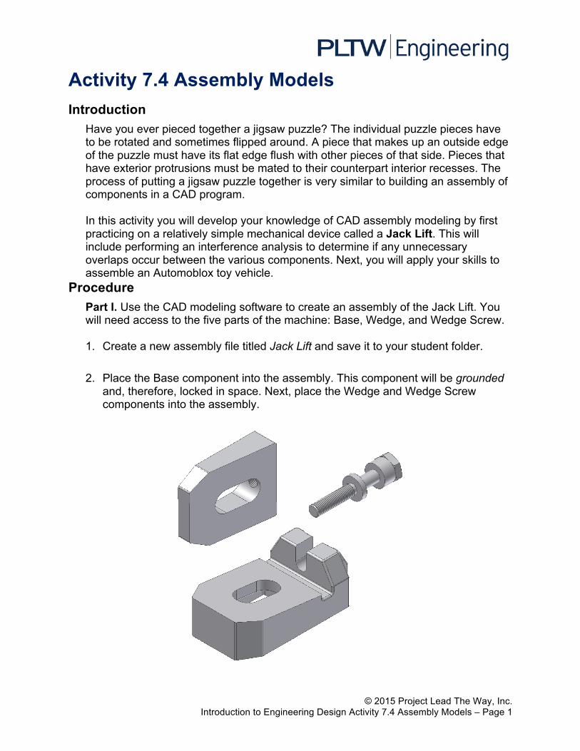
3. Apply a tangent constraint to the neck of the Wedge Screw component (selection shown in blue) and one of the vertical walls of the open slot on the Base component (selection shown in green).
4. Apply a mate constraint to the back face of the Base component (selection shown in blue) and the circular face on the underside of the Wedge Screw’s head.
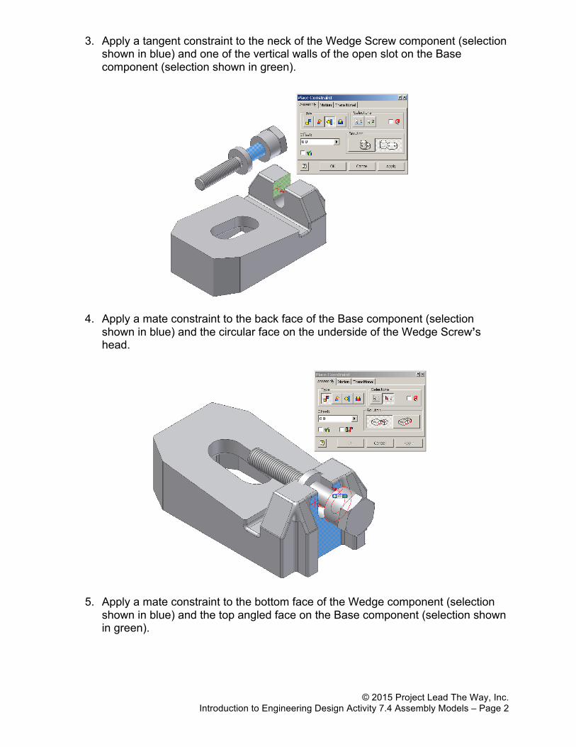
5. Apply a mate constraint to the bottom face of the Wedge component (selection shown in blue) and the top angled face on the Base component (selection shown in green).
© 2015 Project Lead The Way, Inc. Introduction to Engineering Design Activity 7.4 Assembly Models – Page 3
6. Apply a mate constraint between the center axis of the threaded hole in the Wedge component (selection shown in blue) and the center axis of the Wedge Screw component (selection shown in green).
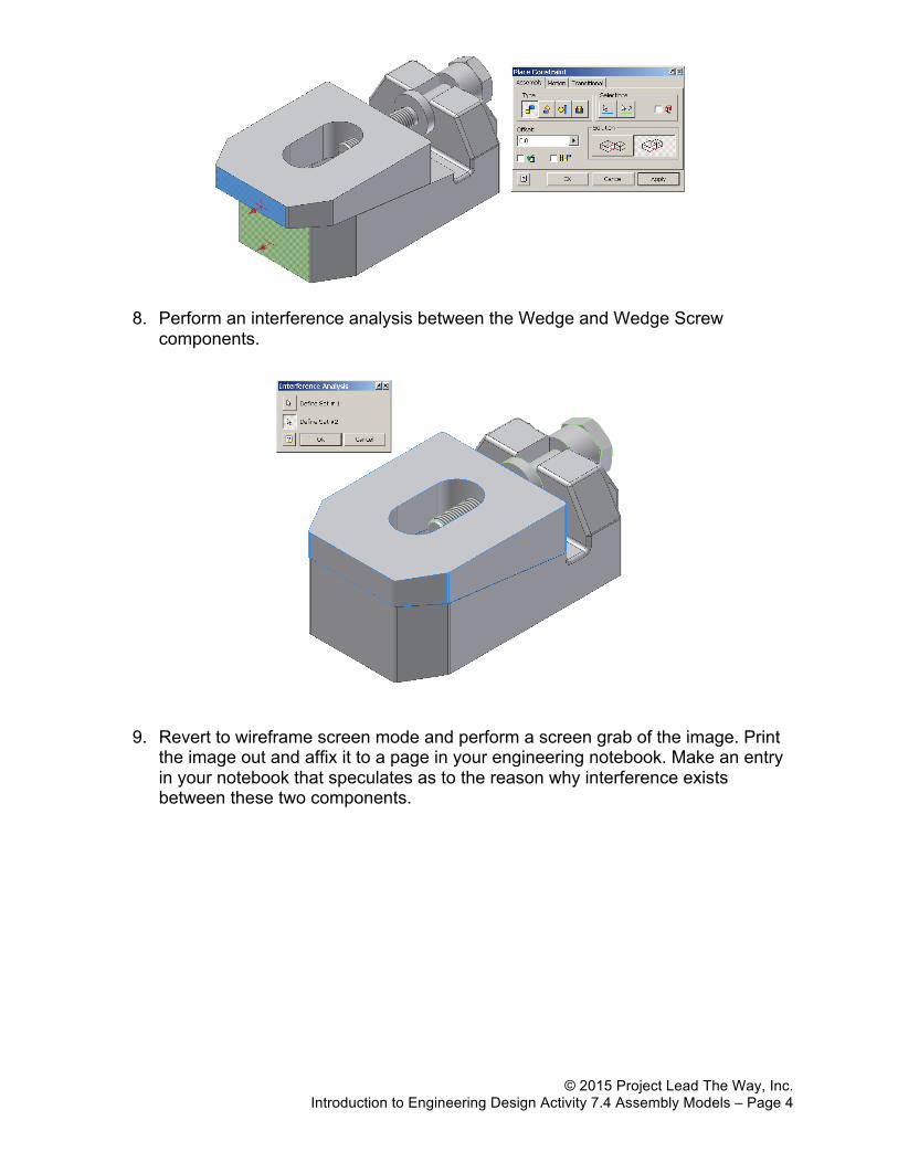
7. Apply a flush constraint to the front faces of the Wedge component (selection shown in blue) and the front face of the Base component (selection shown in green).
© 2015 Project Lead The Way, Inc. Introduction to Engineering Design Activity 7.4 Assembly Models – Page 4
8. Perform an interference analysis between the Wedge and Wedge Screw components.
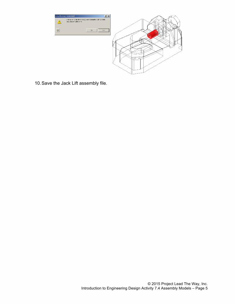
9. Revert to wireframe screen mode and perform a screen grab of the image. Print
the image out and affix it to a page in your engineering notebook. Make an entry in your notebook that speculates as to the reason why interference exists between these two components.
© 2015 Project Lead The Way, Inc. Introduction to Engineering Design Activity 7.4 Assembly Models – Page 5
10. Save the Jack Lift assembly file.