Embed Size (px)
Citation preview
DIAGNOSTYKA’4 (44)/2007
UHL, SZWEDO, Active Thermography And It’s Application For Damage Detection …
77
ACTIVE THERMOGRAPHY AND IT’S APPLICATION FOR DAMAGE
DETECTION IN MECHANICAL STRUCTURE
Tadeusz UHL, Mariusz SZWEDO
Akademia Górniczo-Hutnicza w Krakowie, Katedra Robotyki i Mechatroniki
Al. Mickiewicza 30, +48 12 634 35 05, [email protected]
Summary
Development of measurements techniques helps to apply new more effective tools for damage
detection and localization of damage in composite and metal based structure. One of the most
intensively developing technology is active thermography which can be directly use for damage
detection under operational conditions. The paper presents active thermography techniques,
proposed image processing methods and application of vibrothermography for damage (crack)
detection in aluminum plate. The experimental results confirm high sensitivity of the methods and
its applicability for mechanical structure diagnostics.
Keywords: SHM, NDT, thermography, damage detection, image processing, 2D wavelets analysis.
AKTYWNA TERMOGRAFIA I JEJ WYKORZYSTANIE DO DETEKCJI
USZKODZE STRUKTUR MECHANICZNYCH
Streszczenie
Rozwój technik pomiarowych umo liwia zastosowanie nowych, bardziej efektywnych
narz dzi do detekcji oraz lokalizacji uszkodze w kompozytowych i metalowych strukturach.
Jedn z najbardziej intensywnie rozwijaj cych si technologii jest aktywna termografia, która
mo e zosta u yta bezpo rednio do detekcji uszkodze w trakcie normalnych warunków pracy
urz dzenia. W artykule przedstawiono techniki aktywnej termografii, zaproponowano metod
przetwarzania obrazów termograficznych oraz aplikacj wykorzystuj c wibrotermografi do
detekcji uszkodze dla p yty aluminiowej. Wyniki przeprowadzonego eksperymentu potwierdzaj
wysok czu o metody oraz jej przydatno w diagnostyce.
S owa kluczowe: SHM, NDT, termografia, detekcja uszkodze , przetwarzanie obrazów,
dwuwymiarowa analiza falkowa.
1. INTRODUCTION
Nowadays a reliability of the mechanical
structures is one of the mostly required feature of
many structures like bridges, airplanes, rail vehicles,
and many different industrial installations. Indicated
below structures due to their responsibility should
damage free and should be monitored continuously.
The techniques of the assessment of state of
operating structures are defined as Structural Health
Monitoring (SHM) in the literature [1]. Among
many new methods two main classes can be
distinguished, passive methods and active methods
[1, 2]. In passive methods, the response of the
structure, due to any operation excitations (even not
measured) is under observation. Based on relation of
given signal parameter and its correlation with
a state of the structure the damage can be detected,
localize and sometimes predicted. In active methods
the structure is excited by controlled and measured
excitation using external or build in actuators and
response is measured. Measured response or
estimated based on input and output signals system
characteristics can be a measure of system damage.
One of the most commonly use in SHM method are
methods based on vibration measurements. Within
these methods the symptom based methods and
model based methods are in use, now. In the second
one the measure of the state of the system are
parameters of the model or changes of model
parameters [3]. Many methods which are in use for
SHM are methods which are directly adopted from
the area of Nondestructive Testing (NDT).
Classical NDT methods used during system
operation continuously like acoustic emission
measurements [1], Lambda waves analysis [2],
electromechanical impedance identification [3], are
good examples of SHM oriented techniques. The
difference between NDT and SHM methods is
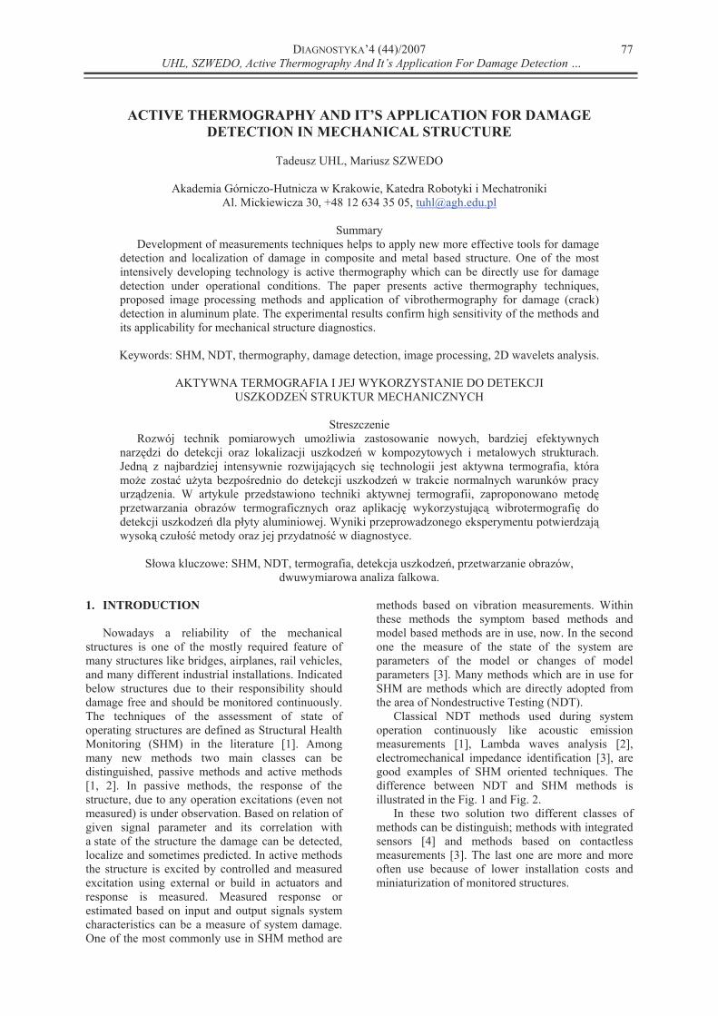
illustrated in the Fig. 1 and Fig. 2.
In these two solution two different classes of
methods can be distinguish; methods with integrated
sensors [4] and methods based on contactless
measurements [3]. The last one are more and more
often use because of lower installation costs and
miniaturization of monitored structures.
DIAGNOSTYKA’4 (44)/2007
UHL, SZWEDO, Active Thermography And It’s Application For Damage Detection …
78
Fig 1 NDT like system
Fig. 2. SHM system
One of the method which can be applied as
active and passive method based on contactless
measurements is the method based on investigation
of thermo-elasticity effect which goes with damage
of the structure (lose structural integrity) like cracks
in metal structures, delamination or disbonding in
composites [5]. The method is under very intensive
development, because thermography techniques are
significantly developed recently [6]. The paper deals
with testing of relation between structural damage
and thermo elastic effect. The pattern recognition
techniques developed by authors are applied to show
sensitivity of the method and its applicability to
detect cracks nucleation and propagation in the
structure.
2. OVERVIEW OF ACTIVE
THERMOGRAPHY TECHNIQUES
Basic theoretical relation employed for dynamic
thermography is formula which describe relation
between changes of strain, stress and changes of
temperature of a body surface [6]:
TE
3)21(
(1)
where: - changes of main strains, – changes of
main stress, - Poisson ratio, T – changes of
temperature, – coefficient of thermal
expansion, E- Young modulus. Assuming
adiabatic transformation (high speed
transformation of stress) the following relation
between changes of strains and changes of
temperature T is valid:
vC
KTT
3 (2)
where: K – compression factor [Pa], C heat
capacity [J/kg K] at constant volume, –
density [kg/m3], T temperature of a body [K].
As the result the formula which approximate
relation between changes of temperature and
changes of stress is obtained in the form:
TKTC
T m
p
(3)
where: Cp heat capacity at constant pressure, Km
thermo elastic constant.
As it can be easily notice from formula (3)
a change of temperature is proportional to changes
of stress. To measure pure stress changes only
temperature should be filtered using common signal
processing procedure as DC component filtering.
DC component filtering can be realized after pattern
capture using special pattern processing technique or
using dedicated technique for frame capturing using
synchronization signal from energy source (thermal
excitation).
The method helps to detect changes in stress
fields due to damage of structure under active test.
The structure should be thermally excited to achieve
stress changes which can be measured using
thermography. Applying the method the damage can
be detected even if have very small dimension
immediately after occurring.
To employ the method effectively the following
conditions should be fulfilled:
1. The structure is loaded with dynamic load with
frequency higher the 3 Hz (all formulas are valid
for adiabatic transformation);
2. The DC component of temperature (T) can be
filtered;
3. The damage occurred on the surface or very
close to surface of a structure
4. Emissivity of the structure is equal or almost
equal on the whole surface of a structure.
Listed above assumptions seriously limit classes
of structure which can be tested using active
thermography in order to detect damages.
Basic assumption in application of active
thermography for SHM is that each structure has
characteristic response for given excitation. In active
thermography several different kind of excitation
can be employed; ultrasound waves, vibrations and
thermal excitation like infrared or microwaves
excitations and other thermal radiation source. The
excitation can have character of short impulse or
continuous harmonic signal The response of the
structure in a form of temperature distribution on
surface which changes during system excitation is
recorded using thermo camera. In the next step of
thermography based SHM procedure the
thermographic pattern of the structure in current
DIAGNOSTYKA’4 (44)/2007
UHL, SZWEDO, Active Thermography And It’s Application For Damage Detection …
79
state is compared with pattern recorded for healthy
system.
Within active thermography four different
techniques can be distinguished which differ each
other by the way of pattern acquisition or pattern
processing.
1) Pulsed Thermography – the source of thermal
excitation are heat impulses with duration from
milliseconds to several seconds. Measurements
of the response during cooling of the surface
helps to avoid disturbances due to radiation of
different heat source in surrounding of structure
under the test. Recorded changes of temperature
distribution and its comparison with the same
temperature distribution for healthy system
allows to assess damage location and damage
dimension.
2) Lock-in Thermography – the source of thermal
excitation In his case is harmonic heat flux.
Reconstruction of the temperature distribution
can be achieved in this method thanks detection
of the amplitude and phase of temperature on a
surface against excitation signal for given
frequency.
3) Step-heating Thermography – the source of
thermal excitation. In his method are short laser
impulses which heat structure locally. The
response in a form of a temperature changes
(increasing) is recorded and process to find
thermal conductivity. The local changes of
thermal conductivity for the structure can help to
detect damage In the structure.
4) Vibrothermography – the source of thermal
excitation is vibration in a frequency range
between 10 Hz till 20 kHz. The thermal response
of the structure due to vibration is heat waves
which are recorded using thermo camera The
damage in a form of composite delamination or
cracking of the structure can be detect based on
measured thermal waves propagation
disturbances. In the vibrothermography the
temperature distribution is measured
synchronically with vibration.
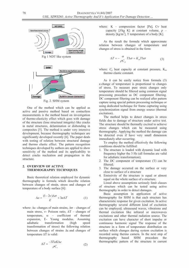
Typical scheme of a measurement system for
vibrothermography of mechanical structures is
shown in Fig. 3.
Fig. 3. Measurements set up for
vibrothermography of mechanical
structures
Due to vibrations the heat is radiated on the
surface of a structure under test. This heat is
generated on the level of micromechanical
phenomena like particle dislocations, friction on
a contact surface of cracks or delaminations of
composites [6]. At vibrating structure in locations of
damages, local deformations of mode shapes are
observed, which can be visualize using thermo
camera. Time history of this deformations recorded
during vibrothermography test is recorded and
analyzed off-line, usually. Heat flux due to structural
vibration depends strongly on frequency range [7, 8,
9]. In practical application of vibrothermography for
SHM, test of sensitivity of the thermal field on the
system surface due to change of excitation frequency
should be done, and for the damage detection this
frequency interval, in which the sensitivity is biggest
has to be chosen. Employing of vibrothermography
require external excitation of structural vibration in
high frequency range (in higher frequency of
vibration, intensity of heat radiation is significantly
bigger then for low frequency) that can be done
using external electromagnetic exciter or using build
in small piezo actuators.
The vibrothermography permits to track changes
in stress distribution directly, but classical active
thermography in principle allows for testing only
changes of thermal conductivity of the structure and
cannot be directly applied for SHM like
vibrothermography.
Authors experiences in application of the
technique indicate that using vibrothermography the
defects located deeper under the structure surface
can be detected then with application of classical
active thermography.
Nowadays many laboratories are intensively
investigate possibilities of application of described
above technologies for SHM purpose.
DIAGNOSTYKA’4 (44)/2007
UHL, SZWEDO, Active Thermography And It’s Application For Damage Detection …
80
3. IMAGE PROCESSING TECHNIQUES
APPLIED FOR THERMOGRAPHY BASED
DAMAGE DETECTION
For damage detection in mechanical structure
using active thermography authors proposed two
steps image processing algorithm. Preprocessing
image analysis Fig. 4, this step provide
normalization of recorded images. Based on
thermographic images non defected and defected
structure, images differences were computed.
Fig. 4. Preprocessing part of defection
detect procedure
This step preparing data for another step of
computation. Normalization image data from
thermographic camera is necessary for proper
correlation of data acquired for destructed and non
destructed structure.
Preprocessed thermographic data let us for
detecting areas of changed thermal energy flow
(strain field).
Second step Fig. 5 established algorithm are
based on wavelet transform for two dimensional
signals.
Fig. 5. Wavelet transform of
preprocessed thermographic images
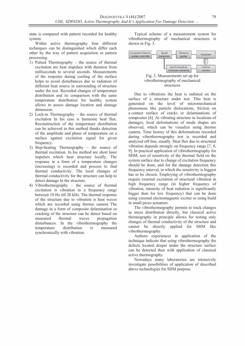
Authors picked up multilevel 2D stationary
wavelet decomposition: sym4 Fig. 6 (orthogonal
wavelet).
This wavelet type were selected experimentally
checking decomposition result for different types of
them. Selected wavelet type gives mostly
representative and wavelet decomposition results
based on this type were best for damaged detection
of the mechanical structure algorithms.
Fig. 6. Sym4 wavelet selected for
decomposition computing
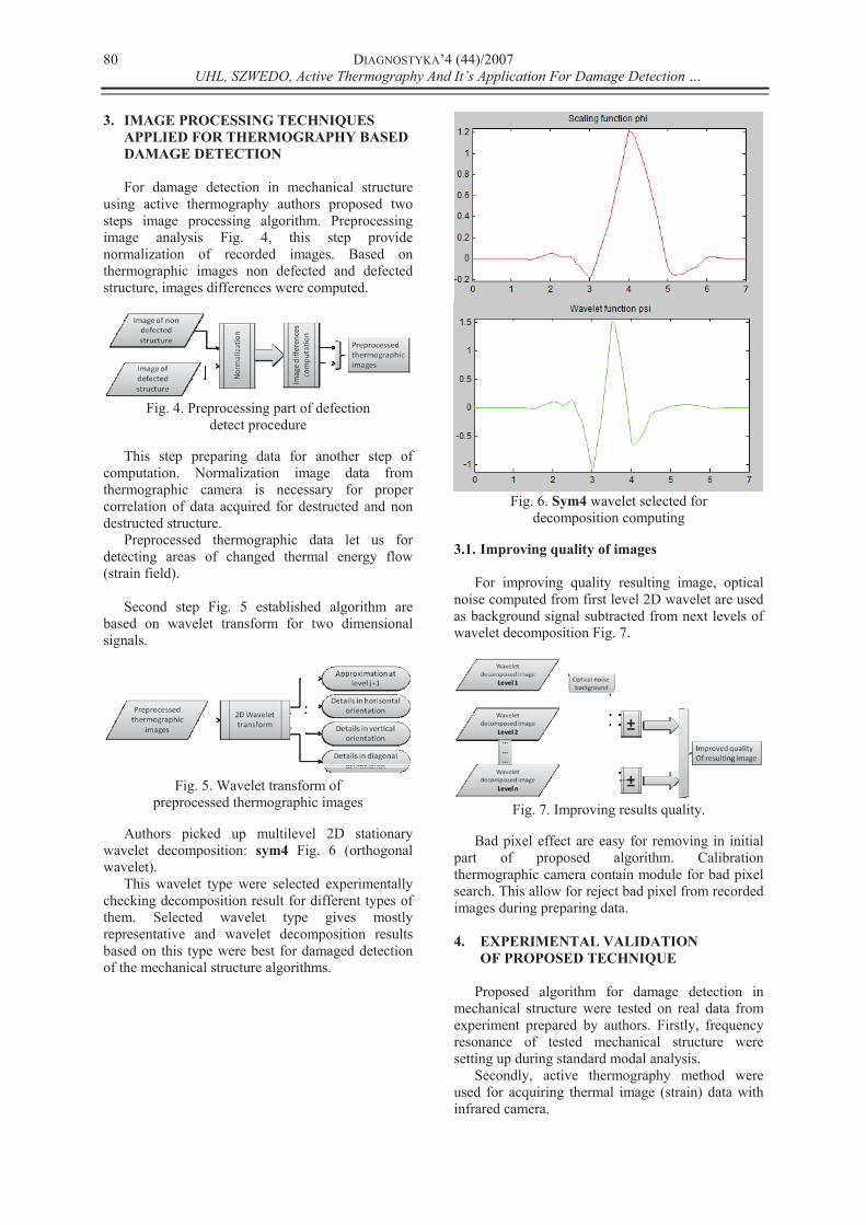
3.1. Improving quality of images
For improving quality resulting image, optical
noise computed from first level 2D wavelet are used
as background signal subtracted from next levels of
wavelet decomposition Fig. 7.
Fig. 7. Improving results quality.
Bad pixel effect are easy for removing in initial
part of proposed algorithm. Calibration
thermographic camera contain module for bad pixel
search. This allow for reject bad pixel from recorded
images during preparing data.
4. EXPERIMENTAL VALIDATION
OF PROPOSED TECHNIQUE
Proposed algorithm for damage detection in
mechanical structure were tested on real data from
experiment prepared by authors. Firstly, frequency
resonance of tested mechanical structure were
setting up during standard modal analysis.
Secondly, active thermography method were
used for acquiring thermal image (strain) data with
infrared camera.
DIAGNOSTYKA’4 (44)/2007
UHL, SZWEDO, Active Thermography And It’s Application For Damage Detection …
81
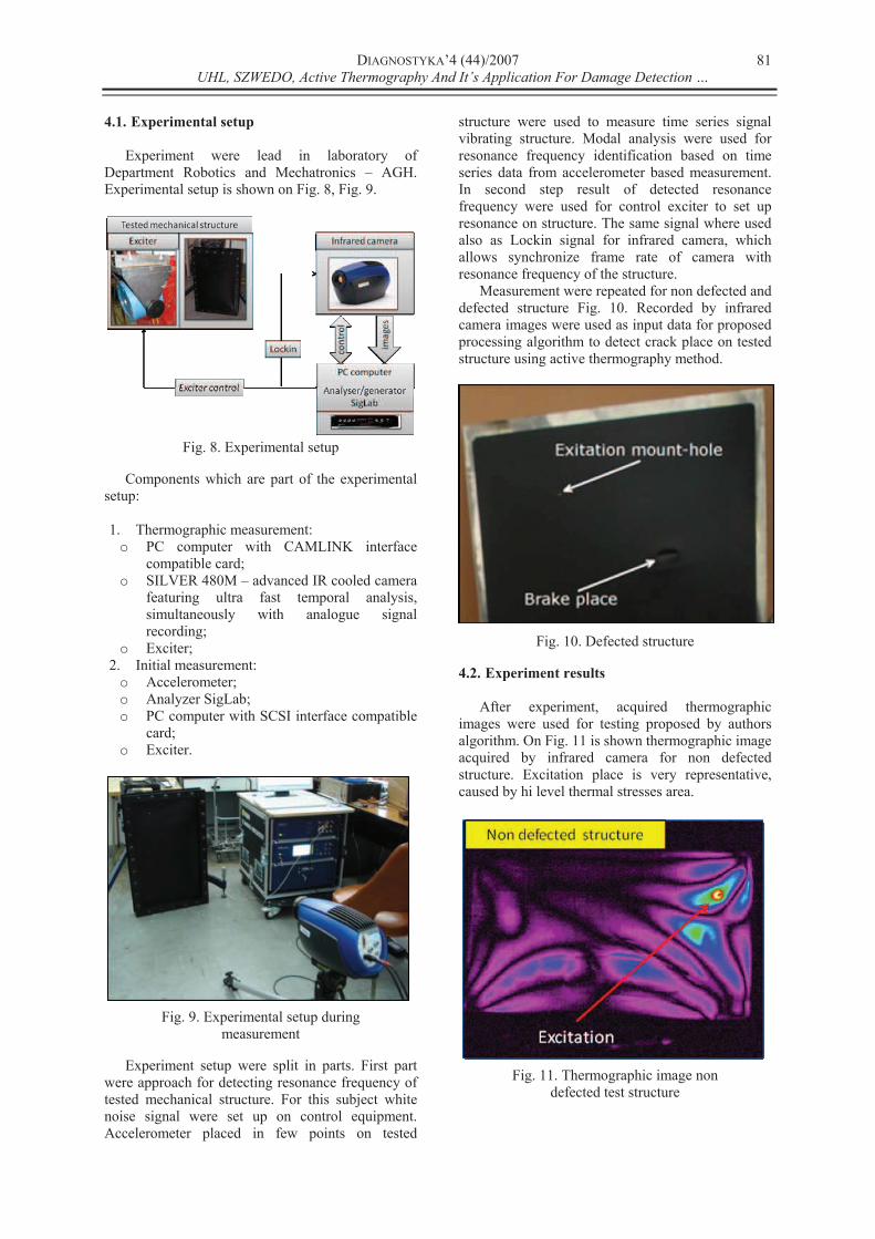
4.1. Experimental setup
Experiment were lead in laboratory of
Department Robotics and Mechatronics – AGH.
Experimental setup is shown on Fig. 8, Fig. 9.
Fig. 8. Experimental setup
Components which are part of the experimental
setup:
1. Thermographic measurement:
o PC computer with CAMLINK interface
compatible card;
o SILVER 480M – advanced IR cooled camera
featuring ultra fast temporal analysis,
simultaneously with analogue signal
recording;
o Exciter;
2. Initial measurement:
o Accelerometer;
o Analyzer SigLab;
o PC computer with SCSI interface compatible
card;
o Exciter.
Fig. 9. Experimental setup during
measurement
Experiment setup were split in parts. First part
were approach for detecting resonance frequency of
tested mechanical structure. For this subject white
noise signal were set up on control equipment.
Accelerometer placed in few points on tested
structure were used to measure time series signal
vibrating structure. Modal analysis were used for
resonance frequency identification based on time
series data from accelerometer based measurement.
In second step result of detected resonance
frequency were used for control exciter to set up
resonance on structure. The same signal where used
also as Lockin signal for infrared camera, which
allows synchronize frame rate of camera with
resonance frequency of the structure.
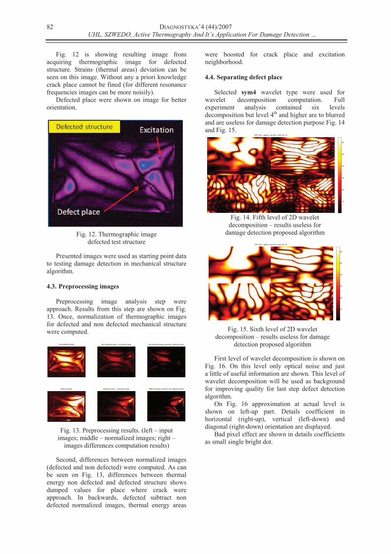
Measurement were repeated for non defected and
defected structure Fig. 10. Recorded by infrared
camera images were used as input data for proposed
processing algorithm to detect crack place on tested
structure using active thermography method.
Fig. 10. Defected structure
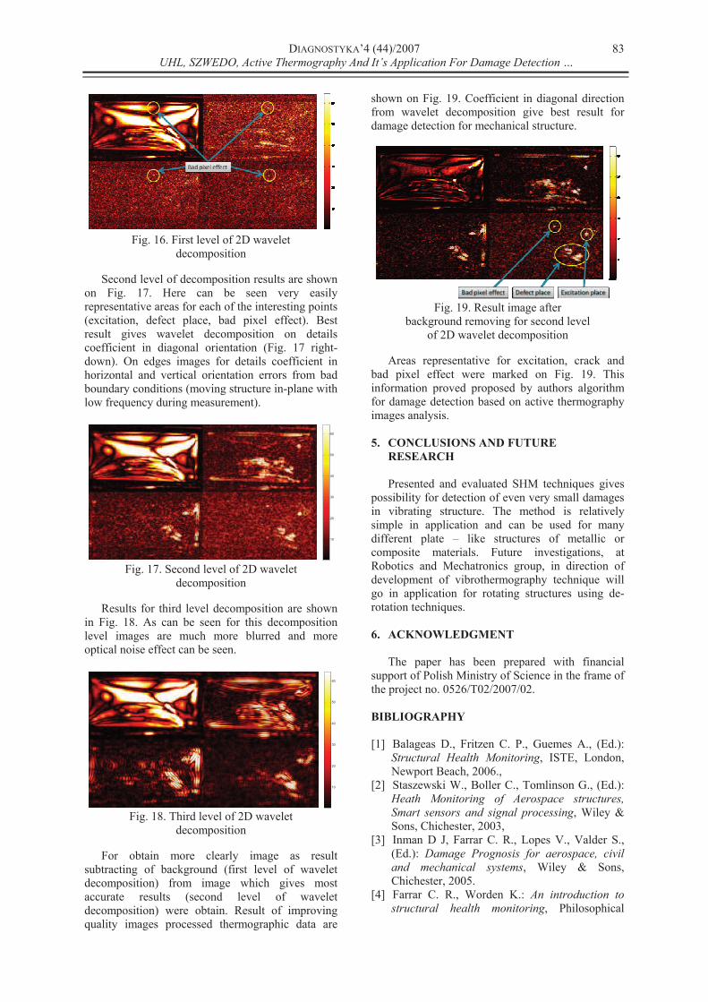
4.2. Experiment results
After experiment, acquired thermographic
images were used for testing proposed by authors
algorithm. On Fig. 11 is shown thermographic image
acquired by infrared camera for non defected
structure. Excitation place is very representative,
caused by hi level thermal stresses area.
Fig. 11. Thermographic image non
defected test structure
DIAGNOSTYKA’4 (44)/2007
UHL, SZWEDO, Active Thermography And It’s Application For Damage Detection …
82
Fig. 12 is showing resulting image from
acquiring thermographic image for defected
structure. Strains (thermal areas) deviation can be
seen on this image. Without any a priori knowledge
crack place cannot be fined (for different resonance
frequencies images can be more noisily).
Defected place were shown on image for better
orientation.
Fig. 12. Thermographic image
defected test structure
Presented images were used as starting point data
to testing damage detection in mechanical structure
algorithm.
4.3. Preprocessing images
Preprocessing image analysis step were
approach. Results from this step are shown on Fig.
13. Once, normalization of thermographic images
for defected and non defected mechanical structure
were computed.
Non defected plate
Defected plate
Non defected plate - normalized data
Defected plate - normalized data
Non defected plate substract Defected plate
Defected plate substract Non defected plate
Fig. 13. Preprocessing results. (left – input
images; middle – normalized images; right –
images differences computation results)
Second, differences between normalized images
(defected and non defected) were computed. As can
be seen on Fig. 13, differences between thermal
energy non defected and defected structure shows
dumped values for place where crack were
approach. In backwards, defected subtract non
defected normalized images, thermal energy areas
were boosted for crack place and excitation
neighborhood.
4.4. Separating defect place
Selected sym4 wavelet type were used for
wavelet decomposition computation. Full
experiment analysis contained six levels
decomposition but level 4th and higher are to blurred
and are useless for damage detection purpose Fig. 14
and Fig. 15. SWT dec.: approx. and det. coefs (lev. 5)
10
20
30
40
50
60
Fig. 14. Fifth level of 2D wavelet
decomposition – results useless for
damage detection proposed algorithm
SWT dec.: approx. and det. coefs (lev. 6)
10
20
30
40
50
60
Fig. 15. Sixth level of 2D wavelet
decomposition – results useless for damage
detection proposed algorithm
First level of wavelet decomposition is shown on
Fig. 16. On this level only optical noise and just
a little of useful information are shown. This level of
wavelet decomposition will be used as background
for improving quality for last step defect detection
algorithm.
On Fig. 16 approximation at actual level is
shown on left-up part. Details coefficient in
horizontal (right-up), vertical (left-down) and
diagonal (right-down) orientation are displayed.
Bad pixel effect are shown in details coefficients
as small single bright dot.
DIAGNOSTYKA’4 (44)/2007
UHL, SZWEDO, Active Thermography And It’s Application For Damage Detection …
83
Fig. 16. First level of 2D wavelet
decomposition
Second level of decomposition results are shown
on Fig. 17. Here can be seen very easily
representative areas for each of the interesting points
(excitation, defect place, bad pixel effect). Best
result gives wavelet decomposition on details
coefficient in diagonal orientation (Fig. 17 right-
down). On edges images for details coefficient in
horizontal and vertical orientation errors from bad
boundary conditions (moving structure in-plane with
low frequency during measurement).
10
20
30
40
50
60
Fig. 17. Second level of 2D wavelet
decomposition
Results for third level decomposition are shown
in Fig. 18. As can be seen for this decomposition
level images are much more blurred and more
optical noise effect can be seen.
10
20
30
40
50
60
Fig. 18. Third level of 2D wavelet
decomposition
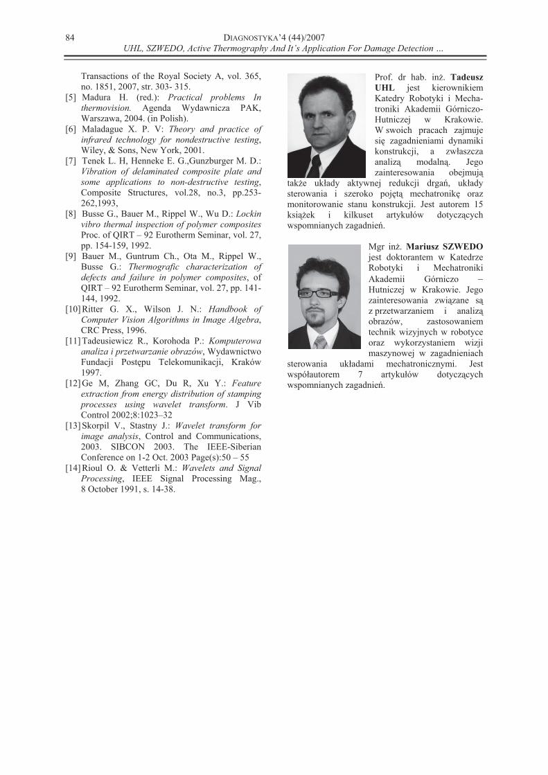
For obtain more clearly image as result
subtracting of background (first level of wavelet
decomposition) from image which gives most
accurate results (second level of wavelet
decomposition) were obtain. Result of improving
quality images processed thermographic data are
shown on Fig. 19. Coefficient in diagonal direction
from wavelet decomposition give best result for
damage detection for mechanical structure.
Fig. 19. Result image after
background removing for second level
of 2D wavelet decomposition
Areas representative for excitation, crack and
bad pixel effect were marked on Fig. 19. This
information proved proposed by authors algorithm
for damage detection based on active thermography
images analysis.
5. CONCLUSIONS AND FUTURE
RESEARCH
Presented and evaluated SHM techniques gives
possibility for detection of even very small damages
in vibrating structure. The method is relatively
simple in application and can be used for many
different plate – like structures of metallic or
composite materials. Future investigations, at
Robotics and Mechatronics group, in direction of
development of vibrothermography technique will
go in application for rotating structures using de-
rotation techniques.
6. ACKNOWLEDGMENT
The paper has been prepared with financial
support of Polish Ministry of Science in the frame of
the project no. 0526/T02/2007/02.
BIBLIOGRAPHY
[1] Balageas D., Fritzen C. P., Guemes A., (Ed.):
Structural Health Monitoring, ISTE, London,
Newport Beach, 2006.,
[2] Staszewski W., Boller C., Tomlinson G., (Ed.):
Heath Monitoring of Aerospace structures,
Smart sensors and signal processing, Wiley &
Sons, Chichester, 2003,
[3] Inman D J, Farrar C. R., Lopes V., Valder S.,
(Ed.): Damage Prognosis for aerospace, civil
and mechanical systems, Wiley & Sons,
Chichester, 2005.
[4] Farrar C. R., Worden K.: An introduction to
structural health monitoring, Philosophical
DIAGNOSTYKA’4 (44)/2007
UHL, SZWEDO, Active Thermography And It’s Application For Damage Detection …
84
Transactions of the Royal Society A, vol. 365,
no. 1851, 2007, str. 303- 315.
[5] Madura H. (red.): Practical problems In
thermovision. Agenda Wydawnicza PAK,
Warszawa, 2004. (in Polish).
[6] Maladague X. P. V: Theory and practice of
infrared technology for nondestructive testing,
Wiley, & Sons, New York, 2001.
[7] Tenek L. H, Henneke E. G.,Gunzburger M. D.:
Vibration of delaminated composite plate and
some applications to non-destructive testing,
Composite Structures, vol.28, no.3, pp.253-
262,1993,
[8] Busse G., Bauer M., Rippel W., Wu D.: Lockin
vibro thermal inspection of polymer composites
Proc. of QIRT – 92 Eurotherm Seminar, vol. 27,
pp. 154-159, 1992.
[9] Bauer M., Guntrum Ch., Ota M., Rippel W.,
Busse G.: Thermografic characterization of
defects and failure in polymer composites, of
QIRT – 92 Eurotherm Seminar, vol. 27, pp. 141-
144, 1992.
[10] Ritter G. X., Wilson J. N.: Handbook of
Computer Vision Algorithms in Image Algebra,
CRC Press, 1996.
[11] Tadeusiewicz R., Korohoda P.: Komputerowa
analiza i przetwarzanie obrazów, Wydawnictwo
Fundacji Post pu Telekomunikacji, Kraków
1997.
[12] Ge M, Zhang GC, Du R, Xu Y.: Feature
extraction from energy distribution of stamping
processes using wavelet transform. J Vib
Control 2002;8:1023–32
[13] Skorpil V., Stastny J.: Wavelet transform for
image analysis, Control and Communications,
2003. SIBCON 2003. The IEEE-Siberian
Conference on 1-2 Oct. 2003 Page(s):50 – 55
[14] Rioul O. & Vetterli M.: Wavelets and Signal
Processing, IEEE Signal Processing Mag.,
8 October 1991, s. 14-38.
Prof. dr hab. in . Tadeusz
UHL jest kierownikiem
Katedry Robotyki i Mecha-
troniki Akademii Górniczo-
Hutniczej w Krakowie.
W swoich pracach zajmuje
si zagadnieniami dynamiki
konstrukcji, a zw aszcza
analiz modaln . Jego
zainteresowania obejmuj
tak e uk ady aktywnej redukcji drga , uk ady
sterowania i szeroko poj t mechatronik oraz
monitorowanie stanu konstrukcji. Jest autorem 15
ksi ek i kilkuset artyku ów dotycz cych
wspomnianych zagadnie .
Mgr in . Mariusz SZWEDO
jest doktorantem w Katedrze
Robotyki i Mechatroniki
Akademii Górniczo
Hutniczej w Krakowie. Jego
zainteresowania zwi zane s
z przetwarzaniem i analiz
obrazów, zastosowaniem
technik wizyjnych w robotyce
oraz wykorzystaniem wizji
maszynowej w zagadnieniach
sterowania uk adami mechatronicznymi. Jest
wspó autorem 7 artyku ów dotycz cych
wspomnianych zagadnie .