Embed Size (px)
Citation preview
Session ____
Proceedings of the 2003 American Society for Engineering Education Annual Conference & Exposition Copyright 2003, American Society for Engineering Education
Active Learning Approaches in Engineering Design Courses
Alan Dutson Brigham Young University – Idaho
Matthew Green and Kristin Wood The University of Texas at Austin
Dan Jensen
United States Air Force Academy
Abstract The pendulum of engineering education is swinging from an emphasis purely on theory to a balance between concrete experiences and analysis. This balance calls for engaging students in active learning through new materials such as hands-on activities, interactive multimedia, and group learning. This balance with concrete experience is especially needed in “building-block” courses that create the foundation for advanced design courses. If we expect students to perform well with open-ended, project-centered problems, we need to provide a pedagogical basis across the entire undergraduate curriculum. This paper presents such a basis for one important engineering core topic: mechanics of materials. Active learning concepts applied in mechanics of materials courses are discussed, including specific examples of hands-on, multimedia, and group design exercises. 1. Introduction One of the needed reformations in engineering education involves a change in instructional methods from passive, lecture-type techniques to more active methods. Pedagogical techniques that involve active participation from students address a wider array of learning styles than traditional lecture-based approaches. Several studies have shown that, not only do students prefer the active approach to learning, but that active learning techniques can enhance the cognitive skills of students more readily than traditional lectures1. The term “active learning” implies an active participation by students in the learning process, as opposed to passively “receiving” information from an instructor during a lecture. Although the concept behind “active learning” is apparent, a precise definition is difficult to find in the literature since many authors differ on the types of activities they consider to be “active.” Some would argue that all learning is “active” by nature (including active “thinking” and note taking in a lecture setting1,2). Most authors, however, consider listening to a lecture or taking notes as “passive” activities3. In this paper we adopt Bonwell’s definition and use the term “active learning” to refer to instructional activities that require students to “engage in such higher-order thinking tasks as analysis, synthesis, and evaluation,” and that involve students “in doing things and thinking about what they are doing” 1 (italics added). A wide array of instructional techniques for implementing active learning is described in the literature. In this paper we focus on three major categories of active learning: (i) hands-on
Page 8.158.1
Proceedings of the 2003 American Society for Engineering Education Annual Conference & Exposition Copyright 2003, American Society for Engineering Education
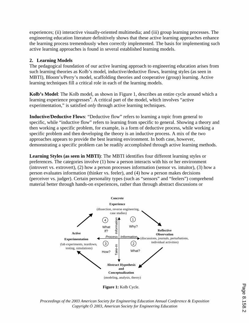
experiences; (ii) interactive visually-oriented multimedia; and (iii) group learning processes. The engineering education literature definitively shows that these active learning approaches enhance the learning process tremendously when correctly implemented. The basis for implementing such active learning approaches is found in several established learning models. 2. Learning Models The pedagogical foundation of our active learning approach to engineering education arises from such learning theories as Kolb’s model, inductive/deductive flows, learning styles (as seen in MBTI), Bloom’s/Perry’s model, scaffolding theories and cooperative (group) learning. Active learning techniques fill a critical role in each of the learning models. Kolb’s Model: The Kolb model, as shown in Figure 1, describes an entire cycle around which a learning experience progresses4. A critical part of the model, which involves “active experimentation,” is satisfied only through active learning techniques. Inductive/Deductive Flows: “Deductive flow” refers to learning a topic from general to specific, while “inductive flow” refers to learning from specific to general. Showing a theory and then working a specific problem, for example, is a form of deductive process, while working a specific problem and then developing the theory is an inductive process. A mix of the two approaches appears to provide the best learning environment. In both case, however, demonstrating a specific problem can be readily accomplished through active learning methods. Learning Styles (as seen in MBTI): The MBTI identifies four different learning styles or preferences. The categories involve (1) how a person interacts with his or her environment (introvert vs. extrovert), (2) how a person processes information (sensor vs. intuitor), (3) how a person evaluates information (thinker vs. feeler), and (4) how a person makes decisions (perceiver vs. judger). Certain personality types (such as “sensors” and “feelers”) comprehend material better through hands-on experiences, rather than through abstract discussions or
Concrete
Experience
Abstract Hypothesisand
Conceptualization
ReflectiveObservationActive
Experimentation
(dissection, reverse engineering, case studies)
(discussions, journals, perturbations, individual activities)
(modeling, analysis, theory)
(lab experiments, teardown, testing, simulations)
1
23
4
Process Information
Tak
e-In
I
nfor
mat
ion
Why?
What?How?
WhatIf?
Figure 1: Kolb Cycle.
Figure 0
Page 8.158.2
Proceedings of the 2003 American Society for Engineering Education Annual Conference & Exposition Copyright 2003, American Society for Engineering Education
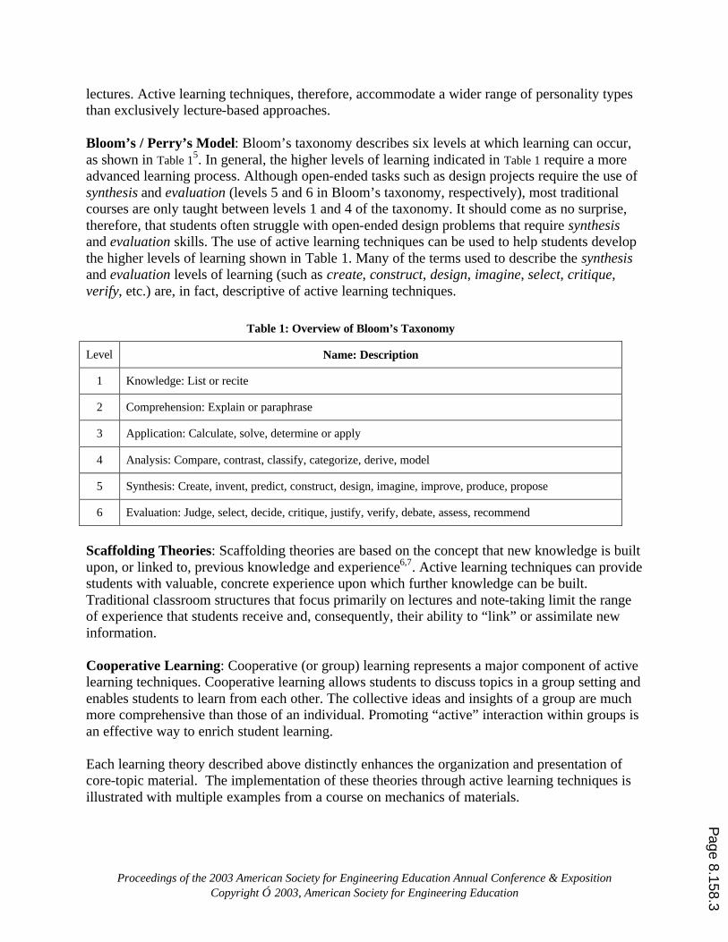
lectures. Active learning techniques, therefore, accommodate a wider range of personality types than exclusively lecture-based approaches. Bloom’s / Perry’s Model: Bloom’s taxonomy describes six levels at which learning can occur, as shown in Table 15. In general, the higher levels of learning indicated in Table 1 require a more advanced learning process. Although open-ended tasks such as design projects require the use of synthesis and evaluation (levels 5 and 6 in Bloom’s taxonomy, respectively), most traditional courses are only taught between levels 1 and 4 of the taxonomy. It should come as no surprise, therefore, that students often struggle with open-ended design problems that require synthesis and evaluation skills. The use of active learning techniques can be used to help students develop the higher levels of learning shown in Table 1. Many of the terms used to describe the synthesis and evaluation levels of learning (such as create, construct, design, imagine, select, critique, verify, etc.) are, in fact, descriptive of active learning techniques.
Scaffolding Theories: Scaffolding theories are based on the concept that new knowledge is built upon, or linked to, previous knowledge and experience6,7. Active learning techniques can provide students with valuable, concrete experience upon which further knowledge can be built. Traditional classroom structures that focus primarily on lectures and note-taking limit the range of experience that students receive and, consequently, their ability to “link” or assimilate new information. Cooperative Learning: Cooperative (or group) learning represents a major component of active learning techniques. Cooperative learning allows students to discuss topics in a group setting and enables students to learn from each other. The collective ideas and insights of a group are much more comprehensive than those of an individual. Promoting “active” interaction within groups is an effective way to enrich student learning. Each learning theory described above distinctly enhances the organization and presentation of core-topic material. The implementation of these theories through active learning techniques is illustrated with multiple examples from a course on mechanics of materials.
Table 1: Overview of Bloom’s Taxonomy
Level Name: Description
1 Knowledge: List or recite
2 Comprehension: Explain or paraphrase
3 Application: Calculate, solve, determine or apply
4 Analysis: Compare, contrast, classify, categorize, derive, model
5 Synthesis: Create, invent, predict, construct, design, imagine, improve, produce, propose
6 Evaluation: Judge, select, decide, critique, justify, verify, debate, assess, recommend
Page 8.158.3
Proceedings of the 2003 American Society for Engineering Education Annual Conference & Exposition Copyright 2003, American Society for Engineering Education
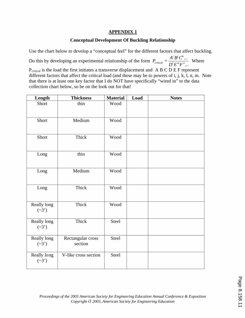
3. Active Learning in Mechanics of Materials Courses Several active learning techniques have been used in the Mechanics of Materials course at UT Austin and USAFA. The active learning methods were used to reinforce the concepts of bending stress, stress transformations, buckling and others. Several specific activities are reviewed below followed by assessment data describing the students’ perceptions. 3.1. Active Learning for Buckling Analysis In an attempt to give students a conceptual feel for the factors that affect buckling, students were provided with a number of different rods and asked to investigate their tendency to buckle. Specifically, groups consisting of three or four students were given ten different rods to experiment with. The rods differ in material type, length, cross sectional area and moment of inertia “I”. Appendix 1 shows the chart that students were given to guide their investigation. As the students fill in the chart, they gain a hands-on feel for how different features in a rod affect the rod’s tendency to buckle. Note that it is not expected that the students would be able to
develop the actual expression for the critical buckling load 2
2
)(KL
IEPcritical
π= . But it is expected
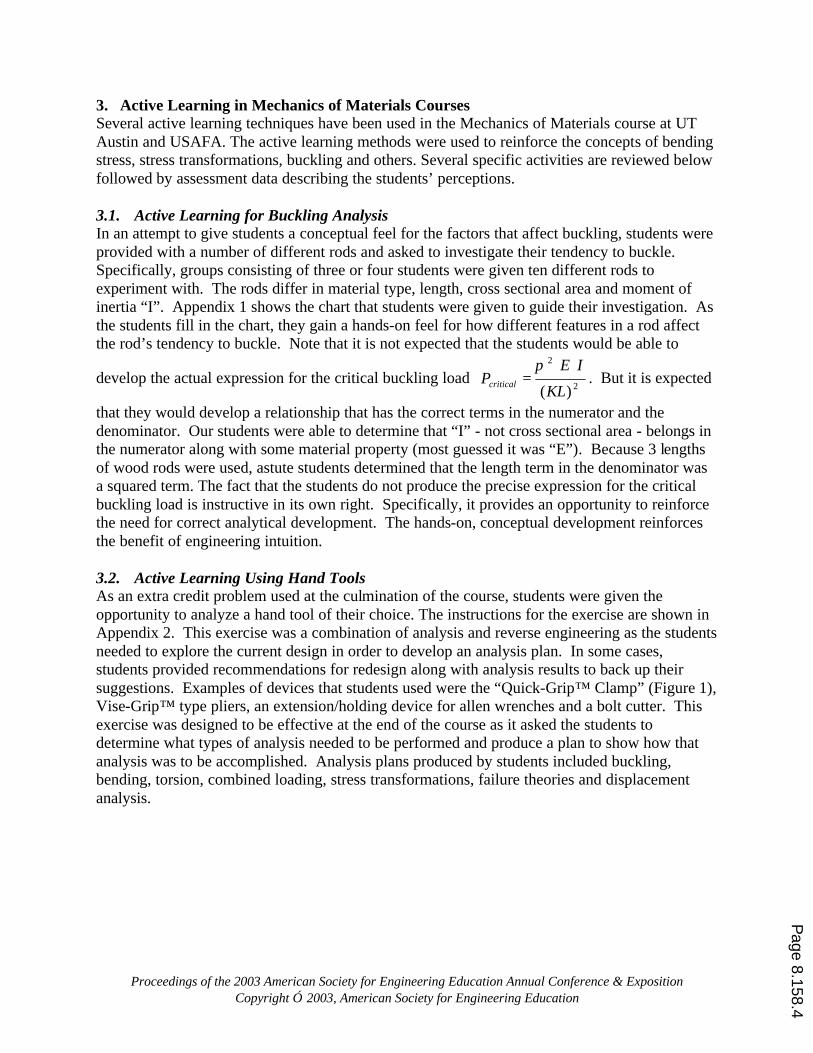
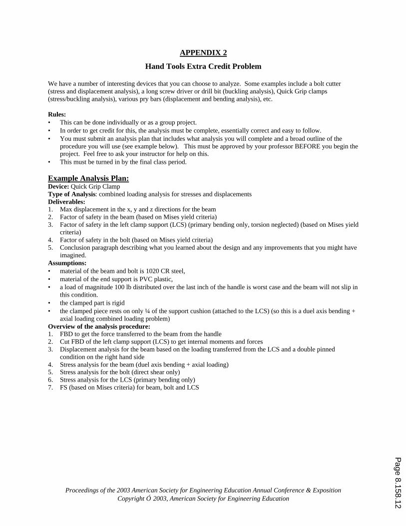
that they would develop a relationship that has the correct terms in the numerator and the denominator. Our students were able to determine that “I” - not cross sectional area - belongs in the numerator along with some material property (most guessed it was “E”). Because 3 lengths of wood rods were used, astute students determined that the length term in the denominator was a squared term. The fact that the students do not produce the precise expression for the critical buckling load is instructive in its own right. Specifically, it provides an opportunity to reinforce the need for correct analytical development. The hands-on, conceptual development reinforces the benefit of engineering intuition. 3.2. Active Learning Using Hand Tools As an extra credit problem used at the culmination of the course, students were given the opportunity to analyze a hand tool of their choice. The instructions for the exercise are shown in Appendix 2. This exercise was a combination of analysis and reverse engineering as the students needed to explore the current design in order to develop an analysis plan. In some cases, students provided recommendations for redesign along with analysis results to back up their suggestions. Examples of devices that students used were the “Quick-Grip™ Clamp” (Figure 1), Vise-Grip™ type pliers, an extension/holding device for allen wrenches and a bolt cutter. This exercise was designed to be effective at the end of the course as it asked the students to determine what types of analysis needed to be performed and produce a plan to show how that analysis was to be accomplished. Analysis plans produced by students included buckling, bending, torsion, combined loading, stress transformations, failure theories and displacement analysis.
Page 8.158.4
Proceedings of the 2003 American Society for Engineering Education Annual Conference & Exposition Copyright 2003, American Society for Engineering Education
Left Clamp Support
Beam
Handle
Support Cushion
Bolt
Figure 1: Quick-Grip™ clamp.
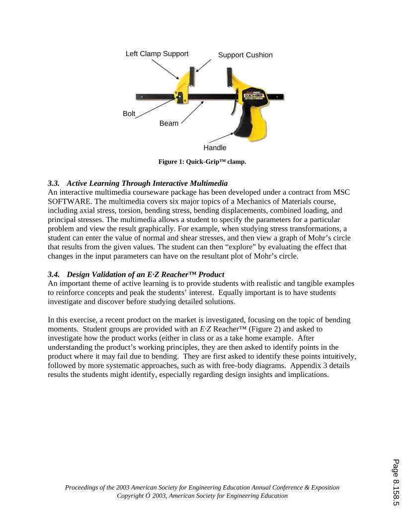
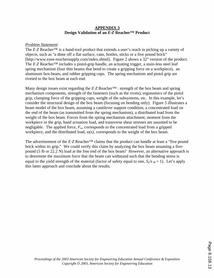
3.3. Active Learning Through Interactive Multimedia An interactive multimedia courseware package has been developed under a contract from MSC SOFTWARE. The multimedia covers six major topics of a Mechanics of Materials course, including axial stress, torsion, bending stress, bending displacements, combined loading, and principal stresses. The multimedia allows a student to specify the parameters for a particular problem and view the result graphically. For example, when studying stress transformations, a student can enter the value of normal and shear stresses, and then view a graph of Mohr’s circle that results from the given values. The student can then “explore” by evaluating the effect that changes in the input parameters can have on the resultant plot of Mohr’s circle. 3.4. Design Validation of an E·Z Reacher™ Product An important theme of active learning is to provide students with realistic and tangible examples to reinforce concepts and peak the students’ interest. Equally important is to have students investigate and discover before studying detailed solutions. In this exercise, a recent product on the market is investigated, focusing on the topic of bending moments. Student groups are provided with an E·Z Reacher™ (Figure 2) and asked to investigate how the product works (either in class or as a take home example. After understanding the product’s working principles, they are then asked to identify points in the product where it may fail due to bending. They are first asked to identify these points intuitively, followed by more systematic approaches, such as with free-body diagrams. Appendix 3 details results the students might identify, especially regarding design insights and implications.
Page 8.158.5
Proceedings of the 2003 American Society for Engineering Education Annual Conference & Exposition Copyright 2003, American Society for Engineering Education
Pistol-GripHandle
Trigger
Rivet Fasteners
Box Beam
Spring Mechanism
Rubber GrippingCups
32 in
A
A
Section A-A:
Figure 2: E·Z Reacher™ extended reach pick-up tool.
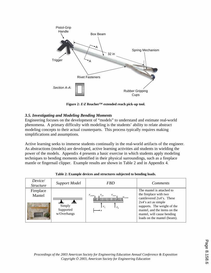
3.5. Investigating and Modeling Bending Moments Engineering focuses on the development of “models” to understand and estimate real-world phenomena. A primary difficulty with modeling is the students’ ability to relate abstract modeling concepts to their actual counterparts. This process typically requires making simplifications and assumptions. Active learning seeks to immerse students continually in the real-world artifacts of the engineer. As abstractions (models) are developed, active learning activities aid students in wielding the power of the models. Appendix 4 presents a basic exercise in which students apply modeling techniques to bending moments identified in their physical surroundings, such as a fireplace mantle or fingernail clipper. Example results are shown in Table 2 and in Appendix 4.
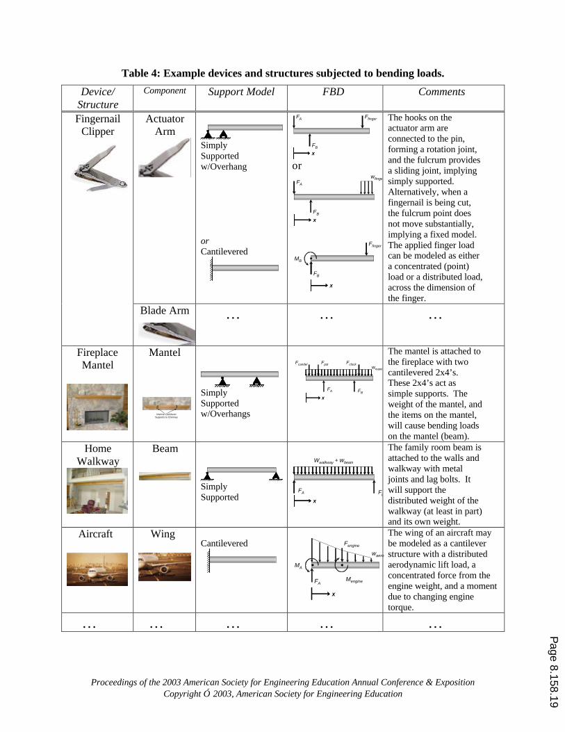
Table 2: Example devices and structures subjected to bending loads.
Device/ Structure Support Model FBD Comments
Fireplace Mantel
Simply
Supported w/Overhangs
wmantel
FA FB
xx
Fcandel Fpot Fclock
The mantel is attached to the fireplace with two cantilevered 2x4’s. These 2x4’s act as simple supports. The weight of the mantel, and the items on the mantel, will cause bending loads on the mantel (beam).
Page 8.158.6
Proceedings of the 2003 American Society for Engineering Education Annual Conference & Exposition Copyright 2003, American Society for Engineering Education
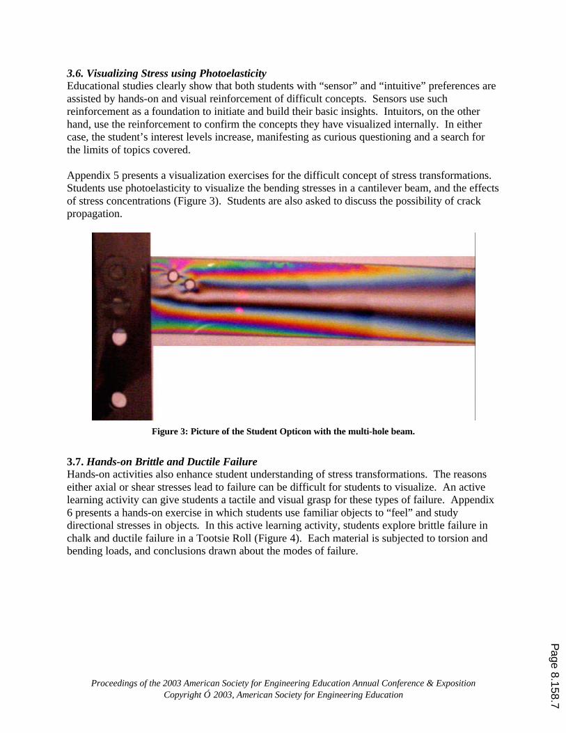
3.6. Visualizing Stress using Photoelasticity Educational studies clearly show that both students with “sensor” and “intuitive” preferences are assisted by hands-on and visual reinforcement of difficult concepts. Sensors use such reinforcement as a foundation to initiate and build their basic insights. Intuitors, on the other hand, use the reinforcement to confirm the concepts they have visualized internally. In either case, the student’s interest levels increase, manifesting as curious questioning and a search for the limits of topics covered. Appendix 5 presents a visualization exercises for the difficult concept of stress transformations. Students use photoelasticity to visualize the bending stresses in a cantilever beam, and the effects of stress concentrations (Figure 3). Students are also asked to discuss the possibility of crack propagation.
Figure 3: Picture of the Student Opticon with the multi-hole beam.
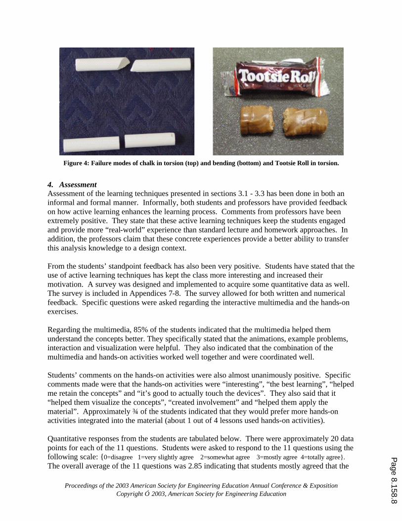
3.7. Hands-on Brittle and Ductile Failure Hands-on activities also enhance student understanding of stress transformations. The reasons either axial or shear stresses lead to failure can be difficult for students to visualize. An active learning activity can give students a tactile and visual grasp for these types of failure. Appendix 6 presents a hands-on exercise in which students use familiar objects to “feel” and study directional stresses in objects. In this active learning activity, students explore brittle failure in chalk and ductile failure in a Tootsie Roll (Figure 4). Each material is subjected to torsion and bending loads, and conclusions drawn about the modes of failure.
Page 8.158.7
Proceedings of the 2003 American Society for Engineering Education Annual Conference & Exposition Copyright 2003, American Society for Engineering Education
Figure 4: Failure modes of chalk in torsion (top) and bending (bottom) and Tootsie Roll in torsion.
4. Assessment Assessment of the learning techniques presented in sections 3.1 - 3.3 has been done in both an informal and formal manner. Informally, both students and professors have provided feedback on how active learning enhances the learning process. Comments from professors have been extremely positive. They state that these active learning techniques keep the students engaged and provide more “real-world” experience than standard lecture and homework approaches. In addition, the professors claim that these concrete experiences provide a better ability to transfer this analysis knowledge to a design context. From the students’ standpoint feedback has also been very positive. Students have stated that the use of active learning techniques has kept the class more interesting and increased their motivation. A survey was designed and implemented to acquire some quantitative data as well. The survey is included in Appendices 7-8. The survey allowed for both written and numerical feedback. Specific questions were asked regarding the interactive multimedia and the hands-on exercises. Regarding the multimedia, 85% of the students indicated that the multimedia helped them understand the concepts better. They specifically stated that the animations, example problems, interaction and visualization were helpful. They also indicated that the combination of the multimedia and hands-on activities worked well together and were coordinated well. Students’ comments on the hands-on activities were also almost unanimously positive. Specific comments made were that the hands-on activities were “interesting”, “the best learning”, “helped me retain the concepts” and “it’s good to actually touch the devices”. They also said that it “helped them visualize the concepts”, “created involvement” and “helped them apply the material”. Approximately ¾ of the students indicated that they would prefer more hands-on activities integrated into the material (about 1 out of 4 lessons used hands-on activities). Quantitative responses from the students are tabulated below. There were approximately 20 data points for each of the 11 questions. Students were asked to respond to the 11 questions using the following scale: {0=disagree 1=very slightly agree 2=somewhat agree 3=mostly agree 4=totally agree}. The overall average of the 11 questions was 2.85 indicating that students mostly agreed that the
Page 8.158.8
Proceedings of the 2003 American Society for Engineering Education Annual Conference & Exposition Copyright 2003, American Society for Engineering Education
active learning techniques were helpful. Noting that the first few questions cover the multimedia and the later questions cover the hands-on activities, it can be seen that in a general sense, the students were more positive about the hands-on then they were about the multimedia. It is possible that this is influenced by the fact that using the multimedia was not a required part of the course. Many students (50%) did not even take the initiative to use the software outside of class. However, those that did indicated a substantial benefit. Finally, it is noteworthy that the highest score came from the question regarding the hands-on making the content more interesting. Although “making the content more interesting” is not the objective of the educational enhancements directly, increasing interest level is likely to increase learning as well.
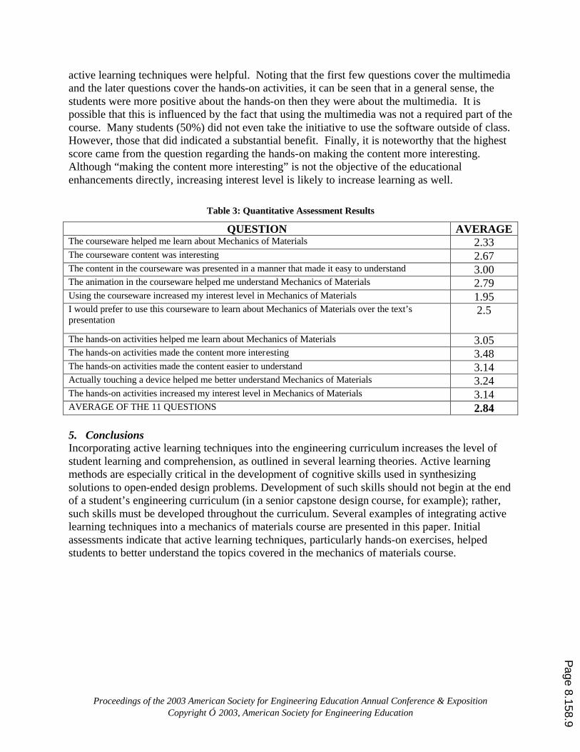
Table 3: Quantitative Assessment Results
QUESTION AVERAGE The courseware helped me learn about Mechanics of Materials 2.33 The courseware content was interesting 2.67 The content in the courseware was presented in a manner that made it easy to understand 3.00 The animation in the courseware helped me understand Mechanics of Materials 2.79 Using the courseware increased my interest level in Mechanics of Materials 1.95 I would prefer to use this courseware to learn about Mechanics of Materials over the text’s presentation
2.5
The hands-on activities helped me learn about Mechanics of Materials 3.05 The hands-on activities made the content more interesting 3.48 The hands-on activities made the content easier to understand 3.14 Actually touching a device helped me better understand Mechanics of Materials 3.24 The hands-on activities increased my interest level in Mechanics of Materials 3.14 AVERAGE OF THE 11 QUESTIONS 2.84 5. Conclusions Incorporating active learning techniques into the engineering curriculum increases the level of student learning and comprehension, as outlined in several learning theories. Active learning methods are especially critical in the development of cognitive skills used in synthesizing solutions to open-ended design problems. Development of such skills should not begin at the end of a student’s engineering curriculum (in a senior capstone design course, for example); rather, such skills must be developed throughout the curriculum. Several examples of integrating active learning techniques into a mechanics of materials course are presented in this paper. Initial assessments indicate that active learning techniques, particularly hands-on exercises, helped students to better understand the topics covered in the mechanics of materials course.
Page 8.158.9
Proceedings of the 2003 American Society for Engineering Education Annual Conference & Exposition Copyright 2003, American Society for Engineering Education
References
1. Bonwell, C., and J. Eison, “Active Learning: Creating Excitement in the Classroom,” ASHE-ERIC Higher Education Report No. 1, 1991 (http://www.ntlf.com/html/lib/bib/91-9dig.htm).
2. Bridge, J., “Incorporating Active Learning in an Engineering Materials Science Course,” Proceedings, ASEE Annual Conference and Exposition, 2001.
3. Nickels, K., “Do’s and Don’ts of Introducing Active Learning Techniques,” Proceedings, ASEE Annual Conference.
4. Kolb, D. A., Experiential Learning: Experience as the Source of Learning and Development. Prentice Hall, Englewood Cliffs, NJ, 1984.
5. Krathwohl, D. R., Bloom, B. S., and Maisa, B. B., “Taxonomy of Educational Objectives: The Classification of Educational Goals,” Handbook II, Affective Domain, New York: David McKay Co. Inc, 1964.
6. Agogino, A., and Shi, S., “Scaffolding Knowledge Integration through Designing Multimedia Case Studies of Engineering Design,” Proceedings of the ASEE Frontiers in Education conference, pp. D1.1-1.4, 1995.
7. Linn, M. C., “Designing Computer Environments for Engineering and Computer Science: Scaffolded Knowledge Integration Framework,” Journal of Science Education and Technology, Vol. 4, No. 2, 1995.
Biographical Information ALAN DUTSON is an faculty member in the Mechanical Engineering Department at Brigham Young University - Idaho. He joined the department in 2002 after completing his Ph.D. in the Mechanical Engineering from the University of Texas at Austin. His research interests include mechanical design and product development, with an emphasis on rapid prototyping. Alan has also conducted research on undergraduate capstone education. MATTHEW G. GREEN is a Ph.D. student at The University of Texas, Department of Mechanical Engineering. The objective of his research is to investigate the use of engineering design to improve the quality of life in developing countries. Topics include the design of affordable transportation, training engineers to design for marginalized populations, assistive devices for persons with disabilities, and remote power generation. KRISTIN WOOD is the Cullen Trust Endowed Professor in Engineering at The University of Texas, Department of Mechanical Engineering. Dr. Wood’s current research interests focus on product design, development, and evolution. The current and near-future objective of this research is to develop design strategies, representations, and languages that will result in more comprehensive design tools, innovative manufacturing techniques, and design teaching aids at the college, pre-college, and industrial levels. Contact: [email protected].
DAN JENSEN is a professor of Engineering Mechanics at the U.S. Air Force Academy. He received his B.S., M.S. and Ph.D. from the University of Colorado at Boulder. He has worked for Texas Instruments, Lockheed Martin, NASA, University of the Pacific, Lawrence Berkeley National Lab and MacNeal-Schwendler Corp. His research includes development of innovative design methodologies and enhancement of engineering education.
Page 8.158.10
Proceedings of the 2003 American Society for Engineering Education Annual Conference & Exposition Copyright 2003, American Society for Engineering Education
APPENDIX 1
Conceptual Development Of Buckling Relationship Use the chart below to develop a “conceptual feel” for the different factors that affect buckling.
Do this by developing an experimental relationship of the form ......
i j k
critical l m n
A B CP
D E F= Where
Pcritical is the load the first initiates a transverse displacement and A B C D E F represent different factors that affect the critical load (and these may be to powers of i, j, k, l, n, m. Note that there is at least one key factor that I do NOT have specifically “wired in” to the data collection chart below, so be on the look out for that!
Length Thickness Material Load Notes Short thin Wood
Short Medium Wood
Short Thick Wood
Long thin Wood
Long Medium Wood
Long Thick Wood
Really long (~3’)
Thick Wood
Really long (~3’)
Thick Steel
Really long (~3’)
Rectangular cross section
Steel
Really long (~3’)
V-like cross section Steel
Page 8.158.11
Proceedings of the 2003 American Society for Engineering Education Annual Conference & Exposition Copyright 2003, American Society for Engineering Education
APPENDIX 2
Hand Tools Extra Credit Problem We have a number of interesting devices that you can choose to analyze. Some examples include a bolt cutter (stress and displacement analysis), a long screw driver or drill bit (buckling analysis), Quick Grip clamps (stress/buckling analysis), various pry bars (displacement and bending analysis), etc. Rules: • This can be done individually or as a group project. • In order to get credit for this, the analysis must be complete, essentially correct and easy to follow. • You must submit an analysis plan that includes what analysis you will complete and a broad outline of the
procedure you will use (see example below). This must be approved by your professor BEFORE you begin the project. Feel free to ask your instructor for help on this.
• This must be turned in by the final class period. Example Analysis Plan: Device: Quick Grip Clamp Type of Analysis: combined loading analysis for stresses and displacements Deliverables: 1. Max displacement in the x, y and z directions for the beam 2. Factor of safety in the beam (based on Mises yield criteria) 3. Factor of safety in the left clamp support (LCS) (primary bending only, torsion neglected) (based on Mises yield
criteria) 4. Factor of safety in the bolt (based on Mises yield criteria) 5. Conclusion paragraph describing what you learned about the design and any improvements that you might have
imagined. Assumptions: • material of the beam and bolt is 1020 CR steel, • material of the end support is PVC plastic, • a load of magnitude 100 lb distributed over the last inch of the handle is worst case and the beam will not slip in
this condition. • the clamped part is rigid • the clamped piece rests on only ¼ of the support cushion (attached to the LCS) (so this is a duel axis bending +
axial loading combined loading problem) Overview of the analysis procedure: 1. FBD to get the force transferred to the beam from the handle 2. Cut FBD of the left clamp support (LCS) to get internal moments and forces 3. Displacement analysis for the beam based on the loading transferred from the LCS and a double pinned
condition on the right hand side 4. Stress analysis for the beam (duel axis bending + axial loading) 5. Stress analysis for the bolt (direct shear only) 6. Stress analysis for the LCS (primary bending only) 7. FS (based on Mises criteria) for beam, bolt and LCS
Page 8.158.12
Proceedings of the 2003 American Society for Engineering Education Annual Conference & Exposition Copyright 2003, American Society for Engineering Education
APPENDIX 3 Design Validation of an E·Z Reacher™ Product
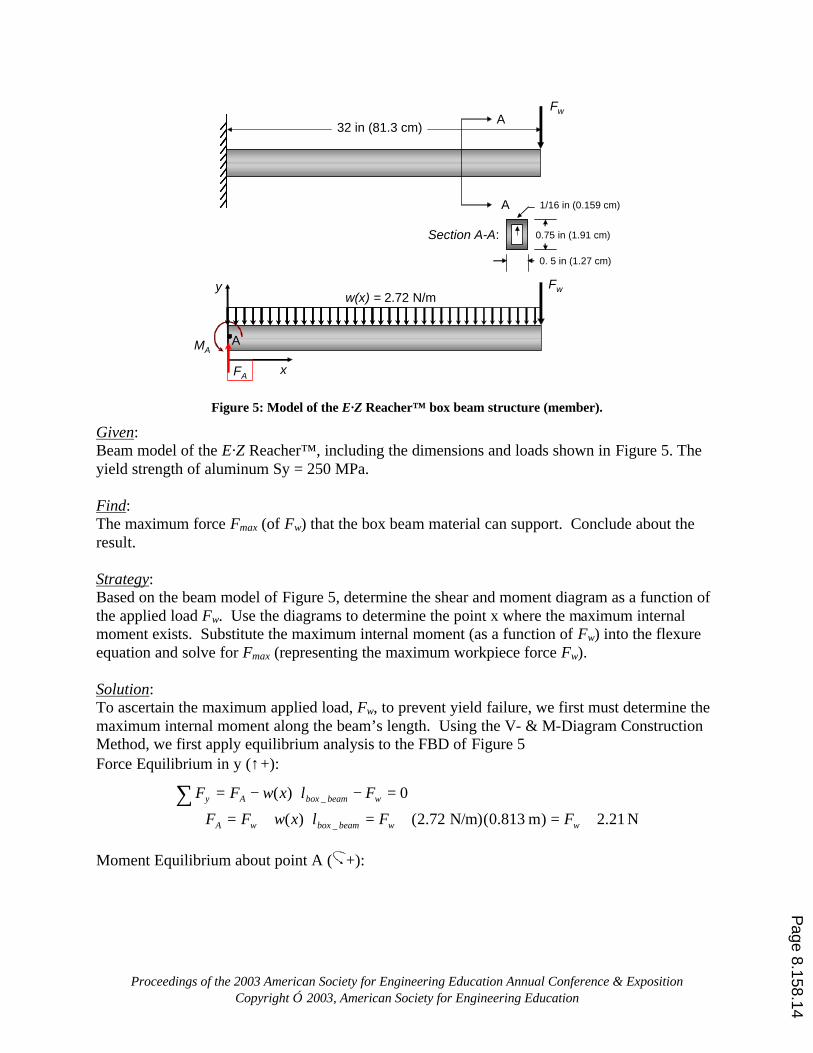
Problem Statement: The E·Z Reacher™ is a hand-tool product that extends a user’s reach in picking up a variety of objects, such as “a dime off a flat surface, cans, bottles, sticks or a five pound brick” [http://www.ezee-reachersupply.com/index.shtml]. Figure 2 shows a 32” version of the product. The E·Z Reacher™ includes a pistol-grip handle, an actuating trigger, a stain-less steel leaf spring mechanism (four thin beams that bend to create a gripping force on a workpiece), an aluminum box-beam, and rubber gripping cups. The spring mechanism and pistol grip are riveted to the box beam at each end. Many design issues exist regarding the E·Z Reacher™ : strength of the box beam and spring mechanism components, strength of the fasteners (such as the rivets), ergonomics of the pistol grip, clamping force of the gripping cups, weight of the subsystems, etc. In this example, let’s consider the structural design of the box beam (focusing on bending only). Figure 5 illustrates a beam model of the box beam, assuming a cantilever support condition, a concentrated load on the end of the beam (as transmitted from the spring mechanism), a distributed load from the weight of the box beam. Forces from the spring mechanism attachment, moment from the workpiece in the grip, hand actuation load, and transverse shear stresses are assumed to be negligable. The applied force, Fw, corresponds to the concentrated load from a gripped workpiece, and the distributed load, w(x), corresponds to the weight of the box beam. The advertisement of the E·Z Reacher™ claims that the product can handle at least a “five pound brick within its grip.” We could verify this claim by analyzing the box beam assuming a five-pound (5 lb or 22.2 N) load at the free end of the box beam? However, an alternative approach is to determine the maximum force that the beam can withstand such that the bending stress is equal to the yield strength of the material (factor of safety equal to one, Sy/σM = 1). Let’s apply this latter approach and conclude about the results.
Page 8.158.13
Proceedings of the 2003 American Society for Engineering Education Annual Conference & Exposition Copyright 2003, American Society for Engineering Education
Fw
32 in (81.3 cm)A
A
Section A-A:
x
y
FA
MAA
Fww(x) = 2.72 N/m
0.75 in (1.91 cm)
0. 5 in (1.27 cm)
1/16 in (0.159 cm)
Figure 5: Model of the E·Z Reacher™ box beam structure (member).
Given: Beam model of the E·Z Reacher™, including the dimensions and loads shown in Figure 5. The yield strength of aluminum Sy = 250 MPa. Find: The maximum force Fmax (of Fw) that the box beam material can support. Conclude about the result. Strategy: Based on the beam model of Figure 5, determine the shear and moment diagram as a function of the applied load Fw. Use the diagrams to determine the point x where the maximum internal moment exists. Substitute the maximum internal moment (as a function of Fw) into the flexure equation and solve for Fmax (representing the maximum workpiece force Fw). Solution: To ascertain the maximum applied load, Fw, to prevent yield failure, we first must determine the maximum internal moment along the beam’s length. Using the V- & M-Diagram Construction Method, we first apply equilibrium analysis to the FBD of Figure 5 Force Equilibrium in y (↑+):
N 21.2)m0.813(N/m)72.2()(
0)(
_
_
+=+=⋅+=⇒
=−⋅−=∑wwbeamboxwA
wbeamboxAy
FFlxwFF
FlxwFF
Moment Equilibrium about point A ( +):
Page 8.158.14
Proceedings of the 2003 American Society for Engineering Education Annual Conference & Exposition Copyright 2003, American Society for Engineering Education
__ _
2
_
( ) 02
(0.813 m)(2.72 N/m) 0.813 0.899 N m
2
box beamA w box beam box beam A
A w box beam w
lM F l w x l M
M F l F
= − ⋅ − ⋅ ⋅ + =
⇒ = ⋅ + = + ⋅
∑,
Based on these resolved reaction loads, we may section the box beam just before the applied work piece load at the free end, as shown in Figure 6. Applying force equilibrium to this section, Force Equilibrium in y (↑+):
( )[ ] N)72.2( 21.2)()(
0)(
xFxxwFxV
VxxwFF
wA
Ay
−+=⋅−=⇒
=−⋅−=∑
Using this result for V(x) and integrating Eqn. 5.4, we have
( )
2
( ) ( )
( ) ( ) 2.21 (2.72) 0.813 0.899 N m2A w w
M x V x dx
xM x V x dx M F x F
∆ = ⇒
= − = + − − − ⋅
∫
∫
x
y
FA
MAA
w(x) = 2.72 N/m
M
V
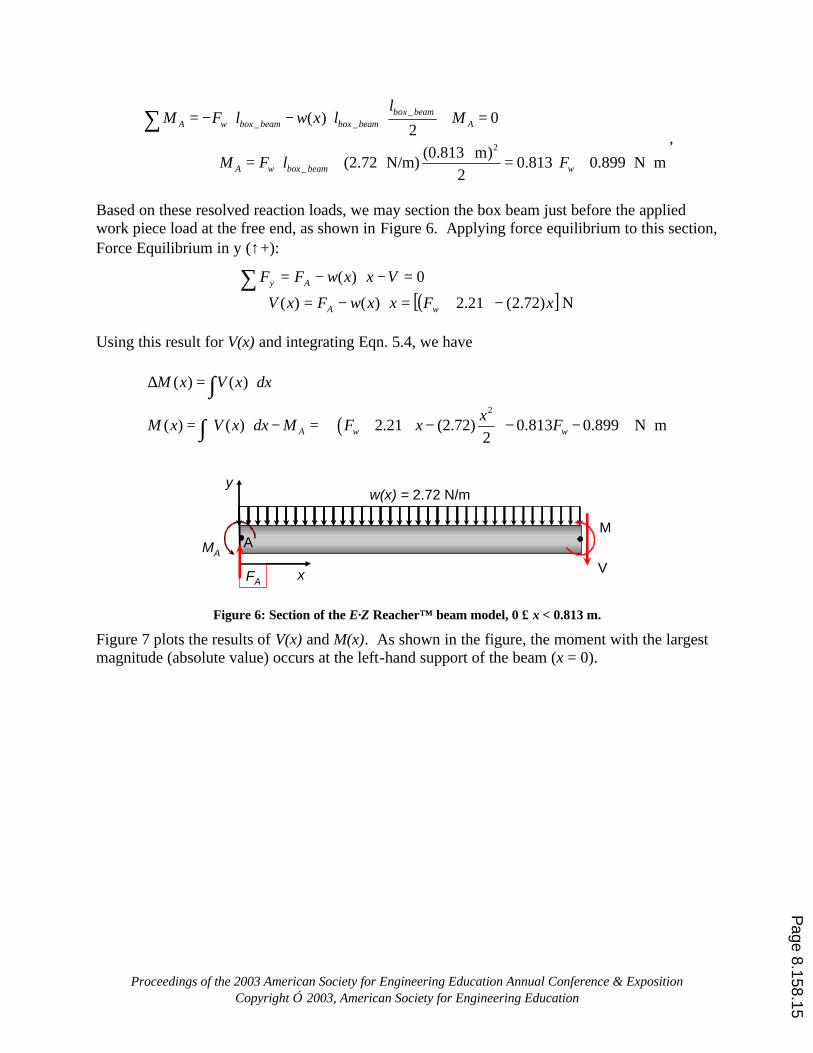
Figure 6: Section of the E·Z Reacher™ beam model, 0 ≤ x < 0.813 m.
Figure 7 plots the results of V(x) and M(x). As shown in the figure, the moment with the largest magnitude (absolute value) occurs at the left-hand support of the beam (x = 0).
Page 8.158.15
Proceedings of the 2003 American Society for Engineering Education Annual Conference & Exposition Copyright 2003, American Society for Engineering Education
x
y
FA
MAA
Fww(x) = 2.72 N/m
x
V(x)
FAFw
x
M(x)
-MA
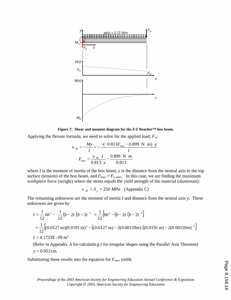
Figure 7: Shear and moment diagram for the E·Z Reacher™ box beam.
Applying the flexure formula, we need to solve for the applied load, Fw:
max
max
( 0.813 0.899 N m)
0.899 N m0.813 0.813
M
M
F yMyI I
IF
y
σ
σ
− − − ⋅ ⋅= − = −
⋅ ⋅⇒ = −
⋅
where I is the moment of inertia of the box beam, y is the distance from the neutral axis to the top surface (tension) of the box beam, and Fmax = Fw,max. In this case, we are finding the maximum workpiece force (weight) where the stress equals the yield strength of the material (aluminum):
C)(Appendix 250 MPaS yM ==σ
The remaining unknowns are the moment of inertia I and distance from the neutral axis y. These unknowns are given by
( )( ) ( )( )[ ]
( )( )[ ]
cm953.0Theorem) Axis Parallel theusing shapesirregular for gcalculatinfor AAppendix (Refer to
m09-4.1733E
)00159.0(2)m0191.0()00159.0(2)m0127.0()m0191.0)(m0127.0(121
22121
22121
121
4
33
3333
=
=
−−−=
−−−=
−−−=
yI
I
mm
thtbbhthtbbhI
Substituting these results into the equation for Fmax yields Page 8.158.16
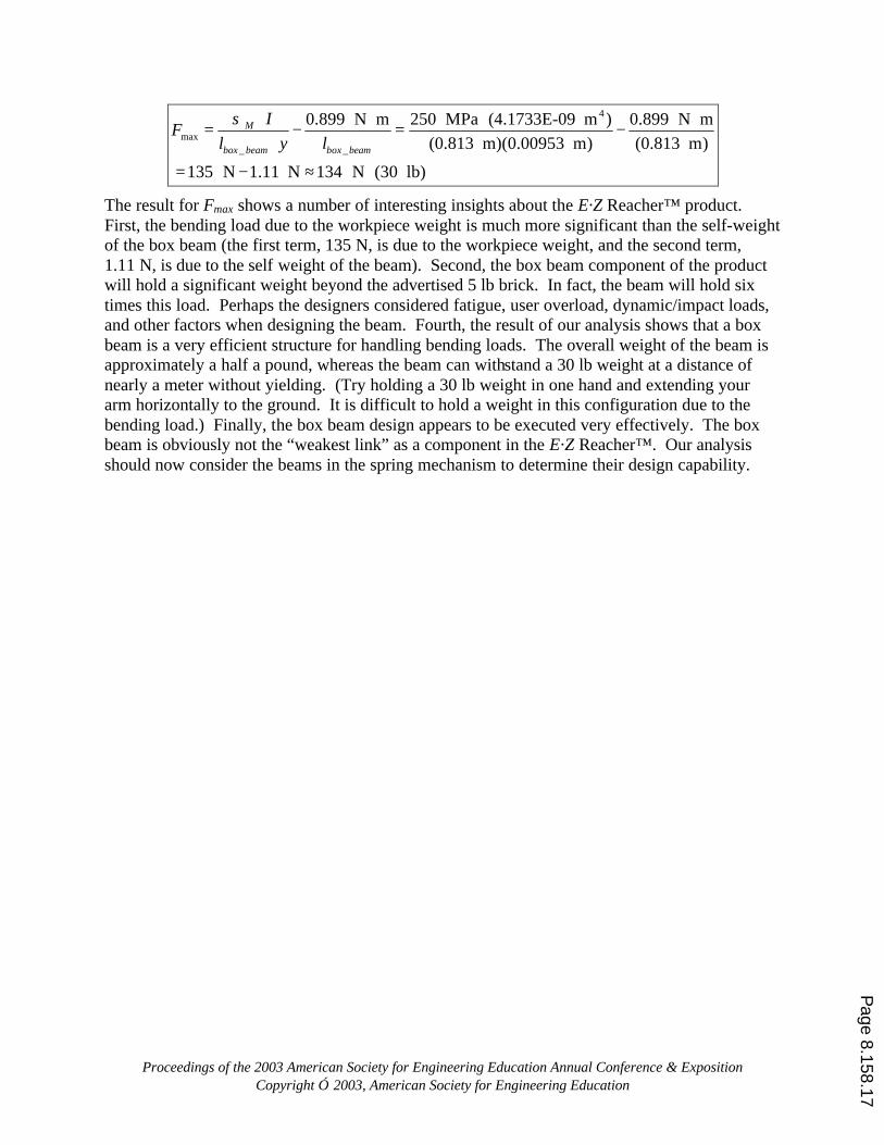
Proceedings of the 2003 American Society for Engineering Education Annual Conference & Exposition Copyright 2003, American Society for Engineering Education
4
max_ _
0.899 N m 250 MPa (4.1733E-09 m ) 0.899 N m(0.813 m)(0.00953 m) (0.813 m)
135 N 1.11 N 134 N (30 lb)
M
box beam box beam
IF
l y lσ ⋅ ⋅ ⋅
= − = −⋅
= − ≈
The result for Fmax shows a number of interesting insights about the E·Z Reacher™ product. First, the bending load due to the workpiece weight is much more significant than the self-weight of the box beam (the first term, 135 N, is due to the workpiece weight, and the second term, 1.11 N, is due to the self weight of the beam). Second, the box beam component of the product will hold a significant weight beyond the advertised 5 lb brick. In fact, the beam will hold six times this load. Perhaps the designers considered fatigue, user overload, dynamic/impact loads, and other factors when designing the beam. Fourth, the result of our analysis shows that a box beam is a very efficient structure for handling bending loads. The overall weight of the beam is approximately a half a pound, whereas the beam can withstand a 30 lb weight at a distance of nearly a meter without yielding. (Try holding a 30 lb weight in one hand and extending your arm horizontally to the ground. It is difficult to hold a weight in this configuration due to the bending load.) Finally, the box beam design appears to be executed very effectively. The box beam is obviously not the “weakest link” as a component in the E·Z Reacher™. Our analysis should now consider the beams in the spring mechanism to determine their design capability.
Page 8.158.17
Proceedings of the 2003 American Society for Engineering Education Annual Conference & Exposition Copyright 2003, American Society for Engineering Education
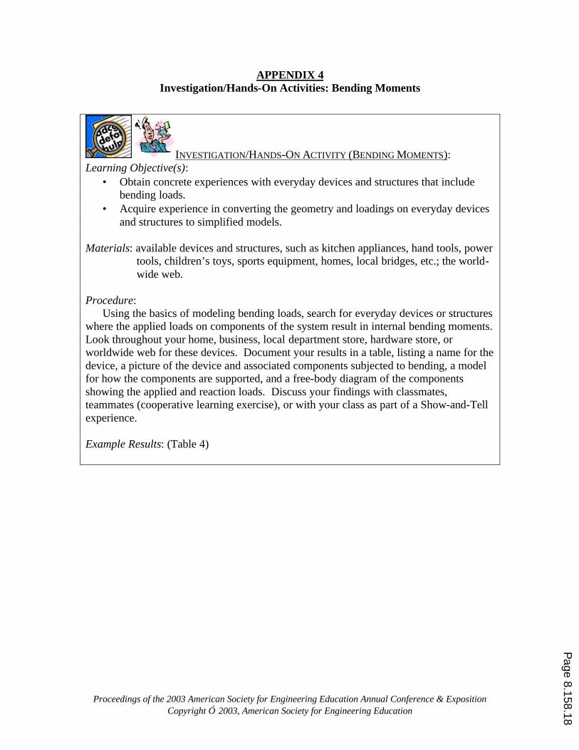
APPENDIX 4 Investigation/Hands-On Activities: Bending Moments
INVESTIGATION/HANDS-ON ACTIVITY (BENDING MOMENTS): Learning Objective(s): • Obtain concrete experiences with everyday devices and structures that include
bending loads. • Acquire experience in converting the geometry and loadings on everyday devices
and structures to simplified models. Materials: available devices and structures, such as kitchen appliances, hand tools, power
tools, children’s toys, sports equipment, homes, local bridges, etc.; the world-wide web.
Procedure: Using the basics of modeling bending loads, search for everyday devices or structures where the applied loads on components of the system result in internal bending moments. Look throughout your home, business, local department store, hardware store, or worldwide web for these devices. Document your results in a table, listing a name for the device, a picture of the device and associated components subjected to bending, a model for how the components are supported, and a free-body diagram of the components showing the applied and reaction loads. Discuss your findings with classmates, teammates (cooperative learning exercise), or with your class as part of a Show-and-Tell experience. Example Results: (Table 4)
Page 8.158.18
Proceedings of the 2003 American Society for Engineering Education Annual Conference & Exposition Copyright 2003, American Society for Engineering Education
Table 4: Example devices and structures subjected to bending loads.
Device/ Structure
Component Support Model FBD Comments
Actuator Arm
Simply Supported w/Overhang or Cantilevered
FfingerFA
FB
xx or
wfingerFA
FB
xx
Ffinger
FB
MB
xx
The hooks on the actuator arm are connected to the pin, forming a rotation joint, and the fulcrum provides a sliding joint, implying simply supported. Alternatively, when a fingernail is being cut, the fulcrum point does not move substantially, implying a fixed model. The applied finger load can be modeled as either a concentrated (point) load or a distributed load, across the dimension of the finger.
Fingernail Clipper
Blade Arm … … …
Fireplace Mantel
Mantel
Internal CantileverSupports to Chimney
Simply Supported w/Overhangs
wmantel
FA FB
xx
Fcandel Fpot Fclock
The mantel is attached to the fireplace with two cantilevered 2x4’s. These 2x4’s act as simple supports. The weight of the mantel, and the items on the mantel, will cause bending loads on the mantel (beam).
Home Walkway
Beam
Simply Supported
Wwalkway + wbeam
FA FB
xx
The family room beam is attached to the walls and walkway with metal joints and lag bolts. It will support the distributed weight of the walkway (at least in part) and its own weight.
Aircraft
Wing
Cantilevered
The wing of an aircraft may be modeled as a cantilever structure with a distributed aerodynamic lift load, a concentrated force from the engine weight, and a moment due to changing engine torque.
… … … … …
Fengine
FAMengine
xx
MA
waero
Page 8.158.19
Proceedings of the 2003 American Society for Engineering Education Annual Conference & Exposition Copyright 2003, American Society for Engineering Education
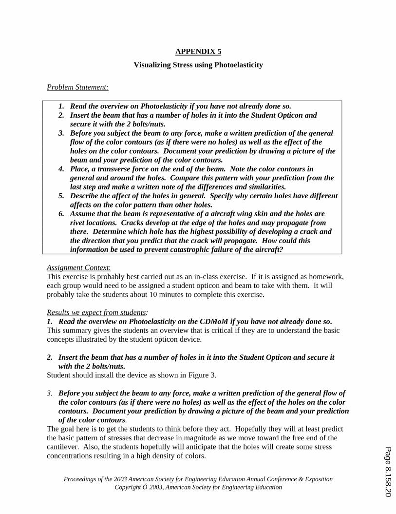
APPENDIX 5
Visualizing Stress using Photoelasticity
Problem Statement:
1. Read the overview on Photoelasticity if you have not already done so. 2. Insert the beam that has a number of holes in it into the Student Opticon and
secure it with the 2 bolts/nuts. 3. Before you subject the beam to any force, make a written prediction of the general
flow of the color contours (as if there were no holes) as well as the effect of the holes on the color contours. Document your prediction by drawing a picture of the beam and your prediction of the color contours.
4. Place, a transverse force on the end of the beam. Note the color contours in general and around the holes. Compare this pattern with your prediction from the last step and make a written note of the differences and similarities.
5. Describe the affect of the holes in general. Specify why certain holes have different affects on the color pattern than other holes.
6. Assume that the beam is representative of a aircraft wing skin and the holes are rivet locations. Cracks develop at the edge of the holes and may propagate from there. Determine which hole has the highest possibility of developing a crack and the direction that you predict that the crack will propagate. How could this information be used to prevent catastrophic failure of the aircraft?
Assignment Context: This exercise is probably best carried out as an in-class exercise. If it is assigned as homework, each group would need to be assigned a student opticon and beam to take with them. It will probably take the students about 10 minutes to complete this exercise. Results we expect from students: 1. Read the overview on Photoelasticity on the CDMoM if you have not already done so. This summary gives the students an overview that is critical if they are to understand the basic concepts illustrated by the student opticon device. 2. Insert the beam that has a number of holes in it into the Student Opticon and secure it
with the 2 bolts/nuts. Student should install the device as shown in Figure 3. 3. Before you subject the beam to any force, make a written prediction of the general flow of
the color contours (as if there were no holes) as well as the effect of the holes on the color contours. Document your prediction by drawing a picture of the beam and your prediction of the color contours.
The goal here is to get the students to think before they act. Hopefully they will at least predict the basic pattern of stresses that decrease in magnitude as we move toward the free end of the cantilever. Also, the students hopefully will anticipate that the holes will create some stress concentrations resulting in a high density of colors.
Page 8.158.20
Proceedings of the 2003 American Society for Engineering Education Annual Conference & Exposition Copyright 2003, American Society for Engineering Education
4. Place a transverse force on the end of the beam. Note the color contours in general and
around the holes. Compare this pattern with your prediction from the last step and make a written note of the differences and similarities.
Student should achieve results as shown in Figure 3. 5. Describe the affect of the holes in general. Specify why certain holes have different affects
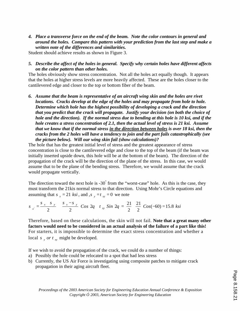
on the color pattern than other holes. The holes obviously show stress concentration. Not all the holes act equally though. It appears that the holes at higher stress levels are more heavily affected. These are the holes closer to the cantilevered edge and closer to the top or bottom fiber of the beam. 6. Assume that the beam is representative of an aircraft wing skin and the holes are rivet
locations. Cracks develop at the edge of the holes and may propagate from hole to hole. Determine which hole has the highest possibility of developing a crack and the direction that you predict that the crack will propagate. Justify your decision (on both the choice of hole and the direction). If the normal stress due to bending at this hole is 10 ksi, and if the hole creates a stress concentration of 2.1, then the actual level of stress is 21 ksi. Assume that we know that if the normal stress in the direction between holes is over 18 ksi, then the cracks from the 2 holes will have a tendency to join and the part fails catastrophically (see the picture below). Will our wing skin fail (show calculations)?
The hole that has the greatest initial level of stress and the greatest appearance of stress concentration is close to the cantilevered edge and close to the top of the beam (if the beam was initially inserted upside down, this hole will be at the bottom of the beam). The direction of the propagation of the crack will be the direction of the plane of the stress. In this case, we would assume that to be the plane of the bending stress. Therefore, we would assume that the crack would propagate vertically. The direction toward the next hole is -30° from the “worst-case” hole. As this is the case, they must transform the 21kis normal stress to that direction. Using Mohr’s Circle equations and assuming that 21x ksiσ = , and , 0y xyσ τ= = we note
/ 2 22 2
x y x yxyx
Cos Sinσ σ σ σ
σ θ τ θ+ −
= + + = 21 21
( 60) 15.82 2
Cos ksi+ − =
Therefore, based on these calculations, the skin will not fail. Note that a great many other factors would need to be considered in an actual analysis of the failure of a part like this! For starters, it is impossible to determine the exact stress concentration and whether a local y xyorσ τ might be developed. If we wish to avoid the propagation of the crack, we could do a number of things: a) Possibly the hole could be relocated to a spot that had less stress b) Currently, the US Air Force is investigating using composite patches to mitigate crack
propagation in their aging aircraft fleet. Page 8.158.21
Proceedings of the 2003 American Society for Engineering Education Annual Conference & Exposition Copyright 2003, American Society for Engineering Education
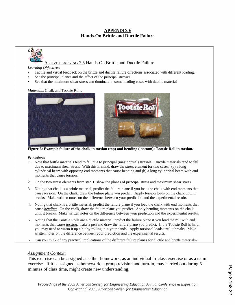
APPENDIX 6 Hands-On Brittle and Ductile Failure
ACTIVE LEARNING 7.5 Hands-On Brittle and Ductile Failure Learning Objectives: • Tactile and visual feedback on the brittle and ductile failure directions associated with different loading. • See the principal planes and the affect of the principal stresses • See that the maximum shear stress can dominate in some loading cases with ductile material Materials: Chalk and Tootsie Rolls
Figure 8: Example failure of the chalk in torsion (top) and bending ( bottom); Tootsie Roll in torsion. Procedure: 1. Note that brittle materials tend to fail due to principal (max normal) stresses. Ductile materials tend to fail
due to maximum shear stress. With this in mind, draw the stress element for two cases: (a) a long cylindrical beam with opposing end moments that cause bending and (b) a long cylindrical beam with end moments that cause torsion.
2. On the two stress elements from step 1, show the planes of principal stress and maximum shear stress.
3. Noting that chalk is a brittle material, predict the failure plane if you load the chalk with end moments that cause torsion. On the chalk, draw the failure plane you predict. Apply torsion loads on the chalk until it breaks. Make written notes on the difference between your prediction and the experimental results.
4. Noting that chalk is a brittle material, predict the failure plane if you load the chalk with end moments that cause bending. On the chalk, draw the failure plane you predict. Apply bending moments on the chalk until it breaks. Make written notes on the difference between your prediction and the experimental results.
5. Noting that the Tootsie Rolls are a ductile material, predict the failure plane if you load the roll with end moments that cause torsion. Take a pen and draw the failure plane you predict. If the Tootsie Roll is hard, you may need to warm it up a bit by rolling it in your hands. Apply torsional loads until it breaks. Make written notes on the difference between your prediction and the experimental results.
6. Can you think of any practical implications of the different failure planes for ductile and brittle materials?
Assignment Context: This exercise can be assigned as either homework, as an individual in-class exercise or as a team exercise. If it is assigned as homework, a group revision and turn-in, may carried out during 5 minutes of class time, might create new understanding.
Page 8.158.22
Proceedings of the 2003 American Society for Engineering Education Annual Conference & Exposition Copyright 2003, American Society for Engineering Education
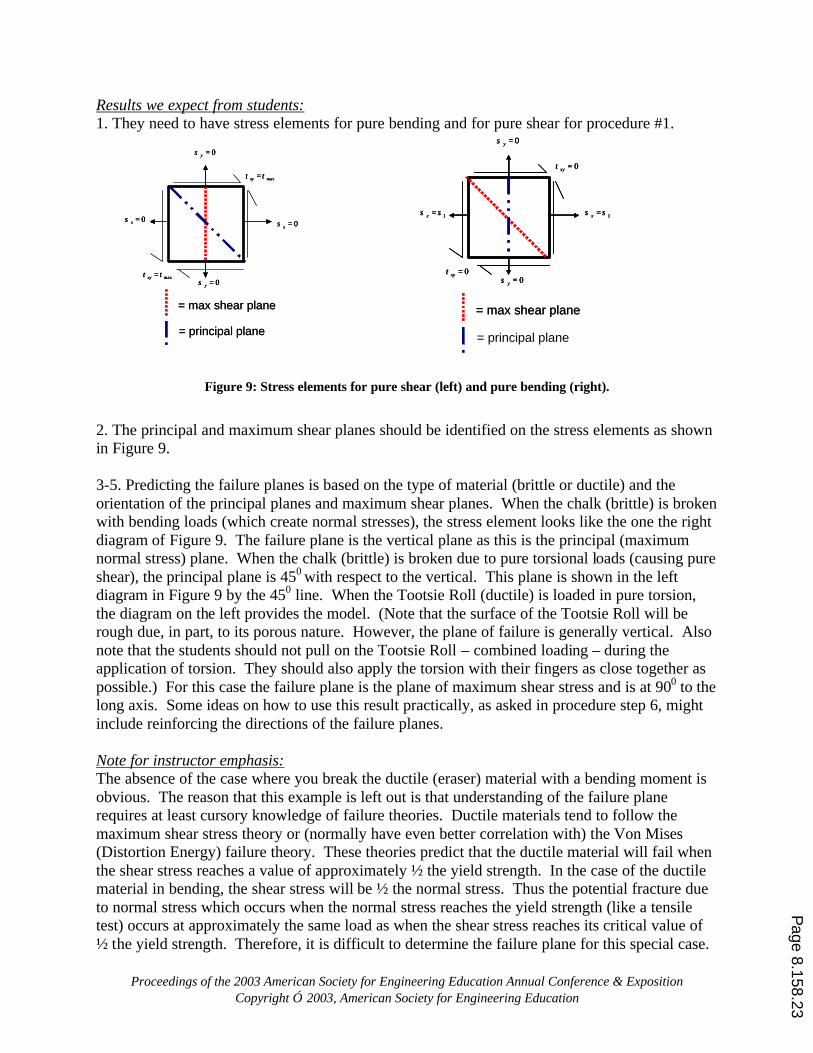
Results we expect from students: 1. They need to have stress elements for pure bending and for pure shear for procedure #1.
Figure 9: Stress elements for pure shear (left) and pure bending (right).
2. The principal and maximum shear planes should be identified on the stress elements as shown in Figure 9. 3-5. Predicting the failure planes is based on the type of material (brittle or ductile) and the orientation of the principal planes and maximum shear planes. When the chalk (brittle) is broken with bending loads (which create normal stresses), the stress element looks like the one the right diagram of Figure 9. The failure plane is the vertical plane as this is the principal (maximum normal stress) plane. When the chalk (brittle) is broken due to pure torsional loads (causing pure shear), the principal plane is 450 with respect to the vertical. This plane is shown in the left diagram in Figure 9 by the 450 line. When the Tootsie Roll (ductile) is loaded in pure torsion, the diagram on the left provides the model. (Note that the surface of the Tootsie Roll will be rough due, in part, to its porous nature. However, the plane of failure is generally vertical. Also note that the students should not pull on the Tootsie Roll – combined loading – during the application of torsion. They should also apply the torsion with their fingers as close together as possible.) For this case the failure plane is the plane of maximum shear stress and is at 900 to the long axis. Some ideas on how to use this result practically, as asked in procedure step 6, might include reinforcing the directions of the failure planes. Note for instructor emphasis: The absence of the case where you break the ductile (eraser) material with a bending moment is obvious. The reason that this example is left out is that understanding of the failure plane requires at least cursory knowledge of failure theories. Ductile materials tend to follow the maximum shear stress theory or (normally have even better correlation with) the Von Mises (Distortion Energy) failure theory. These theories predict that the ductile material will fail when the shear stress reaches a value of approximately ½ the yield strength. In the case of the ductile material in bending, the shear stress will be ½ the normal stress. Thus the potential fracture due to normal stress which occurs when the normal stress reaches the yield strength (like a tensile test) occurs at approximately the same load as when the shear stress reaches its critical value of ½ the yield strength. Therefore, it is difficult to determine the failure plane for this special case.
= principal plane
0xyτ =
0xyτ =
0yσ =
0yσ =
1xσ σ= 1xσ σ=
= max shear plane
0xyτ =
0xyτ =
0yσ =
0yσ =
1xσ σ= 1xσ σ=
0xyτ =
0xyτ =
0yσ =
0yσ =
1xσ σ= 1xσ σ=
= max shear plane
maxxyτ τ=
maxxyτ τ=
0yσ =
0yσ =
0xσ = 0xσ =
= max shear plane
= principal plane
maxxyτ τ=
maxxyτ τ=
0yσ =
0yσ =
0xσ = 0xσ =
maxxyτ τ=
maxxyτ τ=
0yσ =
0yσ =
0xσ = 0xσ =
= max shear plane
= principal plane
Page 8.158.23
Proceedings of the 2003 American Society for Engineering Education Annual Conference & Exposition Copyright 2003, American Society for Engineering Education
APPENDIX 7 Survey On Hands-On & Courseware– Fall 2002 (Em 330)
This survey is intended to help me evaluate the effectiveness of the Vis-MoM Courseware and the hands-on illustrations we have used. Thanks in advance for your help! QUICK RECAP: I) Vis-MoM is the name of the courseware that was available on the K drive. This was used in class to illustrate combined loading, indeterminate bending problems and Stress Transformations (especially Mohr’s circle). II) Hands-on illustrations used in class included the wood and metal rods for buckling, the F15 wing for composites, the chalk & balsa wood for stress transformations, the in-class “blow torch on strain gage demo, the 2 labs (pressure vessels and buckling) and the different tools available for the optional homework 1. When we used the courseware in class, did the visualizations help you to better understand the concepts? Please explain 2. Did you use the courseware outside of class? If you did not, why not? If I had given you a CD with the courseware, would you have used that?
3. What did you find most helpful about the courseware? What could be done to improve the courseware? 4. Compare the lectures that include hands-on activities to those that did not? 5. Specifically describe how the hands-on either enhanced your learning or distracted from it. 6. Would you recommend introducing more hands-on learning in the class? 7. In what ways do you think the combination of courseware and hands-on either work well together (to help you
learn) or do not work well together. P
age 8.158.24
Proceedings of the 2003 American Society for Engineering Education Annual Conference & Exposition Copyright 2003, American Society for Engineering Education
APPENDIX 8 Survey On Active Learning Content for Mechanics
Circle the number that best represents your answer to the following statements 0=disagree 1=very slightly agree 2=somewhat agree 3=mostly agree 4=totally agree a. The courseware helped me learn about Mechanics of Materials 0 1 2 3 4 b. The courseware content was interesting 0 1 2 3 4 c. The content in the courseware was presented in a manner that made it easy to understand 0 1 2 3 4 d. The animation in the courseware helped me understand Mechanics of Materials 0 1 2 3 4 e. Using the courseware increased my interest level in Mechanics of Materials 0 1 2 3 4 f. I would prefer to use this courseware to learn about Mechanics of Materials over the text’s presentation 0 1 2 3 4 g. The hands-on activities helped me learn about Mechanics of Materials 0 1 2 3 4 h. The hands-on activities made the content more interesting 0 1 2 3 4 i. The hands-on activities made the content easier to understand 0 1 2 3 4 j. Actually touching a device helped me better understand Mechanics of Materials 0 1 2 3 4 k. The hands-on activities increased my interest level in Mechanics of Materials 0 1 2 3 4
Page 8.158.25