Embed Size (px)
Citation preview

Active Fluid Borne Noise Reduction for Aviation Hydraulic Pumps
Dipl.-Ing. Arne Waitschat Institute of Aircraft Systems Engineering (FST), Hamburg University of Technology (TUHH), Neßpriel 5, D-21129 Hamburg, E-mail: [email protected]
Prof. Dr.-Ing. Frank Thielecke Institute of Aircraft Systems Engineering (FST), Hamburg University of Technology (TUHH), Neßpriel 5, D-21129 Hamburg, E-mail: [email protected]
Dipl.-Ing. Robert M. Behr Airbus Operations GmbH, Hydraulic Performance & Integrity, Airbus Allee 1, D-28199 Bremen, Email: [email protected]
Dipl.-Ing. Ulrich Heise Airbus Operations GmbH, Interior & Near Field Noise, Kreetslag 10, D-21129 Hamburg, [email protected]
Abstract The aviation environment holds challenging application constraints for efficient
hydraulic system noise reduction devices. Besides strong limits on component weight
and size, high safety and reliability standards demand simple solutions. Hence, basic
silencers like inline expansion chambers and Helmholtz-Resonators are state-of-the-art
aboard commercial aircrafts. Unfortunately, they do not meet today’s noise attenuation
aims regarding passenger comfort and equipment durability. Significant attenuation
performance is expected from active concepts that generate anti-phase noise.
However, such concepts remain a long term approach unless related costs, e.g. due to
additional power allocation and real-time control equipment can be avoided. In this
paper an active fluid borne noise attenuation concept is discussed that accounts for the
mentioned constraints. An aircraft hydraulic pump is considered as main noise source.
The active attenuator is an in-house rotary valve design. The basic feature is a known
direct shaft coupling principle of pump and rotary valve, so no speed/ frequency control
of the valve and no separate power supply are required. The common-shaft principle is
further simplified here and proposed as integral feature of future “smart pumps”.
KEYWORDS: Aircraft Hydraulic System, Hydraulic System Noise, Fluid Borne
Noise, Pump Flow Ripple, Pump Impedance, Active Attenuation,
Direct Drain Principle, Rotary Valve, Common Shaft Principle
Group F - Pumps | Paper F-4 307
1. Introduction The potential & feasibility to reduce flow/pressure ripple – fluid borne noise (FBN) – of
hydraulic pumps by a rotary valve in common shaft application was presented by
Goenechea, see e.g. /1/. Taking the common shaft principle as starting point, further
modifications are discussed in the concept-section, chapter 2, in order to satisfy the
aviation constraints. Related design parameters and a simulation model are presented
in chapter 3 and 4. The model is built using the time domain FBN analysis capabilities
of the software DSHplus v3.9. In chapter 5, a laboratory demonstrator for experimental
validation is shown. It uses the pump test circuit of a dedicated FBN test rig at TUHH.
Relevant issues are listed below. Due to paper space only 1 to 3 are further discussed:
1. The attenuation performance in terms of pump flow ripple (source flow ripple)
reduction in the pump discharge line for anechoic (reflection-free) conditions.
2. The attenuator impact on the pumps suction line, because todays passive
reference silencers at pump discharge port tend to induce suction flow ripple.
3. The attenuator impact on the pump power balance in terms of a decreased
stationary pressure/ flow or increased power consumption of the electric motor.
4. The attenuator impact on the apparent pump impedance (source impedance),
which is a critical characteristic for interaction with (reflected) system ripples.
2. Concept Active attenuators tend to be an attractive alternative to passive silencers regarding
piston pump FBN reduction, especially for the fundamental and first harmonic pumping
frequency. These carry most of the ripple power and passive solutions usually require
large capacitance or inductance for lower frequencies, increasing silencer size/ weight.
In /1/ & /2/ some active attenuator concepts were compared, e.g. a Direct Principle
draining dynamic flow to a lower pressure level, and an Active Resistance Principle,
storing/releasing dynamic flow in/out a capacitance. Their use in aviation hydraulic
systems was considered by Kohlberg et al. in /3/. One of the considered attenuator
concepts was built and tested using a piezo-driven membrane actuator and is
discussed in more detail in /4/. A high attenuation performance was achieved but came
with many efforts. A realization by a rotary valve with pump shaft coupling enables to
spare many efforts like a separate power supply and a speed/ frequency control.
A rotary valve (RV) can be designed compact and robust. However, a realistic aviation
application would also demand to spare/ minimize any other onboard hardware and
software for RV amplitude and phase control. Hence, a knowledge-based (pre-) design
308 10th International Fluid Power Conference | Dresden 2016
of the pump-attenuator-assembly is required that only allows for simple adaptation
functionalities, e.g. during maintenance on ground. Starting from typical state-of-the-art
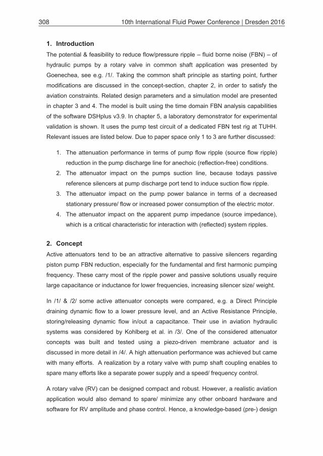
silencer solutions on aircrafts – in Figure 1 shown with the proposed alternative
concept – two technical realizations of the concept are given in Figure 2.
Figure 1: Fluid borne noise (FBN) reduction for aviation hydraulic pumps
The two technical realizations – Figure 2 – of the proposed active attenuator concept
represent promising baseline candidates for an aviation specific application. That
means a safety critical application where also failure cases of the RV are taken into
account, like a stationary pressure drop due to RV sealing wear-out or burst. In that
case, one or multiple switching valves (see SW or SW1/2) would have to disconnect
the RV from the pump discharge line. The remaining components of the assembly
would have to provide a minimum FBN attenuation performance until the next aircraft
maintenance. E.g. for the shown Direct (Drain) Principle, the connection line length (L1)
has to be designed such, that the connection line itself acts like a passive side branch
resonator (SW is closed) for the desired pumping frequencies during RV failure.
Group F - Pumps | Paper F-4 309
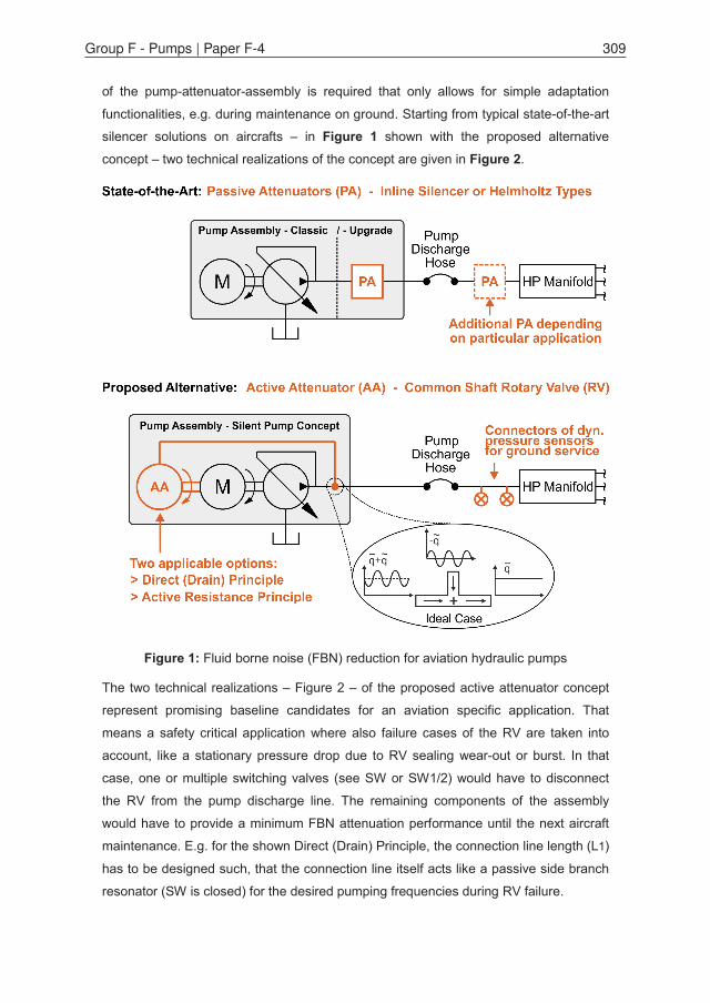
Figure 2: Considered technical realizations of the Silent Pump Concept and primary effect of dedicated tuning parameters on FBN (bold arrows)
3. Design It is assumed that the RV ripple amplitude and phase are adjustable parameters acc. to
Figure 2 during aircraft ground service. So the RV connection line length (L1/2 or LA/B)
to Point “A” – and also the pump line length to Point “A” – become key preliminary
design parameters of the assembly. This is not only for above mentioned RV failure
cases. During normal operation, these lengths have great influence on the ripple phase
of the respective ripple sources at Point “A”. This fact will remain for any active
attenuator assembly acc. to Figure 2, where the RV is assumed as an add-on feature
310 10th International Fluid Power Conference | Dresden 2016

for existing pumps and not yet as an integrated feature inside the housing of future
“smart pumps” (negligible lengths). The relevant relations can be taken from a general
solution of the Helmholtz equations /5/:
(1)
= (2)
In eq. (1), denotes a flow wave along a line, a pressure wave in positive
x-direction (progressive) and in negative x-direction (regressive), all travel with
speed of sound in the fluid. & represent phase shifts increasing with
distance and hence wave motion along the line. & are complex numbers for the
line end boundary conditions, e.g. for pump & rotary valve. is the characteristic pipe
impedance. In eq. (2), the progressive part of eq. (1) is shown in detail. It is an
important design equation for the proposed concepts: If of pump & RV have
the same amplitudes but are in anti-phase at intersection point A, than no progressive
wave remains in a common discharge line and also no regressive (reflected) wave.
4. Simulation Model The simulation models were built using the software DSHplus v3.9, see e.g. Figure 3.
Figure 3: Model for Direct Drain Principle in DSHplus acc. to test rig setup (Figure 6/7)
Group F - Pumps | Paper F-4 311

Simulation and test results are limited here to the Direct Drain Principle, Figure 2, due
to limited paper space. Besides, it was considered to be the most simple & compact
technical realization, and hence to be most attractive one for an aviation application.
The Distributed Parameter Hydraulic Toolbox was applied which allows for ripple/wave
investigation in time domain. The element discretization (discharge line pipe elements),
Fig.3, is chosen acc. to a test rig to account for its sensor spacing, pipe diameters etc.
The noise sources can be represented in multiple ways. The pump can be given by
Function Generators to build sinusoidal signals. They form the flow ripple input of an
open-ended pipe model ( ). Such flow ripple sources were also
built from Pump Characteristic Models (look up tables, e.g. test data). Figure 4 gives
simulation results for the connection line length of pump ( ) & rotary valve ( ). The
three markers in Figure 4 (O, L1, L2) are related to the experimental setup below.
Figure 4: Simulation results for 0(/1). order ripple frequency in the discharge test line
Starting from a reference amplitude of approx. 3 bar (pump acting alone), attenuation is
achieved in the blue marked areas as function of the connection line lengths. Of
course, suitable lengths depend on the desired tuning frequency (see qualitatively the
impact of the 1. order instead of the 0. order, Fig 2). Note the studied aviation pump is
a constant speed pump, which helps to find suitable connection pipe lengths via simple
optimization algorithms (e.g. MATLAB pattern search). Fluid parameters have a minor
impact on the lengths, because the mean pressure is constant & temperature variation
is small. Here, the fluid Skydrol 500B4 is applied with .
312 10th International Fluid Power Conference | Dresden 2016

5. Experimental Setup The utilized noise test rig at TUHH follows dedicated ISO- standards, ISO 15086-1/2/3
& ISO 10767-1/2/3. Procedures in /7/, /8/ & /9/ are also included. The key equipment
features (1.) test pipes with multiple dynamic pressure transducers for progressive/
regressive wave detection & (2.) test ripple sources, here rotary valves (RV), Figure 5.
Figure 5: In-house rotary valve design at TUHH, more details available in /6/
The RV shaft speed controls the RV ripple fundamental frequency. The sleeve angle
adjusts the ripple phase. The ripple shape is adjusted by the sleeve axial position (e).
The amplitude is set by a needle valve that sets the lower pressure level for the RV. In
the presented study, the RV is part of the component under test (EMP+RV), Figure 6
and Figure 7. The needle valve is located in Load Block 2. As mentioned before,
simulation and test results are limited here to the Direct Drain Principle, Figure 2, due
to limited paper space. Besides, this principle is the most simple & compact technical
realization, and hence assumed to be more attractive for an aviation application.
6. Study Cases
6.1. Flow Ripple in Discharge Line In Figure 4, marker O shows an optimal line combination. The test rig geometry did not
allow this. If the pump line is minimal, , than is the
shortest RV length, marker L1. It provides fair attenuation for 0. & 1. order, Fig. 4, while
increases ripple. These expectations match test results for L1 &
L2, Figure 8. Here, flow ripple are shown and the influence of RV angles is given.
Noticeable attenuation is achieved even with none-optimal connection line lengths. The
pump alone would have amplitudes of 1.5 L/min for 0. Order and 1.0 L/min for 1. Order.
Group F - Pumps | Paper F-4 313

Figure 6: Hydraulic Diagram of the experimental setup for Direct Drain Principle
Figure 7: Picture of the experimental setup; pump test circuit of noise test rig at TUHH
314 10th International Fluid Power Conference | Dresden 2016

Figure 8: Experimental source flow ripple results for different RV connection line lengths (L1/ L2) and RV phase angels – Results for pump discharge line
Under the assumption of zero phase difference between pump and RV, the influence of
phase changes due to the line lengths is shown in Figure 9 for 1. Order acc. to eq. (2).
It can be seen that L1 would be an almost optimal RV line length, if . Because
this is not the case, the optimal lengths for RV are O1/2/3 to cancel the pump ripple.
Figure 9: Analytical discussion of the source flow ripple results for a given/fixed pump pipe length (LP) and a variable rotary valve connection pipe length (LRV)
Group F - Pumps | Paper F-4 315

6.2. Flow Ripple in Suction Line From typical passive silencers in the pump discharge line it is known that their blocked/
reflected ripples travel partially back to the pump and into the pumps suction line.
Hence, passive silencers increase the pumps vibration load and cavitation risk at its
suction port. Both reduce life time & reliability. So, an investigation of suction line ripple
is introduced as indicator for pump (+ RV) suffering from its own fluid borne noise.
Corresponding to Figure 8, suction line test results are given in Figure 10. Similar to
passive silencers, the main impact is at lowest frequency order(s), for both, connection
line lengths & RV phase. The RV phase has the greater impact but with opposing trend
to the results in Figure 8. So “L1, RVphase=270deg” tends to be the best in the
discharge line, but the worst in the suction line. In case of L2 it is quite similar. This has
multiple reasons related to the pump impedance and the lower pressure level of 3 bars
in the suction line (different fluid properties). This should always be taken into account.
Figure 10: Experimental source flow ripple results for different RV connection line lengths (L1/ L2) and RV phase angels – Results for pump suction line
6.3. Overall Power Balance For the Direct Drain Principle the RV ripple power is taken from the fluid. A separate
power supply is spared, but means a small decrease of hydraulic power regarding
pump mean pressure/flow characteristic. The mechanical power to drive the RV shaft &
the change of electrical input power are negligible. In cruise condition – mean pressure
~200 bar & consumer flow ~5 L/min – the RV drain flow is ~3 L/min to achieve required
amplitudes. This is ~10% of the pump nominal flow, ~30 L/min, and is tolerable up to a
consumer flow of 25 L/min. Beyond, the mean pressure will drop below required limits.
316 10th International Fluid Power Conference | Dresden 2016

7. Discussion The connection line lengths of pump and RV to an intersection point A were highlighted
as key (pre-) design parameters for the proposed active noise attenuation. The line
lengths have strong impact on the noise phase at point A & hence on the attenuation
performance. Although other parameters impact the phase, e.g. shaft speed & fluid
properties, their impact is minor: A constant pressure hydraulic system – with means of
temperature control – keeps the fluid properties in small limits. Besides, a constant
speed electric motor pump was studied. If a variable speed pump/motor is intended,
e.g. an engine driven pump, length-tuning to a major operating point, is recommended.
Safety valves (SW) can reduce the RV impact outside this operating point, so passive
side branch attenuation would remain of the connection line, Fig. 2, L1. Phase issues
due to connection line lengths will vanish if active attenuation is integrated in future
smart pumps. The concept here can serve as add-on for existing pumps, Figure 11.
Figure 11: CAD assembly of a more compact laboratory prototype, moving the proposed attenuation concept towards an add-on feature for existing pumps
8. Conclusion Active attenuation is known for high fluid borne noise reduction performance. It is
considered for the fundamental & first harmonic frequency of pumps. These carry most
of the noise power, and passive silencers require large capacitance/ inductance in the
lower frequency range, increasing silencer size/ weight. This is an impact on aircraft
production/ operation costs. Constraints related to flight performance & safety demand
compact, robust & low-cost equipment. Hence, the paper focused challenges to get
active attenuation drastically simple, but competitive in performance to passive
silencers. Realistic concepts were discussed by simulation & test. The feasibility was
shown. Control equipment is minimized by knowledge-based pre-design. It is referred
to e.g. /10/ if RT-control (with FIR-filters, LMS-analysis, etc.) is required & e.g. to /11/ if
time domain FBN modelling of pumps is desired including the pump impedance.
Group F - Pumps | Paper F-4 317

9. References /1/ Goenechea, Eneko: Aktive Pulsationsminderung – Funktionsweise einer
neuartigen Sekundärmaßnahme in hydraulischen Systemen. O+P Ölhydraulik
und Pneumatik 9/2006, Vereinigte Fachverlage GmbH, Mainz, Germany, 2006
/2/ Goenechea, Eneko: Mechatronische Systeme zur Pulsationsminderung
hydrostatischer Verdrängereinheiten. PhD-Thesis, Institute for Fluid Power
Drives and Controls (IFAS), RWTH University Aachen, Germany, 2007
/3/ Kohlberg, Michel; Thielecke, Frank; Heise, Ulrich; Behr, Robert Marinus:
Novel Concepts for Noise Reduction in Aircraft Hydraulic Systems. Deutscher
Luft- und Raumfahrtkongress, Bremen, Germany, September 27-29, 2013
/4/ Lentner, K; Hermle, F; Waitschat, A; Christmann, M; Thielecke, F; Behr, R M:
Piezo-Actuated Hydraulic Transducer for Active Noise Reduction. International
Conference on New Actuators, Bremen, Germany, June 23-25, 2014
/5/ Johnston, N; Tilley, D: Noise in Hydraulic Systems. Course Manuscript, Centre
for Power Transmission and Motion Control, University of Bath, UK, 2013
/6/ Waitschat, A; Thielecke, F; Kloft, P; Nisters, C; Behr, R M; Heise, U: Compact
Fluid-Borne Noise Silencers for Aviation Hydraulic Systems. ASME/Bath
Symposium on Fluid Power & Motion Control, Chicago, USA, Oct 12-14, 2015
/7/ Kojima, E; Yamazaki, T; Edge, K: Development of Standard Testing
Procedure for Experimentally Determining Inherent Source Pulsation Power
Generated by Hyd. Pump. Int. Journal of Fluid Power 10 No 1, pp 27-35, 2009
/8/ Kojima, E; Yu, J; Ichiyanagi, T: Experimental Determining and Theoretical
Predicting of Source Flow Ripple Generated by Fluid Power Piston Pumps.
SAE Off-Highway & Powerplant Congress, Milwaukee, USA, Sept 11-13, 2000
/9/ Ericson, L: On Fluid Power Pump & Motor Design - Tools for Noise Reduction.
PhD-Thesis, Div. Fluid & Mechatronic Systems, Linköping Uni., Sweden, 2011
/10/ Pan, M; Hillis, A; Johnston, N: Active Control of Fluid-borne Noise in Hydraulic
Systems Using In-series and By-pass Structures. UKACC Int. Conference on
Control, CONTROL 2014 - Proceedings, IEEE, pp 355-360, 2014
/11/ Baum, H; Becker, K; Faßbender, A: Hybrid Pump Model for 1D Hydraulic
System Simulation. Fluid Power Conf., Aachen, Germany, March 24-26, 2014
318 10th International Fluid Power Conference | Dresden 2016


![Calculating Ground-Borne Noise From Ground-Borne Vibration ...past.isma-isaac.be/downloads/isma2010/papers/isma2010_0686.pdf · ISO 14837-1 [2]. It explains the mechanisms of excitation](https://img.pdfslide.us/doc/110x75/5ebe3b5bab1ed31a9e2d1a88/calculating-ground-borne-noise-from-ground-borne-vibration-pastisma-isaacbedownloadsisma2010papersisma20100686pdf.jpg)