Embed Size (px)
Citation preview
L * ,
NASA Technical Memorandum 10 0 5 8 1
ACTIVE COOLING DESIGN FOR SCRAMJET
ENGINES USING OPTIMIZATION METHODS
( U A S A - T H - 100581) ACTIVE CCCLlBG DESIGN PCR ~ ~ e - 2 e 6 6 9 SCiiAHJE'I EYGlbiES LSIlG C P T I t 1 9 A ' f I C I flJETHCGS (EASA) 13 F CSCL 2OK
Uaclas G3/39 0135289
Stephen J. Scotti Carl J. Martin Stephen H. Lucas
MARCH 1988
National Aeronautics and Space Adrninlstration
Langley Research Center Hampton, Virginia 23665-5225
https://ntrs.nasa.gov/search.jsp?R=19880011285 2018-06-23T01:05:43+00:00Z
ACTIVE COOLING DESIGN FOR SCRAMJET ENGINES USING OPTIMIZATION METHODS
Stephen J. Scotti NASA Langley Research Center
Hampton, Va. 23665
Carl J. Martin PRC Kentron Inc.
Hampton, Va. 23666
Stephen H. Lucas ViRA Inc.
Hampton, Va. 23666 c
Abstract A methodology for using optimization in designing me-
tallic cooling jackets for scramjet engines is presented. The optimal design minimizes the required coolant flow rate sub- ject to temperature, mechanical-stress, and thermal-fatigue- life constraints on the cooling-jacket panels, and Mach-num- ber and pressure constraints on the coolant exiting the panel. The analytical basis for the methodology is presented, and results for the optimal design of panels are shown to demon- strate its utility.
Nomenclature a =sonic velocity A =surface area aeq A f beq
=equivalent annular plate outer radius =flow area =equivalent annular plate inner radius =coefficients in eqns. (13) and (14) Cl,C?
Cij d Dh D‘ E
f F G h
. L m M N
Ef
Nij
Nf N u P Pr P i-
Re
t T
S
W
2
X a €
- . . =material constants for fatigue calculations =pin base diameter =hydraulic diameter for channel fins =coolant passage volume divided by wetted area =Young’s modulus =frictional energy loss =Fanning friction factor =objective function =vector of constraint functions or their limits =channel height, pin height, specific enthalpy =flow length for pressure drop calculation =coolant mass flow rate =coolant Mach number =number of pin rows in flow direction =number of cycles a t conditions i j
=number of mission cycles before fatigue failure =Nusselt number =coolant pressure =Prandtl number =incident heat flux =pin fillet radius =Reynolds number =channel width, pin spacing =outer wall thickness =temperature =channel wall thickness =distance from entrance of cooling panel =vector of design variables or their limits =coefficient of thermal expansion =strain range
before fatigue failure
Y i j P =coolant density U =stress
=material constants for fatigue calculations
subscrbts i =coolant conditions a t entrance
in,out =coolant conditions at entrance
lim, 1, u pc, pp PI ref =reference conditions inner, outer=inner and outer facesheets of cooling jacket
or exit of a segment
and exit of the panel =limiting value, lower and upper limits =load conditions for fatigue calculations =plastic
Introduction The resurgence of interest in hypersonic flight has spurred
a corresponding interest in high-temperature structures. The extreme heating environments of vehicles such as the Aero- space Plane and the “Orient Express” require an extension of the progress made in the structures research of the last two decades. One of the most demanding challenges in high- temperature, hypersonic structures is the design of the hydro- gen-fueled, scramjet engine for the vehicle. A scramjet engine is an airbreathing propulsion system which combusts a fuel such as hydrogen in a supersonic airstream. Because of the high density and total enthalpy of the air flow, the heating of the structure wetted by the airstream can be extreme. Peak heating rates in the combustor of a scramjet can easily exceed 3000 Btu/ft2-sec, a level which requires an active cooling sys- tem to maintain the walls a t a survivable temperature. The cooling system which has shown the most promise for en- gine cooling applications is a system of hydrogen-fuel-cooled, metallic, surface heat exchangers (cooling jackets) attached directly to the engine primary structure (see reference 1, a summary of the research into convectively cooled structures during the 1960’s and 1970’s).
In the design of most aerospace structures, the design goal is typically a minimum weight design. However in this study, the design goal is to minimize the required flow rate of coolant. The reasons for this choice of design goal follow. Energy balance methods have been used to predict the hy- drogen fuel flow rate required to cool the scramjet engine of a hypersonic vehicle; however even using these simple meth- ods, the coolant requirement exceeds the fuel flow rate for optimum engine performance a t Mach numbers greater than about ten (ref. 2). This increase in fuel flow rate to provide engine cooling has a significant effect on the amount of fuel
a vehicle requires to complete its mission. Viewed a different way, it may cause the required size of a vehicle designed to perform a mission to undergo a large increase. The results found in these past studies are optimistic since the internal performance of the surface heat exchangers (that is, the over- all cooling system effectiveness) has not been considered in determining the cooling requirements for the scramjet engine. Heat exchanger performance along with additional thermal and structural requirements on the cooling-jacket structure may increase cooling needs far above those calculated using a simple energy balance. Since the cooling system is only a minor contributor to the engine weight, but the major fac- tor in determining the required coolant flow rate, this paper presents a method for designing engine cooling jackets and determining coolant conditions which minimizes the required flow rate of coolant.
The cooling-jacket design method of the present study uses numerical optimization as a design tool. Numerical o p timization is a practical approach to the design of cooling- jacket systems since many design requirements can be con- sidered simultaneously. The optimization goal is to design cooling jackets which minimize the required coolant flow rate for specified heating rates. The design must also satisfy d e sign requirements such as material limits on cooling-jacket temperature, stress, and fatigue life as well as limits on cool- ant Mach number and pressure drop through the coolant pas- sages.
Geometries for two cooling-jacket concepts, namely chan- nel-fin and pin-fin concepts, are studied in this application of the design methodology, The approximate analytical meth- ods used to predict performance of these cooling-jacket sys- tems with these geometries and the use of formal optimization to couple the analyses to produce optimum designs are ex- plained. Results of the optimization of a single heated panel are presented for various combinations of materials, heating rates, and inlet pressure limits. The single panel cases demon- strate the applicability of the methodology for cooling-jacket design and for sensitivity analysis with respect to certain d e sign parameters. These cases also illustrate the existence of strong coupling between the different design constraints. Ad- ditionally, some results of a three-panel system of cooling jackets are given to illustrate flow routing effects.
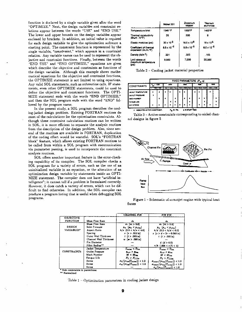
Scramiet and Coolinv-Jacket Geometry DescriDtion A schematic showing the location of a scramjet engine on
the lower surface of a hypersonic vehicle is given in the upper portion of figure 1. From this schematic, the smooth integra- tion of the engine with the vehicle lower surface in front of the engine (the forebody) and behind the engine (the afterbody) is apparent. This integration of vehicle with engine improves vehicle performance.
A conceptual, two-dimensional scramjet engine cross sec- tion is shown in the middle of figure 1. The engine consist of a series of ramps (which may be movable) that merge with the vehicle lower surface, and a cowl which helps capture the air compressed by the vehicle fuselage and the engine ramps. For a fixed flight condition, there are no moving parts in the scramjet engine except for the fuel pumps. Not shown in the figure are the sidewalls which connect the cowl to the ramps to form a twedimensional flow passage. The major compe nents of the engine are the inlet, combustor, and nozzle.
A typical engine ramp heat flux distribution is shown in the lower portion of figure 1. The combustor section experi- ences the highest heat flux. The nozzle and the inlet experi-
ence lower heat fluxes with the inlet having the lowest. Typ- ical ramp heat fluxes assumed for demonstrating the design methodology are 1000 to 2000 Btu/ft2-sec for the combus- tor, 300 Btu/ft2-sec for the nozzle, and 150 Btu/ft2-s& for the inlet. All three components require active cooling. The engine cowl and sidewalls along with portions of the vehicle forebody and afterbody also require active cooling, however, these areas are not considered in the present study since they can be designed using the same procedure as the ramp panels.
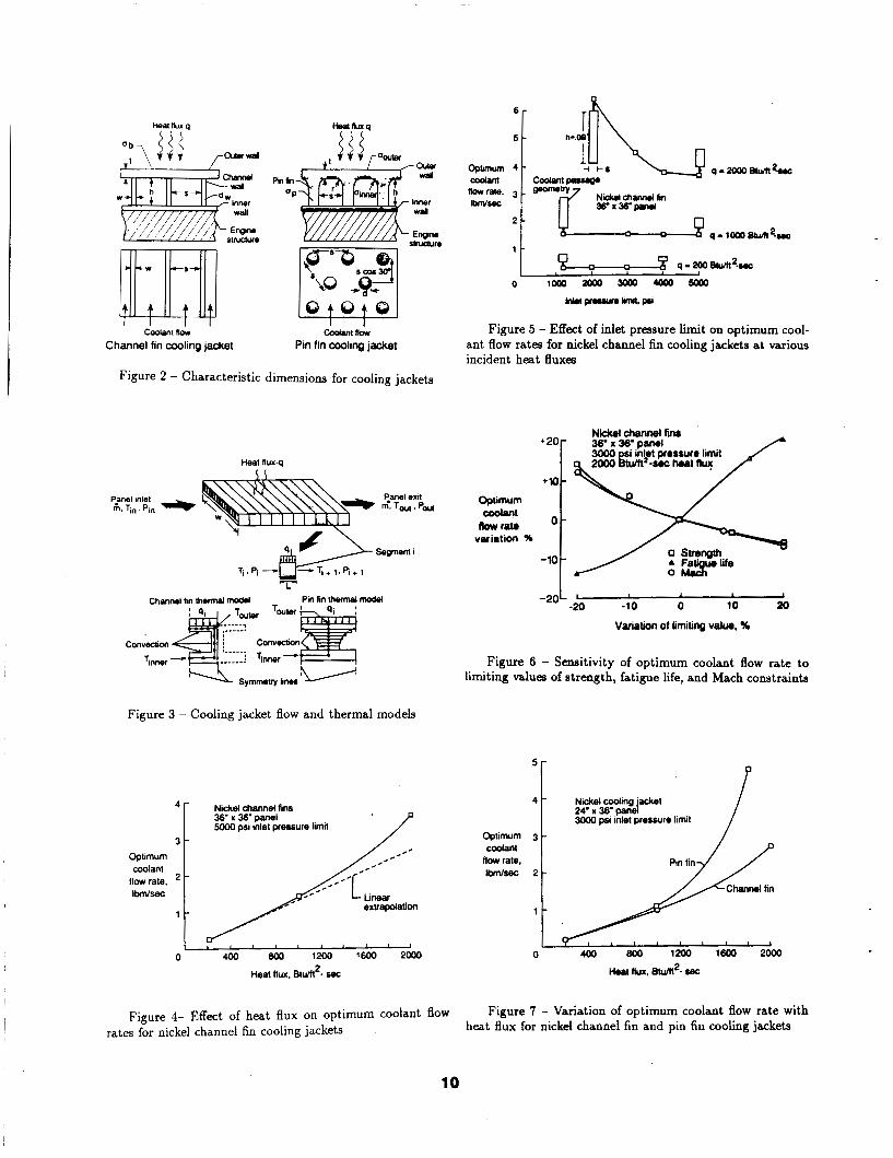
The geometries of channel-fin and pin-fin cooling jackets are illustrated in figure 2. For channel-fin cooling jackets, the geometry can be completely described by the channel width (s), the channel height (h), the channel wall thickness (w), and the outer wall (outer facesheet) thickness ( t ) . Assuming the pins are located at the vertices of equilateral triangles, the geometry of pin-fin cooling jackets is characterized by the pin spacing (s), the pin base diameter ( d ) , the pin height (h), the pin fillet radius (r), and the outer wall thickness ( t ) .
Analvtical Basis for Desinn Methodolonv This section presents a brief description of the analytical
models used to evaluate the performance of the cooled pan- els. The design requirements which must be satisfied in the design methodology are limits on material temperature, cool- ant pressure drop and Mach number, cooling-jacket stress and low-cyciefatigue life. Since numerical optimization requires the repeated evaluation of these quantities, simple and com- putationally efficient models are used. A given cooled panel is divided into segments along the flow length (fig. 3), and the coolant flow conditions, as well as each of the design require ments, are evaluated at the exit of each segment. A brief description of the various analytical models which describe the actively cooled panel performance follows.
Coolant Flow Analvsis Figure 3 illustrates the division of the cooling-jacket panel
into segments of length L for purposes of the analysis. Cool- ant flow and heat flux are assumed to be uniform across the width of the panel, and thus the coolant and structural tem- peratures do not vary across the panel width. Below the panel in figure 3 is a representative segment with entrance temperature Ti and pressure p i . It is subjected to heat flux qi , and the coolant enthalpy rise through the segment is
where A is the segment heated surface area, hi and hi+l are enthalpies at the segment entrance and exit, and m is the coolant mass flow rate. The coolant temperature a t the exit of the segment (Tj+l) is determined using hydrogen gas property routines (ref. 3) which determine gas temperature for given enthalpies and pressure. The relationship used is
Ti+l = f ( h i + l , p i + l ) f ( h i + l r P i ) (2)
The approximate relationship in (2) is valid because the tem- perature-enthalpy relationship is only a weak function of pres- sure, and the pressure drops across segments are small.
The coolant pressure drop across a segment is given by the expression
2
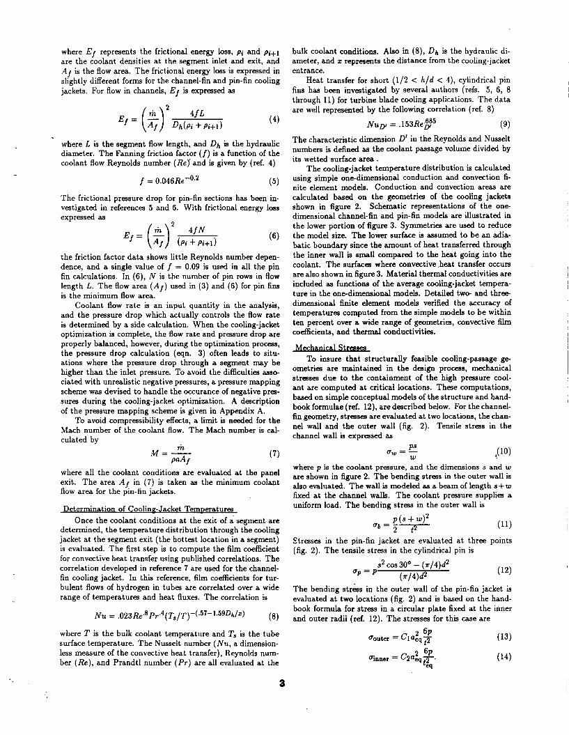
where Ef represents the frictional energy loss, p i and p i+ l are the coolant densities a t the segment inlet and exit, and AI is the flow area. The frictional energy loss is expressed in slightly different forms for the channel-fin and pin-fin cooling jackets. For flow in channels, Ef is expressed as
(4)
where L is the segment flow length, and Dh is the hydraulic diameter. The Fanning friction factor (f) is a function of the coolant flow Reynolds number (Re] and is given by (ref. 4)
f = 0.046Re-0.2 (5)
The frictional pressure drop for pin-fin sections has been in- vestigated in references 5 and 6. With frictional energy loss expressed as
the friction factor data shows little Reynolds number depen- dence, and a single value of f = 0.09 is used in all the pin fin calculations. In (6), N is the number of pin rows in flow length L. The flow area ( A f ) used in (3) and (6) for pin fins is the minimum flow area.
Coolant flow rate is an input quantity in the analysis, and the pressure drop which actually controls the flow rate is determined by a side calculation. When the cooling-jacket optimization is complete, the flow rate and pressure drop are properly balanced, however, during the optimization process, the pressure drop calculation (eqn. 3) often leads to situ- ations where the pressure drop through a segment may be higher than the inlet pressure. To avoid the difficulties asso- ciated with unrealistic negative pressures, a pressure mapping scheme was devised to handle the occurance of negative pres- sures during the cooling-jacket optimization. A description of the pressure mapping scheme is given in Appendix A.
To avoid compressibility effects, a limit is needed for the Mach number of the coolant flow. The Mach number is cal- culated by
m M = - PaA f (7)
where all the coolant conditions are evaluated at the panel exit. The area A f in (7) is taken as the minimum coolant flow area for the pin-fin jackets.
Determination of Coolinn-Jacket TemDeratures Once the coolant conditions at the exit of a segment are
determined, the temperature distribution through the cooling jacket at the segment exit (the hottest location in a segment) is evaluated. The first step is to compute the film coefficient for convective heat transfer using published correlations. The correlation developed in reference 7 are used for the channel- fin cooling jacket. In this reference, film coefficients for tur- bulent flows of hydrogen in tubes are correlated over a wide range of temperatures and heat fluxes. The correlation is
where T is the bulk coolant temperature and Ts is the tube surface temperature. The Nusselt number (Nu , a dimension- less measure of the convective heat transfer), Reynolds num- ber (Re) , and Prandtl number (Pr) are all evaluated at the
bulk coolant conditions. Also in (8), Dh is the hydraulic di- ameter, and I represents the distance from the cooling-jacket entrance.
Heat transfer for short (112 < h/d < 4), cylindrical pin fins has been investigated by several authors (refs. 5, 6, 8 through 11) for turbine blade cooling applications. The data are well represented by the following correlation (ref. 8)
(9) The characteristic dimension D' in the Reynolds and Nusselt numbers is defined as the coolant passage volume divided by its wetted surface area .
The cooling-jacket temperature distribution is calculated using simple one-dimensional conduction and convection fi- nite element models. Conduction and convection areas are calculated based on the geometries of the cooling jackets shown in figure 2. Schematic representations of the one- dimensional channel-fin and pin-fin models are illustrated in the lower portion of figure 3. Symmetries are used to reduce the model size. The lower surface is assumed to be an adia- batic boundary since the amount of heat transferred through the inner wall is small compared to the heat going into the coolant. The surfaces where convective .heat transfer occurs are also shown in figure 3. Material thermal conductivities are included as functions of the average cooling-jacket tempera- ture in the one-dimensional models. Detailed two- and three- dimensional finite element models verified the accuracy of temperatures computed from the simple models to be within ten percent over a wide range of geometries, convective film coefficients, and thermal conductivities.
Mechanical S b s es To insure that structurally feasible cooling-passage ge-
ometries are maintained in the design process, mechanical stresses due to the containment of the high pressure cool- ant are computed a t critical locations. These computations, based on simple conceptual models of the structure and hand- book formulae (ref. 12), are described below. For the channel- fin geometry, stresses are evaluated at two locations, the chan- nel wall and the outer wall (fig. 2). Tensile stress in the channel wall is expressed as
where p is the coolant pressure, and the dimensions s and w are shown in figure 2. The bending stress in the outer wall is also evaluated. The wall is modeled as a beam of length s+ w fixed at the channel walls. The coolant pressure supplies a uniform load. The bending stress in the outer wall is
$tresses in the pin-fin jacket are evaluated at three points (fig. 2). The tensile stress in the cylindrical pin is
s2 cos 30' - (r/4)d2 ( ~ / 4 ) &
up = P
The bending stress in the outer wall of the pin-fin jacket is evaluated at two locations (fig. 2) and is based on the hand- book formula for stress in a circular plate fixed at the inner and outer radii (ref. 12). The stresses for this case are
a
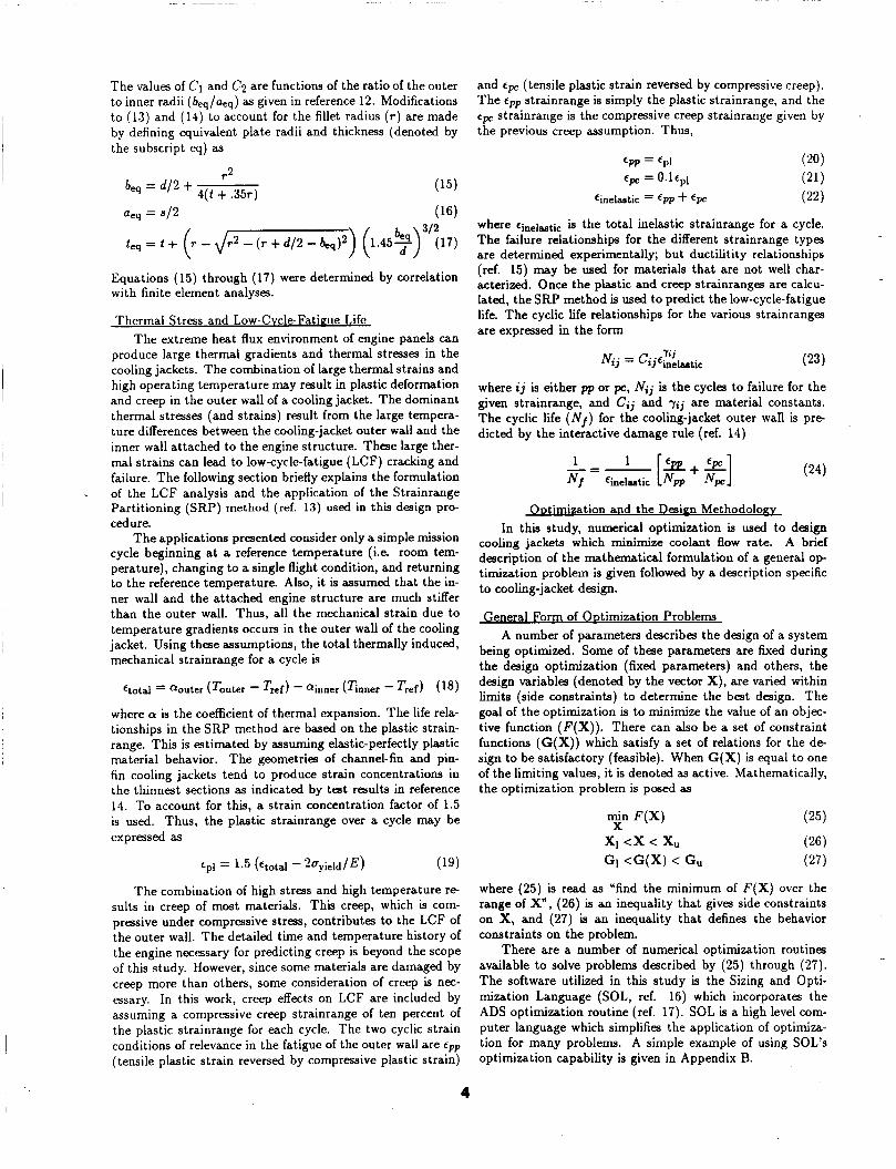
The values of C1 and C2 are functions of the ratio of the outer to inner radii (beq/aeq) as given in reference 12. Modifications to (13) and (14) to account for the fillet radius ( r ) are made by defining equivalent plate radii and thickness (denoted by
and cpc (tensile plastic strain reversed by compressive creep). The strainrange is simply the plastic strainrange, and the epc strainrange is the compressive creep strainrange given by the previous creep assumption. Thus,
PP.
the subscript &) as ‘ p p = ‘PI
‘pc = 0.lep1
‘inelastic = ‘PP + ‘pc .. .
where ‘inelastie is the total inelastic strainrange for a cycle.
are determined experimentally; but ductilitity relationships
aeq = 912 (16)
r - Jr2 - ( r + d/2 - hq)2) (l.45?)3’?17) The failure relationships for the different strainrange types
(ref. 15) may be Led for materials that are-not well char- acterized. Once the plastic and creep strainranges are calcu- lated, the SRP method is used to predict the low-cycle-fatigue
Equations (15) through (17) were determined by correlation with finite element analyses.
Thermal Stress and Low-Cvcle-Fatigue Life life. The cyclic life relationships for the various strainranges are expressed in the form The extreme heat flux environment of engine panels can
produce large thermal gradients and thermal stresses in the cooling jackets. The combination of large thermal strains and high operating temperature may result in plastic deformation and creep in the outer wall of a cooling jacket. The dominant thermal stresses (and strains) result from the large tempera- ture differences between the cooling-jacket outer wall and the inner wall attached to the engine structure. These large ther- mal strains can lead to low-cycle-fatigue (LCF) cracking and failure. The following section briefly explains the formulation of the LCF analysis and the application of the Strainrange Partitioning (SRP) method (ref. 13) used in this design pro- cedure.
The applications presented consider only a simple mission cycle beginning at a reference temperature (i.e. room tem- perature), changing to a single flight condition, and returning to the reference temperature. Also, it is assumed that the in- ner wall and the attached engine structure are much stiffer than the outer wall. Thus, all the mechanical strain due to temperature gradients occurs in the outer wall of the cooling jacket. Using these assumptions, the total thermally induced, mechanical strainrange for a cycle is
.
€total aouter (Touter - Tref) - ainner (Tnner - Tref) (18)
where a is the coefficient of thermal expansion. The life rela- tionships in the SRP method are based on the plastic strain- range. This is estimated by assuming elastic-perfectly plastic material behavior. The geometries of channel-fin and pin- fin cooling jackets tend to produce strain concentrations in the thinnest sections as indicated by test results in reference 14. To account for this, a strain concentration factor of 1.5 is used. Thus, the plastic strainrange over a cycle may be expressed as
The combination of high stress and high temperature re- sults in creep of most materials. This creep, which is com- pressive under compressive stress, contributes to the LCF of the outer wall. The detailed time and temperature history of the engine necessary for predicting creep is beyond the scope of this study. However, since some materials are damaged by creep more than others, some consideration of creep is nec- essary. In this work, creep effects on LCF are included by assuming a compressive creep strainrange of ten percent of the plastic strainrange for each cycle. The two cyclic strain conditions of relevance in the fatigue of the outer wall are e p p (tensile plastic strain reversed by compressive plastic strain)
where ij is either p p or pc, Ni, is the cycles to failure for the given strainrange, and Ci, and rij are material constants. The cyclic life (Nf) for the cooling-jacket outer wall is pre- dicted by the interactive damage rule (ref. 14)
. . ODtirmzation and the Desinn Methodolonv In this study, numerical optimization is used to design
cooling jackets which minimize coolant flow rate. A brief description of the mathematical formulation of a general o p timization problem is given followed by a description specific to cooling-jacket design.
General Form of ODtimization Problems A number of parameters describes the design of a system
being optimized. Some of these parameters are fixed during the design optimization (fixed parameters) and others, the design variables (denoted by the vector X ) , are varied within limits (side constraints) to determine the best design. The goal of the optimization is to minimize the value of an objec- tive function ( F ( X ) ) . There can also be a set of constraint functions (G(X)) which satisfy a set of relations for the d e sign to be satisfactory (feasible). When G ( X ) is equal to one of the limiting values, it is denoted as active. Mathematically, the optimization problem is posed as
min F ( X ) X
XI <x < x u
GI < G ( X ) < G,
where (25) is read as Yind the minimum of F ( X ) over the range of X “ , (26) is an inequality that gives side constraints on X, and (27) is an inequality that defines the behavior constraints on the problem.
There are a number of numerical optimization routines available to solve problems described by (25) through (27). The software utilized in this study is the Sizing and Opti- mization Language (SOL, ref. 16) which incorporates the ADS optimization routine (ref. 17). SOL is a high level com- puter language which simplifies the application of optimiza- tion for many problems. A simple example of using SOL’S optimization capability is given in Appendix B.
4
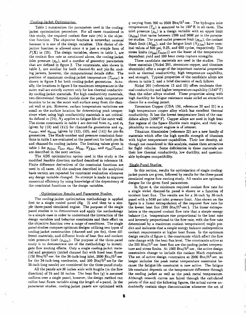
CoolinF-Jacket ODtimization Table 1 summarizes the parameters used in the cooling-
jacket optimization procedure. For all cases considered in this study, the required coolant flow rate (m) is the objec- tive function. The objective function is somewhat unusual because it is one of the design variables. This choice of ob- jective function is allowed since it is just a simple form of F ( X ) in (25). The design variables, shown in table 1, are the coolant flow rate as mentioned above, the cooling-jacket inlet pressure (pin), and a number of geometry parameters that are defined in figure 2. The constraints, also shown in table 1, are similiar for both channel-fin and pin-fin cool- ing jackets, however, the computational details differ. The position of maximum cooling-jacket temperature (Touter) is shown in figure 3 for both cooling-jacket geometries. Actu- ally, the locations in figure 3 for maximum temperature in the outer wall are strictly correct only for low thermal conductiv- ity cooling-jacket materials. For high conductivity materials, two-dimensional thermal models show the peak temperature location to be on the outer wall surface away from the chan- nel wall or pin. However, surface temperature variations are small so the surface location for determining peak temper- ature when using high conductivity materials is not critical. As defined in (24), N/ applies to fatigue life of the outer wall. The stress constraints in table 1 are derived from ow and bb
(given by (10) and (11)) for channel-fin geometries and op, Oouter, and uinner (given by (12), (13), and (14)) for pin-fin geometries. The Mach-number and pressure constraint func- tions in table 1 are evaluated a t the panel exit for both pin-fin and channel-fin cooling jackets. The limiting values given in table 1 for Pulim, q i m , Plimr M i m l N/,lim, and qim(Touter1 are described in the next section.
The ADS optimization option used in this study is the modified feasible direction method described in reference 18. Finite difference derivatives of the constraint functions are used in all cases. All the analyses described in the analytical basis section are repeated for constraint evaluation whenever any design variable changed. No attempt is made to improve numerical efficiency by using knowledge of the dependency of the constraint functions on the design variables.
-
ODtimization Results and Parameter Studies The cooling-jacket optimization methodology is applied
first to a single cooled panel (fig. 3) and then to a sim- ple three-panel simulated engine. The purpose of the single panel studies is to demonstrate and apply the methodology to a simple case in order to understand the interaction of the design variables and behavior constraints and their effect on the objective function over a range of conditions. The single panel studies compare optimum designs utilizing two types of cooling-jacket construction (channel and pin fin), three dif- ferent materials, and different levels of heat flux and coolant inlet pressure limit (pulim). The purpose of the three-panel study is to demonstrate use of the methodology to investi- gate flow routing effects. Only a single cooling-jacket mate- rial and geometry (nickel channel fin) with fixed heat fluxes (150 Btu/ft2-sec for the 36-inch-long inlet, 2000 Btu/ft2-sec for the 24-inch-long combustor, and 300 Btu/ft2-sec for the 36-inch-long nozzle) are considered for the three-panel study.
All the panels are 36 inches wide with lengths (in the flow direction) of 24 and 36 inches. The heat flux (q ) is assumed uniform over a single panel, however, the design method can utilize heat fluxes variable along the length of a panel. In the parameter studies, cooling-jacket panels are optimized with
q varying from 200 to 2000 Btu/ft2-sec. The hydrogen inlet temperature (Tin) is assumed to be 100' R in all cases. The inlet pressure (pin) is a design variable with an upper, limit (pulim) that varies between 1200 and 5000 psi in the parame- ter studies. The panel outlet pressure limit (mim), the coolant Mach limit (Mlim), and the fatigue limit (Nf,lim) have nom- inal values of 600 psi, 0.25, and 600 cycles, respectively. The stress limits (qim(Touter)) are the lesser of the temperature dependent yield and 100 hour creep rupture strengths.
Three candidate materials are used in the studies. The three materials (Nickel 201, zirconium copper, and titanium aluminide) offer a range of the important material properties such as thermal conductivity, high temperature capability, and strength. Typical properties of the candidate alloys are shown in table 2, and a brief discussion of each follows.
Nickel 201 (references 13 and 19) offers moderate ther- mal conductivity and higher temperature capability (1540' F) than the other alloys studied. These properties along with high ductility for fatigue resistance make nickel an attractive choice for a cooling jacket.
Zirconium Copper (CDA 150, references 20 and 21) is a high temperature copper alloy which has excellent thermal conductivity. It has the lowest temperature limit of the can- didate alloys (1000' F). Copper alloys are used in high heat flux regions of the Space Shuttle main engine, and their ap- plicability to scramjet enginea is of interest.
Titanium Aluminides (reference 22) are a new family of materials which offer the high specific strength of titanium with higher temperature capabilities. Their low density, al- though not considered in this analysis, makes them attractive for flight vehicles. Some deficiencies in these materials are their low thermal conductivity, low ductility, and question- able hydrogen compatibility.
Single-Panel Studies In this section, results for optimization of single cooling-
jacket panels are given, followed by results for the three-panel simulated engine flow routing study. All results are optimum designs for the given fixed parameters.
In figure 4, the minimum required coolant flow rate for a single nickel channel-fin panel is shown as a function of incident heat flux. The results are for a 36-inch by 36-inch panel with a 5000 psi inlet pressure limit. Also shown on the figure is a linear extrapolation of the required flow rate for the lowest heat flux (200 Btu/ft2-sec). The linear extrapo- lation is the required coolant flow rate that a simple energy balance (i.e. temperature rise proportional to the heat rate and inversely proportional to the flow rate, with the flow rate determined by a maximum coolant temperature) might pre- dict and indicates that a simple energy balance underpredicts coolant requirements a t higher heat fluxes. In the optimum design results of figure 4, the constraints which affect the flow rate change with the heat flux level. The constraints active a t the 200 Btu/ft2-sec heat flux are the cooling-jacket tempera- ture and stress limits. At 1000 Btu/ft2-sec, the active design constraints change to include the coolant Mach constraint. The set of active design constraints at 2000 Btu/ft2-sec no longer includes the peak metal temperature constraint be- cause the fatigue-life constraint is now active. The fatigue life constaint depends on the temperature difference through the cooling jacket as well as the peak metal temperature. Although smooth curves are faired through the calculated points of this and the following figures, the actual curves un- doubtedly contain slope discontinuities whenever the set of
5
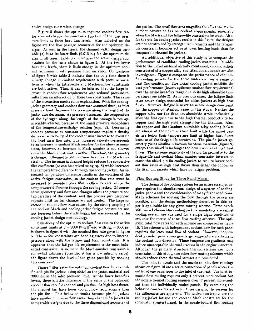
active design constraints change. Figure 5 shows the optimum required coolant flow rate
for a nickel channel-fin panel as a function of the inlet pres- sure limit a t three heat flux levels. Also included on the figure are the flow passage geometries for the optimum de- signs. As seen in the figure, the channel width design vari- able (s) is a t its lower limit (0.015in.) for the optimum de- sign in all cases. Table 3 summarizes the active design con- straints for the cases shown in figure 5. At the two lower heat flux levels, there is little change in the optimum cool- ant requirement with pressure limit variation. Comparisons of figure 5 with table 3 indicate that the only time there is a large change in coolant requirement with pressure varia- tions is when the fatigue-life and Mach-number constraints are both active. Thus, it can be inferred that the large in- crease in coolant flow requirement with reduced pressure re- sults from an interaction of these two constraints. The cause of the interaction merits some explanation. With the cooling- jacket geometry and coolant flow rate assumed fixed, as inlet pressure limit decreases the pressure along the length of the jacket also decreases. As pressure decreases, the temperature of the hydrogen along the length of the passage is not ap- preciably affected because of the small pressure dependence of the temperature-enthalpy relation (eqn. 2). Decreasing coolant pressure a t constant temperature implies a density decrease, so velocity of the coolant must increase to maintain thc fixed mass flow rate. The increased velocity corresponds to an increase in coolant Mach number for the above assump- tions, however, an increase in Mach number is not allowed since the Mach constraint is active. Therefore, the geometry is changed. Channel height increases to enforce the Mach con- straint. The increase in channel height reduces the convective film coefficient (as can be derived using eq. 8) which increases the temperature difference through the cooling jacket. An in- creased temperature difference results in the violation of the active fatigue constraint, so the coolant flow rate must be increased to provide higher film coefficients and reduce the temperature difference through the cooling jacket. Of course, these geometry and flow rate changes affect the pressure and temperature of the coolant, and the process just described repeats until further changes are not needed. The large in- crease in coolant flow rate caused by the strong coupling of the coolant Mach and cooling-jacket fatigue constraints was not foreseen before the study began but was revealed by the cooling-jacket design methodology.
Sensitivity of the optimum coolant flow rate to the active constraint limits a t q = 2000 Btu/ft2-sec with fin = 3000 psi is shown in figure 6 with the nominal flow rate given in figure 5. The active constraints are bending stress due to internal pressure along with the fatigue and Mach constraints. It is apparent that the fatigue life requirement is the most influ- ential constraint. Also, since the Mach-number constraint is somewhat arbitrary (provided it has a low subsonic value), the figure shows the level of the gains possible by relaxing this constraint.
Figure 7 illustrates the optimum coolant flow for channel- fin and pin-fin jackets using nickel as the jacket material and 3000 psi as the inlet pressure Limit. At the lower heat-flux levels, there is little difference in the value of the optimum coolant flow rate for channel and pin fins. At high heat fluxes, the channel fins have lower coolant flow requirements than the pin fins. This behavior results because pin-fin jackets have smaller minimum flow areas than channel-fin jackets in comparable designs due to the three-dimensional geometry of
.
the pin fin. The small flow area magnifies the effect the Mach- number constraint has on coolant requirements, especially when the Mach and the fatigue-life constraints interact. Also, for the pin-fin cooling jacket results in this figure, the designs are not constrained by strength requirements and the fatigue- life constraint becomes active a t lower heating loads than for comparable channel-fin jackets.
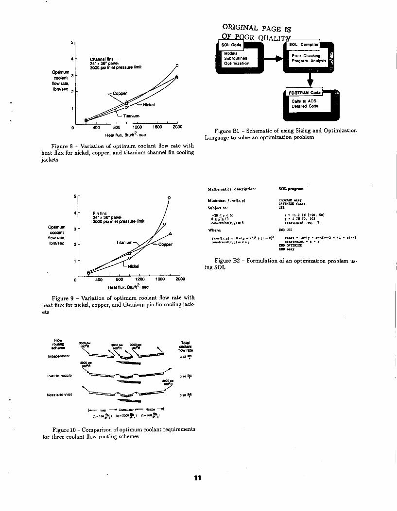
An additional objective of this study is to compare the performance of candidate cooling-jacket materials. In addi- tion to the nickel material already mentioned, cooling jackets constructed of a copper allc;. and titanium aluminide are also investigated. Figure 8 compares the performance of channel- fin cooling jackets for the three materials over a range of heat-flux conditions. The nickel cooling jacket exhibits the best performance (lowest optimum coolant flow requirement) over the entire heat-flux range due to its high allowable tem- perature (see table 2). As in previous cases, the fatigue limit is an active design constraint for nickel jackets a t high heat fluxes. However, fatigue is never an active design constraint for the copper or titanium cases in this study. Neither the copper alloy nor the titanium aluminide strain inelastically after the first cycle due to the high thermal conductivity for copper and the high yield strength for the titanium. Also, the copper and the titanium aluminide alloy cooling jackets are always at their temperature limit while the nickel pan- els are below their temperature limit a t higher heat fluxes because of the fatigue-life constraint. The pin-fin jacket ge- ometry yields similiar behaviors for these materials (figure 9) except that nickel is no longer the best material a t high heat fluxes. The extreme sensitivity of the pin-fin geometry to the fatigue-life and coolant Mach-number constraint interaction cause the nickel pin-fin cooling jacket to require larger cool- ant flow rates a t high heat fluxes than either the copper or the titanium jackets which have no fatigue problem.
Flow-Routine Study for Three-Panel Model The design of the cooling system for an entire scramjet en-
gine requires the simultaneous design of a system of cooling- jacket panels and the consideration of many flight conditions. Many schemes for routing the flow through the panels are possible, and the design methodology described in this pa- per is applicable for any given routing scheme. Three panels with nickel channel-fin cooling jackets simulating a scramjet cooling system are analyzed for a single flight condition to evaluate the merits of three flow routing schemes. The opti- mum total flow rates for each scheme are compared in figure 10. The scheme with independent coolant flow for each panel requires the least total flow of coolant. However, indepen- dently cooled panels may give large temperature gradients in the coolant flow direction. These temperature gradients may induce unacceptable thermal stresses in the engine structure. Although the primary structure thermal stresses are not a constraint in this study, two other flow routing schemes which should reduce these thermal stresses are considered.
The inlet-to-nozzle and the nozzle-to-inlet flow routings shown on figure 10 are a series connection of panels where the outlet of one panel goes to the inlet of the next. The inlet-to- nozzle flow routing requires only 4 percent more coolant but the nozzle-to-inlet routing requires over 17 percent more cool- ant than the individually cooled panels. By examining the behavior constraints active for these designs, the reasons for the differences are apparent. The active constraints are the cooling-jacket fatigue and coolant Mach constraints for the combustor (center) panel. In the nozzle-to-inlet flow routing
6
case, the coolant flow entering the combustor is a t a higher temperature and a lower pressure than for the inlet-to-nozzle routing case. These conditions require a larger coolant flow rate to satisfy the constraints in the combustor. Similar ef- fects are seen in the single panel cases for reduced inlet prts- sure at a high heat flux level.
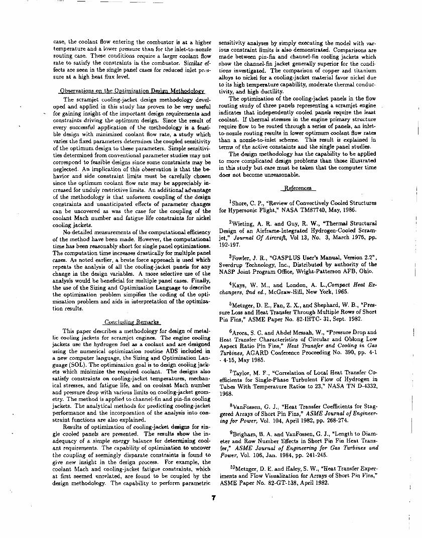
The scramjet cooling-jacket design methodology devel- oped and applied in this study has proven to be very useful for gaining insight of the important design requirements and constraints driving the optimum design. Since the result of every successful application of the methodology is a feasi- ble design with minimized coolant flow rate, a study which varies the fixed parameters determines the coupled sensitivity of the optimum design to these parameters. Simple sensitivi- ties determined from conventional parameter studies may not correspond to feasible designs since some constraints m a y be neglected. An implication of this observation is that the be- havior and side constraint limits must be carefully chosen since the optimum coolant flow rate may be appreciably in- creased for unduly restrictive limits. An additional advantage of the methodology is that unforseen coupling of the design constraints and unanticipated effects of parameter changes can be uncovered as was the case for the coupling of the coolant Mach number and fatigue life constraints for nickel cooling jackets.
No detailed measurements of the computational efficiency of the method have been made. However, the computational time has been reasonably short for single panel optimizations. The computation time increases drastically for multiple panel cases. As noted earlier, a brute force approach is used which repeats the analysis of all the cooling-jacket panels for any change in the design variables. A more selective use of the analysis would be beneficial for multiple panel cases. Finally, the use of the Sizing and Optimization Language to describe the optimization problem simpifies the coding of the opti- mization problem and aids in interpretation of the optimiza- tion results.
-
Conc I ud i n e Remarks This paper describes a methodology for design of metal-
lic cooling jackets for scramjet engines. The engine cooling jackets use the hydrogen fuel as a coolant and are designed using the numerical optimization routine ADS included in a new computer language, the Sizing and Optimization Lan- guage (SOL). The optimization goal is to design cooling jack- ets which minimize the required coolant. The designs also satisfy constraints on cooling-jacket temperatures, mechan- ical stresses, and fatigue life, and on coolant Mach number and pressure drop with various limits on cooling-jacket geom- etry. The method is applied to channel-fin and pin-fin cooling jackets. The analytical methods for predicting cooling-jacket performance and the incorporation of the analysis into con- straint functions are also explained.
Results of optimization of cooling-jacket designs for sin- gle cooled panels are presented. The results show the in- adequacy of a simple energy balance for determining cool- ant requirements. The capability of optimization to uncover the coupling of seemingly disparate constraints is found to give new insight in the design process. For example, the coolant Mach and cooling-jacket fatigue constraints, which at first seemed unrelated, are found to be coupled by the design methodology. The capability to perform parametric
sensitivity analyses by simply executing the model with var- ious constraint limits is also demonstrated. Comparisons are made between pin-fin and channel-fin cooling jackets which show the channel-fin jacket generally superior for the condi- tions investigated. The comparison of copper and titanium alloys to nickel for a cooling-jacket material favor nickel due to its high temperature capability, moderate thermal conduc- tivity, and high ductility.
The optimization of the cooling-jacket panels in the flow routing study of three panels representing a scramjet engine indicates that independently cooled panels require the least coolant. If thermal stresses in the engine primary structure require flow to be routed through a series of panels, an inlet- to-nozzle routing results in lower optimum coolant flow rates than a nozzle-to-inlet scheme. This result is explained in t e r m of the active constaints and the single panel studies.
The design methodology has the capability to be applied to more complicated design problems than those illustrated in this study but care must be taken that the computer time does not become unreasonable.
References
lShore, C. P., “Review of Convectively Cooled Structures for Hypersonic Flight,” NASA TM87740, May, 1986.
2Wieting, A. R. and Guy, R. W., “Thermal Structural Design of an Airframe-Integrated Hydrogen-Cooled Scram- jet,” Journal Of Aircraj?, Vol 13, No. 3, March 1976, pp. 192-197.
3Fowler, J. R., “GASPLUS User’s Manual, Vemion 2.2”, Sverdrup Technology, Inc., Distributed by authority of the NASP Joint Program Office, Wright-Pattenon AFB, Ohio.
4Kays, W. M., and London, A. L.,Cornpact Heat Ez- changers, 2nd ed., McGraw-Hill, New York, 1965.
5Metzger, D. E., Fan, 2. X., and Shephard, W. B., “Pres- sure Loss and Heat Transfer Through Multiple Rows of Short Pin Fins,” ASME Paper No. 82-IHTC- 31, Sept. 1982.
6Arora, S. C. and Abdel Messah, W., “Pressure Drop and Heat Transfer Characteristics of Circular and Oblong Low Aspect Ratio Pin Fins,” Heat Transfer and Cooling in Gas Tbrbines, AGARD Conference Proceeding No. 390, pp. 4-1 - 4-15, May 1985.
7Taylor, M. F., “Correlation of Local Heat Transfer Co- efficients for Single-phase Turbulent Flow of Hydrogen in Tubes With Temperature Ratios to 23,” NASA T N D-4332, 1968.
8VanFossen, G. J., “Heat Transfer Coefficients for Stag- gered Arrays of Short Pin Fins,” ASME Journal of Engineer- ing for Power, Vol. 104, April 1982, pp. 268-274.
gBrigham, B. A. and VanFossen, G. J., “Length to Diam- eter and Row Number Effects in Short Pin Fin Heat Trans- fer,” A S M E Journal of Engineering for Gas Turbines and Power, Vol. 106, Jan. 1984, pp. 241-245.
‘OMetzger, D. E. and Haley, S. W., “Heat Transfer Exper- iments and Flow Visualization for Arrays of Short Pin Fins,” ASME Paper No. 82-GT-138, April 1982.
‘lMetzger, D. E., Berry, R. A., and Bronson, J. P., “De- veloping Heat Transfer i n Ducts Witli Staggered Arrays of Short Pin Fins,” ASME Journal of Engineering for Power, Vol 104, April 1982, pp. 701-706.
I2Roark, R. J. ,Fomulas for Stress and Strain, 5th ed., McGraw-Hill, New York, 1975. p. 342.
13Manson, S. S., “The Challenge to Unify Treatment of High Temperature Fatigue - A Partison Proposal Based on Strainrange Partitioning,” Fatigue at Elevated Temperatures, ASTM STP 520, American Society For Testing and Materials, Philadelphia, 1973, pp. 744-782.
14Buchmann, 0. A., et. al., “Advanced Fabrication Tech- niques for Hydrogen Cooled Engine Structures,” NASA CR 3949, November, 1985.
15Halford, G. R., Saltsman, J. F., and Hirschberg, M.H., “Ductility Normalized-Strainrange Partitioning Life Relations for CreepFatigue Life Prediction,” Proceedings of the Con- ference on Environmental Degradation of Engineering Mate- rials. Virginia Tech Printing Dept., Blacksburg, VA 1977, pp. 599-612.
16Lucas, S. H., and Scotti, S. J., ”The Sizing and Opti- mization Language - A Computer Language for Design Prob- lem,“ NASA TM 100565, April, 1988.
17Vanderplaats, G. N., “ADS - A Fortran Program for Automated Design Synthesis, Version 1.10,” NASA CR 177985, September 1985.
“Vanderplaats, G. N.,“A Robust Feasible Directions Al- gorithm for Design Synthesis,” AIAA Paper 83-938, May, 1983.
19’Huntington Nickel Alloys,” Huntington Alloy Prod- ucts Division, The International Nickel Company, Inc., Hunt- ington, West Virginia.
2oCronin, J . J . , “Selecting High Conductivity Copper Al- loys for Elevated Temperature Use,” Metals Engineering Quar- terly, August 1976, pp. 222-230.
21Advisory Group For Aerospace Research and Develop- ment (AGARD), Characterization of Lou, Cycle High Tem- perature Fatigue by the Strainrange Partitioning Method. AGARD Conference Proceedings No. 243, North Atlantic Treaty Organization, April, 1978.
22Blackburn, M. J. and Smith, M. P. “R&D on Compo- sition and Processing of Titanium Aluminide Alloys for Tur- bine Engines,” Technical Report AFWAL-TR- 82-4086, July 1982.
Dendix A - Pressure Manmng- One of the problems that exists with the pressure drop
calculation (eqn. 3) is that negative pressures may occur in the flow model during the optimization process. The nega- tive pressures result from flow rate determining pressure drop in our models while physically pressure drop determines flow rate. Besides being unrealistic, the negative pressures cause errors in the gas property routines. This problem is avoided by smoothly mapping pressures which fall below a preset limit value to a positive pressure during the optimization process.
Since this limit value is set below the minimum exit pressure limit for the panel, the optimization procedure can continue calculations with negative pressures without affecting the fi- nal solution. The mapping for pressure drop has two forms depending on the value of the pressure of the coolant entering the segment. If pressure of coolant entering the segment (pi) is above the limiting pressure (Rimit), the mapped exiting pressure is
where pi+l is the exit pressure of a segment computed from (3) and p h n is the lower limit of the mapped pressures. When the pressure of the coolant entering the segment is below amit, then the equation for the mapped pressure is
1 Pi+l,map = 1 + Pmin. (-42) Pi - Pi+l
h i m i t - PminI2 +
Pi - Pmin
In this study, mifit is set to 400 psi and K~ is set to 300 psi.
ADDendix B - Overview of SOL SOL is a special-purpose computer language geared to-
wards optimization (ref. 16). SOL simplifies the applica- tion of numerical optimization methods with a syntax and error-checking capability developed for optimization prob- lems. SOL is currently available for VAX/VMS system.
Using SOL as a tool for engineering design involves writ- ing computer codes in SOL that apply numerical optimization methods to a design problem. SOL offers many features found in conventional languages (e.g. FORTRAN or Pascal) includ- ing: variables; math operators such as addition; built-in math functions like square root; DO loops; IF statements; subrou- tines; and statements to allow the output of values. Further, SOL incorporates the methods of numerical optimization im- plemented in the ADS optimization routine (ref. 17) and other unique features. An optimization problem can be de- scribed in SOL in a manner similiar to the way the problem is posed mathematically. In this sense, SOL can be called “nat- ural” for solving optimization problems. The process of using SOL is shown in figure B1. A SOL program is written and then passed as input to the SOL compiler that translates the SOL program into an equivalent FORTRAN program. The resulting FORTRAN program is eventually executed to solve the design problem. SOL allows the description of an opti- mization problem with a high-level language feature called the “OPTIMIZE statement.” The description of an opti- mization problem with SOL’S OPTIMIZE statement closely parallels the mathematical description of the problem, as il- lustrated in figure B2. The example problem is to minimize an objective function of two bounded design variables with a single constraint relation. Mathematically, the problem is expressed as “minimize f u n c t ( z , y ) , where T and y are the design variables.” The bounds on the design variables and the constraint relations are given under the heading, ‘ Sub- ject to.” The single constraint relation is stated by the line, ’ cons t ra in t ( z , y ) = 5.” Finally the equations that define the objective and constraint functions in terms of the design variables are given.
SOL expresses the optimization problem in much the same way. The program begins with the word “PROGRAM” followed by the name of the program. The optimization prob- lem is posed by an OPTIMIZE statement. The objective
’
function is declared by a single variable given after the word “OPTIMIZE.” Next, the design variables and constraint re- lations appear between the words “USE” and “END USE.” The lower and upper bounds on the design variables appear enclosed by brackets. In addition, an initial value is required for each design variable to give the optimization software a starting point. The constraint function is represented by the single variable, “constraint,” which appears in a constraint relation. Any variable names can be used to represent the ob- jective and constraint functions. Finally, between the words “END USE’ and “END OPTIMIZE,” equations are given which describe the objective and constraints as functions of the design variables. Although this example shows mathe- matical equations for the objective and constraint functions, the OPTIMIZE statement is not limited to using equations. Any valid SOL statements, such as subroutine calls, IF state- ments, even other OPTIMIZE statements, could be used to define the objective and constraint functions. The OPTI- MIZE statement ends with the words “END OPTIMIZE,” and then the SOL program ends with the word “END” fol- lowed by the program name.
In the present study, a SOL program describes the cool- ing-jacket design problem. Existing FORTRAN routines do most of the calculations for the optimization constraints. Al- though these constraint calculation routines can be written in SOL, it is more efficient to separate the analysis routines from the description of the design problem. Also, since sev- eral of the routines are available in FORTRAN, duplication of the coding effort would be wasteful. SOL’S “FORTRAN block” feature, which allows existing FORTRAN routines to be called from within a SOL program with communication via parameter passing, is used to incorporate the constraint analysis routines.
SOL offers another important feature in the error-check- ing capability of its compiler. The SOL compiler checks a SOL program for a variety of errors, such as the use of an uninitialized variable in an equation, or the alteration of an optimization design variable by statements inside an OPTI- MIZE statement. The compiler does not have “artificial in- telligence”; it cannot tell if a problem is formulated correctly. However, it does catch a variety of errors, which can be dif- ficult to find otherwise. In addition, the SOL compiler can produce a program listing that is useful when debugging SOL programs.
.
I
DESIGN Inlet Pressure
Spacing Outer Wall Thickness Channel Wall Thickness Pin Diameter
i I
CONSTRAINTS
Fillet Radius” Jacket Temperature Outlet Pressure Mach Number Fatigue Life Stress Stress I Stress
’ Side conatraints in parenthesis ** Normalized
Temperature limit
Thermal conductivity (BtOm - hPF)
Elastic modulus (psi)
coefficient of h n d expansion (in/m.”F)
Density (IWn 3)
Limit stress a1 maximum temperature (PN
N W l 2 0 1
1540’F
35
30x106
8.5x10.6
,321
8,000
Zirconium copper
lOOOOF
200
1 6 . 5 ~ l o 6 9.8 x 10⁻⁶
323
7,000
Titanium aiummde
1-F
8
t a x 106
6.0 x
,165
30,000
Table 2 - Cooling jacket material properties
I FIXED PARAMETERS (P, .a
f A T u E LFE
*Ny STRESS
Table 3 - Active constraints corresponding to nickel chan- nel designs in figure 5
Ramp heat flux
Figure 1 - Schematic of scramjet engine with typical heat fluxes
PIN FIN
Table 1 -- Optimization parameters in cooling jacket design
9
CcQIant llow
Channel fin cooling jacket
Figure 2 - Characteristic dimensions for cooling jackets
Heat Ruxq
channel fin t h d Pin fin thermal mode(
Symmetry lines w
6 -
5 -
4 -
3 -
Figure 5 - Effect of inlet pressure limit on optimum cool- ant flow rates for nickel channel fin cooling jackets a t various incident heat fluxes
+ * O r
-lot
Nickel ChaMel fbU
I -10 0 10 . 20
L -*O .;o
Variation of limiting V ~ W , K
Figure 6 - Sensitivity of optimum coolant flow rate to limiting values of strength, fatigue life, and Mach constraints
Figure 3 - Cooling jacket flow and thermal models
P 4 -
3 - Optimum coolant
flow rate. Ikn/seC
-
1 -
/ - Nickel cooling 'acket 24' x w panel 3000 psi inlet pressure limit
Optimum 't 3
Nidcel channel fins W x W p a n e l
psi inlet presure h i t
flow -lant rate. I Pin fin J /
Figure 4- Effect of heat flux on optimum coolant flow Figure 7 - Variation of optimum coolant flow rate with
rates for nickel channel fin cooling jackets heat flux for nickel channel fin and pin fin cooling jackets
10
Optimum coolant
flow rate, Ibm/sec
4 ! 1
0
Channel fins 24' x 36' panel 3000 psi inlet pressure limit P
Heat flux, EtUm2- sec
Figure 8 - Variation of optimum coolant flow rate with heat flux for nickel, copper, and titanium channel fin cooling jackets
Optimum coolent
How rate, Ibdsec
P
Flow rouung rdumr
Independent
ORIGINAL PAGE IS
Figure B1 - Schematic of using Sizing and Optimizatlon Language to solve an optimization problem
Mathematical dacription: SOL program
Pin tins - M < r < S O I - -1.2 IN [ -20. SO1
3000 psi inlet pressure limit
4 - o < f < l a y . 1 IN co. 101
eelutrunt .q. 5 24' x 36' panel
mrframf(r,y) = 5
3 - Where: Em USE
junst(r,y) = 10 . (p - 2 ) t t (1 -s)z mrtra:nf(s,p) = t * y
r W t - 10*(y - x**z)**z + (1 - I)**z SOD.tr.1nt - I . y
Em mmZL - . U T 2 -
1 - Figure B2 - Formulation of an optimization problem us- ing SOL
I I I I I
0 4oo 800 1200 1600 2000
Heat flux, Etuift2- 8Qc
Inlet-tonozzle
Nozzle-to-inlet
Minimim fund(=, v )
Subject to:
Figure 9 - Variation of optimum coolant flow rate with heat flux for nickel, copper, and titanium pin fin cooling jack- ets
Figure 10 - Comparison of optimum coolant requirements for three coolant flow routing schemes
11
Standard Bibliographic Page
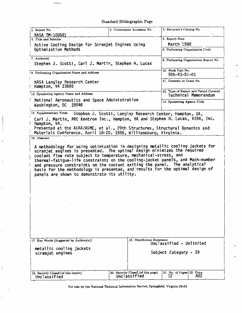
1. Report No. NASA TM- 100581
2. Government Accession No.
~~
r. Author(s) Stephen J. Sco t t i , Carl J. Mart in, Stephen H. Lucas
20. Security Classif.(of this page) Uncl ass i f i ed Unc 1 a s s i f i ed
19. Security Classif.(of this report)
~~~ ~
3, Performing Organization Name and Address
21. No. of Pages 22. Price 12 A02
NASA Langley Research Center Hampton, VA 23665
Nat ional Aeronautics and Space Admin is t ra t ion Washington, DC 20546
12. Sponsoring Agency Name and Address
3. Recipient’s Catalog No.
5. Report Date
March 1988 6. Performing Organization Code
8. Performing Organization Report No.
10. Work Unit No. 505- 43-81 -0 1
11. Contract or Grant No.
13. Type of Report and Period Covered Technical Memorandum
14. Sponsoring Agency Code
15. SupplementqNotes Stephen J . S c o t t i , Langley Research Center, Hampton, VA, Carl J . Mart in, PRC Kentron Inc., Hampton, VA and Stephen H. LUCaS, V IRA, Inc. Hampton, VA. Presented a t t he AIAA/ASME, e t a1 . , 29th Structures, S t ruc tu ra l Dynamics and Mater ia ls Conference, A p r i l 18-20, 1988, Williamsburg, V i rg in ia .
16. Abstract
A methodology f o r us ing op t im iza t ion i n designing m e t a l l i c coo l i ng jacke ts f o r scramjet engines i s presented. The optimal design minimizes the requ i red coolant f l ow r a t e subject t o temperature, mechanical -stress, and thermal - fa t igue-1 i f e cons t ra in ts on the cool ing- jacket panels, and Mach-number and pressure cons t ra in t s on the coolant e x i t i n g the panel. bas is f o r the methodology i s presented, and r e s u l t s f o r the optimal design o f panels are shown t o demonstrate i t s u t i l i t y .
The a n a l y t i c a l
17. Key Words (Suggested by Authors(s))
m e t a l l i c coo l i ng jacke ts scramjet engines
18. Distribution Statement Unc lass i f i ed - Un l im i ted
Subject Category - 39