Embed Size (px)
Citation preview
Twenty-Third Symposium (International) on Combustion/The Combustion Institute, 1990/pp. 1087-1092
ACTIVE CONTROL FOR GAS TURBINE COMBUSTORS
J. BROUWER, B. A. AULT, J. E. BOBROW AND G. S. SAMUELSEN UCI Combustion Laboratory
Institute of Combustion and Propulsion Science and Technology University of California
Irvine, CA 92717
Closed-loop feedback control is implemented in two model combustors as a demonstration of the application of feedback control to gas turbine combustion. The first combustor is an axi-symmetric, swirl-stabilized, spray-fired combustor, while the second combustor incorpo- rates discrete wall injection of primary and dilution air, representative of an actual gas tur- bine combustor. In both combustors, the emission of carbon monoxide and carbon dioxide, the radiative heat flux to the liner associated with soot and combustor stability are monitored in real time and controlled as a function of combustor load. The control input to the system is the nozzle atomizing air flow rate. The emission of carbon monoxide and carbon dioxide, the radiative flux to the liner, and the combustor stability are obtained through non-intrusive radiometric sensors mounted near the combustor exit plane. This information is conveyed to a control computer which invokes an optimization algorithm to minimize the CO and soot radiative flux, while maximizing the CO2 radiative flux. The index of combustion instability (onset of elevated acoustic emission) is, in the present case, a characteristic frequency in the power spectral density of the CO signal. The identical control methodology is applied to the two combustors with satisfactory and promising results that demonstrate the potential of ac- tive control to practical systems.
Introduction
As gas turbine combustors evolve to higher lev- els of performance, the development and applica- tion of active control techniques become increas- ingly important. One reason is the desire to achieve and maintain optimum performance over a wide range of operating conditions. A second reason is to identify off design conditions and counter with an appropriate response.
The present paper reports on the development and application of such a methodology. While ac- tive techniques are being developed and demon- strated for turbulent reacting flows of fundamental interest, 1'2 the present paper addresses the prac- tical application of active control to a gas turbine combustor. The current control methodology also differs from the fundamental studies in that the combustion process is modified on time scales that are large compared to flow times. The performance variables selected for control are combustion effi- ciency, radiative flux to the liner from soot, and combustor stability. While combustion efficiency is a measure of overall combustor performance, the radiative flux contributes directly to the thermal load of the combustor liner and, in excess, can result in premature failure of the liner. The radiative flux also serves as an indicator of soot emission and, as such,
is a measure of both environmental impact and, in combination with carbon monoxide, combustor inefficiency. Stability is essential to monitor and maintain as well. In the present case, combustor stability is that associated with large magnitude pressure oscillations which can lead to blowout.
The objective of the present study is to delineate a strategy for the application of active feedback con- trol technology to gas turbine type combustion in order to increase combustion efficiency, reduce the radiative flux to the liner, and maintain combustor stability independent of load setting. The utility of such a technique is two-fold. First, as the load of the combustor is changed, the combustor perfor- mance will be automatically adjusted and opti- mized. Second, an off-design condition (e.g., a clogged nozzle) can be detected and compensatory action can be initiated.
Approach
The approach consisted of five steps. The first was to adopt suitable sensors as indicators of com- bustion effciency, radiative flux, and combustor stability. The second was to select, for purposes of demonstration, a convenient combustor input pa- rameter that has an established influence on com-
1087
1088 ENGINES
bustor performance and is amenable to control. The third was to establish a control strategy that would transform measurements of the sensors into action by the combustor input parameter. The fourth step was to adopt combustor configurations, each with distinctly different aerodynamics, that would serve as a test of the control systems. The final step was to implement the control strategy.
To monitor combustor performance and provide a sensing array for the control system, radiometers were selected based on a series of developmental studies performed in the UCI Combustion Labo- ratory. 3'4 In the present case, three radiometers were designed to respond to and measure the radiative flux from CO, CO2, and soot.
For controlling the performance of the combus- tor, a number of options are available. The more attractive candidates encompass inlet flow and boundary conditions. Examples include the geom- etry of the inlet plane (see, for example, Reference 5), the swirler strength, the fuel injector, and/or the atomizing air. For the present study, the nozzle atomizing air flow rate (NAFR) was selected as con- trol input to the combustor since (1) the nozzle air flow is amenable to direct control, and (2) the per- formance of combustors has been found to be highly dependent on this parameter. 6'7
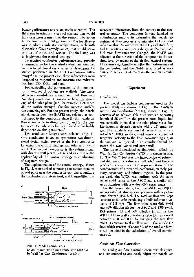
Two combustor designs were selected (Fig. 1). One combustor is an axi-symmetric two-dimen- sional design which served as the base combustor for which the control strategy was originally devel- oped. The second combustor is three-dimensional with discrete wall jets which served as a test of the applicability of the control strategy to combustors of disparate design.
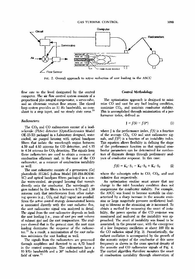
The implementation of the control strategy, shown in Fig. 2, consisted of mounting the radiometers on optical ports near the combustor exit plane, igniting the combustor at a given load, and transmitting the
' [ 32~ [ OILUTION AIA
57mm 19mm . ' ; ; : ' " ; ; ' ; . ..: 80rnm
I--x ~ - rws. ~LU~O .OZZLE
b )
Tw,. ..... .ozzLE~. l~-S~176176 "~ t _ _
w
PRIMARY JETS DILUTION JETS
FIC. 1. Mode] eombustors a) Axi-Symmetr ic Can Combustor (ASCC) b) Wall Jet Can Combustor (WJCC)
T 8Omm
3_
measured information from the sensors to the con- trol computer. The computer in turn invoked an optimization routine to determine the nozzle at- omizing air flow necessary to minimize CO and soot radiative flux, to maximize the CO2 radiative flux, and to maintain combustor stability. As the load (i.e., fuel mass flow rate) was changed, the NAFR was adjusted at the direction of the computer to the de- sired level by means of the air flow control system. The sensors continually monitor the performance of the combustor, and the NAFR is adjusted as nec- essary to achieve and maintain the optimal condi- tions.
Experiment
Combustors:
The model gas turbine combustors used in the present study are shown in Fig. 1. The Axi-Sym- metric Can Combustor (ASCC), shown in Fig. la, consists of an 80 mm OD duct with an operating length of 32 cm. s In the present case, liquid fuel was centrally injected at the inlet plane via a Par- ker Hannifin air-assist nozzle with a 45 ~ spray an- gle. The nozzle is surrounded concentrically by a set of 60 ~ , 100% solidity, swirl vanes which impart tangential velocity to the flow. Non-swirling air, or dilution air, is injected in an annular shroud be- tween the swirl vanes and outer wall.
The three-dimensional configuration, called the Wall Jet Can Combustor (WJCC), is shown in Fig. lb. The WJCC features the introduction of primary and dilution air via discrete wall jets, 9 and thereby produces a more accurate representation of the aerodynamics of a practical combustor; namely pri- mary, secondary, and dilution regions. In the pres- ent work, the WJCC was outfitted with the same set of swirl vanes as the ASCC and a similar air- assist atomizer with a wider (60 ~ spray angle.
For the current study, both the ASCC and WJCC are operated at atmospheric pressure with a petro- leum derived JP-4 fuel. The total air flow was kept constant at 80 scfm producing a bulk reference ve- locity of 7.5 m/s. The flow splits were 60% swirl and 40% dilution air for the ASCC and 45% swirl, 25% primary jet and 30% dilution jet air for the WJCC. The overall equivalence ratio (r was varied between 0.20 and 0.40 by changing the fuel flow rate at a constant total air flow rate. (The nozzle air flow, which consists of about 5% of the total air flow, is not included in the calculation of overall stoichi- ometry).
Nozzle Air Flow Controller:
An analog air flow control system was designed and constructed to accurately adjust the nozzle air
GAS TURBINE CONTROL
Computer
] 1 ~ Niolnolors
(
FIc. 2. Overall approach to active reduction of soot loading in the ASCC
1089
flow rate to the level designated by the control computer. The air flow control system consists of a proportional plus integral compensator, a servo-valve, and an electronic venturi flow sensor. The closed loop system provides an 11 Hz bandwidth, no over- shoot to a step input, and no steady state error, m
Radiometers:
The CO2 and CO radiometers consist of a lead- selenide (PbSe) detector (OptoElectronics Model OE-15-53) packaged in a Laboratory designed, water cooled, air purged housing with optical bandpass filters that isolate the wavelength region between 4.59 and 4.93 microns for CO detection, and 4.15 to 4.54 microns for CO2 detection. The signals from these radiometers are used to obtain a measure of combustion efficiency and, in the case of the CO radiometer, as a measure of combustion instability as well.
The soot radiometer consists of a germanium (Ge) photodiode (EG&G Judson Model J16-18A-RO1M- SC) and optical bandpass filters packaged in a sim- ilar water-cooled, air-purged housing that mounts directly onto the combustor. The wavelength re- gion isolated by the filters is between 0.75 and 1.30 microns such that interferences from other radiat- ing species (e.g., CO2 and H20 vapor) are avoided. Since the active control strategy demonstrated herein is associated directly with the soot radiative flux, the soot radiometer signal was analyzed in detail. The signal from the soot radiometer depends on both the soot loading (i.e., mass of soot per unit volume of exhaust gas) and the soot temperature. The anal- yses showed that in the present case, the soot mass loading dominates the response of the radiome- ter. H As a result, a minimization of the soot radia- tion minimizes the soot loading as well.
The signals from the radiometers are processed through amplifiers and directed to an A/D board in the control computer. The radiometers have a 10 kHz bandwidth and a 30 ~ included solid angle field of view. 11
Control Methodology
The optimization approach is designed to mini- mize CO and soot for any fuel loading condition, maximize CO2, and maintain combustor stability. This is accomplished through minimization of a per- formance index, defined as
J = f ( S ) - f ( I * ) (1)
where J is the performance index, f(S) is a function of the average CO2, CO and soot radiometer sig- nals, and f(I*) is a function of an instability index. This equation allows flexibility in defining the shape of the performance function so that optimal com- bustor parameters can be determined for combus- tors of disparate design through preliminary anal- yses of combustor response. In this case:
f(S) = KI" S1 - K2" $2 + K3" $3 (2)
where the subscripts refer to CO, CO2, and soot radiative flux respectively.
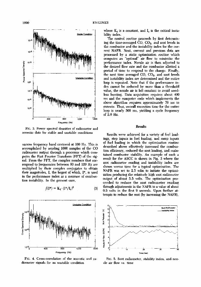
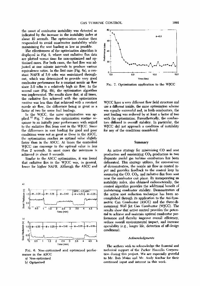
An optimization routine must assure that any change to the inlet boundary condition does not compromise the combustor stability. For example, the ASCC was found to become unstable (as char- acterized by a sharp increase in the acoustic emis- sion or large magnitude pressure oscillations) lead- ing to blowout as the atomizing air is increased. To obtain a method for measuring the onset of insta- bility, the power spectra of the CO emission was monitored and analyzed as the instability was ap- proached. The onset of instability was found to be associated, in the present case, with the emergence of a low frequency oscillation at about 100 Hz in the CO radiation signal (Fig. 3). Parenthetically, the radiant oscillation is accompanied by the growth of the acoustic output of the combustor at this same frequency as shown in the cross spectral density of the acoustic and CO radiometer signals of Fig. 4. The control algorithm therefore monitors the onset of combustion instability through observation of
1090 ENGINES
10-3
10-6
-~ 10"9
15
O. 100
10"3
10-6
lO'g
400 800 1200 1600
Frequency (Hz)
FIC. 3. Power spectral densities of radiometer and acoustic data for stable and unstable conditions
narrow frequency band centered at 100 Hz. This is accomplished by sending 1000 samples of the CO radiometer output through a processor which com- putes the Fast Fourier Transform (FFT) of the sig- nal. From the FFT, the complex numbers that cor- respond to frequencies between 80 and 120 Hz are multiplied by their complex conjugates to obtain their magnitudes, I, the largest of which, I*, is used in the performance index as a measure of combus- tion instability. In the present ease,
f(I*) : 1(4. (I*/I~) 2 (3)
where 1(4 is a constant, and Ic is the critical insta- bility index.
The control routine proceeds by first determin- ing the time-averaged CO, CO2, and soot levels in the combustor and the instability index for the cur- rent NAFR. Next, current and previous data are processed by a static optimization routine which computes an "optimal" air flow to minimize the performance index. Nozzle air is then adjusted to the desired flow rate and the combustor allotted a period of time to respond to the change. Finally, the next time averaged CO, CO~, and soot levels and instability index are determined and the entire loop is repeated. Note that if the performance in- dex cannot be reduced by more than a threshold value, the nozzle air is left constant to avoid need- less hunting. Data acquisition requires about 400 ms and the computer code which implements the above algorithm requires approximately 70 ms to execute. Thus, overall execution time for the entire loop is nearly 500 ms, yielding a cycle frequency of 2.0 Hz.
Results
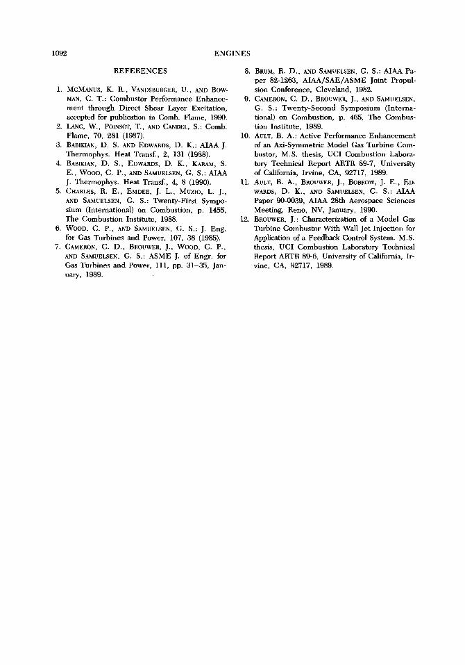
Results were achieved for a variety of fuel load- ings, step inputs in fuel loading, and ramp inputs of fuel loading in which the optimization routine described above effectively increased the combus- tion efficiency, reduced the soot loading, and main- tained combustor stability. An example of such a result for the ASCC is shown in Fig. 5 where the soot radiometer reading and instability index are shown versus time for a typical optimization. The NAFR was set to 2.5 scfm to initiate the optimi- zation producing the relatively high soot radiometer output of about 5.5 volts. The optimization pro- ceeded to reduce the soot radiometer reading through adjustments in the NAFR to a value of about 0.5 volts in the first 9 seconds. Upon further at- tempts to reduce the soot (by increasing the NAFR),
10 -3
10~i 2 o
U n ~ a b l e C o n d ~ n
' " 0 400 800 1200 1600
Frequency (Hz)
FIC. 4. Cross-correlation of the acoustic and ra- diometer signals for an unstable condition
6
. . . . Ip.$tabilily Index
"nrr~ ( sac )
FIc. 5. Soot radiometer, stability index, and noz- zle air flow vs. time
GAS TURBINE CONTROL 1091
the onset of combustor instability was detected as indicated by the increase in the instability index at about 10 seconds. The optimization routine then responded to avoid eombustor instability while maintaining the soot loading as low as possible.
The effectiveness of the optimization algorithm is displayed in Fig. 6, where soot radiative flux data are plotted versus time for non-optimized and op- timized cases. For both cases, the fuel flow was ad- justed at one minute intervals to produce various equivalence ratios. In the first case (Fig. 6a), a con- stant NAFR of 5.0 scfm was maintained through- out, which was determined to provide very good combustor performance for a constant nozzle air flow since 5.0 scfm is a relatively high air flow. In the second case (Fig. 6b), the optimization algorithm was implemented. The results show that, at all times, the radiative flux achieved with the optimization routine was less than that achieved with a constant nozzle air flow, the difference being as great as a factor of two for some fuel loadings.
In the WJCC, the same optimization was ap- plied. 12 Fig. 7 shows the optimization routine re- sponse to an initially poor performance with regard to the radiative flux from soot in the WJCC. Since the differences in soot loading for good and poor conditions were not as great as those in the ASCC, the optimization reaches an optimal value slightly faster than in the ASCC. At times the controlled WJCC can converge to the optimal value in less than 2 seconds. In most cases the minimum is achieved in about 6 seconds.
Similar to the ASCC optimization, it was found that radiative flux in the WJCC was, in general, lower for higher NAFR. Although the ASCC and
a)
o 21-- / / ' I NFR = 5.0 scfm "
1 . 5 ~ - ~ = 0 .30 + * = 0.25 + ~ = 0 .40 ~ , - ~ = 0 . 2 5 4 - ~ = 0 . 3 5 .
~ 0.5
m 0 0.5 1 1.5 2 2.5 3 3.5 4 4.5 5
Time (min)
b)
1. = 0 .30 ~ = 0.25 ~ = 0 .40 ~ = 0.25 ~ = 0.35~
~ ~0 0.5 1 1.5 2 2 .5 3 3 .5 4 4 .5
T i m e (m in )
FIC. 6. Non-optimized and optimized perfor- mance in the ASCC
a) Non-optimized b) Optimized
80
60
~40
0. 20
e, e ~ =0.3
\
x,
" - . - ~ - - - - ~ / ' \ / \ .-- A
0 i r t i I i ~ t , I i , ~ i 0.0 5.0 10.0 15.0
~ m e (See)
FIG. 7. Optimization application to the WJCC
WJCC have a very different flow field structure and use a different nozzle, the same optimization scheme was equally successful and, in both combustors, the soot loading was reduced by at least a factor of two with the optimization. Parenthetically, the combus- tors differed in overall stability. In particular, the WJCC did not approach a condition of instability for any of the conditions considered.
Summary
An active strategy for minimizing CO and soot production and maximizing CO2 production in two disparate model gas turbine combustors has been delineated. This strategy utilizes, for convenience of demonstration, the nozzle air flow as control in- put and provides feedback to the control loop by measuring the CO, CO2, and radiative flux from soot near the combustor exit plane. By incorporating an instability index, also obtained radiometrically, the control algorithm provides the additional benefit of maintaining combustor stability. Demonstration of the active soot reduction technique has been ac- complished through its application to the Axi-Sym- metric Can Combustor (ASCC) and the three-di- mensional Wall Jet Can Combustor (WJCC). The results show that active control provides the poten- tial to achieve and maintain optimal combustor per- formance and thereby improve overall efficiency, reduce overall environmental impact, and increase operability (e.g., longer life, detection of off-design conditions).
Acknowledgments
The authors wish to acknowledge the financial and technical support of the Parker Hannifin Corpora- tion during this project. We are especially grateful to Mr. Bob Mains and Mr. Andy Kuchar for their continued input and interest in this work.
1092 ENGINES
REFERENCES
1. MCMANuS, K. R., VANDSBURGER, U., AND BOW- MAN, C. T. : Combustor Performance Enhance- ment through Direct Shear Layer Excitation, accepted for publication in Comb. Flame, 1990.
2. LaNG, W., POINSOr, T., AND C~DEL, S.: Comb. Flame, 70, 281 (1987).
3. BAm~IAN, D. S. AND EDWARDS, D. K.: AIAA J. Thermophys. Heat Transf., 2, 131 (1988).
4. BABIKIAN, D. S., EDWARDS, D. K., KARAM, S. E., WOOD, C. P., AND SAMUELSEN, G. S.: AIAA J. Thermophys. Heat Transl., 4, 8 (1990).
5. CHARLES, R. E., EMDEE, J. L., M~zIo, L. J., AND SAMUELSEN, G. S.: Twenty-First Sympo- sium (International) on Combustion, p. 1455, The Combustion Institute, 1988.
6. WOOD, C. P., AND SAMUELSEN, G. S.: J. Eng. for Gas Turbines and Power, 107, 38 (1985).
7. CAMERON, C. D., BROOWER, J., WooD, C. P., AND SAMUELSEN, G. S.: ASME J. of Engr. for Gas Turbines and Power, 111, pp. 31-35, Jan- uary, 1989.
8. BRUM, R. D., AND SAMUELSEN, G. S.: AIAA Pa- per 82-1263, AIAA/SAE/ASME Joint Propul- sion Conference, Cleveland, 1982.
9. CAMERON, C. D., BROUWER, J., AND SAMUELSEN, G. S.: Twenty-Second Symposium (Interna- tional) on Combustion, p. 465, The Combus- tion Institute, 1989.
10. AtJLT, B. A.: Active Performance Enhancement of an Axi-Symmetric Model Gas Turbine Com- bustor, M.S. thesis, UCI Combustion Labora- tory Technical Report ARTR 89-7, University of California, Irvine, CA, 92717, 1989.
11. AULT, B. A., BRO~WER, J., BORROW, J. E., ED- WARDS, D. K., AND SAMUELSEN, G. S.: AIAA Paper 90-0039, AIAA 28th Aerospace Sciences Meeting, RenD, NV, January, 1990.
12. BROUWER, J. : Characterization of a Model Gas Turbine Combustor With Wall Jet Injection for Application of a Feedback Control System. M.S. thesis, UCI Combustion Laboratory Technical Report ARTR 89-6, University of California, Ir- vine, CA, 92717, 1989.