Embed Size (px)
Citation preview
AC 3Active Antenna Combiner
Instruction manual

AC 3 | 1
Contents
Contents
Important safety instructions ........................................................ 2
The AC 3 active transmitter combiner ......................................... 4
Delivery includes ............................................................................... 4
Operating controls ............................................................................ 5
Block diagram .................................................................................... 6
Putting the AC 3 into operation .................................................... 7Preparing the AC 3 for use ............................................................ 7
Using the AC 3 ................................................................................. 12
Cleaning the AC 3 ........................................................................... 13
If a problem occurs ... ..................................................................... 14
Accessories ...................................................................................... 15
Specifications .................................................................................. 16
Manufacturer Declarations ........................................................... 17
2 | AC 3
Important safety instructions
Important safety instructions
• Read this instruction manual.
• Keep this instruction manual. Always include this instruction
manual when passing the device on to third parties.
• Heed all warnings and follow all instructions in this instruc-
tion manual.
• Clean only with a slightly damp cloth.
• Refer all servicing to qualified service personnel.
Servicing is required if the device has been damaged in any
way, liquid has been spilled, objects have fallen inside, the
device has been exposed to rain or moisture, does not operate
properly or has been dropped.
• WARNING: To reduce the risk of fire or electric shock, do not
use the device near water and do not expose it to rain or mois-
ture. Do not place objects filled with liquids, such as vases or
coffee cups, on the device.
• Only use the NT 3-1 table top power supply (see “Accesso-
ries” on page 15).
• Do not block any ventilation openings. Install the device in
accordance with the instructions given in this manual.
• Do not install the device near any heat sources.
• Only use attachments/accessories specified by Sennheiser.
Replacement parts
When replacement parts are required, be sure the service
technician uses replacement parts specified by Sennheiser or
those having the same characteristics as the original part.
Unauthorized substitutions may result in fire, electric shock, or
other hazards.
Safety check
Upon completion of any service or repairs to this device, ask the
service technician to perform safety checks to determine that
the device is in a safe operating condition.
AC 3 | 3
Important safety instructions
Intended use of the device
Intended use of the AC 3 includes:
• having read and understood this instruction manual especi-
ally the chapter “Important safety instructions” on page 2,
• using the device within the operating conditions and limita-
tions described in this instruction manual.
“Improper use” means using the AC 3 other than as described
in this instruction manual, or under operating conditions which
differ from those described herein.
4 | AC 3
The AC 3 active transmitter combiner
The AC 3 active transmitter
combiner
With the AC 3 4-to-1 active transmitter combiner, the signals of
up to four SR 300 IEM G3 type transmitters can be combined
onto a single antenna.
The AC 3-US version is a special design approved for the U.S./
Canada and is intended as a combiner for he SR 300 IEM G3 A1.
The integral active RF amplifiers ensure that the input signals
are combined onto the common antenna output with no distri-
bution attenuation.
The AC 3 incorporates DC distribution to enable simultaneous
powering of up to four transmitters via its BNC sockets. A single
NT 3-1 table top power supply (see “Accessories” on page 15)
is required to power the AC 3 and the connected transmitters.
Using the GA 3 rack adapter (see “Accessories” on page 15),
one AC 3 and one stationary SR 300 IEM G3 type transmitter
can be mounted into a 19” rack.
Alternatively, you can stack the AC 3. For stacking the AC 3,
mount the optional stacking elements (see “Accessories” on
page 15).
The AC 3 is suitable for the following areas of application:
• Multi-channel monitoring systems for stage use
• Multi-channel systems suitable for any application where
talk-back signals are to be transmitted (e.g. studio)
Delivery includes
1 AC 3 or AC 3-US active transmitter combiner
1 set of device feet
4 BNC cables
1 instruction manual
You additionally require the NT 3-1 table top power supply with
a suitable mains connector (see “Accessories” on page 15).
AC 3 | 5
Operating controls
Operating controls
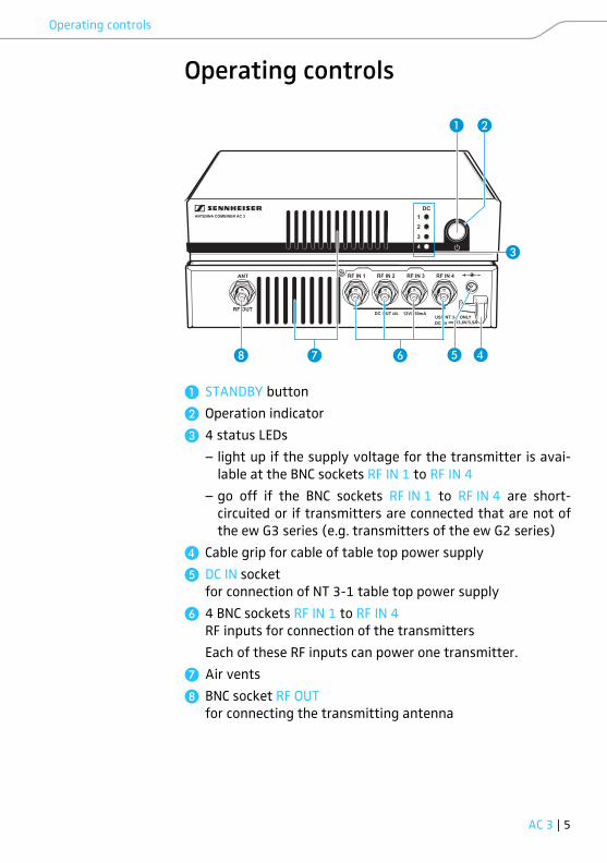
� STANDBY button
� Operation indicator
� 4 status LEDs
– light up if the supply voltage for the transmitter is avai-
lable at the BNC sockets RF IN 1 to RF IN 4
– go off if the BNC sockets RF IN 1 to RF IN 4 are short-
circuited or if transmitters are connected that are not of
the ew G3 series (e.g. transmitters of the ew G2 series)
� Cable grip for cable of table top power supply
� DC IN socket
for connection of NT 3-1 table top power supply
� 4 BNC sockets RF IN 1 to RF IN 4
RF inputs for connection of the transmitters
Each of these RF inputs can power one transmitter.
� Air vents
BNC socket RF OUT
for connecting the transmitting antenna
ANT
RF OUT
RF IN 1 RF IN 2 RF IN 3 RF IN 4
USE NT 3-1 ONLYDC IN 13,8V/3,5A
12V/350mADC OUT
DC1234
ANTENNA COMBINER AC 3
� �
� � ��
�
6 | AC 3
Block diagram
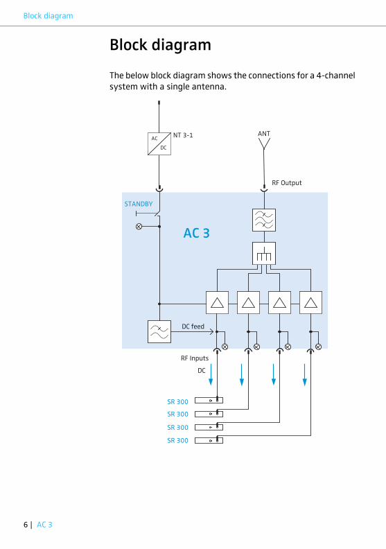
Block diagram
The below block diagram shows the connections for a 4-channel
system with a single antenna.
AC
DC
NT 3-1 ANT
AC 3
SR 300
RF Output
DC
RF Inputs
SR 300
SR 300
SR 300
STANDBY
DC feed

AC 3 | 7
Putting the AC 3 into operation
Putting the AC 3 into operation
Preparing the AC 3 for use
Setting up the AC 3 on a flat surface
� Place the AC 3 on a flat, horizontal surface.
Fastening the
stacking elements
To fasten the stacking elements :
� Unscrew and remove the two recessed head screws (M4x8)
on each side of the AC 3.
� Secure the stacking elements to the sides of the AC 3
using the previously removed recessed head screws (see
diagram).
The stacking elements (see “Accessories” on page 15)
are designed to help protect the operating elements
from damage or deformation, e.g. if the AC 3 is
dropped.
� Fasten the stacking elements even if you do not
want to stack your AC 3.
� Do not fasten the stacking elements when mounting
the AC 3 into a 19” rack (see page 9).
8 | AC 3
Putting the AC 3 into operation
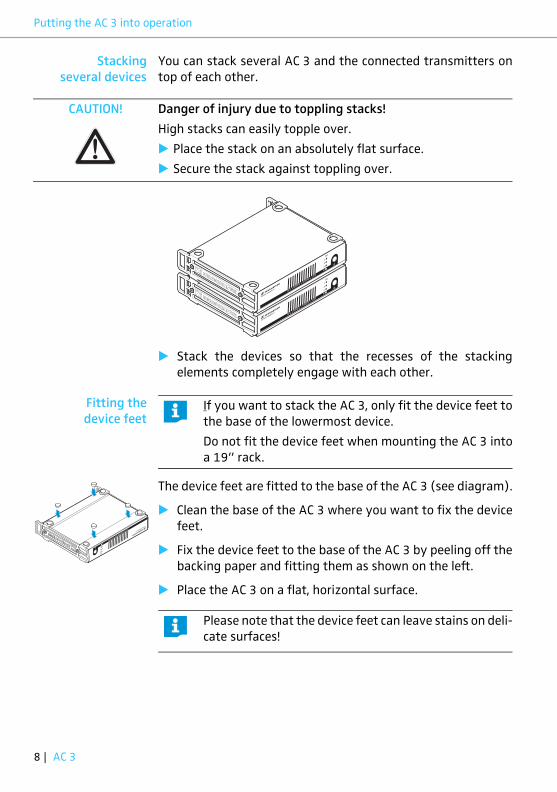
Stacking
several devices
You can stack several AC 3 and the connected transmitters on
top of each other.
.
� Stack the devices so that the recesses of the stacking
elements completely engage with each other.
Fitting the
device feet
The device feet are fitted to the base of the AC 3 (see diagram).
� Clean the base of the AC 3 where you want to fix the device
feet.
� Fix the device feet to the base of the AC 3 by peeling off the
backing paper and fitting them as shown on the left.
� Place the AC 3 on a flat, horizontal surface.
CAUTION! Danger of injury due to toppling stacks!
High stacks can easily topple over.
� Place the stack on an absolutely flat surface.
� Secure the stack against toppling over.
If you want to stack the AC 3, only fit the device feet to
the base of the lowermost device.
Do not fit the device feet when mounting the AC 3 into
a 19” rack.
Please note that the device feet can leave stains on deli-
cate surfaces!
AC 3 | 9
Putting the AC 3 into operation
Mounting the AC 3 into a 19” rack
Rack mounting
one AC 3
� Secure the rack mount “ears” � (supplied with the optional
GA 3 rack adapter) to the AC 3 in the same way as described
for the stacking elements (see page 7).
� Secure the blanking plate � to one of the rack mount
“ears” � using two recessed head screws (M 6x10)
(see diagram on page 10).
� Insert the two blanking plugs into the holes of the blan-
king plate (see diagram on page 10).
CAUTION! Risks when rack mounting the device!
When installing the device in a closed or multi-rack assembly,
please consider that, during operation, the ambient tempera-
ture, the mechanical loading and the electrical potentials will be
different from those of devices which are not mounted into a
rack.
� The ambient temperature within the rack must not exceed
the temperature limit specified in the specifications.
� Ensure sufficient ventilation; if necessary, provide additional
ventilation.
� Make sure that the mechanical loading of the rack is even.
� When connecting to the power supply, observe the informa-
tion indicated on the NT 3-1 table top power supply. Avoid
circuit overloading. If necessary, provide overcurrent protec-
tion.
� When rack mounting, please note that intrinsically harmless
leakage currents of the individual power supplies may accu-
mulate, thereby exceeding the allowable limit value. As a
remedy, ground the rack via an additional ground connec-
tion.
10 | AC 3
Putting the AC 3 into operation
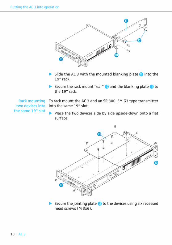
� Slide the AC 3 with the mounted blanking plate � into the
19” rack.
� Secure the rack mount “ear” � and the blanking plate � to
the 19” rack.
Rack mounting
two devices into
the same 19” slot
To rack mount the AC 3 and an SR 300 IEM G3 type transmitter
into the same 19” slot:
� Place the two devices side by side upside-down onto a flat
surface:
� Secure the jointing plate � to the devices using six recessed
head screws (M 3x6).
��
�
�
�
�
AC 3 | 11
Putting the AC 3 into operation
� Secure the rack mount “ears” � (supplied with the optional
GA 3 rack adapter) to the devices as described in the section
“Fastening the stacking elements” on page 7.
� Slide the devices into the 19” rack.
� Secure the rack mount “ears” to the 19” rack.
Connecting devices to the AC 3
Connecting
the antenna
We recommend connecting a remote antenna and, if necessary,
using Sennheiser antenna accessories (see “Accessories” on
page 15). For more information, refer to the ew G3 product
page at www.sennheiser.com.
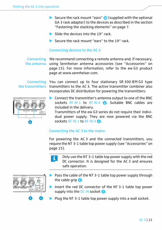
Connecting
the transmitters
You can connect up to four stationary SR 300 IEM G3 type
transmitters to the AC 3. The active transmitter combiner also
incorporates DC distribution for powering the transmitters:
� Connect the transmitter’s antenna output to one of the BNC
sockets RF IN 1 to RF IN 4 �. Suitable BNC cables are
included in the delivery.
Transmitters of the ew G3 series do not require their indivi-
dual power supply. They are now powered via the BNC
sockets RF IN 1 to RF IN 4 �.
Connecting the AC 3 to the mains
For powering the AC 3 and the connected transmitters, you
require the NT 3-1 table top power supply (see “Accessories” on
page 15).
� Pass the cable of the NT 3-1 table top power supply through
the cable grip �.
� Insert the red DC connector of the NT 3-1 table top power
supply into the DC IN socket �.
� Plug the NT 3-1 table top power supply into a wall socket.
RF IN 1 RF IN 2 RF IN 3 RF IN 4
USE NT 3-1 ODC IN 13
12V/350mADC OUT
�
Only use the NT 3-1 table top power supply with the red
DC connector. It is designed for the AC 3 and ensures
safe operation.
RF IN 2 RF IN 3 RF IN 4
USE NT 3-1 ONLYDC IN 13,8V/3,5A
12V/350mADC OUT
��

12 | AC 3
Using the AC 3
Using the AC 3
Switching the AC 3 on
.
� Briefly press the STANDBY button �.
The operation indicator � lights up green. The LEDs 1 ... 4 �behave as follows:
The RF signals of the correctly connected transmitters are
combined and transmitted via the connected transmitting
antenna.
CAUTION! Risk of fire due to overheating of the AC 3!
The AC 3 equipped with a fan to assist dissipation of generated
heat.
� Make sure that the air vents � of the AC 3 are not covered
or blocked.
The fan of the AC 3 is temperature-controlled and
operates only when required.
DC1234
�
�
�
LED 1 ... 4 � Meaning
lights up You have correctly connected an
SR 300 IEM G3 type transmitter;
the supply voltage for the trans-
mitter is available at BNC socket
RF IN 1 ... RF IN 4.
does not light up There is a short-circuit in the BNC
socket RF IN 1 ... RF IN 4:
� Read the chapter “If a problem
occurs ...” on page 14.
You have connected a transmitter
that is not of the ew G3 series:
� Make sure that this transmitter
has its own power supply.
AC 3 | 13
Cleaning the AC 3
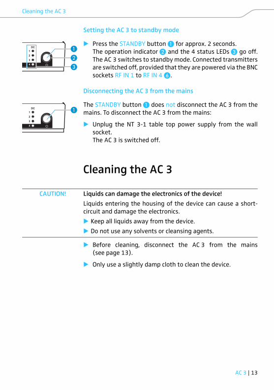
Setting the AC 3 to standby mode
� Press the STANDBY button � for approx. 2 seconds.
The operation indicator � and the 4 status LEDs � go off.
The AC 3 switches to standby mode. Connected transmitters
are switched off, provided that they are powered via the BNC
sockets RF IN 1 to RF IN 4 �.
Disconnecting the AC 3 from the mains
The STANDBY button � does not disconnect the AC 3 from the
mains. To disconnect the AC 3 from the mains:
� Unplug the NT 3-1 table top power supply from the wall
socket.
The AC 3 is switched off.
Cleaning the AC 3
� Before cleaning, disconnect the AC 3 from the mains
(see page 13).
� Only use a slightly damp cloth to clean the device.
DC1234
�
�
�
DC1234
�
CAUTION! Liquids can damage the electronics of the device!
Liquids entering the housing of the device can cause a short-
circuit and damage the electronics.
� Keep all liquids away from the device.
� Do not use any solvents or cleansing agents.

14 | AC 3
If a problem occurs ...
If a problem occurs ...
If a problem occurs that is not listed in the above table or if the
problem cannot be solved with the proposed solutions, please
contact your local Sennheiser partner for assistance.
Problem Possible cause Possible solution
Transmitters
cannot be
switched on
Transmitters are
not powered
Check the connections of
the NT 3-1 table top power
supply and/or check the
BNC sockets RF IN 1 to
RF IN 4 �
You have
connected trans-
mitters of the
ew G2 series
Make sure that these trans-
mitters have their own
power supply
Disturbed RF
transmission
Antenna is not
connected
correctly
Check the antenna
connection
Connection cable
is defective
Replace the connection
cable
Excessive RF
signal attenua-
tion due to too
long antenna
cable or incorrect
type of antenna
cable
Only use the recommended
antenna cable (see “Acces-
sories” on page 15)
or use a shorter antenna
cable
or use a low-attenuation
RF cable
LED 1 ... 4 �
does not light
up
Short-circuit in
the BNC socket
RF IN 1 ... RF IN 4
Check the antenna
connection
Replace the connection
cable
You have
connected trans-
mitters of the
ew G2 series
Make sure that these trans-
mitters have their own
power supply
AC 3 | 15
Accessories
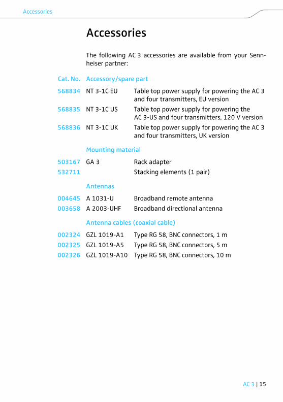
Accessories
The following AC 3 accessories are available from your Senn-
heiser partner:
Cat. No. Accessory/spare part
568834 NT 3-1C EU Table top power supply for powering the AC 3
and four transmitters, EU version
568835 NT 3-1C US Table top power supply for powering the
AC 3-US and four transmitters, 120 V version
568836 NT 3-1C UK Table top power supply for powering the AC 3
and four transmitters, UK version
Mounting material
503167 GA 3 Rack adapter
532711 Stacking elements (1 pair)
Antennas
004645 A 1031-U Broadband remote antenna
003658 A 2003-UHF Broadband directional antenna
Antenna cables (coaxial cable)
002324 GZL 1019-A1 Type RG 58, BNC connectors, 1 m
002325 GZL 1019-A5 Type RG 58, BNC connectors, 5 m
002326 GZL 1019-A10 Type RG 58, BNC connectors, 10 m

16 | AC 3
Specifications
Specifications
In complicance with
Approved by
Frequency range AC 3: 500 to 870 MHz
AC 3-US: 470 to 698 MHz
Distribution attenuation 0 dB (±1 dB)
RF input power max. 30 mW per input
Impedance 50 ΩSupply voltage 13.8 V DC
(with NT 3-1 table top power
supply)
Total current consumption max. 3.4 A
(with connected transmitters)
Supply voltage for trans-
mitters at RF IN 1 to
RF IN 4
11.4 V (protected from reverse
feed), 350 mA
Relative humidity 5 to 95%
Operating temperature range –10°C to +55°C
Storage temperature range –20°C to +70°C
Dimensions of housing approx. 212 x 168 x 43 mm
Weight approx. 1470 g
Europe EMC EN 301489-1/-9
Radio EN 300422-1/-2
Safety EN 60065
Canada Industry Canada RSS 210,
IC: 2099A-AC3,
limited to 698 MHz
USA CAN ICES-3(B)/NMB-3(B)
47 CFR Part 74
FCC-ID: DMOAC3,
limited to 698 MHz
AC 3 | 17
Manufacturer Declarations
Manufacturer Declarations
Warranty
Sennheiser electronic GmbH & Co. KG gives a warranty of
24 months on this product.
For the current warranty conditions, please visit our web site at
www.sennheiser.com or contact your Sennheiser partner.
In compliance with the following requirements
• WEEE Directive (2012/19/EU)
Please dispose of the AC 3 at the end of its operational
lifetime by taking it to your local collection point or recy-
cling center for such equipment.
CE Declaration of Conformity
•
• RoHS Directive (2011/65/EU)
• R&TTE Directive (1999/5/EG)
The declaration is available at
www.sennheiser.com/download. Before putting the device
into operation, please observe the respective country-specific
regulations.
Australia
18 | AC 3
Manufacturer Declarations
FCC & Industry Canada Information
This device complies with Part 15 of the FCC Rules. Operation is
subject to the following two conditions:
(1) This device may not cause harmful interference, and
(2) this device must accept any interference received, including
interference that may cause undesired operation.
This class B digital device complies with the Canadian ICES-003.
Changes or modifications made to this equipment not expressly
approved by Sennheiser electronic Corp. may void the FCC
authorization to operate this equipment. Before putting the
device into operation, please observe the respective country-
specific regulations!
Radiofrequency radiation exposure information:
This equipment complies with FCC and IC radiation exposure
limits set forth for an uncontrolled environment. The AC 3
should be installed and operated with a minimum distance of
20 cm between the radiator and your body.


Sennheiser electronic GmbH & Co. KG
Am Labor 1, 30900 Wedemark, Germanywww.sennheiser.comPubl. 10/16, 532863/A03