Embed Size (px)
Citation preview
August 30, 2008 13:56 IJHR08
International Journal of Humanoid Roboticsc© World Scientific Publishing Company
ACTIVE 3D VISION IN A HUMANOID ROBOT
FABRIZIO SANTINI
Department of Cognitive and Neural Systems, Boston University, 677 Beacon StreetBoston, MA 02215, United States of America
ROHIT NAMBISAN
Department of Cognitive and Neural Systems, 677 Beacon StreetBoston, MA 02215, United States of America
MICHELE RUCCI
Departments of Psychology, Biomedical Engineering, and Program in Neuroscience,677 Beacon Street, Boston, MA 02215, United States of America
Received 30 August 2008
Motion parallax, the relative motion of 3D space at different distances experienced bya moving agent, is one of the most informative cues. While motion parallax is typicallyinvestigated during navigation, it also occurs in most robotic head/eye systems duringrotations of the cameras. In these systems, as in the eyes of many species, the optical
nodal points do not lie on the axes of rotation. Thus, a camera rotation shifts an object’sprojection on the sensor by an amount that depends not only on the rotation amplitude,but also on the distance of the object with respect to the camera. Several species rely onthis cue to estimate distance. An oculomotor parallax is present also in the human eye,and during normal eye movements, displaces the stimulus on the retina by an amountthat is well within the range of sensitivity of the visual system. We developed an anthro-pomorphic robot equipped with an oculomotor system specifically designed to reproducethe images impinging on the human retina. In this study, we thoroughly characterize theoculomotor parallax emerging while replicating human eye movements with this robotand describe a method for combining 3D information resulting from pan and tilt rota-tions of the cameras. We show that emulation of the dynamic strategy by which humansscan a visual scene gives accurate estimation of distance within the space surroundingthe robot.
Keywords: Biomorphic Robotics; Embedded Systems; Eye Movements; ComputationalNeuroscience; Stereopsis; Head/eye system; Depth from Motion.
1. Introduction
The establishment of accurate spatial representations is one of the primary tasks
faced by robots operating in unconstrained environments. Reliable spatial repre-
sentations are necessary not only to store information about the three-dimensional
1
August 30, 2008 13:56 IJHR08
2 Fabrizio Santini, Rohit Nambisan, and Michele Rucci
structure of the scene, i.e., the spatial arrangement of objects relative to one other,
but also to provide ready access to information regarding the distance of objects and
surfaces with respect to the agent. This egocentric distance information is critical
in all operations that involve interaction with the environment, such as navigation
and manipulation.
Within different ranges of distance, several sensory modalities convey valuable
3D information. Some modalities, such as touch, can be used only within a space
in close proximity to the agent; others, such as audition, tend to be useful at larger
distances. However, in most modalities, access to 3D information does not come
effortlessly. In fact, depth/distance information is typically not explicitly available
in input sensory representations, but is implicitly stored in a variety of sensory cues.
A nonexplicit representation of 3D information also occurs in vision, the pri-
mary source of judgement for egocentric distance in primates and many mammals.
Depth/distance information is lost in the projection of a three-dimensional scene
onto the two dimensional surface of a visual sensor. However, a variety of visual
cues, both monocular and binocular, incorporate information about the 3D struc-
ture of the scene over an extraordinarily large range of distances 1. Most of these
cues have been used by robotic vision systems. Methods for implementing 3D vision
in robotics range from the comparison of images taken from different points of view
(stereoscopic vision)2;3, to consideration about prior knowledge of the scene and
the physical process of image formation4–7.
In a moving agent, an important 3D cue is given by the motion parallax, i.e.,
the different apparent motion of stationary objects at different distances 8–10. Mo-
tion parallax is most evident for large movements of the agent, as when the agent
navigates through the scene. A number of studies have examined the parallax that
emerges by mounting a vision system on a mobile platform11–17. These large move-
ments of the camera amplify the motion parallax. However, if the nodal points of
the optical system do not lie on the axes of rotations, camera rotations of a sta-
tionary head/eye system will also produce a parallax. Since such a misalignment
of the cardinal points always occurs, unless it is intentionally eliminated by careful
specification of the system’s optical and mechanical characteristics, an oculomotor
parallax is present in virtually every pan/tilt unit used in robotics.
A similar parallax occurs in the eyes of many species, as the optical nodal points
of the lens and cornea are not coincident with the center of rotation of the eye. Thus,
during a relocation of gaze, the projection of an object on the retina moves by an
amount that depends both on the amplitude of the rotation and on the distance of
the object from the observer (see Fig. 1). Species as diverse as the chameleon and
the sandlance, for which the optics of the eye maximize the distance between nodal
points and the center of rotation, heavily rely on this cue to judge distance 18;19. An
oculomotor parallax is also present in the eyes of primates and, during the normal
scanning of a visual scene, produces retinal shifts that are well within the range of
visual acuity20–22.
This study investigates the use of the oculomotor parallax in the visual estima-
August 30, 2008 13:56 IJHR08
Active 3D Vision in a Humanoid Robot 3
tion of egocentric distance in a humanoid robot. Since the 3D information provided
by this cue depends on the precise movements of the sensor that produce it, we focus
on the oculomotor activity of human observers. Under natural viewing conditions,
humans tend to redirect their gaze by means of small movements 23. These saccades
appear to be ideal for using the oculomotor parallax, as they are sufficiently large
to provide reliable distance information, yet small enough to cause minimal dis-
tortion in the retinal image. The results presented in this paper builds upon our
previous work on replicating the strategy by which humans scan a visual scene in a
robot24;25. In these previous studies, only redirections of gaze along the azimuthal
axis were used to extract 3D information. In this article, we report the results of
more recent experiments in which we used a new and improved head/eye system to
replicate saccades in all directions. We describe a method for combining the hori-
zontal and vertical components of the parallax present with saccades in arbitrary
directions. Furthermore, we examine the impact of motor and visual errors, and
introduce a compensation for the effect of target eccentricity on the evaluation of
the parallax and distance estimation. We show that the oculomotor parallax that
emerges during normal eye movements in humans provides highly accurate spatial
information within a range of nearby distances.
This paper is organized as follows: In section 2, we review the geometry of
the oculomotor parallax and describe an approach to the estimation of distance
based on rotations of the sensor. Section 3 describes the pan/tilt unit used in this
study, its optical and mechanical properties, and the calibration process followed to
precisely position the cardinal points. This system constitutes the oculomotor unit
of the APLab humanoid robot, an anthropomorphic platform for interdisciplinary
research on sensory perception and motor control. The results of both computer
simulations and robotic experiments in which the robot moved following recorded
sequences of human eye movements are reported in section 4. We conclude with a
brief discussion of our experimental results and possible extensions of the proposed
approach.
2. Distance Estimation Based on the Oculomotor Parallax
The recovery of the distance of an object from its projection on a 2D image is an
inherently ambiguous problem. Since one of the spatial dimensions is lost in the
process of image formation, any given image could result from objects at infinitely
many locations. This study describes an active approach for extracting distance
information, which relies on the apparent motion of objects caused by camera ro-
tations. For simplicity, in this section, we consider the ideal case of a Point Light
Source (PLS), an infinitesimally small light source that projects onto a single point
on the camera’s sensor.
Fig. 2 provides an intuitive explanation of the method by considering the case
of a single rotation around the pan axis. In this example, two PLSs, are located at
positions A and B, which differ in their distances (dA and dB) and eccentricities
August 30, 2008 13:56 IJHR08
4 Fabrizio Santini, Rohit Nambisan, and Michele Rucci
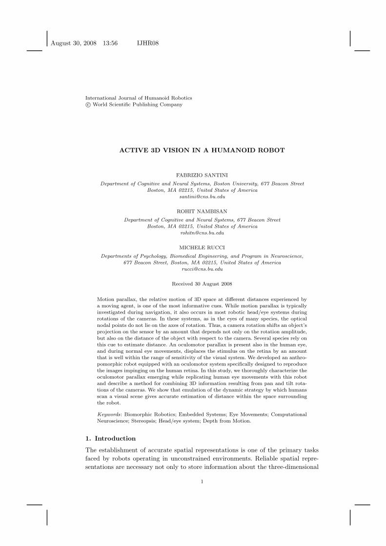
Figure 1. The oculomotor parallax. (Top Row) In the eyes of humans and other species, the opticalnodal points, N1 and N2, are displaced with respect to the center of rotation C. Because of thisoffset, a rotation of the eye moves the projection of an object on the retina by an amount thatdepends not only on the rotation amplitude but also on the distance of the object. The two panelsillustrate the projections of two objects, A and B, before and after a rotation θ. The two objects
project on the same retinal location before the rotation and on two separate retinal points afterthe rotation. The numbers on the left panel represent the mean distances between nodal points,center of rotation, and the surface of retinal receptors in Gullstrand’s model of the human eye 26 .(Bottom Row) An example of distance information given by the oculomotor parallax. The twoimages were acquired by the head/eye system described in this paper before and after a rotationof 7◦. This robot accurately replicates the oculomotor parallax present in the human eye. Notethe portion of the horse occluded by the bishop in the image acquired before the movement (left),which becomes visible following the camera’s rotation (right).
(αA and αB) with respect to the agent. The agent, however, sees only one target:
since A and B lie on the same line H going through the lens’ nodal point N1, the
two PLSs project on the same exact point uAB on the camera’s sensor. Indeed, A
and B are just two instances of the infinite number of combinations of distance
and eccentricity (d, α), yielding the same projection on the sensor (the curve H in
Fig. 2(b))
A rotation of the camera provides an effective approach for disambiguating the
position of an object in 3D space. While the positions of the two PLSs cannot
August 30, 2008 13:56 IJHR08
Active 3D Vision in a Humanoid Robot 5
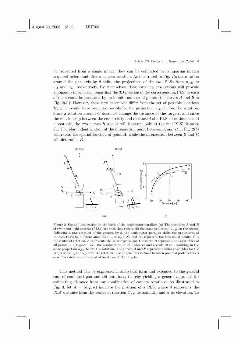
be recovered from a single image, they can be estimated by comparing images
acquired before and after a camera rotation. As illustrated in Fig. 2(a), a rotation
around the pan axis by θ shifts the projections of the two PLSs from uAB to
uA and uB, respectively. By themselves, these two new projections still provide
ambiguous information regarding the 3D position of the corresponding PLS, as each
of them could be produced by an infinite number of points (the curves A and B in
Fig. 2(b)). However, these new ensembles differ from the set of possible locations
H, which could have been responsible for the projection uAB before the rotation.
Since a rotation around C does not change the distance of the targets, and since
the relationship between the eccentricity and distance d of a PLS is continuous and
monotonic, the two curves H and A will intersect only at the real PLS’ distance
dA. Therefore, identification of the intersection point between A and H in Fig. 2(b)
will reveal the spatial location of point A, while the intersection between B and H
will determine B.
q
x
z
CS
N1
N2
B
A
uBuA
aA
~
20 40 60 80 1001
1.5
2
2.5
Distance [cm]
B
A
dA dB
H
Ecce
ntr
icity [
de
g]
x
z
CS
N1
N2
B
A
uAB
aA
dA
(a) (b)
BEFORE AFTER
L
Figure 2. Spatial localization on the basis of the oculomotor parallax. (a) The positions A and B
of two point-light sources (PLSs) are such that they yield the same projection uAB on the sensor.Following a pan rotation of the camera by θ, the oculomotor parallax shifts the projections ofthe two PLSs by different amounts (uA 6= uB). N1 and N2 represent the lens nodal points. C isthe center of rotation. S represents the sensor plane. (b) The curve H represents the ensembles ofall points in 2D space—i.e., the combination of all distances and eccentricities—resulting in thesame projection uAB before the rotation. The curves A and B represent similar ensembles for theprojections uA and uB after the rotation. The unique intersections between pre- and post-rotationsensembles determine the spatial locations of the targets.
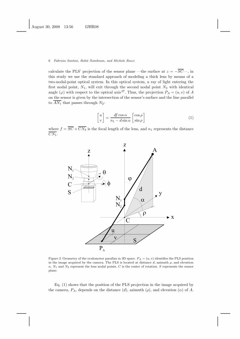
This method can be expressed in analytical form and extended to the general
case of combined pan and tilt rotations, thereby yielding a general approach for
estimating distance from any combination of camera rotations. As illustrated in
Fig. 3, let A = (d, ρ, α) indicate the position of a PLS, where d represents the
PLS’ distance from the center of rotation C, ρ its azimuth, and α its elevation. To
August 30, 2008 13:56 IJHR08
6 Fabrizio Santini, Rohit Nambisan, and Michele Rucci
calculate the PLS’ projection of the sensor plane —the surface at z = −SC—, in
this study we use the standard approach of modeling a thick lens by means of a
two-nodal-point optical system. In this optical system, a ray of light entering the
first nodal point, N1, will exit through the second nodal point N2 with identical
angle (ϕ) with respect to the optical axis27. Thus, the projection PA = (u, v) of A
on the sensor is given by the intersection of the sensor’s surface and the line parallel
to AN1 that passes through N2:
[u
v
]=
df cosα
n1 − d sin α
[cos ρ
sin ρ
](1)
where f = SC + CN2 is the focal length of the lens, and n1 represents the distance
CN1.
Figure 3. Geometry of the oculomotor parallax in 3D space. PA = (u, v) identifies the PLS positionin the image acquired by the camera. The PLS is located at distance d, azimuth ρ, and elevationα. N1 and N2 represent the lens nodal points. C is the center of rotation. S represents the sensorplane.
Eq. (1) shows that the position of the PLS projection in the image acquired by
the camera, PA, depends on the distance (d), azimuth (ρ), and elevation (α) of A.
August 30, 2008 13:56 IJHR08
Active 3D Vision in a Humanoid Robot 7
Both equations in (1) allow explicit expressions of the PLS distance as a function
of azimuth and eccentricity:[
d̂u
d̂v
]= n1
[u
f cos α cos ρ+u sin αv
f cos α sin ρ+v sin α
](2)
where the symbol d̂x indicates the estimate of the distance d based on the x co-
ordinate of the PLS (either u or v) in the image, acquired before a rotation of the
camera.
As shown in Fig. 3, the azimuth can be directly recovered from the two coordi-
nates of the PLS projection on the sensor:
ρ = arctan( v
u
)(3)
However, substitution of Eq. (3) in Eq. (1) still leaves the eccentricity of the target
undetermined. That is, as with the 2D example of Fig. 2, the PLS position cannot
be unequivocally recovered from a single image, as there are an infinite number of
possible locations which verify Eq. (1) for any given projection PA. These locations
are the points on the line AN1. These points yield the same projection even though
they differ in their distances and eccentricities.
To estimate the target’s eccentricity, we can follow the same approach of Fig. 2
and rotate the camera along the pan and tilt axes by angles θ and φ, respectively.
These rotations shift the projection of the PLS on the image to a new image location
P ′
A = (u′, v′) with coordinates:
[u′
v′
]= K
[cosα cos ρ cos θ + cosα sin ρ sin θ sin φ + sinα sin θ cosφ
cosα sin ρ cosφ − sin α sin φ
]
K =fd
n1 + d [cosα cos ρ sin θ − cosα sin ρ cos θ sin φ − sin α cos θ cosφ](4)
As with the equations in Eq. (1), the two equations in Eq. (4) also allow explicit
expressions of the PLS distance as a function of azimuth and eccentricity:
[d̂′ud̂′v
]= n1
u′
cos α cos ρ(f cos θ−u′ sin θ)+(u′ cos θ+f sin θ)(cosα sin ρ sin φ+sin α cos φ)
v′
cos α sin ρ(v′ cos θ sin φ+f cos φ)−v′ cos α cos ρ sin θ+v′ sin α cos θ cos φ−f sin α sin φ
(5)
where each of the two distance estimates, d̂′u and d̂′v , is based on one of the two
coordinates of the PLS in the image acquired after the rotation of the camera.
Since distances are measured with respect to the center of rotation, C, pan and
tilt rotations do not change the PLS’ distance d. That is, Eqs. (1) and (4) give four
August 30, 2008 13:56 IJHR08
8 Fabrizio Santini, Rohit Nambisan, and Michele Rucci
independent estimates (two from each projection coordinate) of the same distance
d. Equating the pairs of estimates obtained on the two image coordinates allows
determination of the PLS eccentricity:
α̂u =
α̂v =
arctan(
uf(cos ρ cos θ+sin ρ sin θ sin φ)+uu′(sin ρ cos θ sin φ−cos ρ sin θ)−u′f cos ρ
uu′(1−cos θ cos φ)−uf sin θ cos φ
)
arctan(
vv′(sin ρ cos θ sin φ−cos ρ sin θ)+fv sin ρ cos φ−v′f sin ρ
fv sin φ−vv′(cos θ cos φ−1)
)
(6)
where α̂x indicates the eccentricity estimate obtained on the basis of the x coordi-
nate (either u or v).
Substitution in Eq. (1) of the values for ρ and α obtained from Eqs. (6) and (3)
gives the distance of A as a function of the rotation amplitudes θ, φ, and the image
coordinates of the PLS projections before and after the rotation. Two separate
estimates are obtained on the basis of the two image axes:
d̂u =
d̂v =
n1 uf cos α̂u cos ρ+u sin α̂u
n1 vf cos α̂v sin ρ+v sin α̂v
(7)
Since these two estimates were calculated independently from each other, a
robust estimate of d can be obtained by means of a weighted average of the two
separate distances:
d̂ = cud̂u + cvd̂v (8)
In this study, separate estimates obtained on the two axes were combined by
using the method proposed by Cohen28. That is, given d̂u and d̂v, a single estimate
of distance d̂ was calculated using the following equation:
d̂ =σ2
u
σ2u + σ2
v
d̂v +σ2
v
σ2u + σ2
v
d̂u (9)
where σu and σv represent the standard deviations of the measurements of distance
obtained with the amplitudes of pan and tilt rotations, θ and φ, respectively: σu
= σu(θ), σv = σv(φ). That is, the weight assigned to a given estimate is inversely
proportional to its uncertainty. These standard deviations were measured with pre-
sentations of objects at various distances before performing the experiments, as
explained in Section 4. It can be shown that d̂ is an unbiased estimator of distance
with a standard deviation smaller than that of the individual estimates, d̂u and d̂v .
While this method yields perfect spatial localization in simulations, in practice
its application is limited by noise in the sensory measurements and inaccuracies in
motor control. Section 4 examines the impact of noise, and shows the application of
the method to an anthropomorphic robot replicating the eye movements of human
observers.
August 30, 2008 13:56 IJHR08
Active 3D Vision in a Humanoid Robot 9
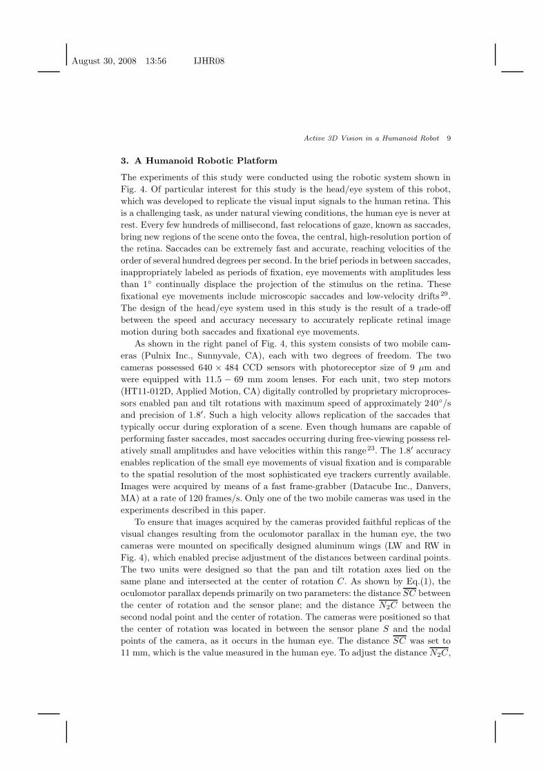
3. A Humanoid Robotic Platform
The experiments of this study were conducted using the robotic system shown in
Fig. 4. Of particular interest for this study is the head/eye system of this robot,
which was developed to replicate the visual input signals to the human retina. This
is a challenging task, as under natural viewing conditions, the human eye is never at
rest. Every few hundreds of millisecond, fast relocations of gaze, known as saccades,
bring new regions of the scene onto the fovea, the central, high-resolution portion of
the retina. Saccades can be extremely fast and accurate, reaching velocities of the
order of several hundred degrees per second. In the brief periods in between saccades,
inappropriately labeled as periods of fixation, eye movements with amplitudes less
than 1◦ continually displace the projection of the stimulus on the retina. These
fixational eye movements include microscopic saccades and low-velocity drifts 29.
The design of the head/eye system used in this study is the result of a trade-off
between the speed and accuracy necessary to accurately replicate retinal image
motion during both saccades and fixational eye movements.
As shown in the right panel of Fig. 4, this system consists of two mobile cam-
eras (Pulnix Inc., Sunnyvale, CA), each with two degrees of freedom. The two
cameras possessed 640 × 484 CCD sensors with photoreceptor size of 9 µm and
were equipped with 11.5 − 69 mm zoom lenses. For each unit, two step motors
(HT11-012D, Applied Motion, CA) digitally controlled by proprietary microproces-
sors enabled pan and tilt rotations with maximum speed of approximately 240◦/s
and precision of 1.8′. Such a high velocity allows replication of the saccades that
typically occur during exploration of a scene. Even though humans are capable of
performing faster saccades, most saccades occurring during free-viewing possess rel-
atively small amplitudes and have velocities within this range23. The 1.8′ accuracy
enables replication of the small eye movements of visual fixation and is comparable
to the spatial resolution of the most sophisticated eye trackers currently available.
Images were acquired by means of a fast frame-grabber (Datacube Inc., Danvers,
MA) at a rate of 120 frames/s. Only one of the two mobile cameras was used in the
experiments described in this paper.
To ensure that images acquired by the cameras provided faithful replicas of the
visual changes resulting from the oculomotor parallax in the human eye, the two
cameras were mounted on specifically designed aluminum wings (LW and RW in
Fig. 4), which enabled precise adjustment of the distances between cardinal points.
The two units were designed so that the pan and tilt rotation axes lied on the
same plane and intersected at the center of rotation C. As shown by Eq.(1), the
oculomotor parallax depends primarily on two parameters: the distance SC between
the center of rotation and the sensor plane; and the distance N2C between the
second nodal point and the center of rotation. The cameras were positioned so that
the center of rotation was located in between the sensor plane S and the nodal
points of the camera, as it occurs in the human eye. The distance SC was set to
11 mm, which is the value measured in the human eye. To adjust the distance N2C,
August 30, 2008 13:56 IJHR08
10 Fabrizio Santini, Rohit Nambisan, and Michele Rucci
LCRC
GY
GY
GX
GX
E
N1
C
Z
N2
Z
6.3mm11.00mm
S
Y
X
X X
Y YG
Y
MY
MX
GX
GY
MY
MX
GX
C C
LWRW
GY
GX
GX
GY
MY
MX
MX
MY
RWLW
Z Z
Y Y TO
PR
EA
R
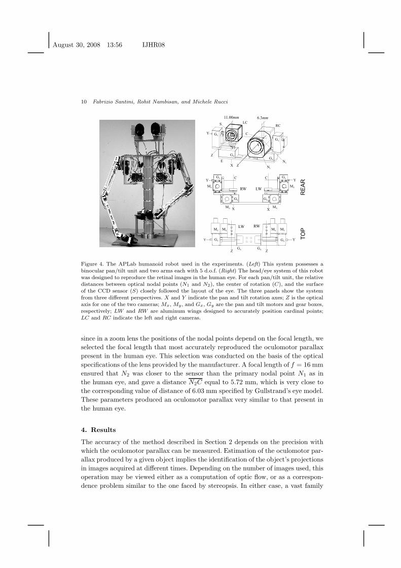
Figure 4. The APLab humanoid robot used in the experiments. (Left) This system possesses abinocular pan/tilt unit and two arms each with 5 d.o.f. (Right) The head/eye system of this robotwas designed to reproduce the retinal images in the human eye. For each pan/tilt unit, the relativedistances between optical nodal points (N1 and N2), the center of rotation (C), and the surfaceof the CCD sensor (S) closely followed the layout of the eye. The three panels show the systemfrom three different perspectives. X and Y indicate the pan and tilt rotation axes; Z is the opticalaxis for one of the two cameras; Mx, My, and Gx, Gy are the pan and tilt motors and gear boxes,respectively; LW and RW are aluminum wings designed to accurately position cardinal points;LC and RC indicate the left and right cameras.
since in a zoom lens the positions of the nodal points depend on the focal length, we
selected the focal length that most accurately reproduced the oculomotor parallax
present in the human eye. This selection was conducted on the basis of the optical
specifications of the lens provided by the manufacturer. A focal length of f = 16 mm
ensured that N2 was closer to the sensor than the primary nodal point N1 as in
the human eye, and gave a distance N2C equal to 5.72 mm, which is very close to
the corresponding value of distance of 6.03 mm specified by Gullstrand’s eye model.
These parameters produced an oculomotor parallax very similar to that present in
the human eye.
4. Results
The accuracy of the method described in Section 2 depends on the precision with
which the oculomotor parallax can be measured. Estimation of the oculomotor par-
allax produced by a given object implies the identification of the object’s projections
in images acquired at different times. Depending on the number of images used, this
operation may be viewed either as a computation of optic flow, or as a correspon-
dence problem similar to the one faced by stereopsis. In either case, a vast family
August 30, 2008 13:56 IJHR08
Active 3D Vision in a Humanoid Robot 11
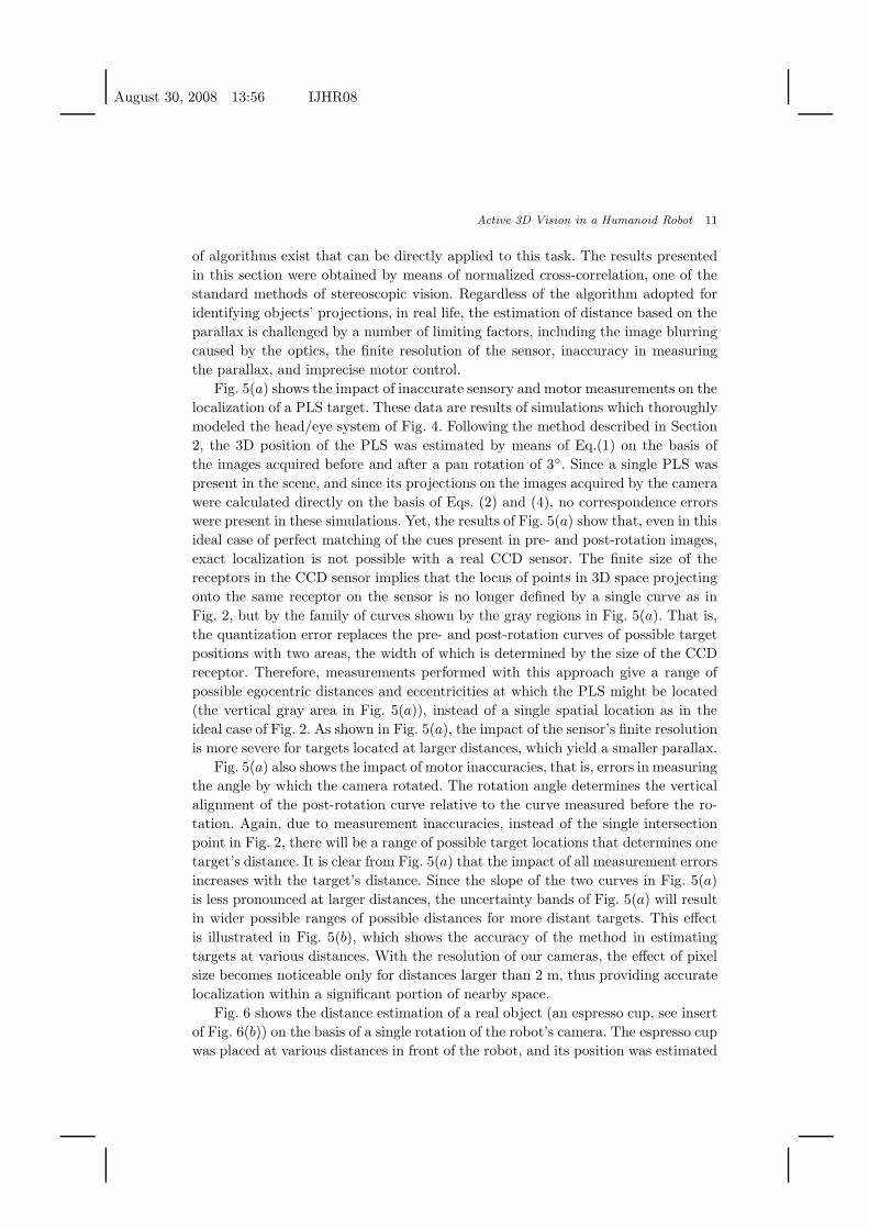
of algorithms exist that can be directly applied to this task. The results presented
in this section were obtained by means of normalized cross-correlation, one of the
standard methods of stereoscopic vision. Regardless of the algorithm adopted for
identifying objects’ projections, in real life, the estimation of distance based on the
parallax is challenged by a number of limiting factors, including the image blurring
caused by the optics, the finite resolution of the sensor, inaccuracy in measuring
the parallax, and imprecise motor control.
Fig. 5(a) shows the impact of inaccurate sensory and motor measurements on the
localization of a PLS target. These data are results of simulations which thoroughly
modeled the head/eye system of Fig. 4. Following the method described in Section
2, the 3D position of the PLS was estimated by means of Eq.(1) on the basis of
the images acquired before and after a pan rotation of 3◦. Since a single PLS was
present in the scene, and since its projections on the images acquired by the camera
were calculated directly on the basis of Eqs. (2) and (4), no correspondence errors
were present in these simulations. Yet, the results of Fig. 5(a) show that, even in this
ideal case of perfect matching of the cues present in pre- and post-rotation images,
exact localization is not possible with a real CCD sensor. The finite size of the
receptors in the CCD sensor implies that the locus of points in 3D space projecting
onto the same receptor on the sensor is no longer defined by a single curve as in
Fig. 2, but by the family of curves shown by the gray regions in Fig. 5(a). That is,
the quantization error replaces the pre- and post-rotation curves of possible target
positions with two areas, the width of which is determined by the size of the CCD
receptor. Therefore, measurements performed with this approach give a range of
possible egocentric distances and eccentricities at which the PLS might be located
(the vertical gray area in Fig. 5(a)), instead of a single spatial location as in the
ideal case of Fig. 2. As shown in Fig. 5(a), the impact of the sensor’s finite resolution
is more severe for targets located at larger distances, which yield a smaller parallax.
Fig. 5(a) also shows the impact of motor inaccuracies, that is, errors in measuring
the angle by which the camera rotated. The rotation angle determines the vertical
alignment of the post-rotation curve relative to the curve measured before the ro-
tation. Again, due to measurement inaccuracies, instead of the single intersection
point in Fig. 2, there will be a range of possible target locations that determines one
target’s distance. It is clear from Fig. 5(a) that the impact of all measurement errors
increases with the target’s distance. Since the slope of the two curves in Fig. 5(a)
is less pronounced at larger distances, the uncertainty bands of Fig. 5(a) will result
in wider possible ranges of possible distances for more distant targets. This effect
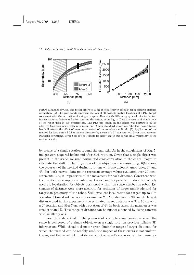
is illustrated in Fig. 5(b), which shows the accuracy of the method in estimating
targets at various distances. With the resolution of our cameras, the effect of pixel
size becomes noticeable only for distances larger than 2 m, thus providing accurate
localization within a significant portion of nearby space.
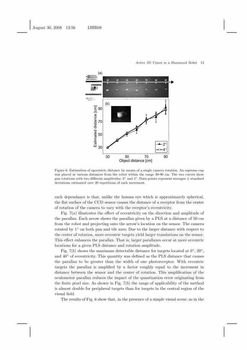
Fig. 6 shows the distance estimation of a real object (an espresso cup, see insert
of Fig. 6(b)) on the basis of a single rotation of the robot’s camera. The espresso cup
was placed at various distances in front of the robot, and its position was estimated
August 30, 2008 13:56 IJHR08
12 Fabrizio Santini, Rohit Nambisan, and Michele Rucci
350 550 750 950
100
101
Eccentr
icity [deg]
Distance [mm]
Before 3°
After 3°
(a)
0 500 1000 1500 20000
500
1000
1500
2000
2500
Est
imat
ed d
ista
nce
[mm
]Distance [mm]
(b)
Figure 5. Impact of visual and motor errors on using the oculomotor parallax for egocentric distanceestimation. (a) The gray bands represent the loci of all possible spatial locations of a PLS targetconsistent with the activation of a single receptor. Bands with different gray level refer to the twoimages acquired before and after rotating the sensor, as in Fig. 2. Data are results of simulationsof the robot used in our experiments. The PLS projection on the sensor was perturbed by anadditive Gaussian noise with zero mean and 2.5µm standard deviation. The two post-rotationbands illustrate the effect of inaccurate control of the rotation amplitude. (b) Application of themethod for localizing a PLS at various distances by means of a 3◦ pan rotation. Error bars representstandard deviations. Error bars are not visible for near targets due to the small variability of themeasurements.
by means of a single rotation around the pan axis. As in the simulations of Fig. 5,
images were acquired before and after each rotation. Given that a single object was
present in the scene, we used normalized cross-correlation of the entire images to
calculate the shift in the projection of the object on the sensor. Fig. 6(b) shows
the accuracy of the method during rotations with two different amplitudes, 2◦ and
4◦. For both curves, data points represent average values evaluated over 20 mea-
surements, i.e., 20 repetitions of the movement for each distance. Consistent with
the results from computer simulations, the oculomotor parallax produced extremely
accurate localization for objects positioned within the space nearby the robot. Es-
timates of distance were more accurate for rotations of larger amplitude and for
targets in proximity of the robot. Still, excellent localization for targets up to 1 m
was also obtained with a rotation as small as 2◦. At a distance of 90 cm, the largest
distance used in this experiment, the estimated target distance was 92±10 cm with
a 2◦ rotation and 89±7 cm with a rotation of 4◦. In both cases, the mean error was
smaller than 3%. This range of distance can be further extended by using cameras
with smaller pixels.
These data show that in the presence of a simple visual scene, as when the
scene is composed of a single object, even a single rotation provides reliable 3D
information. While visual and motor errors limit the range of target distances for
which the method can be reliably used, the impact of these errors is not uniform
throughout the visual field, but depends on the target’s eccentricity. The reason for
August 30, 2008 13:56 IJHR08
Active 3D Vision in a Humanoid Robot 13
(a)
(b)
Figure 6. Estimation of egocentric distance by means of a single camera rotation. An espresso cupwas placed at various distances from the robot within the range 30-90 cm. The two curves showpan rotations with two different amplitudes: 2◦ and 4◦. Data points represent averages ± standarddeviations estimated over 20 repetitions of each movement.
such dependance is that, unlike the human eye which is approximately spherical,
the flat surface of the CCD sensor causes the distance of a receptor from the center
of rotation of the camera to vary with the receptor’s eccentricity.
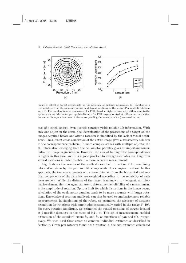
Fig. 7(a) illustrates the effect of eccentricity on the direction and amplitude of
the parallax. Each arrow shows the parallax given by a PLS at a distance of 50 cm
from the robot and projecting onto the arrow’s location on the sensor. The camera
rotated by 1◦ on both pan and tilt axes. Due to the larger distance with respect to
the center of rotation, more eccentric targets yield larger translations on the sensor.
This effect enhances the parallax. That is, larger parallaxes occur at more eccentric
locations for a given PLS distance and rotation amplitude.
Fig. 7(b) shows the maximum detectable distance for targets located at 0◦, 20◦,
and 40◦ of eccentricity. This quantity was defined as the PLS distance that causes
the parallax to be greater than the width of one photoreceptor. With eccentric
targets the parallax is amplified by a factor roughly equal to the increment in
distance between the sensor and the center of rotation. This amplification of the
oculomotor parallax reduces the impact of the quantization error originating from
the finite pixel size. As shown in Fig. 7(b) the range of applicability of the method
is almost double for peripheral targets than for targets in the central region of the
visual field.
The results of Fig. 6 show that, in the presence of a simple visual scene, as in the
August 30, 2008 13:56 IJHR08
14 Fabrizio Santini, Rohit Nambisan, and Michele Rucci
−20 −10 0 10 20
−20
−10
0
10
20
Projection u [mm]
Pro
ject
ion
v [m
m]
50
50
55
5560
60
60
65
65
65
70 70
70
70
75
75
(a)
0 2 4 6100
150
200
250
300
350
400
Max
imum
Dis
tanc
e [c
m]
Saccade [deg]
0°20°40°
(b)
Figure 7. Effect of target eccentricity on the accuracy of distance estimation. (a) Parallax of aPLS at 50 cm from the robot projecting on different locations on the sensor. Pan and tilt rotationswere 1◦. The parallax is more pronounced for PLS placed at higher eccentricity with respect to theoptical axis. (b) Maximum perceptible distance for PLS targets located at different eccentricities.Isocontour lines join locations of the sensor yielding the same parallax (measured in µm).
case of a single object, even a single rotation yields reliable 3D information. With
only one object in the scene, the identification of the projections of a target on the
images acquired before and after a rotation is simplified by the lack of visual occlu-
sions. Thus, direct cross-correlation of the entire image gives a satisfactory solution
to the correspondence problem. In more complex scenes with multiple objects, the
3D information emerging from the oculomotor parallax gives an important contri-
bution to image segmentation. However, the risk of finding false correspondences
is higher in this case, and it is a good practice to average estimates resulting from
several rotations in order to obtain a more accurate measurement.
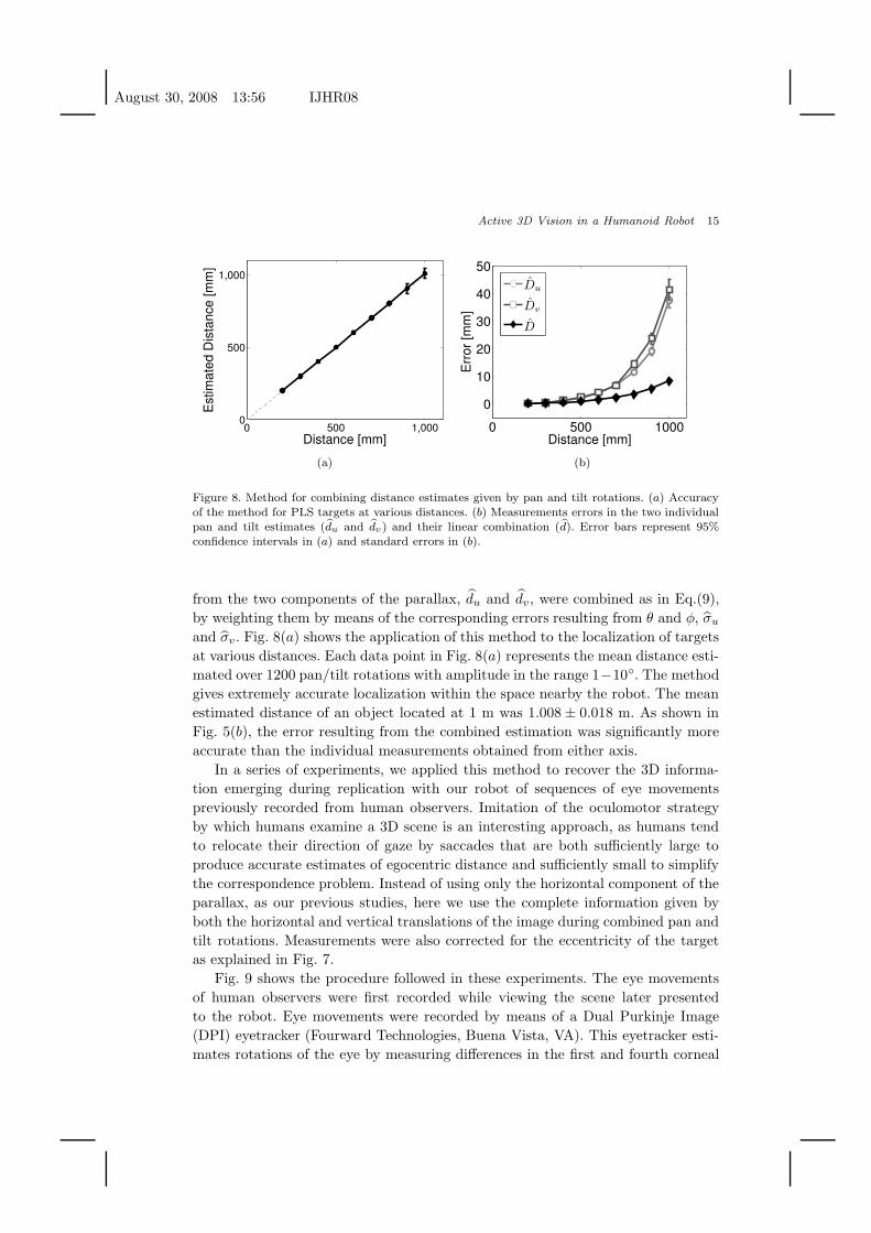
Fig. 8 shows the results of the method described in Section 2 for combining
information given by the pan and tilt components of a complex rotation. In this
approach, the two measurements of distance obtained from the horizontal and ver-
tical components of the parallax are weighted according to the reliability of each
measurement. While the distance of the target is unknown to the agent, an infor-
mative element that the agent can use to determine the reliability of a measurement
is the amplitude of rotation. Up to a limit for which distortions in the image occur,
calculation of the oculomotor parallax tends to be more accurate with larger rota-
tions. Knowledge of rotation amplitude can thus be used to emphasize more reliable
measurements. In simulations of the robot, we examined the accuracy of distance
estimation for rotations with amplitudes systematically varied in the range 1◦-10◦.
For every rotation amplitude, we estimated the spatial positions of targets located
at 9 possible distances in the range of 0.2-1 m. This set of measurements enabled
estimation of the standard errors σ̂u and σ̂v as functions of pan and tilt, respec-
tively. We then used these errors to combine individual estimates as described in
Section 2. Given pan rotation θ and a tilt rotation φ, the two estimates calculated
August 30, 2008 13:56 IJHR08
Active 3D Vision in a Humanoid Robot 15
0 500 1,0000
500
1,000
Distance [mm]
Est
imat
ed D
ista
nce
[mm
]
(a)
0 500 1000
0
10
20
30
40
50
Distance [mm]
Err
or [m
m]
D̂u
D̂v
D̂
(b)
Figure 8. Method for combining distance estimates given by pan and tilt rotations. (a) Accuracyof the method for PLS targets at various distances. (b) Measurements errors in the two individualpan and tilt estimates (d̂u and d̂v) and their linear combination (d̂). Error bars represent 95%confidence intervals in (a) and standard errors in (b).
from the two components of the parallax, d̂u and d̂v, were combined as in Eq.(9),
by weighting them by means of the corresponding errors resulting from θ and φ, σ̂u
and σ̂v . Fig. 8(a) shows the application of this method to the localization of targets
at various distances. Each data point in Fig. 8(a) represents the mean distance esti-
mated over 1200 pan/tilt rotations with amplitude in the range 1−10◦. The method
gives extremely accurate localization within the space nearby the robot. The mean
estimated distance of an object located at 1 m was 1.008 ± 0.018 m. As shown in
Fig. 5(b), the error resulting from the combined estimation was significantly more
accurate than the individual measurements obtained from either axis.
In a series of experiments, we applied this method to recover the 3D informa-
tion emerging during replication with our robot of sequences of eye movements
previously recorded from human observers. Imitation of the oculomotor strategy
by which humans examine a 3D scene is an interesting approach, as humans tend
to relocate their direction of gaze by saccades that are both sufficiently large to
produce accurate estimates of egocentric distance and sufficiently small to simplify
the correspondence problem. Instead of using only the horizontal component of the
parallax, as our previous studies, here we use the complete information given by
both the horizontal and vertical translations of the image during combined pan and
tilt rotations. Measurements were also corrected for the eccentricity of the target
as explained in Fig. 7.
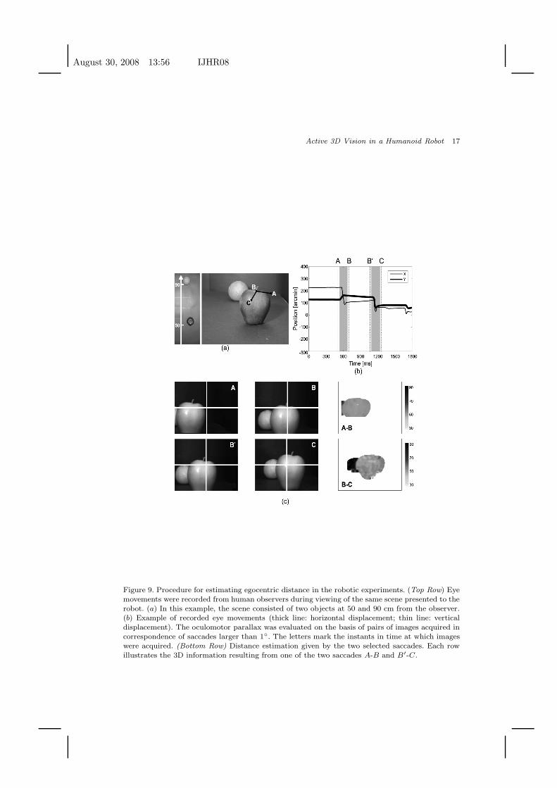
Fig. 9 shows the procedure followed in these experiments. The eye movements
of human observers were first recorded while viewing the scene later presented
to the robot. Eye movements were recorded by means of a Dual Purkinje Image
(DPI) eyetracker (Fourward Technologies, Buena Vista, VA). This eyetracker esti-
mates rotations of the eye by measuring differences in the first and fourth corneal
August 30, 2008 13:56 IJHR08
16 Fabrizio Santini, Rohit Nambisan, and Michele Rucci
reflections—the Purkinje images—of an infrared beam. It does not interfere with
normal vision, and allows for accurate determination of eye movements over a large
visual field without any physical attachment to the eye. Recorded traces of eye move-
ments were then preprocessed to identify saccades and periods of fixation. Saccades
larger than 1◦ were selected to be replicated by the robot. A spatial correspon-
dence between the voltages generated by the eyetracker and the motor commands
for the robot was established by means of a preliminary calibration in which both
the subject and the robot fixated on a number of selected points in the scene. This
calibration ensured that the images acquired by the camera were centered on the
points fixated by the subject.
Fig. 9(c) illustrates the method by which the 3D information emerging from con-
secutive saccades was combined. In this example, the scene consisted of two objects,
an apple and an orange located at 50 cm and 90 cm from the robot, respectively.
The robot moved following a sequence of recorded eye movements composed of two
saccades: first, a saccade from A to B with an approximate amplitude of 2◦, and a
second saccade from B′ (the point close to B reached at the end of fixation) to A
with an approximate amplitude of 1.5◦. The first saccade primarily involved a pan
rotation, while the second saccade consisted of both pan and tilt rotations.
The oculomotor parallax at various locations in the scene was evaluated by
subdividing each pre-saccadic image into 20×20 rectangular patches, each composed
of 32× 24 pixels. The corresponding location of a patch in the post-saccade image
was estimated by means of normalized cross-correlation. Patches were assumed to
have moved out of the post-saccade image when cross-correlation scores were below
a pre-specified threshold value of 0.85. In this case, the parallax of the corresponding
image patch was left undetermined. Every sample of the oculomotor parallax was
subsequently converted into an estimate of distance by means of the model described
in Section 2. In this way, an estimate of distance was obtained for a number of
equivalently spaced locations in the image. All estimates at the same spatial location
with respect to the robot were averaged across saccades. The cross-correlation of
the frames A-B, and B′-C yielded over 10,000 measurements of distance for the
apple and approximately 2000 for the orange. The method was able to correctly
estimate the distance of the two objects, giving an average distance of 53 ± 8 cm
for the apple and 92± 10 cm for the orange.
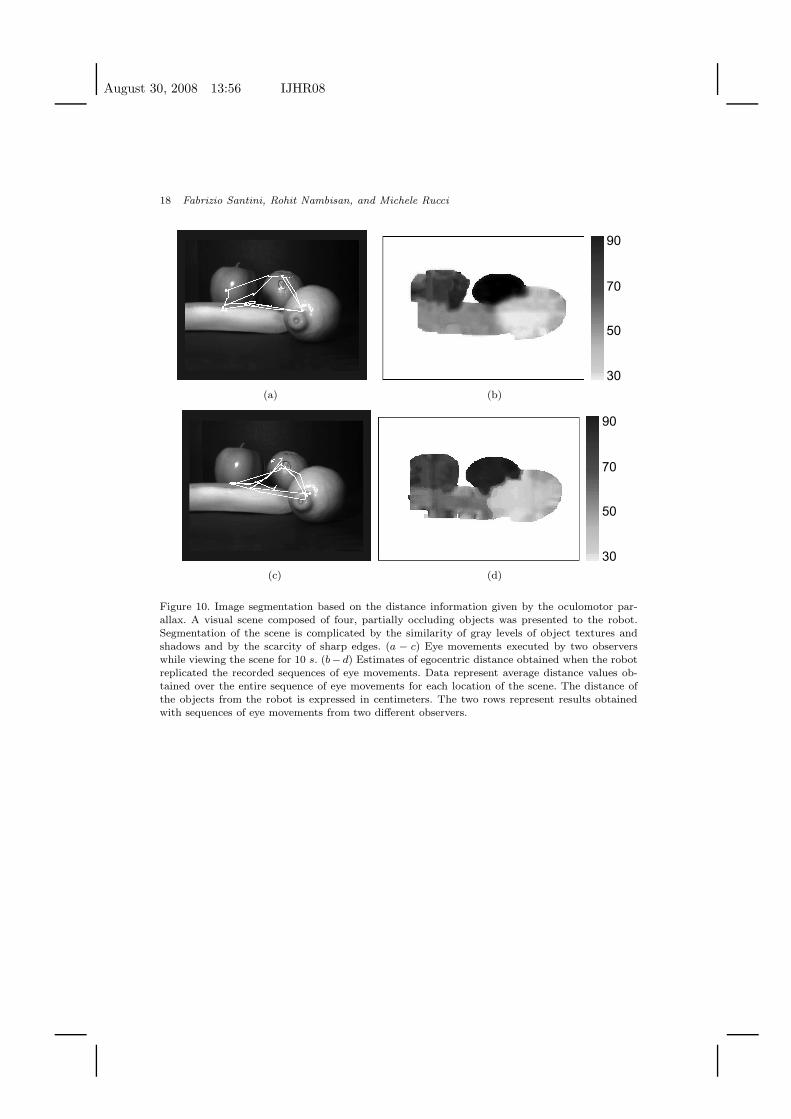
Fig. 10 shows results obtained from examining a complex 3D scene by means of
10-s sequences of eye movements. The scene was composed of four fruits (an apple,
an orange, a banana, and a lemon) located at various distances. Visual occlusions
and shadows, together with similarities in the textures of the objects made segmen-
tation of the scene extremely difficult in the black and white images acquired by the
camera. The two rows of Fig. 10 show results obtained from replicating two different
sequences of eye movements. Although the two observers looked at different points
in the scene, they performed the same number of saccades (N = 13). The average
amplitude of saccades was 2.4± 1.3◦ in trace 1, and 2.5± 1.1◦ in trace 2. As in the
example of Fig. 9, the oculomotor parallax at various locations in the scene was
August 30, 2008 13:56 IJHR08
Active 3D Vision in a Humanoid Robot 17
Figure 9. Procedure for estimating egocentric distance in the robotic experiments. (Top Row) Eyemovements were recorded from human observers during viewing of the same scene presented to therobot. (a) In this example, the scene consisted of two objects at 50 and 90 cm from the observer.(b) Example of recorded eye movements (thick line: horizontal displacement; thin line: verticaldisplacement). The oculomotor parallax was evaluated on the basis of pairs of images acquired incorrespondence of saccades larger than 1◦. The letters mark the instants in time at which imageswere acquired. (Bottom Row) Distance estimation given by the two selected saccades. Each rowillustrates the 3D information resulting from one of the two saccades A-B and B′-C.
August 30, 2008 13:56 IJHR08
18 Fabrizio Santini, Rohit Nambisan, and Michele Rucci
(a) (b)
(c)
30
50
70
90
(d)
Figure 10. Image segmentation based on the distance information given by the oculomotor par-allax. A visual scene composed of four, partially occluding objects was presented to the robot.Segmentation of the scene is complicated by the similarity of gray levels of object textures andshadows and by the scarcity of sharp edges. (a − c) Eye movements executed by two observerswhile viewing the scene for 10 s. (b− d) Estimates of egocentric distance obtained when the robotreplicated the recorded sequences of eye movements. Data represent average distance values ob-tained over the entire sequence of eye movements for each location of the scene. The distance ofthe objects from the robot is expressed in centimeters. The two rows represent results obtainedwith sequences of eye movements from two different observers.
August 30, 2008 13:56 IJHR08
Active 3D Vision in a Humanoid Robot 19
evaluated on the basis of normalized cross-correlation of rectangular 32 × 24 pixel
patches. Every sample of the oculomotor parallax was converted into an estimate
of distance by means of the model. Data points at the same spatial location were
averaged over the 13 saccades of each sequence.
The two panels on the right of Fig. 10 show maps of egocentric distance. Each
pixel in these maps represent the mean distance estimated at the corresponding
location in the scene. The white areas in these images correspond to the uniform
surfaces of the table and the background, which did not produce a measurable
parallax. As shown by these figures, the oculomotor parallax emerging during repli-
cation of human eye movements enabled accurate segmentation of the scene into
individual objects. Table 4 reports the average distance measured over all patches
composing each object. Since the oculomotor parallax could only be measured for
saccades that maintained an object within the field of view of the camera, averages
were evaluated over different numbers of measurements for each object. These num-
bers show that the method produced very accurate estimates of distances when a
sufficient number of measurements were available.
Table 1. Estimated distances of the four objects in thescene of Fig. 10. The number of measurements avail-able for each object are given in parentheses.
Object Distance Trace 1 Trace 2(cm)
Lemon 48 47 ± 3 (3758) 45 ± 5 (3637)Banana 60 56 ± 8 (5152) 50 ± 12 (4341)Apple 70 69 ± 3 (3119) 64 ± 8 (3265)Orange 85 80 ± 4 (1141) 86 ± 12 (1364)
5. Conclusions
Many operations in robotics require knowledge of the 3D structure of the scene
surrounding the agent. The results of this study show that the parallax caused by
rotations of the cameras yield accurate 3D information in a robot that actively
controls its gaze. Thus, in a humanoid robot, the oculomotor parallax can be added
to the list of reliable 3D visual cues together with more traditionally investigated
cues, such as stereopsis and vergence. All these cues can be integrated to yield
robust representations of 3D scenes.
The results presented in this article builds upon our previous work addressing the
feasibility of replicating human eye movements in an anthropomorphic robot 24;25.
These previous studies have shown that pan rotations, with amplitudes similar
to horizontal eye movements in humans, yield a 1D parallax that can be reliably
detected. Based on these previous results, we developed a new pan/tilt unit, which
enabled more accurate replication of human eye movements. The results presented
August 30, 2008 13:56 IJHR08
20 Fabrizio Santini, Rohit Nambisan, and Michele Rucci
in this paper were obtained by means of this unit. The present study provides a
full characterization of the 2D oculomotor parallax emerging during replication of
human eye movements, its dependence on eccentricity, and the influences of visual
and motor errors. Furthermore, we have described a method for efficiently combining
independent pan and tilt estimates of distance and examined its accuracy in real-
world experiments. The results presented in this paper show that the oculomotor
parallax gives very accurate estimation of egocentric distance within the space in
proximity to the agent. This cue can be used to control local motor actions, such
as object reaching and grasping.
In biological systems, sensory perception and motor control are closely tied.
Organisms extensively exploit the changes in sensory inputs produced by planned
actions to gain useful information about the structure of the scene 8;9. Motor con-
tributions to perceptual computations have been shown in many species, ranging
from insects30 to birds31. Like most species, humans are not passively exposed
to the incoming flow of sensory data, but actively seek useful information. Many
studies have shown computational contributions of oculomotor activity to 3D vi-
sion. For example, in stereoscopic vision, eye movements lighten the computational
load by limiting the motion of the epipolar lines, which allows stereopsis to get by
with smaller search zones32. Eye movement signals are also necessary for the un-
ambiguous interpretation of motion parallax33. Extra-retinal signals arising from
eye-muscle proprioception and/or from the efference copy of eye-movement com-
mands contribute to the perception of absolute distance from accommodation 34
and vergence35. Extra-retinal signals also calibrate and modify binocular dispar-
ity36. Furthermore, saccades produce 3D information both by rotating the orien-
tation of stationary surfaces37 and by means of the oculomotor parallax described
in this study20–22. The emerging field of humanoid robotics needs to pay close at-
tention to the tight interaction between visual and motor processes exhibited by
primates.
In contrast with the way organisms perform visual tasks, computer vision stud-
ies often focus on the analysis of static images. Yet, a number of pioneering studies
pointed out that a tight link between behavior and perception may be a key factor
for the development of more efficient vision algorithms38–40. Following these ob-
servations, a variety of active approaches for 3D vision have been proposed 41–44.
Many studies have focused on the parallax that emerges during navigation of a
mobile platform11–16. The work presented in this paper shows that a more subtle
behavior, such as oculomotor activity, also gives important 3D cues.
The APLab humanoid robot used in the experiments of this paper is the lat-
est version an anthropomorphic robotic platform developed as part of our research
program on the embedment in behaving automata of computational models of the
brain. During the last decade, interest in the use of robotic systems has been in-
creasingly growing within the neuroscience community45, as neuroscientists have
begun to recognize that robots offer a means to quantitatively test and analyze
brain theories46–49. Whereas computational models of neural systems are often
August 30, 2008 13:56 IJHR08
REFERENCES 21
tested by simplified sensory inputs in simulations, the coupling of neuronal mod-
els with robotic systems enables stimulation of these models with realistic sensory
signals, as well as the introduction of phenotypic and environmental constraints
similar to those that animals must face during development. Furthermore, use of
robotic systems gives exposure to the sensory signals that occur during behavior.
These signals are difficult to model in computer simulations. Ongoing projects in
the APLab are extending the work presented in this paper by introducing other
types of motor activity and by investigating the self-calibration of 3D visual cues
by means of learning.
Acknowledgment
This work was supported by the National Science Foundation grant CCF-0720691.
References
1. I. Howard and B. Rogers, Seeing in Depth. Thornhill, Ontario, Canada: I
Porteous, 2002.
2. N. Ayache, Artificial Vision for Mobile Robots: Stereo Vision and Multisensory
Perception. Cambridge, Massachusetts, U.S.A.: MIT Press, 1991.
3. O. Faugeras, The Geometry of Multiple Images: The Laws that Govern the For-
mation of Multiple Images of a Scene and Some of Their Applications. Cam-
bridge, Massachusetts, U.S.A.: MIT Press, 2001.
4. A. Torralba and A. Oliva, “Depth estimation from image structure,” IEEE
Trans. Pattern Anal. Mach. Intell., vol. 24, no. 9, pp. 1226–1238, 2002.
5. B. Super and A. Bovik, “Shape from texture using local spectral moments,”
IEEE Trans. Pattern Anal. Mach. Intell., vol. 17, no. 4, pp. 333–343, 1995.
6. R. Zhang, P. Tsai, J. Cryer, and M. Shah, “Shape from shading: A survey,”
IEEE Trans. Pattern Anal. Mach. Intell., vol. 21, no. 8, pp. 690–706, 1999.
7. A. Pentland, “A new sense for depth of field,” IEEE Trans. Pattern Anal. Mach.
Intell., vol. 9, pp. 523–531, 1987.
8. H. von Helmholtz, Treatise on Physiological Optics. Dover, New York, U.S.A.:
J. P. C. Southall (Ed.), 1909/1962.
9. E. Gibson, J. Gibson, O. Smith, and H. Flock, “Motion parallax as a determi-
nant of perceived depth,” J. Exp. Psychol., vol. 58, pp. 40–51, 1959.
10. T. Brodsky, C. Fermller, and Y. Aloimonos, “Structure from motion: Beyond
the epipolar constraint,” Int. J. Comp. Vis., vol. 37, no. 3, pp. 231–258, June
2000.
11. G. Sandini and M. Tistarelli, “Active tracking strategy for monocular depth in-
ference over multiple frames,” IEEE Trans. Pattern Anal. Mach. Intell., vol. 12,
pp. 13–27, 1990.
12. A. Dalmia and M. Trivedi, “High-speed extraction of 3D structure of selectable
quality using a translating camera,” Comput. Vis. Image Und., vol. 64, no. 1,
pp. 97–110, 1996.
August 30, 2008 13:56 IJHR08
22 REFERENCES
13. Y. Hung and H. Ho, “A Kalman filter approach to direct depth estimation incor-
porating surface structure,” IEEE Trans. Pattern Anal. Mach. Intell., vol. 21,
no. 6, pp. 570–575, 1999.
14. Y. Aloimonos and Z. Duric, “Estimating the heading direction using normal
flow,” Int. J. Comp. Vision, vol. 13, pp. 33–56, 1994.
15. G. Adiv, “Determining three-dimensional motion and structure from optical
flow generated by several moving objects,” IEEE Trans. Pattern Anal. Mach.
Intell., vol. 7, no. 4, pp. 384–401, 1985.
16. J. Weng, T. Huang, and N. Ahuja, Motion and Structure From Image Sequences.
New York, U.S.A.: Springer-Verlag, 1993.
17. J. Oliensis, “A critique of structure-from-motion algorithms,” Comput. Vis.
Image Und., vol. 80, no. 2, pp. 172–214, 2000.
18. J. Pettigrew, S. Collin, and M. Ott, “Convergence of specialised behaviour, eye
movements and visual optics in the sandlance (teleostei) and the chameleon
(reptilia),” Curr. Biol., vol. 9, no. 8, pp. 421–424, 1999.
19. M. Land, “Fast-focus telephoto eye,” Nature, vol. 373, pp. 658–659, 1995.
20. I. Hadami, G. Ishai, and M. Gur, “Visual stability and space perception in
monocular vision: Mathematical model,” J. Opt. Soc. Am. A, vol. 70, pp. 60–
65, 1980.
21. A. Mapp and H. Ono, “The rhino-optical phenomenon: Ocular parallax and the
visible field beyond the nose,” Vision Res., vol. 26, pp. 1163–1165, 1986.
22. G. Bingham, “Optical flow from eye movement with head immobilized: Ocular
occlusion beyond the nose,” Vision Res., vol. 33, no. 5/6, pp. 777–789, 1993.
23. A. Bahill, D. Adler, and L. Stark, “Most naturally occurring human saccades
have magnitudes of 15 degrees or less,” Invest. Ophth., vol. 14, no. 6, pp. 468–
469, 1975.
24. F. Santini and M. Rucci, “Active estimation of distance in a robotic system
that replicates human eye movements,” Robot. Auton. Syst., vol. 55, no. 2, pp.
107–121, 2007.
25. F. Santini and M.Rucci, “Depth perception in an anthropomorphic robot
that replicates human eye movements,” in IEEE International Conference on
Robotics and Automation, 2006.
26. A. Gullstrand, Appendices to Part 1: The Optical System of the Eye. Hamburg,
Germany: Voss, 1909, pp. 350–358.
27. P. Mouroulis and J. MacDonald, Geometrical Optics and Optical Design. Ox-
ford, England: Oxford University Press, 1997.
28. A. Cohen, “Combining estimates of location,” Journal of the American Statis-
tical Association, vol. 71, no. 353, pp. 172–175, March 1976.
29. M. Rucci, R. Iovin, M. Poletti, and F. Santini, “Miniature eye movements en-
hance fine spatial detail,” Nature, vol. 447, no. 7146, pp. 851–854, 2007.
30. M. Lehrer and M. V. Srinivasan, “Active vision in honeybees: Task-oriented
suppression of an innate behaviour,” Vision Res., vol. 34, no. 4, pp. 511–516,
1994.
August 30, 2008 13:56 IJHR08
REFERENCES 23
31. M. S. Dawkins and A. Woodington, “Pattern recognition and active vision in
chickens,” Nature, vol. 403, no. 6770, pp. 652–655, 2000.
32. K. Schreiber, J. D. Crawford, M. Fetter, and D. Tweed, “The motor side of
depth vision,” Nature, vol. 410, no. 6830, pp. 819–822, 2001.
33. M. Nawrot, “Eye movements provide the extra-retinal signal required for the
perception of depth from motion parallax,” Vision Res., vol. 43, no. 14, pp.
1553–1562, 2003.
34. H. Wallach and L. Floor, “The use of size matching to demonstrate the ef-
fectiveness of accommodation and convergence as cues for distance,” Percept.
Psychophys., vol. 10, pp. 423–428, 1971.
35. J. M. Foley and W. Richards, “Effects of voluntary eye movement and conver-
gence on the binocular appreciation of depth,” Percept. Psychophys., vol. 11,
pp. 423–427, 1972.
36. B. Backus, M. Banks, R. V. Ee, and J. Crowell, “Horizontal and vertical dispar-
ity, eye position, and stereoscopic slant perception,” Vision Res., vol. 39, no. 6,
pp. 1143–1170, 1999.
37. M. Wexler, “Anticipating the three-dimensional consequences of eye move-
ments,” Proc. Natl. Acad. Sci. USA, vol. 102, no. 4, pp. 1246–1251, 2005.
38. Y. Aloimonos, I. Weiss, and A. Bandyopadhyay, “Active vision,” Int. J. Comp.
Vision, vol. 2, pp. 333–356, 1988.
39. R. Bajcsy, “Active perception,” Proc. IEEE, vol. 76, no. 8, pp. 996–1005, 1988.
40. D. Ballard, “Animate vision,” Artif. Intell., vol. 48, pp. 57–86, 1991.
41. R. Jarvis, “A perspective on range-finding techniques for computer vision,”
IEEE Trans. Pattern Anal. Mach. Intell., vol. 5, pp. 122–139, 1983.
42. W. Klarquist and A. Bovik, “FOVEA: A foveated vergent active stereo vision
system for dynamic three-dimensional scene recovery,” IEEE Trans. Robot. Au-
tom., vol. 14, no. 5, pp. 755–770, 1998.
43. M. Bjorkman and J. Eklundh, “Real-time epipolar geometry estimation of
binocular stereo heads,” IEEE Trans. Pattern Anal. Mach. Intell., vol. 24, no. 3,
pp. 425–432, 2002.
44. A. Rajagopalan, “Depth estimation and image restoration using defocused
stereo pairs,” IEEE Trans. Pattern Anal. Mach. Intell., vol. 26, no. 11, pp.
1521–1525, 2004.
45. M. Lungarella, G. Metta, R. Pfeifer, and G. Sandini, “Developmental robotics:
A survey,” Connection Science, vol. 15, no. 4, pp. 151–190, 2003.
46. R. Beer, H. Chiel, R. Quinn, and R. Ritzmann, “Biorobotic approaches to the
study of motor systems,” Curr. Opinion in Neurobio., vol. 8, no. 6, pp. 777–782,
1998.
47. M. Rucci, G. Edelman, and J. Wray, “Adaptation of orienting behavior: From
the barn owl to a robotic system,” IEEE Trans. Robot. Autom., vol. 15, no. 1,
pp. 96–110, 1999.
48. O. Sporns and W. Alexander, “Neuromodulation and plasticity in an au-
tonomous robot,” Neur. Networks, vol. 15, no. 4-6, pp. 761–774, 2002.

August 30, 2008 13:56 IJHR08
24 REFERENCES
49. P. Verschure, T. Voegtlin, and R. Douglas, “Environmentally mediated synergy
between perception and behaviour in mobile robots,” Nature, vol. 425, pp. 620–
624, 2003.
August 30, 2008 13:56 IJHR08
REFERENCES 25
Fabrizio Santini received his M.Sc. degree in Computer Sci-
ence Engineering from the University of Rome ”La Sapienza”, Italy in 1999, and
his Ph.D. degree in Computer Science and Robotics from the University of Flo-
rence, Italy in 2004. In 2002 he joined the Active Perception Laboratory at Boston
University, first as a Visiting Scholar and then as a Research Associate. At Boston
University, Dr. Santini has been working on the development of a humanoid robot
with a vision system that models the brain of primates. Dr. Santini’s research in-
terests include biomimetic robotics, machine learning, and evolutionary hardware.
Rohit Nambisan received his B.A. degree in Cognitive Sci-
ence from the University of California, Berkeley, U.S.A, in 2003. In 2008, he joined
the Active Perception Laboratory at Boston University as a graduate student re-
searcher. Mr. Nambisan has been working on extending the functionality of the AP
Lab Humanoid robot to include head movements. Mr. Nambisan’s research interests
include biomimetic robotics, active vision, and sensorimotor integration.
Michele Rucci is Director of the Active Perception Labo-
ratory at Boston University, a facility dedicated to the analysis of the perceptual
influences of behavior. He earned his Laurea and Ph.D. in biomedical engineering
from the University of Florence and the Scuola Superiore S. Anna in Pisa, respec-
tively. Before joining Boston University, he was a Fellow in Computational Neu-
roscience at the Neurosciences Institute in San Diego. Dr. Rucci’s research follows
an interdisciplinary approach that integrates experiments in visual neuroscience
with computational models of the brain and the embodiment of neuronal models
in robotic systems. His work has raised specific hypotheses regarding the influences
of eye movements during visual development and in the neural encoding of visual
information. This research has also demonstrated the involvement of fixational eye
movements in fine spatial vision, produced a new system for experimental studies
of visual neuroscience, and led to the development of robots directly controlled by
models of the brain. Dr. Rucci is the author/coauthor of over 90 research publica-
tions, one of which received the Best Vision Paper Award at the IEEE Conference
on Robotics and Automation in 2006.


![Human-Like Reflexes for Robotic Manipulation Using Leaky ...vigir.missouri.edu/~gdesouza/Research/Conference_CDs/IEEE_IROS_… · architecture for humanoid robots [6], based on a](https://img.pdfslide.us/doc/110x75/5f7cb4e53be7df58c015923a/human-like-reflexes-for-robotic-manipulation-using-leaky-vigir-gdesouzaresearchconferencecdsieeeiros.jpg)