Embed Size (px)
Citation preview
FEBRUARY/MARCH 2017 VOLUME 13 ISSUE NO.166
TECHNICAL FEATURE l VAPOUR RECOVERY
Recovery of hydrocarbon vapours has been an integral part of fuel loading operations for decades. Since instal-
lation of vapour recovery units (VRU) began on a large scale in the 90s, the principle of adsorption on activated carbon followed by regeneration under vacuum has become the best available technology for the vast majority of applications. It is estimated that more than 95% of all new VRUs worldwide are based on this process. When designed properly, the vacuum-regenerated activated carbon systems are very efficient, economical, safe and extremely reliable – even with a low mainte-nance effort.
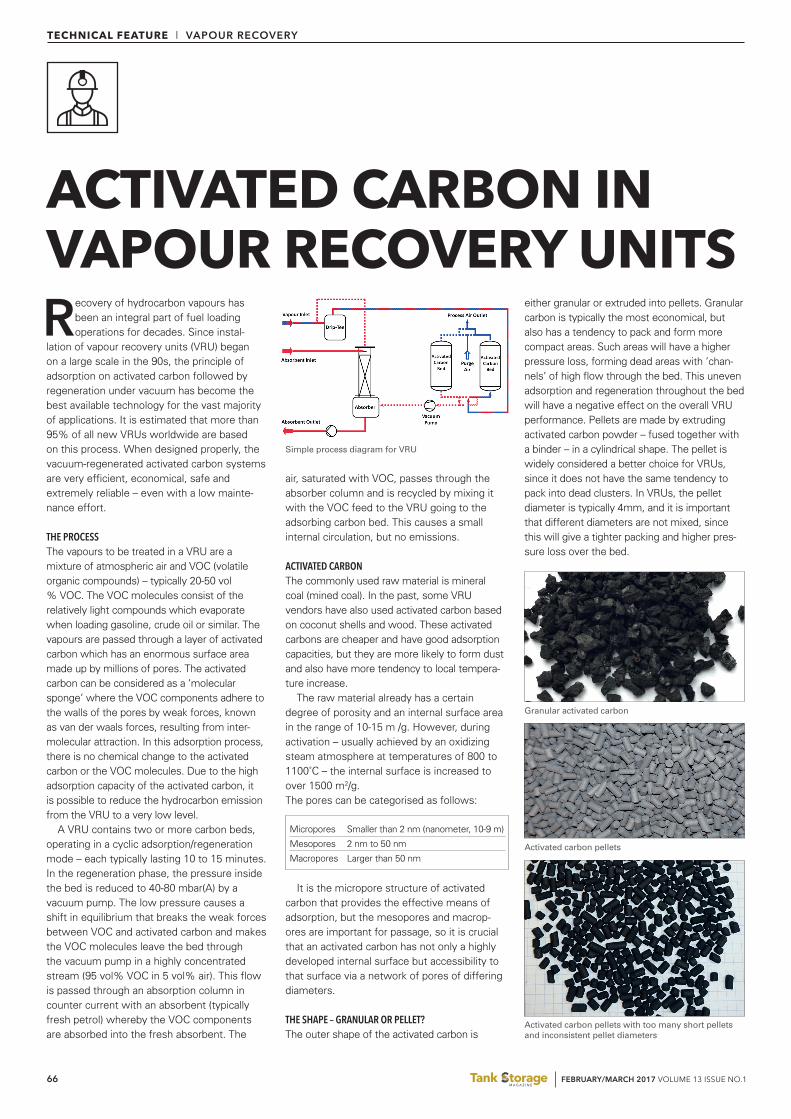
THE PROCESSThe vapours to be treated in a VRU are a mixture of atmospheric air and VOC (volatile organic compounds) – typically 20-50 vol % VOC. The VOC molecules consist of the relatively light compounds which evaporate when loading gasoline, crude oil or similar. The vapours are passed through a layer of activated carbon which has an enormous surface area made up by millions of pores. The activated carbon can be considered as a ‘molecular sponge’ where the VOC components adhere to the walls of the pores by weak forces, known as van der waals forces, resulting from inter-molecular attraction. In this adsorption process, there is no chemical change to the activated carbon or the VOC molecules. Due to the high adsorption capacity of the activated carbon, it is possible to reduce the hydrocarbon emission from the VRU to a very low level.
A VRU contains two or more carbon beds, operating in a cyclic adsorption/regeneration mode – each typically lasting 10 to 15 minutes. In the regeneration phase, the pressure inside the bed is reduced to 40-80 mbar(A) by a vacuum pump. The low pressure causes a shift in equilibrium that breaks the weak forces between VOC and activated carbon and makes the VOC molecules leave the bed through the vacuum pump in a highly concentrated stream (95 vol% VOC in 5 vol% air). This flow is passed through an absorption column in counter current with an absorbent (typically fresh petrol) whereby the VOC components are absorbed into the fresh absorbent. The
air, saturated with VOC, passes through the absorber column and is recycled by mixing it with the VOC feed to the VRU going to the adsorbing carbon bed. This causes a small internal circulation, but no emissions.
ACTIVATED CARBONThe commonly used raw material is mineral coal (mined coal). In the past, some VRU vendors have also used activated carbon based on coconut shells and wood. These activated carbons are cheaper and have good adsorption capacities, but they are more likely to form dust and also have more tendency to local tempera-ture increase.
The raw material already has a certain degree of porosity and an internal surface area in the range of 10-15 m²/g. However, during activation – usually achieved by an oxidizing steam atmosphere at temperatures of 800 to 1100˚C – the internal surface is increased to over 1500 m2/g.The pores can be categorised as follows:
It is the micropore structure of activated carbon that provides the effective means of adsorption, but the mesopores and macrop-ores are important for passage, so it is crucial that an activated carbon has not only a highly developed internal surface but accessibility to that surface via a network of pores of differing diameters.
THE SHAPE – GRANULAR OR PELLET?The outer shape of the activated carbon is
either granular or extruded into pellets. Granular carbon is typically the most economical, but also has a tendency to pack and form more compact areas. Such areas will have a higher pressure loss, forming dead areas with ‘chan-nels’ of high flow through the bed. This uneven adsorption and regeneration throughout the bed will have a negative effect on the overall VRU performance. Pellets are made by extruding activated carbon powder – fused together with a binder – in a cylindrical shape. The pellet is widely considered a better choice for VRUs, since it does not have the same tendency to pack into dead clusters. In VRUs, the pellet diameter is typically 4mm, and it is important that different diameters are not mixed, since this will give a tighter packing and higher pres-sure loss over the bed.
ACTIVATED CARBON IN VAPOUR RECOVERY UNITS
Micropores Smaller than 2 nm (nanometer, 10-9 m)
Mesopores 2 nm to 50 nm
Macropores Larger than 50 nm
Simple process diagram for VRU
Granular activated carbon
Activated carbon pellets
Activated carbon pellets with too many short pellets and inconsistent pellet diameters

FEBRUARY/MARCH 2017 VOLUME 13 ISSUE NO.1 FEBRUARY/MARCH 2017 VOLUME 13 ISSUE NO.1 67
TECHNICAL FEATURE l VAPOUR RECOVERY
CAPACITY & HEELThe adsorption capacity is the additional mass of VOC that can be adsorbed onto a specific mass of activated carbon. The capacity on virgin carbon is typically 30 wt%, meaning that 1 kg of carbon can adsorb 0,3 kg of VOC before it is fully saturated. In order to fully restore the carbon to the same capacity, a new re-activa-tion with 1000˚C steam would be required, and since this process is tough on the carbon, a considerable percentage would be lost into dust. This is not feasible in a cyclic system, which is why the much ‘softer’ vacuum-regen-eration is used instead. With regeneration by vacuum, the long-term capacity – also known as the ‘working capacity’ – is typically in the order of 8 wt% for a mineral based carbon. The difference between virgin capacity and working capacity is called the ‘heel.
HEAT OF ADSORPTIONThe adsorption process generates heat, and during the normal cyclic operation of the carbon beds the heat of adsorption will cause a temperature some 10 to 20˚C above the ambient temperature. Some hydrocarbons such as ketones and aldehydes are much more reactive and cause a higher heat development in the carbon. Some carbon (especially wood and coconut based) is more likely to cause a ‘temperature run-away’ or ‘hot spot’, which requires the VRU to be taken out of service, filled with inert gas and cooled down under careful supervision. When virgin activated carbon is exposed to vapours for the first time, it is extremely reactive and the heat generation is very significant. The temperature in the bed
will rise to around 100˚C and it is important that commissioning of virgin carbon in a VRU – also referred to as ‘pre-loading’ – is undertaken by a specialist.
One of the key words to avoid is ‘dust’ since dust will create pressure loss, reduce capacity by filling the surface pores and cause excessive wear in vacuum pumps and absor-bent pumps, block filters and settle in petrol storage tanks.
It is important that every batch of activated carbon is tested against the parameters that are crucial to the VRU operation – dust, dryness, density, pellet size, hardness and working capacity.
ENSURING OPTIMUM CONDITIONS FOR THE ACTIVATED CARBONIn a properly designed VRU, the lifetime of acti-vated carbon is typically 10-20 years, but if the VRU is not designed to ensure good operating conditions for the activated carbon, the lifetime can be as short as four to five years.
MOVEMENT INSIDE THE CARBON BEDIn the VRU, the pressure will shift between atmospheric and low vacuum at least four times every hour. In the beginning of the cycle, the vacuum pump pulls hard to get the pressure down to where desorption begins, and after the regeneration has finished the pressure must be rapidly equalised in order to get the bed back in-line for the adsorption cycle. Unless the carbon bed is held firmly in place, this constant pulling and pushing on the carbon will cause the carbon pieces to rub against each other and grind each other into dust. Obviously weak
carbon will be grinded down faster and granular carbon will pack more firmly into clusters, but even hard mineral based pellets will slowly lose mass into dust. Apart from ensuring that the acti-vated carbon is prevented from moving, a good VRU design also ensures that the forces acting on the carbon (the vacuum and the equalisation) are controlled and minimised.
Typically, the loss of carbon mass through dust is the single most important factor for lifetime of activated carbon – and it can be almost completely avoided with proper VRU design.
LONG-TERM ‘HEEL’As mentioned above, the ‘heel’ is the fraction of the initial adsorption capacity that cannot be restored by vacuum regeneration. It can be regarded as pores that are permanently occupied by VOC molecules that cannot be pulled off by vacuum. In any system, the heel will increase slowly over time, giving a slow decline in the working capacity. A decline in carbon capacity of a few percent per year should be expected, and a properly designed VRU will have some initial safety margin to compensate for this. In a good VRU mainte-nance plan, a carbon sample is also taken and analysed regularly in order to be able to pinpoint the most feasible time for carbon replacement well ahead.
Flooding of the carbon bedsFlooding of the activated carbon with liquid absorbent will cause irreversible damage and should be prevented by proper high level detec-tion in the vapour inlet and absorber column.
Carry-over of aerosols into the carbon bedsIt is crucial that the absorber column is fitted with a demister and that the flow through the vacuum pump and absorber column is con-trolled to avoid carry-over of aerosols into the carbon beds since this will cause irreversible damage to the carbon.
A WORD ON SAFETYTo some people, the use of activated carbon for vapour recovery still raises concerns. However, strict adherence to the above principles of VRU design and carbon selection has resulted in zero incidents over the past 20 years.
FOR MORE INFORMATIONThis article was written by Ben Barker, business development & sales manager for Cool Sorption. www.coolsorption.com
Selecting the best activated carbon for AVRUWhen selecting the ideal carbon for a VRU, the most important criteria are:
0
20
40
60
80
100
120
1 2 3 4 5 6 7 8 9 10 11 12 13 14 15 16 17 18 19 20
Loss of Activated Carbon capacity in a vacuum-regenerated VRU
Long-term "Heel"
Potential total loss of VRU capacity
Potential loss of carbon from grinding into dust
VRU capacity %
Years
What to aim for
An even flow distribution leads to the longest lifetime, lowest pressure loss and highest overall VRU capacity.
Low initial dust content
Strong, hard carbon will not break easily into dust and deteriorate, thus ensuring long lifetime of carbon
A working capacity high enough to ensure good long-term efficiency of VRU, but not too high since this will increase risk of ‘temperature run-away’
The required amount of carbon is always given by weight, but since density varies considerably, this plays an important part in the equation when sizing the carbon vessels
Carbon with a shape which has little tendency to pack into dense clusters
The higher the self-ignition temperature, the more safety margin against ‘temperature run-away’ inside the carbon beds.
Dense clusters are more likely to form hot-spots
Parameter
Flow distribution inside carbon bed
Dust
Mechanical strength (hardness)
Working capacity
Density
Low pressure loss
Safety / Self-ignition temperature
Best choice
Carbon pellets, 4mm diameter
Highly cleaned carbon with frequent batch sampling and testing
Mineral-based, high-quality carbon with well-defined hardness/ abrasion number
Mineral-based carbon with well-documented long-term working capacity
Working capacity must be related to density, and DRY density must be checked for each batch of carbon
Carbon pellets, 4mm diameter
Mineral-based carbon with a documented self-ignition temperature above 450°C
Carbon pellets over granular