Embed Size (px)
Citation preview

Specifications/Instructions
1
AB-7365
© 2016–2019 Azbil Corporation All Rights Reserved.
ACTIVALTM
Motorized Two-Way Valve with Flanged-End Connection<4-20 mA DC Input with 4-20 mA DC Feedback Output>
(PN16 / GG-20)
�OverviewACTIVALTM Model VY519_J is a series of motorized two-way valves with flanged-end connection. Rotary valve and actuator are integrated in a single unit.
Valve size ranges from DN15 (1/2”) to DN80 (3”), and valve body rating corresponds to ISO PN16.
Actuator has a reversible synchronous motor, which operates at a low voltage of 24 V AC.
4-20 mA DC input control signal provides proportional control in combination with a PLC (e.g., Model R35/R36).
* PLC: Programmable Logic Controller
�Features• Compact and lightweight:
Rotary motor actualizes small body and light weight.
• Valve and actuator integrated in a single unit: Pre-assembled body requires no adjustment.
• Valve for chilled/hot water control and for steam control applicable to high differential pressure, large Cv value, high rangeability, and low leakage.
• Durable actuator with low power consumption.
• Equal percentage flow characteristics.
• 4-20 mA DC output available for position feedback.
• Open/close changeover for input signal failure: Actuator fully opens/closes valve in case that the control signal is not input to the actuator. (Default: Fully open)
• Direction changeover of control action: Open/close action by 4-20 mA DC input signal is reversely controllable. Normal action 4 mA: 0 % to 20 mA: 100 % Reverse action 20 mA: 0 % to 4 mA: 100 %. (Default: Normal action)
• Adjustable dead band*: Dead band width can be narrowed to more precisely operate valve actuator.
* Actuator is not operated by input signal changed less than a certain amount. This amount of change is called dead band.
* Although our company name changed from Yamatake Corporation to Azbil Corporation on April 1, 2012, our former logo remains on this product.
2
AB-7365
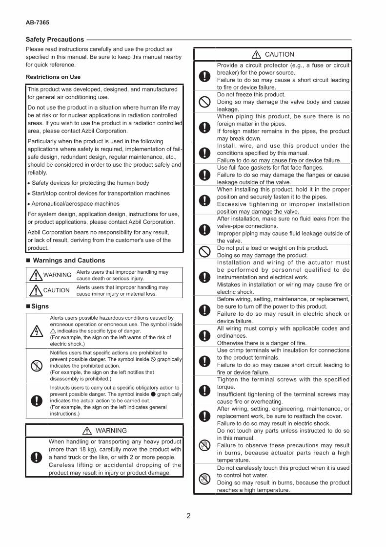
Safety PrecautionsPlease read instructions carefully and use the product as specified in this manual. Be sure to keep this manual nearby for quick reference.
Restrictions on Use
This product was developed, designed, and manufactured for general air conditioning use.
Do not use the product in a situation where human life may be at risk or for nuclear applications in radiation controlled areas. If you wish to use the product in a radiation controlled area, please contact Azbil Corporation.
Particularly when the product is used in the following applications where safety is required, implementation of fail-safe design, redundant design, regular maintenance, etc., should be considered in order to use the product safely and reliably.
• Safety devices for protecting the human body
• Start/stop control devices for transportation machines
• Aeronautical/aerospace machines
For system design, application design, instructions for use, or product applications, please contact Azbil Corporation.
Azbil Corporation bears no responsibility for any result, or lack of result, deriving from the customer's use of the product.
� Warnings and Cautions
WARNING Alerts users that improper handling may cause death or serious injury.
CAUTION Alerts users that improper handling may cause minor injury or material loss.
�Signs
Alerts users possible hazardous conditions caused by erroneous operation or erroneous use. The symbol inside indicates the specific type of danger. (For example, the sign on the left warns of the risk of electric shock.)
Notifies users that specific actions are prohibited to prevent possible danger. The symbol inside graphically indicates the prohibited action. (For example, the sign on the left notifies that disassembly is prohibited.)
Instructs users to carry out a specific obligatory action to prevent possible danger. The symbol inside graphically indicates the actual action to be carried out. (For example, the sign on the left indicates general instructions.)
WARNING
When handling or transporting any heavy product (more than 18 kg), carefully move the product with a hand truck or the like, or with 2 or more people. Careless lifting or accidental dropping of the product may result in injury or product damage.
CAUTION
Provide a circuit protector (e.g., a fuse or circuit breaker) for the power source. Failure to do so may cause a short circuit leading to fire or device failure.
Do not freeze this product. Doing so may damage the valve body and cause leakage.
When piping this product, be sure there is no foreign matter in the pipes.If foreign matter remains in the pipes, the product may break down.
Install, wire, and use this product under the conditions specified by this manual. Failure to do so may cause fire or device failure.
Use full face gaskets for flat face flanges. Failure to do so may damage the flanges or cause leakage outside of the valve.
When installing this product, hold it in the proper position and securely fasten it to the pipes.Excessive tightening or improper installation position may damage the valve.
After installation, make sure no fluid leaks from the valve-pipe connections.Improper piping may cause fluid leakage outside of the valve.
Do not put a load or weight on this product. Doing so may damage the product.
Installation and wiring of the actuator must be performed by personnel qual i f ied to do instrumentation and electrical work. Mistakes in installation or wiring may cause fire or electric shock.
Before wiring, setting, maintenance, or replacement, be sure to turn off the power to this product. Failure to do so may result in electric shock or device failure.
All wiring must comply with applicable codes and ordinances. Otherwise there is a danger of fire.
Use crimp terminals with insulation for connections to the product terminals. Failure to do so may cause short circuit leading to fire or device failure.
Tighten the terminal screws with the specified torque. Insufficient tightening of the terminal screws may cause fire or overheating.
After wiring, setting, engineering, maintenance, or replacement work, be sure to reattach the cover.Failure to do so may result in electric shock.
S
Do not touch any parts unless instructed to do so in this manual. Failure to observe these precautions may result in burns, because actuator parts reach a high temperature.
SDo not carelessly touch this product when it is used to control hot water. Doing so may result in burns, because the product reaches a high temperature.
3
AB-7365
IMPORTANT:• The service life of ACTIVAL operated with small dead band can be shortened since the ACTIVAL operates
more frequently with small dead band than with normal dead band.• Use shielded cable for the ACTIVAL with small dead band. Noise may affect the signal transmission causing
operation error, otherwise.• To control ACTIVAL with a third-party controller, please consult with Azbil Corporations’ sales personnel.
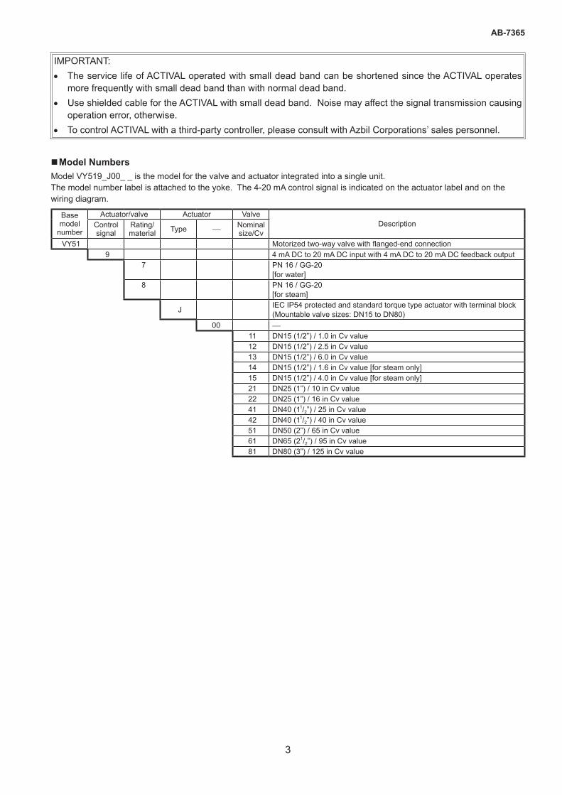
�Model NumbersModel VY519_J00_ _ is the model for the valve and actuator integrated into a single unit. The model number label is attached to the yoke. The 4-20 mA control signal is indicated on the actuator label and on the wiring diagram.
Base model
number
Actuator/valve Actuator ValveDescriptionControl
signalRating/ material Type Nominal
size/CvVY51 Motorized two-way valve with flanged-end connection
9 4 mA DC to 20 mA DC input with 4 mA DC to 20 mA DC feedback output7 PN 16 / GG-20
[for water]8 PN 16 / GG-20
[for steam]
J IEC IP54 protected and standard torque type actuator with terminal block (Mountable valve sizes: DN15 to DN80)
00 11 DN15 (1/2”) / 1.0 in Cv value12 DN15 (1/2”) / 2.5 in Cv value13 DN15 (1/2”) / 6.0 in Cv value14 DN15 (1/2”) / 1.6 in Cv value [for steam only]15 DN15 (1/2”) / 4.0 in Cv value [for steam only]21 DN25 (1”) / 10 in Cv value22 DN25 (1”) / 16 in Cv value41 DN40 (11/2”) / 25 in Cv value42 DN40 (11/2”) / 40 in Cv value51 DN50 (2”) / 65 in Cv value61 DN65 (21/2”) / 95 in Cv value81 DN80 (3”) / 125 in Cv value
4
AB-7365
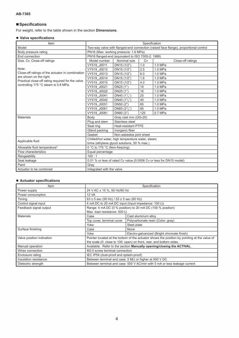
�SpecificationsFor weight, refer to the table shown in the section Dimensions.
z Valve specificationsItem Specification
Model Two-way valve with flanged-end connection (raised face flange), proportional controlBody pressure rating PN16 (Max. working pressure: 1.6 MPa)End connection PN16 flanged-end (equivalent to ISO 7005-2: 1988)Size, Cv, Close-off ratings
Note: Close-off ratings of the actuator in combination are shown on the right. Practical close-off rating required for the valve controlling 175 °C steam is 0.8 MPa.
Model number Nominal size Cv Close-off ratingsVY519_J0011 DN15 (1/2”) 1.0 1.0 MPaVY519_J0012 DN15 (1/2”) 2.5 1.0 MPaVY519_J0013 DN15 (1/2”) 6.0 1.0 MPaVY519_J0014 DN15 (1/2”) 1.6 1.0 MPaVY519_J0015 DN15 (1/2”) 4.0 1.0 MPaVY519_J0021 DN25 (1”) 10 1.0 MPaVY519_J0022 DN25 (1”) 16 1.0 MPaVY519_J0041 DN40 (11/2”) 25 1.0 MPaVY519_J0042 DN40 (11/2”) 40 1.0 MPaVY519_J0051 DN50 (2”) 65 1.0 MPaVY519_J0061 DN65 (21/2”) 95 1.0 MPaVY519_J0081 DN80 (3”) 125 0.7 MPa
Materials Body Gray cast iron (GG-20)Plug and stem Stainless steelSeat ring Heat-resistant PTFEGland packing Inorganic fiberGasket Non-asbestos joint sheet
Applicable fluid Chilled/hot water, high temperature water, steam, brine (ethylene glycol solutions, 50 % max.)
Allowable fluid temperature* 0 °C to 175 °C (Non-freezing) Flow characteristics Equal percentageRangeability 100 : 1Seat leakage 0.01 % or less of rated Cv value (0.0006 Cv or less for DN15 model)Paint GrayActuator to be combined Integrated with the valve
z Actuator specificationsItem Specification
Power supply 24 V AC ± 15 %, 50 Hz/60 HzPower consumption 12 VATiming 63 ± 5 sec (50 Hz) / 53 ± 5 sec (60 Hz)Control signal input 4 mA DC to 20 mA DC input (Input impedance: 100 W)Feedback signal output Range: 4 mA DC (0 % position) to 20 mA DC (100 % position)
Max. load resistance: 500 WMaterials Case Cast aluminum alloy
Top cover, terminal cover Polycarbonate resin (Color: gray)Yoke Steel plate
Surface finishing Case NoneYoke Electro-galvanized (Bright chromate finish)
Valve position indication Pointer located at the bottom of the actuator shows the position by pointing at the value of the scale (0: close to 100: open) on front, rear, and bottom sides.
Manual operation Available. Refer to the section Manually opening/closing the ACTIVAL.Wires connection M3.5 screw terminal connectionEnclosure rating IEC IP54 (dust-proof and splash-proof)Insulation resistance Between terminal and case: 5 MW or higher at 500 V DCDielectric strength Between terminal and case: 500 V AC/min with 5 mA or less leakage current
5
AB-7365
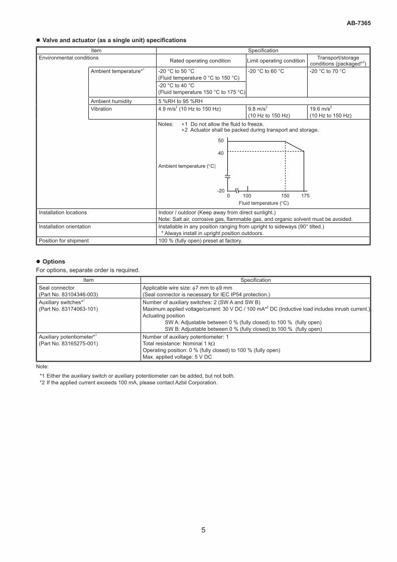
z Valve and actuator (as a single unit) specificationsItem Specification
Environmental conditions Rated operating condition Limit operating condition Transport/storage conditions (packaged*2)
Ambient temperature*1 -20 °C to 50 °C(Fluid temperature 0 °C to 150 °C)
-20 °C to 60 °C -20 °C to 70 °C
-20 °C to 40 °C(Fluid temperature 150 °C to 175 °C)
Ambient humidity 5 %RH to 95 %RHVibration 4.9 m/s2 (10 Hz to 150 Hz) 9.8 m/s2
(10 Hz to 150 Hz)19.6 m/s2
(10 Hz to 150 Hz)Notes: *1 Do not allow the fluid to freeze. *2 Actuator shall be packed during transport and storage.
Installation locations Indoor / outdoor (Keep away from direct sunlight.)Note: Salt air, corrosive gas, flammable gas, and organic solvent must be avoided.
Installation orientation Installable in any position ranging from upright to sideways (90° tilted.) * Always install in upright position outdoors.
Position for shipment 100 % (fully open) preset at factory.
z OptionsFor options, separate order is required.
Item SpecificationSeal connector (Part No. 83104346-003)
Applicable wire size: f7 mm to f9 mm(Seal connector is necessary for IEC IP54 protection.)
Auxiliary switches*1 (Part No. 83174063-101)
Number of auxiliary switches: 2 (SW A and SW B)Maximum applied voltage/current: 30 V DC / 100 mA*2 DC (Inductive load includes inrush current.)Actuating position SW A: Adjustable between 0 % (fully closed) to 100 % (fully open) SW B: Adjustable between 0 % (fully closed) to 100 % (fully open)
Auxiliary potentiometer*1 (Part No. 83165275-001)
Number of auxiliary potentiometer: 1Total resistance: Nominal 1 kWOperating position: 0 % (fully closed) to 100 % (fully open)Max. applied voltage: 5 V DC
Note:
*1 Either the auxiliary switch or auxiliary potentiometer can be added, but not both. *2 If the applied current exceeds 100 mA, please contact Azbil Corporation.
Ambient temperature (°C)
50
40
-20 100 175 150 0
Fluid temperature (°C)
6
AB-7365
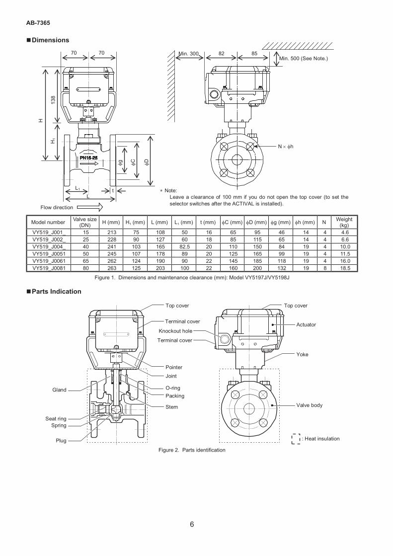
�Dimensions
Model number Valve size (DN) H (mm) H1 (mm) L (mm) L1 (mm) t (mm) fC (mm) fD (mm) fg (mm) fh (mm) N Weight
(kg)VY519_J001_ 15 213 75 108 50 16 65 95 46 14 4 4.6VY519_J002_ 25 228 90 127 60 18 85 115 65 14 4 6.6VY519_J004_ 40 241 103 165 82.5 20 110 150 84 19 4 10.0VY519_J0051 50 245 107 178 89 20 125 165 99 19 4 11.5VY519_J0061 65 262 124 190 90 22 145 185 118 19 4 16.0VY519_J0081 80 263 125 203 100 22 160 200 132 19 8 18.5
Figure 1. Dimensions and maintenance clearance (mm): Model VY5197J/VY5198J
�Parts Indication
Figure 2. Parts identification
∗ Note: Leave a clearance of 100 mm if you do not open the top cover (to set the selector switches after the ACTIVAL is installed).
70 70
H
H1
138
L1 L
t
φg
φC
φD
82 85 Min. 500 (See Note.)
Min. 300
N × φh
138
Flow direction
Top cover
Terminal cover
Top cover
Knockout hole Terminal cover
Yoke
Actuator
Valve body
Pointer
Joint
O-ring Packing
Stem
Seat ring Spring
Plug : Heat insulation
Gland
7
AB-7365
�SettingOn the PCB (printed circuit board) of the actuator, the selector switches are provided.
CAUTION
Before beginning setup work, be sure to turn off the power to this product. Failure to do so may result in electric shock or device failure.
After setup work, be sure to reattach the cover. Failure to do so may result in electric shock.
SDo not touch any parts unless instructed to do so in this manual. Failure to observe these precautions may result in burns, because actuator parts reach a high temperature.
IMPORTANT:• Set the selector switches using a pen nib or a finger. Do not use a tool such as a screwdriver. Such a tool
can damage the selector switches or the PCB.• The service life of ACTIVAL operated with small dead band can be shortened since the ACTIVAL operates
more frequently with small dead band than with normal dead band.• To operate the product with small dead band, provide shielded cable for input/output signal lines and power
line. Unshielded cable can cause error due to noise.
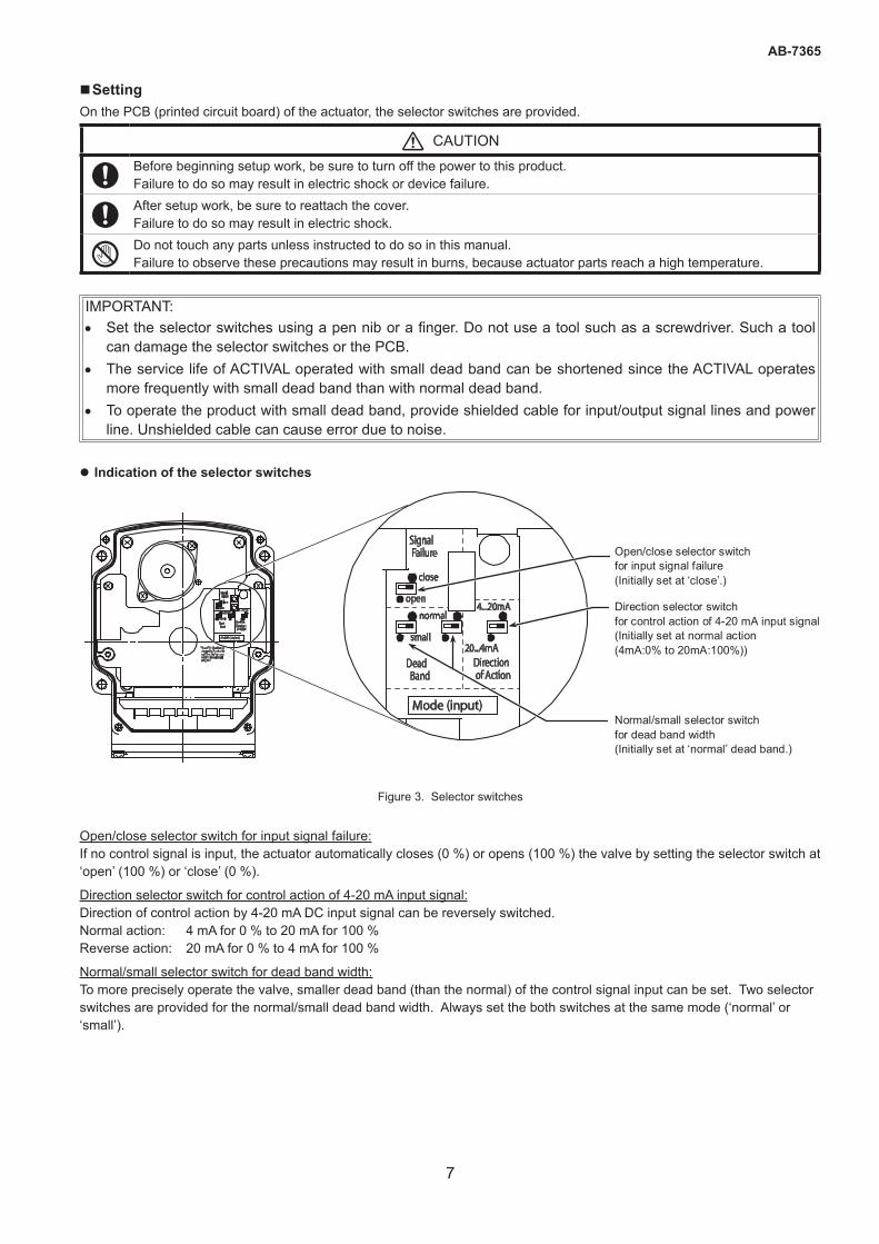
z Indication of the selector switches
Open/close selector switch for input signal failure (Initially set at ‘close’.) Direction selector switch for control action of 4-20 mA input signal (Initially set at normal action (4mA:0% to 20mA:100%)) Normal/small selector switch for dead band width (Initially set at ‘normal’ dead band.)
Figure 3. Selector switches
Open/close selector switch for input signal failure:If no control signal is input, the actuator automatically closes (0 %) or opens (100 %) the valve by setting the selector switch at ‘open’ (100 %) or ‘close’ (0 %).
Direction selector switch for control action of 4-20 mA input signal:Direction of control action by 4-20 mA DC input signal can be reversely switched. Normal action: 4 mA for 0 % to 20 mA for 100 % Reverse action: 20 mA for 0 % to 4 mA for 100 %
Normal/small selector switch for dead band width:To more precisely operate the valve, smaller dead band (than the normal) of the control signal input can be set. Two selector switches are provided for the normal/small dead band width. Always set the both switches at the same mode (‘normal’ or ‘small’).
8
AB-7365
� InstallationPrecautions for installation
WARNING
When handling or transporting any heavy product (more than 18 kg), carefully move the product with a hand truck or the like, or with 2 or more people. Careless lifting or accidental dropping of the product may result in injury or product damage.
CAUTION
Do not freeze this product. Doing so may damage the valve body and cause leakage.
When piping this product, be sure there is no foreign matter in the pipes.If foreign matter remains in the pipes, the product may break down.
Install, wire, and use this product under the conditions specifi ed by this manual. Failure to do so may cause fi re or device failure.
Use full face gaskets for fl at face fl anges. Failure to do so may damage the fl anges or cause leakage outside of the valve.
Installation and wiring of the actuator must be performed by personnel qualifi ed to do instrumentation and electrical work. Mistakes in installation or wiring may cause fi re or electric shock.
• ACTIVAL Model VY519_J is the valve and actuator integrated into a single unit. Do not combine the valve with any other actuator, or do not combine the actuator with any other valve.
• To remove foreign substances inside the pipes, install a strainer with 40 or more meshes (with 80 or more meshes recommended for steam control) on the infl ow side of each valve. In case that the strainers cannot be installed on the infl ow side of each valve, install it on the pipe diverting sections (sections diverting from main piping system to sub piping system).
• Install the valve so that the fl ow direction of process fl uid agrees with the arrow indicated on the valve body.
z Installation location
IMPORTANT:• The top and the terminal covers might be corroded by chemicals and organic solvent or their vapor. Do not
expose the ACTIVAL to such substances/vapor.• When the ACTIVAL is used for steam humidifying, install a valve interlocking with air-conditioning unit on the
infl ow side in case the ACTIVAL gets damaged.• Although the ACTIVAL can be used in high humidity environments (max. 95 %RH), do not immerse the
actuator in water.• Although the ACTIVAL can be used outdoors, be sure not to expose the ACTIVAL to direct sunlight.
• Install the ACTIVAL in a position allowing easy access for maintenance and inspection. Fig. 1 shows the minimum clearance for maintenance and inspection. When installing the ACTIVAL in a ceiling space, provide an access hole within the 50 cm radius of the ACTIVAL. And, place a drain pan under the valve.
• Do not install the product nearby a steam coil or a hot-water (in high temperature) coil. High heat radiation may result in an actuator malfunction.
• Do not mount the ACTIVAL on a pipe where water hammer occurs, or where solid objects including slug may accumulate.• To set the selector switches after installation, leave a enough clearance above the top cover of the actuator, as shown in
Fig. 1.
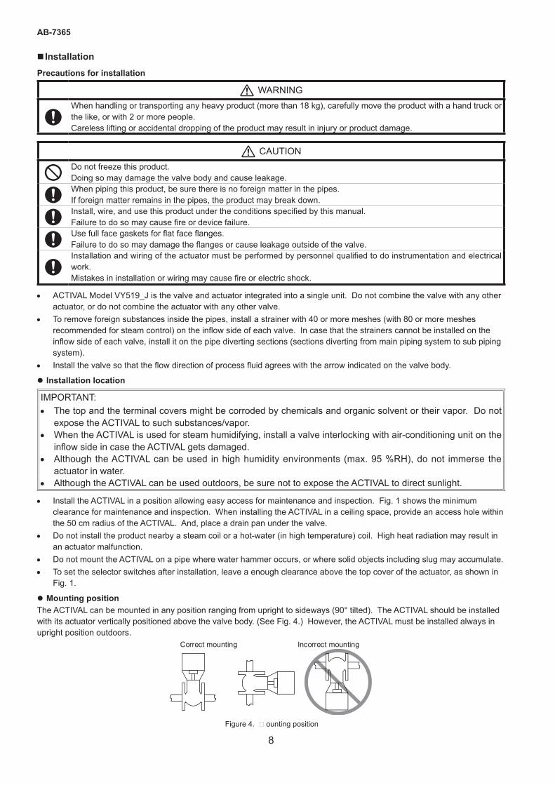
z Mounting positionThe ACTIVAL can be mounted in any position ranging from upright to sideways (90° tilted). The ACTIVAL should be installed with its actuator vertically positioned above the valve body. (See Fig. 4.) However, the ACTIVAL must be installed always in upright position outdoors.
Correct mounting Incorrect mounting
Figure 4. Mounting position
9
AB-7365
z Piping
CAUTION
When installing this product, hold it in the proper position and securely fasten it to the pipes.Excessive tightening or improper installation position may damage the valve.
• Check that the model number of the product is what you ordered. The model number is shown on the label attached to the yoke.
• Install a bypass pipe and gate valves on the inflow, outflow, and bypass sides. Also, install a strainer with 40 or more meshes (with 80 or more meshes recommended for steam control) on the inflow side.
• When installing the ACTIVAL to the pipes, do not allow any object, such as chips, to get inside a pipe or valve. Valve cannot fully close, or the valve seat may get damaged causing fluid leakage, due to an object jammed inside the valve.
• When piping, do not apply too much sealing material, such as solidifying liquid and tape, to the pipe connection sections so that these materials flow into the valve. Valve cannot fully closes, or the valve seat may get damaged causing fluid leakage, due to the sealing material jammed inside the valve.
• Before activating the ACTIVAL, fully open (in 100 % position) the valve and flush the pipes (with the ACTIVAL installed) at the maximum flow rate to remove all the foreign substances. (Factory preset position: 100 %)
• For steam control, drain retained water (condensate) in piping. Install a trap on a pipe run which may retain condensate. Condensate may cause water hummer or damage the valve and piping.
CAUTION
After installation, make sure no fluid leaks from the valve-pipe connections.Improper piping may cause fluid leakage outside of the valve.
Do not put a load or weight on this product. Doing so may damage the product.
z Heat insulationDo not apply heat insulation to the actuator or to the yoke, as shows in Fig. 2. If the yoke and the actuator are covered with insulation material, the pointer cannot be checked and may be distorted.
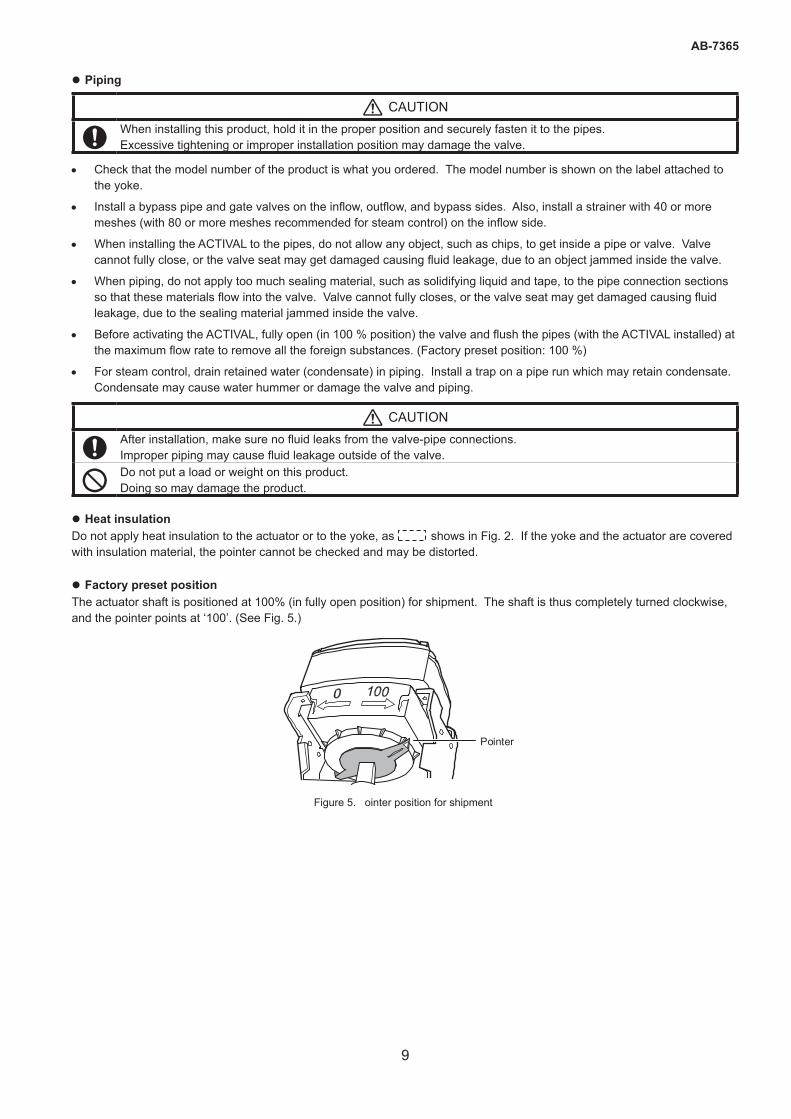
z Factory preset positionThe actuator shaft is positioned at 100% (in fully open position) for shipment. The shaft is thus completely turned clockwise, and the pointer points at ‘100’. (See Fig. 5.)
Pointer
Figure 5. Pointer position for shipment
10
AB-7365
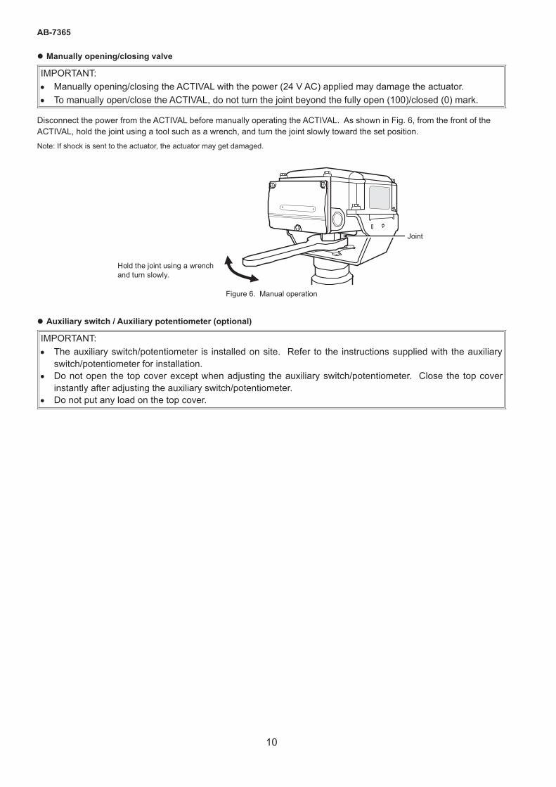
z Manually opening/closing valve
IMPORTANT:• Manually opening/closing the ACTIVAL with the power (24 V AC) applied may damage the actuator.• To manually open/close the ACTIVAL, do not turn the joint beyond the fully open (100)/closed (0) mark.
Disconnect the power from the ACTIVAL before manually operating the ACTIVAL. As shown in Fig. 6, from the front of the ACTIVAL, hold the joint using a tool such as a wrench, and turn the joint slowly toward the set position. Note: If shock is sent to the actuator, the actuator may get damaged.
Joint
Hold the joint using a wrench and turn slowly.
Figure 6. Manual operation
z Auxiliary switch / Auxiliary potentiometer (optional)
IMPORTANT:• The auxiliary switch/potentiometer is installed on site. Refer to the instructions supplied with the auxiliary
switch/potentiometer for installation.• Do not open the top cover except when adjusting the auxiliary switch/potentiometer. Close the top cover
instantly after adjusting the auxiliary switch/potentiometer.• Do not put any load on the top cover.
11
AB-7365
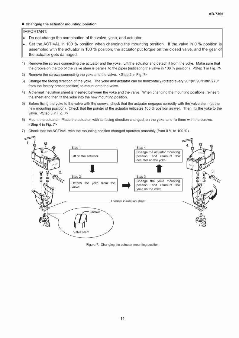
z Changing the actuator mounting position
IMPORTANT:• Do not change the combination of the valve, yoke, and actuator.• Set the ACTIVAL in 100 % position when changing the mounting position. If the valve in 0 % position is
assembled with the actuator in 100 % position, the actuator put torque on the closed valve, and the gear of the actuator gets damaged.
1) Remove the screws connecting the actuator and the yoke. Lift the actuator and detach it from the yoke. Make sure that the groove on the top of the valve stem is parallel to the pipes (indicating the valve in 100 % position). <Step 1 in Fig. 7>
2) Remove the screws connecting the yoke and the valve. <Step 2 in Fig. 7>
3) Change the facing direction of the yoke. The yoke and actuator can be horizontally rotated every 90° (0°/90°/180°/270° from the factory preset position) to mount onto the valve.
4) A thermal insulation sheet is inserted between the yoke and the valve. When changing the mounting positions, reinsert the sheet and then fit the yoke into the new mounting position.
5) Before fixing the yoke to the valve with the screws, check that the actuator engages correctly with the valve stem (at the new mounting position). Check that the pointer of the actuator indicates 100 % position as well. Then, fix the yoke to the valve. <Step 3 in Fig. 7>
6) Mount the actuator. Place the actuator, with its facing direction changed, on the yoke, and fix them with the screws. <Step 4 in Fig. 7>
7) Check that the ACTIVAL with the mounting position changed operates smoothly (from 0 % to 100 %).
Step 1 Step 4
Lift off the actuator. Change the actuator mounting position, and remount the actuator on the yoke.
Step 2 Step 3
Detach the yoke from the valve.
Change the yoke mounting position, and remount the yoke on the valve.
Groove
Valve stem
Thermal insulation sheet
Figure 7. Changing the actuator mounting position
12
AB-7365
�Wiring
CAUTION
Provide a circuit protector (e.g., a fuse or circuit breaker) for the power source. Failure to do so may cause a short circuit leading to fire or device failure.
Install, wire, and use this product under the conditions specified by this manual. Failure to do so may cause fire or device failure.
Installation and wiring of the actuator must be performed by personnel qualified to do instrumentation and electrical work. Mistakes in installation or wiring may cause fire or electric shock.
Before wiring, be sure to turn off the power to this product. Failure to do so may result in electric shock or device failure.
All wiring must comply with applicable codes and ordinances. Otherwise there is a danger of fire.
Use crimp terminals with insulation for connections to the product terminals. Failure to do so may cause short circuit leading to fire or device failure.
Tighten the terminal screws with the specified torque. Insufficient tightening of the terminal screws may cause fire or overheating.
IMPORTANT:• The ACTIVAL is designed for 24 V AC power supply voltage.
Do not apply any other power voltage (e.g., 100 V AC, 200 V AC) to the ACTIVAL.• Make sure the polarity of the power supply and 4-20 mA DC feedback output referring to the wiring diagrams.
Incorrect wiring may result in PCB (print circuit board) burnout.• Do not connect 24 V AC power to the terminals 4 to 7.
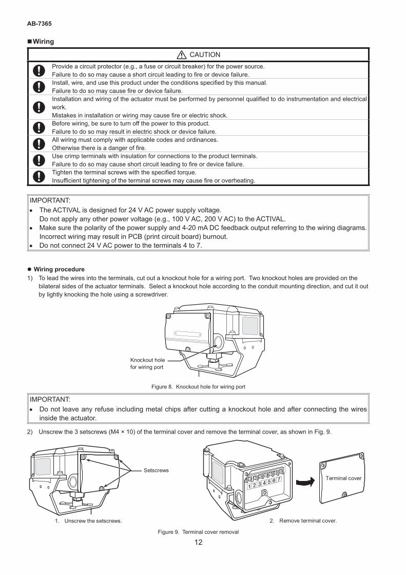
z Wiring procedure1) To lead the wires into the terminals, cut out a knockout hole for a wiring port. Two knockout holes are provided on the
bilateral sides of the actuator terminals. Select a knockout hole according to the conduit mounting direction, and cut it out by lightly knocking the hole using a screwdriver.
Knockout hole for wiring port
Figure 8. Knockout hole for wiring port
IMPORTANT:• Do not leave any refuse including metal chips after cutting a knockout hole and after connecting the wires
inside the actuator.
2) Unscrew the 3 setscrews (M4 × 10) of the terminal cover and remove the terminal cover, as shown in Fig. 9.
1. Unscrew the setscrews. 2. Remove terminal cover.
Terminal cover Setscrews
Figure 9. Terminal cover removal
13
AB-7365
3) Correctly connect the wires to the terminals with M3.5 screw terminal lugs, referring to Figs 10 to 12.
4) When the ACTIVAL is used in a high-humidity environment or outdoors, use a water-proof connector for the wiring port.
CAUTION
After wiring, be sure to reattach the cover. Failure to do so may result in electric shock.
z To keep IP54 protection (dust-proof and splash-proof),Use a water-proof connector for the ACTIVAL in a high-humidity environment or outdoor location.
• Be sure to completely close the terminal cover and the top cover.
• Waterproof the wiring port. - For cable connection, use a water-proof connector. (Seal connector Part No. 83104346-003 is recommended.)
- For conduit connection, use a water-proof plica tube or the like.
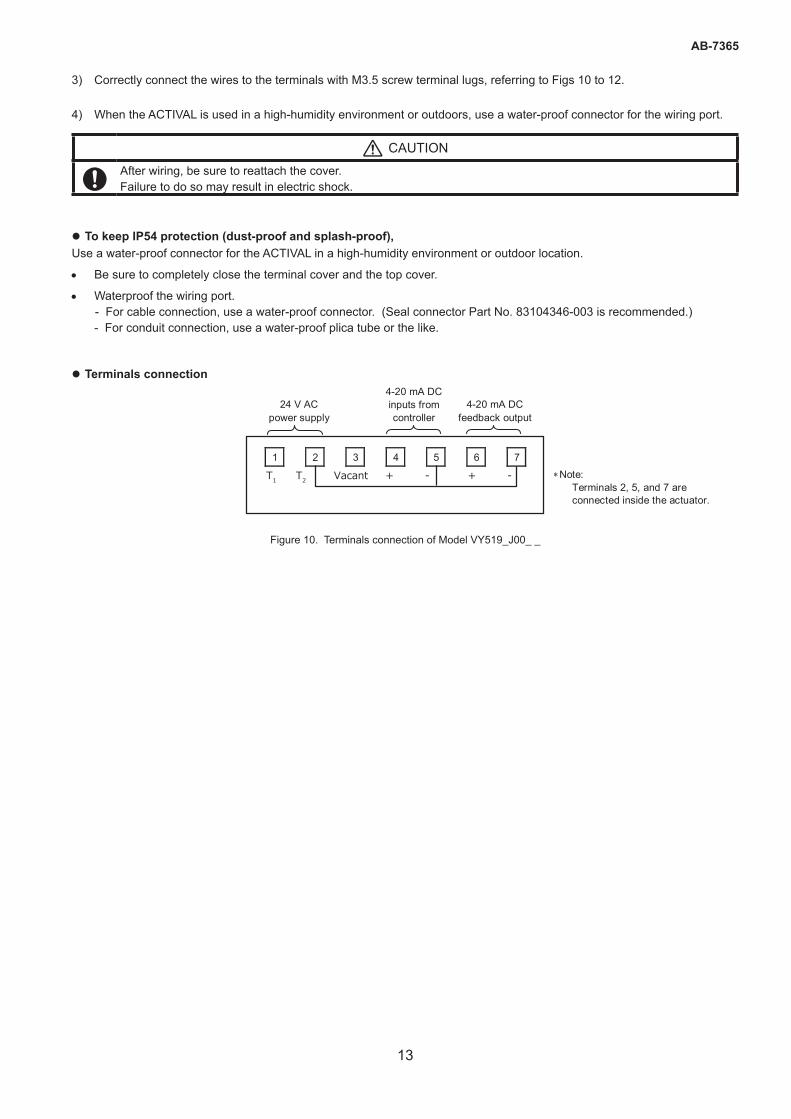
z Terminals connection
1 2 3 4 5 6 7
24 V AC power supply
4-20 mA DC inputs from controller
4-20 mA DC feedback output
∗Note: Terminals 2, 5, and 7 are connected inside the actuator.
T1 T2 Vacant + - + -
Figure 10. Terminals connection of Model VY519_J00_ _
14
AB-7365
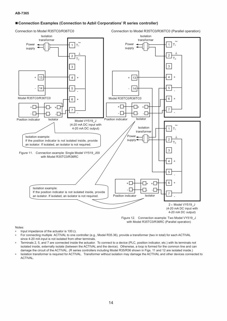
�Connection Examples (Connection to Azbil Corporations’ R series controller)
Connection to Model R35TC0/R36TC0 Connection to Model R35TC0/R36TC0 (Parallel operation)
Notes:* Input impedance of the actuator is 100 W.* For connecting multiple ACTIVAL to one controller (e.g., Model R35.36), provide a transformer (two in total) for each ACTIVAL
since 4-20 mA input is not isolated from other terminals.* Terminals 2, 5, and 7 are connected inside the actuator. To connect to a device (PLC, position indicator, etc.) with its terminals not
isolated inside, externally isolate (between the ACTIVAL and the device). Otherwise, a loop is formed for the common line and can damage the circuit of the ACTIVAL. (R series controllers including Model R35/R36 shown in Figs. 11 and 12 are isolated inside.)
* Isolation transformer is required for ACTIVAL. Transformer without isolation may damage the ACTIVAL and other devices connected to ACTIVAL.
Model R35TC0/R36TC0
+ 13
- 14
1 T1
2T2
4 +
3
5-
6 +
7-
Figure 12. Connection example: Two Model VY519_J with Model R35TC0/R36RC (Parallel operation)
2 × Model VY519_J(4-20 mA DC input with
4-20 mA DC output)
1 T1
2T2
4 +
3
5-
6 +
7-
Power supply
Isolationtransformer
Power supply
Isolationtransformer
Position indicator Isolator
+
-
+ +
- -
Position indicator Isolator
+
-
+ +
- -
Isolation example:If the position indicator is not isolated inside, provide an isolator. If isolated, an isolator is not required.
Model R35TC0/R36TC0
Model VY519_J(4-20 mA DC input with
4-20 mA DC output)
+ 13
- 14
1 T1
2T2
4 +
3
5-
6 +
7-
Figure 11. Connection example: Single Model VY519_J00with Model R35TC0/R36RC
Power supply
Isolationtransformer
Position indicator Isolator
+
-
+ +
- -
Isolation example:If the position indicator is not isolated inside, provide an isolator. If isolated, an isolator is not required.
15
AB-7365
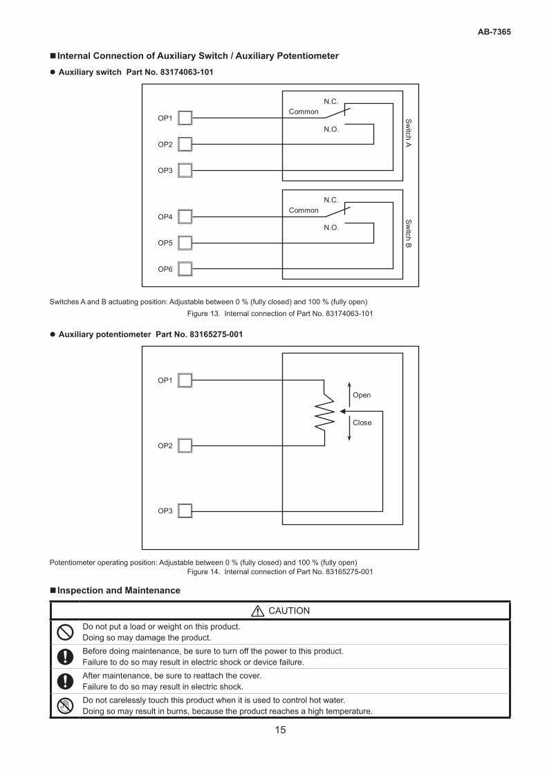
� Internal Connection of Auxiliary Switch / Auxiliary Potentiometer z Auxiliary switch Part No. 83174063-101
OP1
OP2
OP3
N.C. N.O.
Common
OP4
OP5
OP6
N.C. N.O.
Common
Sw
itch A
Sw
itch B
Switches A and B actuating position: Adjustable between 0 % (fully closed) and 100 % (fully open)Figure 13. Internal connection of Part No. 83174063-101
z Auxiliary potentiometer Part No. 83165275-001
OP1
OP2
OP3
Open Close
Potentiometer operating position: Adjustable between 0 % (fully closed) and 100 % (fully open)Figure 14. Internal connection of Part No. 83165275-001
� Inspection and Maintenance
CAUTION
Do not put a load or weight on this product. Doing so may damage the product.
Before doing maintenance, be sure to turn off the power to this product. Failure to do so may result in electric shock or device failure.
After maintenance, be sure to reattach the cover. Failure to do so may result in electric shock.
SDo not carelessly touch this product when it is used to control hot water. Doing so may result in burns, because the product reaches a high temperature.
Specifications are subject to change without notice.
https://www.azbil.com/
1-12-2 Kawana, Fujisawa, Kanagawa251-8522 JAPAN
Building Systems Company
16
AB-7365Rev. 2.0 Dec. 2019
AB-7365
ACTIVAL is a trademark of Azbil Corporation in Japan or in other countries.
This product complies with the following harmonised standards of the Electromagnetic Compatibility Directive (EMCD) and the Restriction of the use of certain Hazardous Substances in Electrical and Electronic Equipment Directive (RoHSD) .
EMCD: EN61000-6-2 EN55011 Class A, Group 1
RoHSD: EN50581
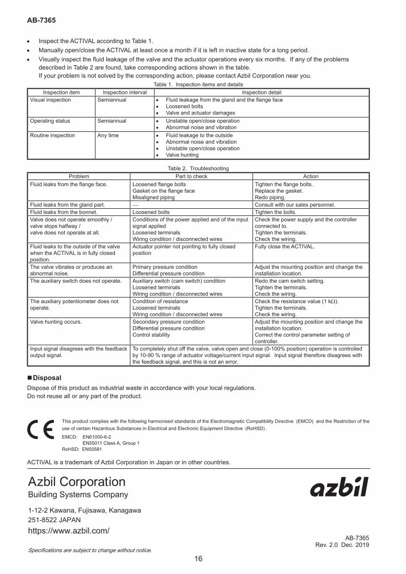
• Inspect the ACTIVAL according to Table 1.• Manually open/close the ACTIVAL at least once a month if it is left in inactive state for a long period.• Visually inspect the fluid leakage of the valve and the actuator operations every six months. If any of the problems
described in Table 2 are found, take corresponding actions shown in the table. If your problem is not solved by the corresponding action, please contact Azbil Corporation near you.
Table 1. Inspection items and detailsInspection item Inspection interval Inspection detail
Visual inspection Semiannual • Fluid leakage from the gland and the flange face• Loosened bolts• Valve and actuator damages
Operating status Semiannual • Unstable open/close operation• Abnormal noise and vibration
Routine inspection Any time • Fluid leakage to the outside• Abnormal noise and vibration• Unstable open/close operation• Valve hunting
Table 2. TroubleshootingProblem Part to check Action
Fluid leaks from the flange face. Loosened flange boltsGasket on the flange faceMisaligned piping
Tighten the flange bolts.Replace the gasket.Redo piping.
Fluid leaks from the gland part. Consult with our sales personnel.Fluid leaks from the bonnet. Loosened bolts Tighten the bolts.Valve does not operate smoothly / valve stops halfway / valve does not operate at all.
Conditions of the power applied and of the input signal appliedLoosened terminalsWiring condition / disconnected wires
Check the power supply and the controller connected to.Tighten the terminals.Check the wiring.
Fluid leaks to the outside of the valve when the ACTIVAL is in fully closed position.
Actuator pointer not pointing to fully closed position
Fully close the ACTIVAL.
The valve vibrates or produces an abnormal noise.
Primary pressure conditionDifferential pressure condition
Adjust the mounting position and change the installation location.
The auxiliary switch does not operate. Auxiliary switch (cam switch) conditionLoosened terminalsWiring condition / disconnected wires
Redo the cam switch setting.Tighten the terminals.Check the wiring.
The auxiliary potentiometer does not operate.
Condition of resistanceLoosened terminalsWiring condition / disconnected wires
Check the resistance value (1 kW).Tighten the terminals.Check the wiring.
Valve hunting occurs. Secondary pressure conditionDifferential pressure conditionControl stability
Adjust the mounting position and change the installation location.Correct the control parameter setting of controller.
Input signal disagrees with the feedback output signal.
To completely shut off the valve, valve open and close (0-100% position) operation is controlled by 10-90 % range of actuator voltage/current input signal. Input signal therefore disagrees with the feedback signal, and this is not an error.
�DisposalDispose of this product as industrial waste in accordance with your local regulations. Do not reuse all or any part of the product.