Embed Size (px)
DESCRIPTION
Â
Citation preview
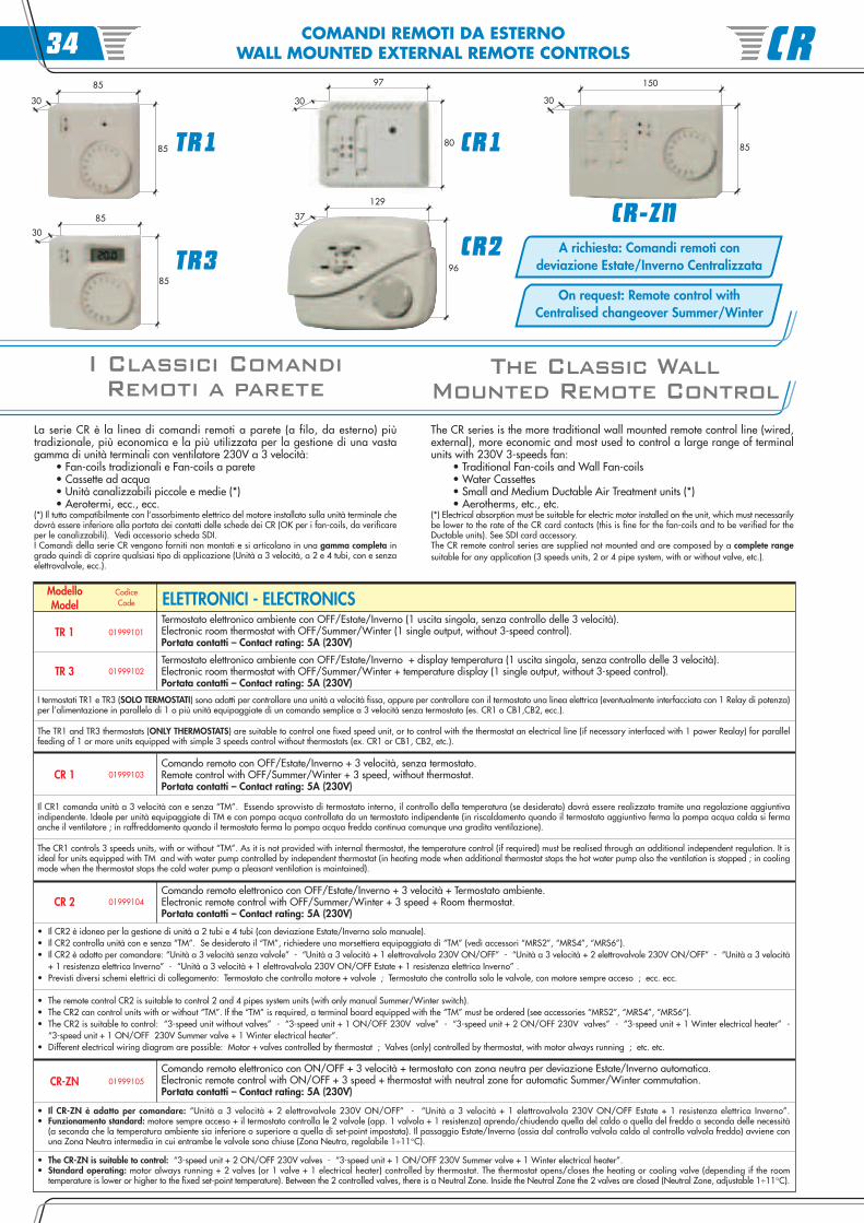
COMANDI REMOTI DA ESTERNOWALL MOUNTED EXTERNAL REMOTE CONTROLS
A richiesta: Comandi remoti condeviazione Estate/Inverno Centralizzata
On request: Remote control withCentralised changeover Summer/Winter
La serie CR è la linea di comandi remoti a parete (a filo, da esterno) piùtradizionale, più economica e la più utilizzata per la gestione di una vastagamma di unità terminali con ventilatore 230V a 3 velocità:
• Fan-coils tradizionali e Fan-coils a parete • Cassette ad acqua • Unità canalizzabili piccole e medie (*) • Aerotermi, ecc., ecc.
(*) Il tutto compatibilmente con l’assorbimento elettrico del motore installato sulla unità terminale chedovrà essere inferiore alla portata dei contatti delle schede dei CR (OK per i fan-coils, da verificareper le canalizzabili). Vedi accessorio scheda SDI.I Comandi della serie CR vengono forniti non montati e si articolano in una gamma completa ingrado quindi di coprire qualsiasi tipo di applicazione (Unità a 3 velocità, a 2 e 4 tubi, con e senzaelettrovalvole, ecc.).
I Classici ComandiRemoti a parete
The Classic WallMounted Remote Control
The CR series is the more traditional wall mounted remote control line (wired,external), more economic and most used to control a large range of terminalunits with 230V 3-speeds fan:
• Traditional Fan-coils and Wall Fan-coils • Water Cassettes • Small and Medium Ductable Air Treatment units (*) • Aerotherms, etc., etc.
(*) Electrical absorption must be suitable for electric motor installed on the unit, which must necessarilybe lower to the rate of the CR card contacts (this is fine for the fan-coils and to be verified for theDuctable units). See SDI card accessory.The CR remote control series are supplied not mounted and are composed by a complete rangesuitable for any application (3 speeds units, 2 or 4 pipe system, with or without valve, etc.).
ModelloModel
CodiceCode
CR 1 01999103
Termostato elettronico ambiente con OFF/Estate/Inverno (1 uscita singola, senza controllo delle 3 velocità).Electronic room thermostat with OFF/Summer/Winter (1 single output, without 3-speed control).Portata contatti – Contact rating: 5A (230V)
TR 1 01999101
ELETTRONICI - ELECTRONICS
TR 3 01999102
CR 2 01999104
• Il CR2 è idoneo per la gestione di unità a 2 tubi e 4 tubi (con deviazione Estate/Inverno solo manuale).• Il CR2 controlla unità con e senza “TM”. Se desiderato il “TM”, richiedere una morsettiera equipaggiata di “TM” (vedi accessori “MRS2”, “MRS4”, “MRS6”).• Il CR2 è adatto per comandare: “Unità a 3 velocità senza valvole” - “Unità a 3 velocità + 1 elettrovalvola 230V ON/OFF” - “Unità a 3 velocità + 2 elettrovalvole 230V ON/OFF” - “Unità a 3 velocità
+ 1 resistenza elettrica Inverno” - “Unità a 3 velocità + 1 elettrovalvola 230V ON/OFF Estate + 1 resistenza elettrica Inverno” .• Previsti diversi schemi elettrici di collegamento: Termostato che controlla motore + valvole ; Termostato che controlla solo le valvole, con motore sempre acceso ; ecc. ecc.
Termostato elettronico ambiente con OFF/Estate/Inverno + display temperatura (1 uscita singola, senza controllo delle 3 velocità).Electronic room thermostat with OFF/Summer/Winter + temperature display (1 single output, without 3-speed control).Portata contatti – Contact rating: 5A (230V)
I termostati TR1 e TR3 (SOLO TERMOSTATI) sono adatti per controllare una unità a velocità fissa, oppure per controllare con il termostato una linea elettrica (eventualmente interfacciata con 1 Relay di potenza)per l’alimentazione in parallelo di 1 o più unità equipaggiate di un comando semplice a 3 velocità senza termostato (es. CR1 o CB1,CB2, ecc.).
The TR1 and TR3 thermostats (ONLY THERMOSTATS) are suitable to control one fixed speed unit, or to control with the thermostat an electrical line (if necessary interfaced with 1 power Realay) for parallelfeeding of 1 or more units equipped with simple 3 speeds control without thermostats (ex. CR1 or CB1, CB2, etc.).
Comando remoto con OFF/Estate/Inverno + 3 velocità, senza termostato.Remote control with OFF/Summer/Winter + 3 speed, without thermostat.Portata contatti – Contact rating: 5A (230V)
Il CR1 comanda unità a 3 velocità con e senza “TM”. Essendo sprovvisto di termostato interno, il controllo della temperatura (se desiderato) dovrà essere realizzato tramite una regolazione aggiuntivaindipendente. Ideale per unità equipaggiate di TM e con pompa acqua controllata da un termostato indipendente (in riscaldamento quando il termostato aggiuntivo ferma la pompa acqua calda si fermaanche il ventilatore ; in raffreddamento quando il termostato ferma la pompa acqua fredda continua comunque una gradita ventilazione).
The CR1 controls 3 speeds units, with or without “TM”. As it is not provided with internal thermostat, the temperature control (if required) must be realised through an additional independent regulation. It isideal for units equipped with TM and with water pump controlled by independent thermostat (in heating mode when additional thermostat stops the hot water pump also the ventilation is stopped ; in coolingmode when the thermostat stops the cold water pump a pleasant ventilation is maintained).
Comando remoto elettronico con OFF/Estate/Inverno + 3 velocità + Termostato ambiente.Electronic remote control with OFF/Summer/Winter + 3 speed + Room thermostat.Portata contatti – Contact rating: 5A (230V)
CR-ZN 01999105Comando remoto elettronico con ON/OFF + 3 velocità + termostato con zona neutra per deviazione Estate/Inverno automatica.Electronic remote control with ON/OFF + 3 speed + thermostat with neutral zone for automatic Summer/Winter commutation.Portata contatti – Contact rating: 5A (230V)
• The remote control CR2 is suitable to control 2 and 4 pipes system units (with only manual Summer/Winter switch).• The CR2 can control units with or without “TM”. If the “TM” is required, a terminal board equipped with the “TM” must be ordered (see accessories “MRS2”, “MRS4”, “MRS6”).• The CR2 is suitable to control: “3-speed unit without valves” - “3-speed unit + 1 ON/OFF 230V valve” - “3-speed unit + 2 ON/OFF 230V valves” - “3-speed unit + 1 Winter electrical heater” -
“3-speed unit + 1 ON/OFF 230V Summer valve + 1 Winter electrical heater”.• Different electrical wiring diagram are possible: Motor + valves controlled by thermostat ; Valves (only) controlled by thermostat, with motor always running ; etc. etc.
• Il CR-ZN è adatto per comandare: “Unità a 3 velocità + 2 elettrovalvole 230V ON/OFF” - “Unità a 3 velocità + 1 elettrovalvola 230V ON/OFF Estate + 1 resistenza elettrica Inverno”.• Funzionamento standard: motore sempre acceso + il termostato controlla le 2 valvole (opp. 1 valvola + 1 resistenza) aprendo/chiudendo quella del caldo o quella del freddo a seconda delle necessità
(a seconda che la temperatura ambiente sia inferiore o superiore a quella di set-point impostata). Il passaggio Estate/Inverno (ossia dal controllo valvola caldo al controllo valvola freddo) avviene conuna Zona Neutra intermedia in cui entrambe le valvole sono chiuse (Zona Neutra, regolabile 1÷11°C).
• The CR-ZN is suitable to control: “3-speed unit + 2 ON/OFF 230V valves - “3-speed unit + 1 ON/OFF 230V Summer valve + 1 Winter electrical heater”.• Standard operating: motor always running + 2 valves (or 1 valve + 1 electrical heater) controlled by thermostat. The thermostat opens/closes the heating or cooling valve (depending if the room
temperature is lower or higher to the fixed set-point temperature). Between the 2 controlled valves, there is a Neutral Zone. Inside the Neutral Zone the 2 valves are closed (Neutral Zone, adjustable 1÷11°C).
CR-ZN
TR1
TR3
85
30
85
85
30
85
CR1
CR2
129
96
37
150
30
85
CR3497
30
80
SND2
SND1
COMANDI REMOTI DA ESTERNOWALL MOUNTED EXTERNAL REMOTE CONTROLS
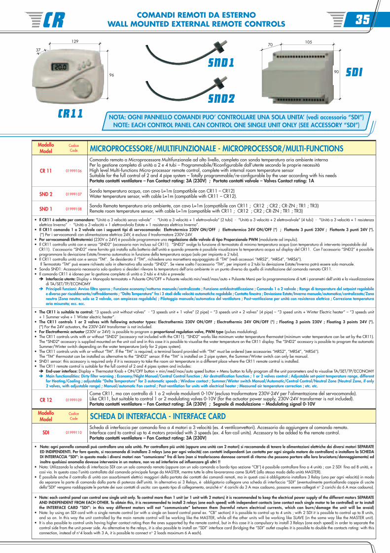
NOTA: OGNI PANNELLO COMANDI PUO’ CONTROLLARE UNA SOLA UNITA’ (vedi accessorio “SDI”)NOTE: EACH CONTROL PANEL CAN CONTROL ONE SINGLE UNIT ONLY (SEE ACCESSORY “SDI”)
ModelloModel
CodiceCode
SND 1 01999108
Comando remoto a Microprocessore Multifunzionale ad alto livello, completo con sonda temperatura aria ambiente internaPer la gestione completa di unità a 2 e 4 tubi – Programmabile/Riconfigurabile dall’utente secondo le proprie necessitàHigh level Multi-functions Micro-processor remote control, complete with internal room temperature sensorSuitable for the full control of 2 and 4 pipe system – Totally programmable/re-configurable by the user according with his needsPortata contatti ventilatore – Fan Contact rating: 3A (230V) ; Portata contatti valvole – Valves Contact rating: 1A
CR 11 01999106
MICROPROCESSORE/MULTIFUNZIONALE - MICROPROCESSOR/MULTI-FUNCTIONS
SND 2 01999107
SDI 01999110
Sonda temperatura acqua, con cavo L=1m (compatibile con CR11 – CR12)Water temperature sensor, with cable L=1m (compatible with CR11 – CR12).
Sonda Remota temperatura aria ambiente, con cavo L=1m (compatibile con CR11 ; CR12 ; CR2 ; CR-ZN ; TR1 ; TR3)Remote room temperature sensor, with cable L=1m (compatible with CR11 ; CR12 ; CR2 ; CR-ZN ; TR1 ; TR3)
Scheda di interfaccia per comando fino a 4 motori a 3 velocità (es. 4 ventilconvettori). Accessorio da aggiungere al comando remoto.Interface card to control up to 4 motors provided with 3 speeds (ex. 4 fan-coil units). Accessory to be added to the remote control.Portata contatti ventilatore – Fan Contact rating: 3A (230V)
CR 12 01999109
ModelloModel
CodiceCode SCHEDA DI INTERFACCIA - INTERFACE CARD
• Il CR11 è adatto per comandare: “Unità a 3 velocità senza valvole” - “Unità a 3 velocità + 1 elettrovalvola” (2 tubi) - “Unità a 3 velocità + 2 elettrovalvole” (4 tubi) - “Unità a 3 velocità + 1 resistenzaelettrica Inverno” - “Unità a 3 velocità + 1 elettrovalvola Estate + 1 resistenza elettrica Inverno”.
• Il CR11 comanda 1 o 2 valvole con i seguenti tipi di servocomando: Elettrotermico 230V ON/OFF ; Elettrotermico 24V ON/OFF (*) ; Flottante 3 punti 230V ; Flottante 3 punti 24V (*).(*) Per i servocomandi con alimentazione elettrica 24V, è escluso il trasformatore 230V-24V.
• Per servocomandi Elettrotermici (230V o 24V) è possibile programmare una regolazione delle valvole di tipo Proporzionale PWM (modulante ad impulsi).• Il CR11 controlla unità con e senza “SND2” (accessorio non incluso sul CR11). “SND2” svolge la funzione di termostato di minima temperatura acqua (con temperatura di intervento impostabile dal CR11). L’accessorio “SND2” viene fornito già installo sulla batteria dell’unità e quando presente è possibile visualizzare la temperatura acqua sul display del CR11. Con l’accessorio “SND2” è possibile
programmare la deviazione Estate/Inverno automatica in funzione della temperatura acqua (solo per impianto a 2 tubi).• Il CR11 controlla unità con e senza “TM”. Se desiderato il “TM”, richiedere una morsettiera equipaggiata di “TM” (vedi accessori “MRS2”, “MRS4”, “MRS6”).
Il Termostato “TM” può essere richiesto solo in alternativa alla sonda “SND2”. Se viene scelto l’accessorio “TM”, per impianti a 2 tubi la deviazione Estate/Inverno potrà essere solo manuale.• Sonda SND1: Accessorio necessario solo qualora si desideri rilevare la temperatura dell’aria ambiente in un punto diverso da quello di installazione del comando remoto CR11.• Il comando CR11 è idoneo per la gestione completa di unità a 2 tubi e 4 tubi e prevede:
Interfaccia utente: Display + Manopola termostato + Pulsante ON/OFF + Pulsante velocità min/med/max/auto + Pulsante Menù per la programmazione di tutti i parametri dell’unità e la visualizzazionedi TA/SET/TP/ECONOMYPrincipali funzioni: Avviso filtro sporco ; Funzione economy/notturno manuale/centralizzata ; Funzione antidestratificazione ; Comando 1 o 2 valvole ; Range di temperature del setpoint regolabilee diverso per riscaldamento/raffreddamento ; “Delta Temperatura” fra i 3 stadi delle velocità automatiche regolabile ; Contatto finestra ; Deviazione Estate/Inverno manuale/automatica/centralizzata/Zonaneutra (Zona neutra, solo se 2 valvole, con ampiezza regolabile) ; Pilotaggio manuale/automatico del ventilatore ; Post-ventilazione per unità con resistenza elettrica ; Correzione temperaturaaria misurata; ecc. ecc.
Come CR11, ma con controllo di 1 o 2 valvole modulanti 0-10V (escluso trasformatore 230V-24V per l’alimentazione del servocomando).Like CR11, but suitable to control 1 or 2 modulating valves 0-10V (for the actuator power supply, 230V-24V transformer is not included).Portata contatti ventilatore – Fan Contact rating: 3A (230V) ; Segnale di modulazione – Modulating signal 0-10V
• Nota: ogni pannello comandi può controllare una sola unità. Per controllare più unità (oppure una unità con 2 motori) si raccomanda di tenere le alimentazioni elettriche dei diversi motori SEPARATEED INDIPENDENTI. Per fare questo, si raccomanda di installare 3 relays (uno per ogni velocità) con contatti indipendenti (un contatto per ogni singolo motore da controllare) o installare la SCHEDADI INTERFACCIA “SDI”: in questo modo i diversi motori non “comunicano” fra di loro (non si trasferiscono dannose correnti di ritorno che possono portare alla loro bruciatura/danneggiamento) edinoltre qualsiasi anomalia dovesse intervenire in un motore, non va ad interferire od influenzare gli altri !!
• Nota: Utilizzando la scheda di interfaccia SDI con un solo comando remoto (oppure con un solo comando a bordo tipo sezione “CB”) è possibile controllare fino a 4 unità ; con 2 SDI fino ad 8 unità, ecosì via. In questo caso l’unità controllata dal comando principale funge da MASTER, mentre tutte le altre lavoreranno come SLAVE (allo stesso modo della unità MASTER).
• É possibile anche il controllo di unità con assorbimenti elettrici maggiori della portata dei contatti dei comandi remoti, ma in questi casi è obbligatorio installare 3 Relay (uno per ogni velocità) in mododa separare la parte di comando dalla parte di potenza dell’unità. In alternativa ai 3 Relays, è obbligatorio collegare una scheda di interfaccia “SDI” (eventualmente ponticellando coppie di uscitedella“SDI” vengono raddoppiate le portate dei suoi contatti di uscita: con questo tipo di collegamento, anziché n° 4 carichi da 3 A max cadauno, possono essere collegati n° 2 carichi da 6 A max cadauno).
• Note: each control panel can control one single unit only. To control more than 1 unit (or 1 unit with 2 motors) it is recommended to keep the electrical power supply of the different motors SEPARATEAND INDEPENDENT FROM EACH OTHER. To obtain this, it is recommended to install 3 relays (one each speed) with independent contacts (one contact each single motor to be controlled) or to installthe INTERFACE CARD “SDI”: in this way different motors will not “communicate” between them (harmful return electrical currents, which can burn/damage the unit will be avoid)
• Note: by using an SDI card with a single remote control (or with a single on board control panel ex. “CB” section) it is possible to control up to 4 units ; with 2 SDI it is possible to control up to 8 units,and so on. In this way the unit controlled by the main remote control will be working like the MASTER, while all the other units will be working like SLAVE (in the same way like the MASTER unit).
• It is also possible to control units having higher contact rating than the ones supported by the remote control, but in this case it is compulsory to install 3 Relays (one each speed) in order to separate thecontrol side from the unit power side. As alternative to the relays, it is also possible to install an “SDI” interface card (bridging the “SDI” outlet couples it is possible to double the contacts rating: with thisconnection, instead of n°4 loads with 3 A, it is possible to connect n° 2 loads maximum 6 A each).
• The CR11 is suitable to control: “3 speeds unit without valves” - “3 speeds unit + 1 valve” (2 pipe) – “3 speeds unit + 2 valves” (4 pipe) – “3 speed units + Winter Electric heater” – “3 speeds unit+ 1 Summer valve + 1 Winter electric heater”.
• The CR11 controls 1 or 2 valves with following actuator types: Electrothermic 230V ON/OFF ; Electrothermic 24V ON/OFF (*) ; Floating 3 points 230V ; Floating 3 points 24V (*).(*) For the 24V actuators, the 230V-24V transformer is not included.
• For Electrothermic actuator (230V or 24V): is possible to program a proportional regulation valve, PWM type (pulses modulating).• The CR11 controls units with or without “SND2” (accessory not included with the CR11). “SND2” works like minimum water temperature thermostat (minimum water temperature can be set by the CR11).
The "SND2" accessory is supplied mounted on the unit coil and in this case it is possible to visualise the water temperature on the CR11 display. The “SND2” accessory is possible to program the automaticSummer/Winter switch depending on the water temperature (only for 2 pipes system).
• The CR11 controls units with or without “TM”. If the “TM” is required, a terminal board provided with “TM” must be ordered (see accessories “MRS2”, “MRS4”, “MRS6”).The “TM” thermostat can be installed as alternative to the “SND2” sensor. If the “TM” is installed on 2 pipe system, the Summer/Winter switch can only be manual.
• SND1 sensor: this accessory is required only if it is necessary to take the room air temperature in a different place where the CR11 remote control is installed.• The CR11 remote control is suitable for the full control of 2 and 4 pipes system and includes:
End-user interface: Display + Thermostat Knob + ON/OFF button + min/med/max/auto speed button + Menu button to fully program all the unit parameters and to visualise TA/SET/TP/ECONOMYMain functionalities: Dirty filter warning ; Economy/Night Manual/Central Control function ; Air destratification function ; 1 or 2 valves control ; Adjustable set-point temperature range, differentfor Heating/Cooling ; adjustable “Delta Temperature” for 3 automatic speeds ; Window contact ; Summer/Winter switch Manual/Automatic/Central Control/Neutral Zone (Neutral Zone, if only2 valves, with adjustable range) ; Manual/automatic Fan control ; Post-ventilation for units with electrical heater ; Measured air temperature correction ; etc. etc.
90 SDI
70105
37
129
96
CR11
CR 35
COMANDI REMOTI DA INCASSOEMBEDDED REMOTE CONTROLS
Finalmente una GammaCompleta di ComandiRemoti da Incasso
at last a CompleteRange of Embedded
Remote Control
ICD12
ICD21 ICD22
La serie ICD è una linea di comandi remoti a parete (a filo, da incasso) conregolazione digitale a microprocessore per la gestione di una vasta gammadi unità terminali con ventilatore 230V a 3 velocità:
• Fan-coils tradizionali e Fan-coils a parete• Cassette ad acqua• Unità canalizzabili piccole e medie (*)• Aerotermi, ecc., ecc.
(*) Il tutto compatibilmente con l’assorbimento elettrico del motore installato sulla unità terminale chedovrà essere inferiore alla portata dei contatti delle schede degli ICD (OK per i fan-coils, da verificareper le canalizzabili). Vedi scheda accessorio scheda SDI.
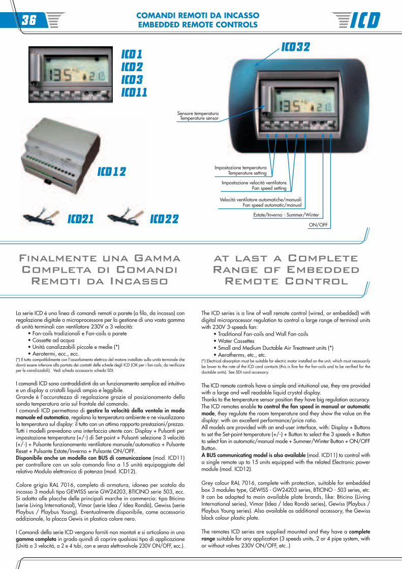
I comandi ICD sono contraddistinti da un funzionamento semplice ed intuitivoe un display a cristalli liquidi ampio e leggibile.Grande è l’accuratezza di regolazione grazie al posizionamento dellasonda temperatura aria sul frontale del comando.I comandi ICD permettono di gestire la velocità della ventola in modomanuale ed automatico, regolano la temperatura ambiente e ne visualizzanola temperatura sul display: il tutto con un ottimo rapporto prestazioni/prezzo.Tutti i modelli prevedono una interfaccia utente con: Display + Pulsanti perimpostazione temperatura (+/-) di Set-point + Pulsanti selezione 3 velocità(+/-) + Pulsante funzionamento ventilatore manuale/automatico + PulsanteReset + Pulsante Estate/Inverno + Pulsante ON/OFF.Disponibile anche un modello con BUS di comunicazione (mod. ICD11)per controllare con un solo comando fino a 15 unità equipaggiate delrelativo Modulo elettronico di potenza (mod. ICD12).
Colore grigio RAL 7016, completo di armatura, idoneo per scatola daincasso 3 moduli tipo GEWISS serie GW24203, BTICINO serie 503, ecc.Si adatta alle placche delle principali marche in commercio: tipo Bticino(serie Living International), Vimar (serie Idea / Idea Rondò), Gewiss (seriePlaybus / Playbus Young). Eventualmente disponibile, come accessorioaddizionale, la placca Gewis in plastica colore nero.
I Comandi della serie ICD vengono forniti non montati e si articolano in unagamma completa in grado quindi di coprire qualsiasi tipo di applicazione(Unità a 3 velocità, a 2 e 4 tubi, con e senza elettrovalvole 230V ON/OFF, ecc.).
The ICD series is a line of wall remote control (wired, or embedded) withdigital microprocessor regulation to control a large range of terminal unitswith 230V 3-speeds fan:
• Traditional Fan-coils and Wall Fan-coils• Water Cassettes• Small and Medium Ductable Air Treatment units (*)• Aerotherms, etc., etc.
(*) Electrical absorption must be suitable for electric motor installed on the unit, which must necessarilybe lower to the rate of the ICD card contacts (this is fine for the fan-coils and to be verified for theductable units). See SDI card accessory.
The ICD remote controls have a simple and intuitional use, they are providedwith a large and well readable liquid crystal display.Thanks to the temperature sensor position they have big regulation accuracy.The ICD remotes enable to control the fan speed in manual or automaticmode, they regulate the room temperature and they show the value on thedisplay: with an excellent performance/price ratio.All models are provided with an end-user interface, with: Display + Buttonsto set the Set-point temperature (+/-) + Button to select the 3 speeds + Buttonto select fan in automatic/manual mode + Summer/Winter Button + ON/OFFButton.A BUS communicating model is also available (mod. ICD11) to control witha single remote up to 15 units equipped with the related Electronic powermodule (mod. ICD12).
Grey colour RAL 7016, complete with protection, suitable for embeddedbox 3 modules type, GEWISS - GW24203 series, BTICINO - 503 series, etc.It can be adapted to main available plate brands, like: Bticino (LivingInternational series), Vimar (Idea / Idea Rondò series), Gewiss (Playbus /Playbus Young series). Also available as additional accessory, the Gewissblack colour plastic plate.
The remotes ICD series are supplied mounted and they have a completerange suitable for any application (3 speeds units, 2 or 4 pipe system, withor without valves 230V ON/OFF, etc..)
ICD1ICD2ICD3ICD11
ICD32
Estate/Inverno - Summer/Winter
ON/OFF
Velocità ventilatore automatiche/manualiFan speed automatic/manual
Sensore temperaturaTemperature sensor
Impostazione velocità ventilatoreFan speed setting
Impostazione temperaturaTemperature setting
ICD36
COMANDI REMOTI DA INCASSOEMBEDDED REMOTE CONTROLS
ModelloModel
CodiceCode
ICD 3 01999203
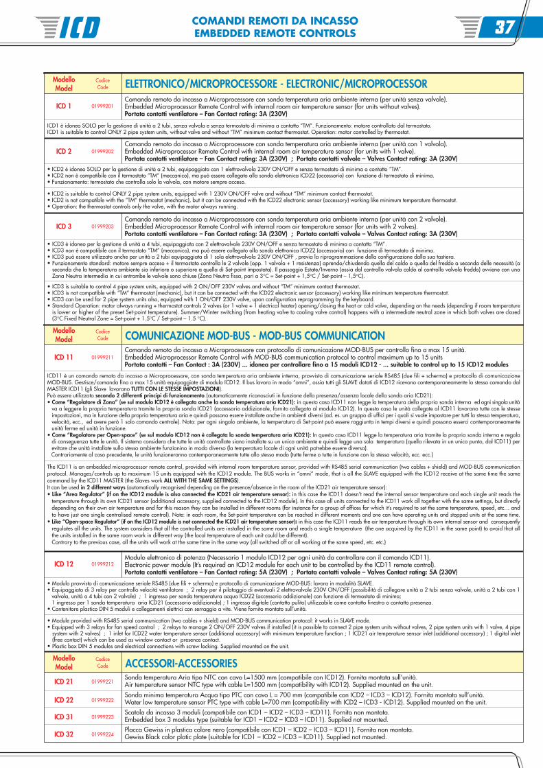
Comando remoto da incasso a Microprocessore con sonda temperatura aria ambiente interna (per unità senza valvole).Embedded Microprocessor Remote Control with internal room air temperature sensor (for units without valves).Portata contatti ventilatore – Fan Contact rating: 3A (230V)
ICD 1 01999201
ELETTRONICO/MICROPROCESSORE - ELECTRONIC/MICROPROCESSOR
ICD 2 01999202
ICD 11 01999211
Comando remoto da incasso a Microprocessore con sonda temperatura aria ambiente interna (per unità con 1 valvola).Embedded Microprocessor Remote Control with internal room air temperature sensor (for units with 1 valve).Portata contatti ventilatore – Fan Contact rating: 3A (230V) ; Portata contatti valvole – Valves Contact rating: 3A (230V)
Comando remoto da incasso a Microprocessore con protocollo di comunicazione MOD-BUS per controllo fino a max 15 unità.Embedded Microprocessor Remote Control with MOD-BUS communication protocol to control maximum up to 15 unitsPortata contatti – Fan Contact : 3A (230V) ... idonea per controllare fino a 15 moduli ICD12 - ... suitable to control up to 15 ICD12 modules
ModelloModel
CodiceCode COMUNICAZIONE MOD-BUS - MOD-BUS COMMUNICATION
• ICD2 è idoneo SOLO per la gestione di unità a 2 tubi, equipaggiata con 1 elettrovalvola 230V ON/OFF e senza termostato di minima a contatto “TM”.• ICD2 non è compatibile con il termostato “TM” (meccanico), ma può essere collegato alla sonda elettronica ICD22 (accessorio) con funzione di termostato di minima.• Funzionamento: termostato che controlla solo la valvola, con motore sempre acceso.
ModelloModel
CodiceCode ACCESSORI-ACCESSORIES
ICD 21 01999221
ICD 22 01999222
ICD 31 01999223
ICD 32 01999224
ICD 12 01999212
ICD1 è idoneo SOLO per la gestione di unità a 2 tubi, senza valvola e senza termostato di minima a contatto “TM”. Funzionamento: motore controllato dal termostato.ICD1 is suitable to control ONLY 2 pipe system units, without valve and without “TM” minimum contact thermostat. Operation: motor controlled by thermostat.
• ICD2 is suitable to control ONLY 2 pipe system units, equipped with 1 230V ON/OFF valve and without “TM” minimum contact thermostat.• ICD2 is not compatible with the “TM” thermostat (mechanic), but it can be connected with the ICD22 electronic sensor (accessory) working like minimum temperature thermostat.• Operation: the thermostat controls only the valve, with the motor always running.
Comando remoto da incasso a Microprocessore con sonda temperatura aria ambiente interna (per unità con 2 valvole).Embedded Microprocessor Remote Control with internal room air temperature sensor (for units with 2 valves).Portata contatti ventilatore – Fan Contact rating: 3A (230V) ; Portata contatti valvole – Valves Contact rating: 3A (230V)
• ICD3 è idoneo per la gestione di unità a 4 tubi, equipaggiata con 2 elettrovalvole 230V ON/OFF e senza termostato di minima a contatto “TM”.• ICD3 non è compatibile con il termostato “TM” (meccanico), ma può essere collegato alla sonda elettronica ICD22 (accessorio) con funzione di termostato di minima.• ICD3 può essere utilizzato anche per unità a 2 tubi equipaggiata di 1 sola elettrovalvola 230V ON/OFF , previa la riprogrammazione della configurazione dalla sua tastiera.• Funzionamento standard: motore sempre acceso + il termostato controlla le 2 valvole (opp. 1 valvola + 1 resistenza) aprendo/chiudendo quella del caldo o quella del freddo a seconda delle necessità (a
seconda che la temperatura ambiente sia inferiore o superiore a quella di Set-point impostata). Il passaggio Estate/Inverno (ossia dal controllo valvola caldo al controllo valvola freddo) avviene con unaZona Neutra intermedia in cui entrambe le valvole sono chiuse (Zona Neutra fissa, pari a 3°C = Set-point + 1,5°C / Set-point – 1,5°C).
• ICD3 is suitable to control 4 pipe system units, equipped with 2 ON/OFF 230V valves and without “TM” minimum contact thermostat.• ICD3 is not compatible with “TM” thermostat (mechanic), but it can be connected with the ICD22 electronic sensor (accessory) working like minimum temperature thermostat.• ICD3 can be used for 2 pipe system units also, equipped with 1 ON/OFF 230V valve, upon configuration reprogramming by the keyboard.• Standard Operation: motor always running + thermostat controls 2 valves (or 1 valve + 1 electrical heater) opening/closing the heat or cold valve, depending on the needs (depending if room temperature
is lower or higher of the preset Set-point temperature). Summer/Winter switching (from heating valve to cooling valve control) happens with a intermediate neutral zone in which both valves are closed(3°C Fixed Neutral Zone = Set-point + 1.5°C / Set-point – 1.5 °C).
ICD11 è un comando remoto da incasso a Microprocessore, con sonda temperatura aria ambiente interna, provvisto di comunicazione seriale RS485 (due fili + schermo) e protocollo di comunicazioneMOD-BUS. Gestisce/comanda fino a max 15 unità equipaggiate di modulo ICD12. Il bus lavora in modo “omni”, ossia tutti gli SLAVE dotati di ICD12 ricevono contemporaneamente lo stesso comando dalMASTER ICD11 (gli Slave lavorano TUTTI CON LE STESSE IMPOSTAZIONI).Può essere utilizzato secondo 2 differenti principi di funzionamento (automaticamente riconosciuti in funzione della presenza/assenza locale della sonda aria ICD21):• Come “Regolatore di Zona” (se sul modulo ICD12 è collegata anche la sonda temperatura aria ICD21): in questo caso ICD11 non legge la temperatura della propria sonda interna ed ogni singola unità
va a leggere la propria temperatura tramite la propria sonda ICD21 (accessorio addizionale, fornito collegato al modulo ICD12). In questo caso le unità collegate al ICD11 lavorano tutte con le stesseimpostazioni, ma in funzione della propria temperatura aria e quindi possono essere installate anche in ambienti diversi (ad. es. un gruppo di uffici per i quali si vuole impostare per tutti la stessa temperatura,velocità, ecc., ed avere però 1 solo comando centrale). Nota: per ogni singolo ambiente, la temperatura di Set-point può essere raggiunta in tempi diversi e quindi possono esserci contemporaneamenteunità ferme ed unità in funzione.
• Come “Regolatore per Open-space” (se sul modulo ICD12 non è collegata la sonda temperatura aria ICD21): In questo caso ICD11 legge la temperatura aria tramite la propria sonda interna e regoladi conseguenza tutte le unità. Il sistema considera che tutte le unità controllate siano installate su un unico ambiente e quindi legge una sola temperatura (quella rilevata in un unico punto, dal ICD11) perevitare che unità installate sullo stesso ambiente funzionino in modo diverso (la temperatura locale di ogni unità potrebbe essere diversa).Contrariamente al caso precedente, le unità funzioneranno contemporaneamente tutte allo stesso modo (tutte ferme o tutte in funzione con la stessa velocità, ecc. ecc.)
The ICD11 is an embedded microprocessor remote control, provided with internal room temperature sensor, provided with RS485 serial communication (two cables + shield) and MOD-BUS communicationprotocol. Manages/controls up to maximum 15 units equipped with the ICD12 module. The BUS works in “omni” mode, that is all the SLAVE equipped with the ICD12 receive at the same time the samecommand by the ICD11 MASTER (the Slaves work ALL WITH THE SAME SETTINGS).It can be used in 2 different ways (automatically recognised depending on the presence/absence in the room of the ICD21 air temperature sensor):• Like “Area Regulator” (if on the ICD12 module is also connected the ICD21 air temperature sensor): in this case the ICD11 doesn’t read the internal sensor temperature and each single unit reads the
temperature through its own ICD21 sensor (additional accessory, supplied connected to the ICD12 module). In this case all units connected to the ICD11 work all together with the same settings, but directlydepending on their own air temperature and for this reason they can be installed in different rooms (for instance for a group of offices for which it’s required to set the same temperature, speed, etc… andto have just one single centralised remote control). Note: in each room, the Set-point temperature can be reached in different moments and one can have operating units and stopped units at the same time.
• Like “Open-space Regulator” (if on the ICD12 module is not connected the ICD21 air temperature sensor): in this case the ICD11 reads the air temperature through its own internal sensor and consequentlyregulates all the units. The system considers that all the controlled units are installed in the same room and reads a single temperature (the one acquired by the ICD11 in the same point) to avoid that allthe units installed in the same room work in different way (the local temperature of each unit could be different).Contrary to the previous case, all the units will work at the same time in the same way (all switched off or all working at the same speed, etc. etc.)
Modulo elettronico di potenza (Necessario 1 modulo ICD12 per ogni unità da controllare con il comando ICD11).Electronic power module (It’s required an ICD12 module for each unit to be controlled by the ICD11 remote control).Portata contatti ventilatore – Fan Contact rating: 5A (230V) ; Portata contatti valvole – Valves Contact rating: 5A (230V)
Sonda temperatura Aria tipo NTC con cavo L=1500 mm (compatibile con ICD12). Fornita montata sull’unità.Air temperature sensor NTC type with cable L=1500 mm (compatibility with ICD12). Supplied mounted on the unit.
Sonda minima temperatura Acqua tipo PTC con cavo L = 700 mm (compatibile con ICD2 – ICD3 – ICD12). Fornita montata sull’unità.Water low temperature sensor PTC type with cable L=700 mm (compatibility with ICD2 – ICD3 - ICD12). Supplied mounted on the unit.Scatola da incasso 3 moduli (compatibile con ICD1 – ICD2 – ICD3 – ICD11). Fornita non montata.Embedded box 3 modules type (suitable for ICD1 – ICD2 – ICD3 – ICD11). Supplied not mounted.Placca Gewiss in plastica colore nero (compatibile con ICD1 – ICD2 – ICD3 – ICD11). Fornita non montata.Gewiss Black color platic plate (suitable for ICD1 – ICD2 – ICD3 – ICD11). Supplied not mounted.
• Modulo provvisto di comunicazione seriale RS485 (due fili + schermo) e protocollo di comunicazione MOD-BUS: lavora in modalità SLAVE.• Equipaggiato di 3 relay per controllo velocità ventilatore ; 2 relay per il pilotaggio di eventuali 2 elettrovalvole 230V ON/OFF (possibilità di collegare unità a 2 tubi senza valvole, unità a 2 tubi con 1
valvola, unità a 4 tubi con 2 valvole) ; 1 ingresso per sonda temperatura acqua ICD22 (accessorio addizionale) con funzione di termostato di minima;1 ingresso per 1 sonda temperatura aria ICD21 (accessorio addizionale) ; 1 ingresso digitale (contatto pulito) utilizzabile come contatto finestra o contatto presenza.
• Contenitore plastico DIN 5 moduli e collegamenti elettrici con serraggio a vite. Viene fornito montato sull’unità.
• Module provided with RS485 serial communication (two cables + shield) and MOD-BUS communication protocol: it works in SLAVE mode.• Equipped with 3 relays for fan speed control ; 2 relays to manage 2 ON/OFF 230V valves if installed (it is possible to connect 2 pipe system units without valves, 2 pipe system units with 1 valve, 4 pipe
system with 2 valves) ; 1 inlet for ICD22 water temperature sensor (additional accessory) with minimum temperature function ; 1 ICD21 air temperature sensor inlet (additional accessory) ; 1 digital inlet(free contact) which can be used as window contact or presence contact.
• Plastic box DIN 5 modules and electrical connections with screw locking. Supplied mounted on the unit.
ICD 37
REGOLAZIONE HI-TECHHI-TECH REGULATION
una Regolazioneall’Avanguardia cheAnticipa le Esigenzedel Terzo Millennio
the Avant-gardeRegulation Advancingthe Third Millennium
needs
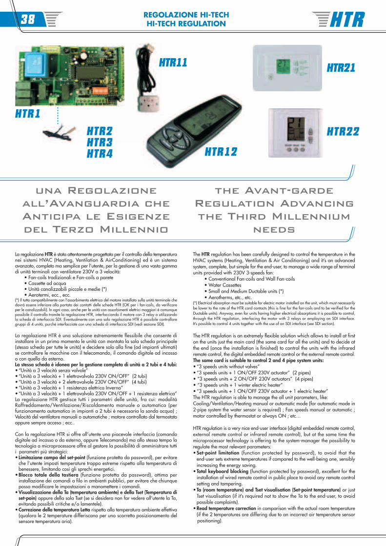
La regolazione HTR è stata attentamente progettata per il controllo della temperaturanei sistemi HVAC (Heating, Ventilation & AirConditioning) ed è un sistemaavanzato, completo ma semplice per l’utente, per la gestione di una vasta gammadi unità terminali con ventilatore 230V a 3 velocità:
• Fan-coils tradizionali e Fan-coils a parete• Cassette ad acqua• Unità canalizzabili piccole e medie (*)• Aerotermi, ecc., ecc.
(*) Il tutto compatibilmente con l’assorbimento elettrico del motore installato sulla unità terminale chedovrà essere inferiore alla portata dei contatti delle schede HTR (OK per i fan-coils, da verificareper le canalizzabili). In ogni caso, anche per le unità con assorbimenti elettrici maggiori è comunquepossibile il controllo tramite la regolazione HTR, interfacciando il motore con 3 relay o utilizzandola scheda di interfaccia SDI. Eventualmente con una sola regolazione HTR è possibile controllaregruppi di 4 unità, purché interfacciate con una scheda di interfaccia SDI (vedi sezione SDI).
La regolazione HTR è una soluzione estremamente flessibile che consente diinstallare in un primo momento le unità con montata la sola scheda principale(stessa scheda per tutte le unità) e decidere solo alla fine (ad impianti ultimati)se controllare le macchine con il telecomando, il comando digitale ad incassoo con quello da esterno.La stessa scheda è idonea per la gestione completa di unità a 2 tubi e 4 tubi:• “Unità a 3 velocità senza valvole”• “Unità a 3 velocità + 1 elettrovalvola 230V ON/OFF” (2 tubi)• “Unità a 3 velocità + 2 elettrovalvole 230V ON/OFF” (4 tubi)• “Unità a 3 velocità + 1 resistenza elettrica Inverno”• “Unità a 3 velocità + 1 elettrovalvola 230V ON/OFF + 1 resistenza elettrica”La regolazione HTR gestisce tutti i parametri delle unità, fra cui: modalitàRaffreddamento/Ventilazione/Riscaldamento manuale o automatica (perfunzionamento automatico in impianti a 2 tubi è necessaria la sonda acqua) ;Velocità del ventilatore manuali o automatiche ; motore controllato dal termostatooppure sempre acceso ; ecc..
Con la regolazione HTR si offre all’utente una piacevole interfaccia (comandodigitale ad incasso o da esterno, oppure Telecomando) ma allo stesso tempo latecnologia a microprocessore offre al gestore la possibilità di amministrare tuttii parametri più strategici:• Limitazione campo del set-point (funzione protetta da password), per evitare
che l’utente imposti temperature troppo estreme rispetto alla temperatura dibenessere, limitando così gli sprechi energetici.
• Blocco totale della tastiera (funzione protetta da password), ottima perinstallazione dei comandi a filo in ambienti pubblici, per evitare che chiunquepossa modificare le impostazioni o manomettere i comandi.
• Visualizzazione della Ta (temperatura ambiente) e della Tset (Temperatura diset-poin) oppure della sola Tset (se si desidera non far vedere all’utente la Ta,evitando possibili critiche e/o lamentele).
• Correzione della temperatura Letta rispetto alla temperatura ambiente effettiva(qualora le 2 temperature differiscano per uno scorretto posizionamento delsensore temperatura aria).
The HTR regulation has been carefully designed to control the temperature in theHVAC systems (Heating, Ventilation & Air Conditioning) and it’s an advancedsystem, complete, but simple for the end-user, to manage a wide range of terminalunits provided with 230V 3-speeds fan: • Conventional Fan-coils and Wall Fan-coils • Water Cassettes • Small and Medium Ductable units (*) • Aerotherms, etc., etc.(*) Electrical absorption must be suitable for electric motor installed on the unit, which must necessarilybe lower to the rate of the HTR card contacts (this is fine for the fan-coils and to be verified for theDuctable units). Anyway, even for units having higher electrical absorptions it is possible to control,through the HTR regulation, interfacing the motor with 3 relays or employing an SDI interface.It’s possible to control 4 units together with the use of an SDI interface (see SDI section).
The HTR regulation is an extremely flexible solution which allows to install at firston the units just the main card (the same card for all the units) and to decide atthe end (once the installation is finished) to control the units with the infraredremote control, the digital embedded remote control or the external remote control.The same card is suitable to control 2 and 4 pipe system units:• “3 speeds units without valves”• “3 speeds units + 1 ON/OFF 230V actuator” (2 pipes)• “3 speeds units + 2 ON/OFF 230V actuators” (4 pipes)• “3 speeds units + 1 winter electric heater”• “3 speeds units + 1 ON/OFF 230V actuator + 1 electric heater”The HTR regulation is able to manage the all unit parameters, like:Cooling/Ventilation/Heating manual or automatic mode (for automatic mode in2-pipe system the water sensor is required) ; Fan speeds manual or automatic ;motor controlled by thermostat or always ON ; etc…
HTR regulation is a very nice end-user interface (digital embedded remote control,external remote control or infrared remote control), but at the same time themicroprocessor technology is offering to the system-manager the possibility toregulate the most relevant parameters:• Set-point limitation (function protected by password), to avoid that the
end-user sets extreme temperatures if compared to the well-being one, sensiblyincreasing the energy saving.
• Total keyboard blocking (function protected by password), excellent for theinstallation of wired remote control in public place to avoid any remote controlsetting and tampering.
• Ta (room temperature) and Tset visualisation (Set-point temperature) or justTset visualisation (if it’s required not to show the Ta to the end-user, to avoidpossible complaints).
• Read temperature correction in comparison with the actual room temperature(if the 2 temperatures are differing due to an incorrect air temperature sensor
positioning).
HTR22
HTR21
HTR2HTR3HTR4
HTR11
HTR1
HTR12
HTR38
REGOLAZIONE HI-TECHHI-TECH REGULATION
ModelloModel
CodiceCode
HTC 1 01999331
HTC 2 01999332
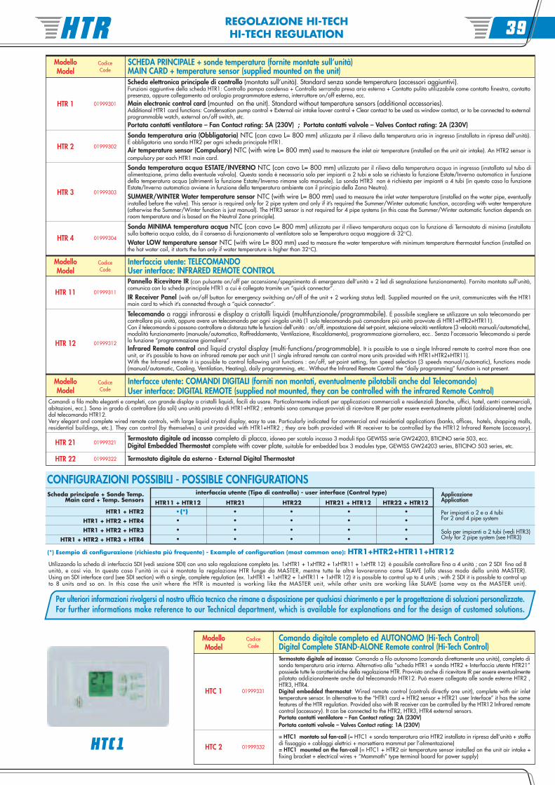
Termostato digitale ad incasso: Comando a filo autonomo (comanda direttamente una unità), completo disonda temperatura aria interna. Alternativo alla “scheda HTR1 + sonda HTR2 + Interfaccia utente HTR21”possiede tutte le caratteristiche della regolazione HTR. Provvisto anche di ricevitore IR per essere eventualmentepilotato addizionalmente anche dal telecomando HTR12. Può essere collegato alle sonde esterne HTR2 ,HTR3, HTR4.Digital embedded thermostat: Wired remote control (controls directly one unit), complete with air inlettemperature sensor. In alternative to the “HTR1 card + HTR2 sensor + HTR21 user Interface” it has the samefeatures of the HTR regulation. Provided also with IR receiver can be controlled by the HTR12 Infrared remotecontrol (accessory). It can be connected to the HTR2, HTR3, HTR4 external sensors.Portata contatti ventilatore – Fan Contact rating: 2A (230V)Portata contatti valvole – Valves Contact rating: 1A (230V)
Comando digitale completo ed AUTONOMO (Hi-Tech Control)Digital Complete STAND-ALONE Remote control (Hi-Tech Control)
= HTC1 montato sul fan-coil (= HTC1 + sonda temperatura aria HTR2 installata in ripresa dell’unità + staffadi fissaggio + cablaggi elettrici + morsettiera mammut per l’alimentazione)= HTC1 mounted on the fan-coil (= HTC1 + HTR2 air temperature sensor installed on the unit air intake +fixing bracket + electrical wires + “Mammoth” type terminal board for power supply)
HTC1
ModelloModel
CodiceCode
HTR 3 01999303
Scheda elettronica principale di controllo (montata sull’unità). Standard senza sonde temperatura (accessori aggiuntivi).Funzioni aggiuntive della scheda HTR1: Controllo pompa condensa + Controllo serranda presa aria esterna + Contatto pulito utilizzabile come contatto finestra, contattopresenza, oppure collegamento ad orologio programmatore esterno, interruttore on/off esterno, ecc.Main electronic control card (mounted on the unit). Standard without temperature sensors (additional accessories).Additional HTR1 card functions: Condensation pump control + External air intake louver control + Clear contact to be used as window contact, or to be connected to externalprogrammable watch, external on/off switch, etc.Portata contatti ventilatore – Fan Contact rating: 5A (230V) ; Portata contatti valvole – Valves Contact rating: 2A (230V)
HTR 1 01999301
HTR 2 01999302
HTR 11 01999311
Sonda temperatura aria (Obbligatoria) NTC (con cavo L= 800 mm) utilizzata per il rilievo della temperatura aria in ingresso (installata in ripresa dell’unità).É obbligatoria una sonda HTR2 per ogni scheda principale HTR1.Air temperature sensor (Compulsory) NTC (with wire L= 800 mm) used to measure the inlet air temperature (installed on the unit air intake). An HTR2 sensor iscompulsory per each HTR1 main card.
Pannello Ricevitore IR (con pulsante on/off per accensione/spegnimento di emergenza dell’unità + 2 led di segnalazione funzionamento). Fornito montato sull’unità,comunica con la scheda principale HTR1 a cui è collegato tramite un “quick connector”.
IR Receiver Panel (with on/off button for emergency switching on/off of the unit + 2 working status led). Supplied mounted on the unit, communicates with the HTR1main card to which it’s connected through a “quick connector”.
ModelloModel
CodiceCode
Interfaccia utente: TELECOMANDO
HTR 22 01999322
Sonda temperatura acqua ESTATE/INVERNO NTC (con cavo L= 800 mm) utilizzata per il rilievo della temperatura acqua in ingresso (installata sul tubo dialimentazione, prima della eventuale valvola). Questa sonda è necessaria solo per impianti a 2 tubi e solo se richiesta la funzione Estate/Inverno automatica in funzionedella temperatura acqua (altrimenti la funzione Estate/Inverno rimane solo manuale). La sonda HTR3 non è richiesta per impianti a 4 tubi (in questo caso la funzioneEstate/Inverno automatica avviene in funzione della temperatura ambiente con il principio della Zona Neutra).
SUMMER/WINTER Water temperature sensor NTC (with wire L= 800 mm) used to measure the inlet water temperature (installed on the water pipe, eventuallyinstalled before the valve). This sensor is required only for 2 pipe system and only if it’s required the Summer/Winter automatic function, according with water temperature(otherwise the Summer/Winter function is just manual). The HTR3 sensor is not required for 4 pipe systems (in this case the Summer/Winter automatic function depends onroom temperature and is based on the Neutral Zone principle).
Comandi a filo molto eleganti e completi, con grande display a cristalli liquidi, facili da usare. Particolarmente indicati per applicazioni commerciali e residenziali (banche, uffici, hotel, centri commerciali,abitazioni, ecc.). Sono in grado di controllare (da soli) una unità provvista di HTR1+HTR2 ; entrambi sono comunque provvisti di ricevitore IR per poter essere eventualmente pilotati (addizionalmente) anchedal telecomando HTR12.Very elegant and complete wired remote controls, with large liquid crystal display, easy to use. Particularly indicated for commercial and residential applications (banks, offices, hotels, shopping malls,residential buildings, etc.). They can control (by themselves) a unit provided with HTR1+HTR2 ; they are both provided with IR receiver to be controlled by the HTR12 Infrared Remote (accessory).
HTR 4 01999304
User interface: INFRARED REMOTE CONTROL
HTR 12 01999312
ModelloModel
CodiceCode
Interfacce utente: COMANDI DIGITALI (forniti non montati, eventualmente pilotabili anche dal Telecomando)User interface: DIGITAL REMOTE (supplied not mounted, they can be controlled with the infrared Remote Control)
HTR 21 01999321Termostato digitale ad incasso completo di placca, idoneo per scatola incasso 3 moduli tipo GEWISS serie GW24203, BTICINO serie 503, ecc.Digital Embedded Thermostat complete with cover plate, suitable for embedded box 3 modules type, GEWISS GW24203 series, BTICINO 503 series, etc.
SCHEDA PRINCIPALE + sonde temperatura (fornite montate sull’unità)MAIN CARD + temperature sensor (supplied mounted on the unit)
Sonda MINIMA temperatura acqua NTC (con cavo L= 800 mm) utilizzata per il rilievo temperatura acqua con la funzione di Termostato di minima (installatasulla batteria acqua calda, da il consenso di funzionamento al ventilatore solo se Temperatura acqua maggiore di 32°C).
Water LOW temperature sensor NTC (with wire L= 800 mm) used to measure the water temperature with minimum temperature thermostat function (installed onthe hot water coil, it starts the fan only if water temperature is higher than 32°C).
Telecomando a raggi infrarossi e display a cristalli liquidi (multifunzionale/programmabile). É possibile scegliere se utilizzare un solo telecomando percontrollare più unità, oppure avere un telecomando per ogni singola unità (1 solo telecomando può comandare più unità provviste di HTR1+HTR2+HTR11).Con il telecomando si possono controllare a distanza tutte le funzioni dell’unità : on/off, impostazione del set-point, selezione velocità ventilatore (3 velocità manuali/automatiche),modalità funzionamento (manuale/automatico, Raffreddamento, Ventilazione, Riscaldamento), programmazione giornaliera, ecc.. Senza l’accessorio Telecomando si perdela funzione “programmazione giornaliera”.Infrared Remote control and liquid crystal display (multi-functions/programmable). It is possible to use a single Infrared remote to control more than oneunit, or it’s possible to have an infrared remote per each unit (1 single infrared remote can control more units provided with HTR1+HTR2+HTR11).With the Infrared remote it is possible to control following unit functions : on/off, set-point setting, fan speed selection (3 speeds manual/automatic), functions mode(manual/automatic, Cooling, Ventilation, Heating), daily programming, etc.. Without the Infrared Remote Control the “daily programming” function is not present.
Termostato digitale da esterno - External Digital Thermostat
Utilizzando la scheda di interfaccia SDI (vedi sezione SDI) con una sola regolazione completa (es. 1xHTR1 + 1xHTR2 + 1xHTR11 + 1xHTR 12) è possibile controllare fino a 4 unità ; con 2 SDI fino ad 8unità, e così via. In questo caso l’unità in cui è montata la regolazione HTR funge da MASTER, mentre tutte le altre lavoreranno come SLAVE (allo stesso modo della unità MASTER).Using an SDI interface card (see SDI section) with a single, complete regulation (ex. 1xHTR1 + 1xHTR2 + 1xHTR11 + 1xHTR 12) it is possible to control up to 4 units ; with 2 SDI it is possible to control upto 8 units and so on. In this case the unit where the HTR is mounted is working like the MASTER unit, while other units are working like SLAVE (same way as the MASTER unit).
Scheda principale + Sonde Temp.Main card + Temp. Sensors
CONFIGURAZIONI POSSIBILI - POSSIBLE CONFIGURATIONSApplicazioneApplication
HTR1 + HTR2
HTR1 + HTR2 + HTR4
HTR1 + HTR2 + HTR3
HTR1 + HTR2 + HTR3 + HTR4
HTR11 + HTR12 HTR21 HTR22 HTR21 + HTR12 HTR22 + HTR12
(*) Esempio di configurazione (richiesta più frequente) - Example of configuration (most common one): HTR1+HTR2+HTR11+HTR12
Per impianti a 2 e a 4 tubiFor 2 and 4 pipe system
Solo per impianti a 2 tubi (vedi HTR3)Only for 2 pipe system (see HTR3)
interfaccia utente (Tipo di controllo) - user interface (Control type)
•(*) • •• •
• • •• •
• • •• •
• • •• •
Per ulteriori informazioni rivolgersi al nostro ufficio tecnico che rimane a disposizione per qualsiasi chiarimento e per le progettazione di soluzioni personalizzate.For further informations make reference to our Technical department, which is available for explanations and for the design of customed solutions.
HTR 39
RETE DI LAVORO HI-TECHHI-TECH NETWORK
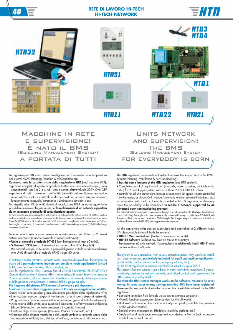
La regolazione HTN è un sistema intelligente per il controllo della temperaturanei sistemi HVAC (Heating, Ventiion & AirConditioning).Conserva tutte le caratteristiche della regolazione HTR (vedi sezione HTR):• gestione completa di qualsiasi tipo di unità (fan-coils, cassette ad acqua, unità
canalizzabili, ecc.) a 2 e 4 tubi, con e senza elettrovalvole 230V ON/OFF• gestione di tutti i parametri dell’unità (velocità del ventilatore manuali o
automatiche; motore controllato dal termostato, oppure sempre acceso ;funzionamento manuale/automatico ; Limitazione set-point ; ecc.)
Ma rispetto alla HTR, le unità dotate di regolazione HTN hanno in aggiunta lapossibilità di essere collegate in rete per la realizzazione di un network supportatoda un avanzato protocollo di comunicazione aperto.Le diverse unità vengono collegate in rete tramite un collegamento di tipo seriale RS 485: in praticale diverse schede che controllano le singole unità devono essere collegate fra loro tramite un cavo(tipo 22 AWG) con 2 fili + schermo che potrà avere una lunghezza max. totale pari a 700 m.Per lunghezze superiori è necessario installare una Unità di controllo principale (HTN31) che fungeda router/ripetitore.
Tutte le unità in rete possono essere supervisionate e controllate con 2 diversisistemi alternativi (è anche possibile installarli entrambi):• Unità di controllo principale HTN31 (con limitazione di max 60 unità).• Software HTN32 (senza limitazioni sul numero di unità collegabili).
Per network con più di 60 unità, è però obbligatorio installare addizionalmenteuna Unità di controllo principale HTN31 ogni 60 unità.
Il sistema è molto attrattivo, a basto costo, semplice da installare, facilissimo dausare ed è particolarmente indicato per piccole e medie applicazioni (piccolihotel, banche, centri servizi, uffici aziendali, ecc.).Con la regolazione HTN si arriva fino al 20% di RISPARMIO ENERGETICO !Questo significa che il sistema HTN si ammortizza in tempi brevissimi, max in2 anni: in pratica, oltre ad avere tutti i benefici di un network, della supervisionee della gestione centralizzata, il sistema HTN si paga da solo !!Più il gestore del sistema HTN lavora sul software e più risparmia.In alcuni casi sono state raggiunte punte di Risparmio energetico fino al 40%.Questi risultati sono possibili grazie alle infinite possibilità della regolazione HTN:• Limitazione campo set-point (evitando sprechi per set-point estremi).• Programma di funzionamento settimanale (singoli giorni di tutta la settimana).• Accensione delle unità solo quando l’ambiente è effettivamente utilizzato
(disponibile anche il contatto presenza o il contatto finestra).• Gestione degli eventi speciali (Vacanze, Periodi di inattività, ecc.)• Gestione della singola macchina e del singolo ambiente, tenendo conto della
sua esposizione Nord/Sud, del tipo di utilizzo, del tempo di utilizzo, ecc. ecc.
The HTN regulation is an intelligent system to control the temperature in the HVACsystems (Heating, Ventilation & Air Conditioning).It has the same features of the HTR regulation (see HTR section):• Complete control of any kind of unit (fan-coils, water cassettes, ductable units,
etc.) for 2 and 4 pipe system, with or without 230V ON/OFF valves• controls the all unit parameters (manual or automatic fan speed ; motor controlled by thermostat, or always ON ; manual/automatic function; set-point limitations ; etc.)In comparison with the HTR, the units provided with HTN regulation additionallyhave the possibility to be connected to realise a network supported by anadvanced open communicating protocol.The different units are connected in a network through a serial connection RS 485 type: the electroniccards controlling the single units must be practically connected through a cable (type 22 AWG) with2 wires + shield, for a total maximum 700m length. For longer length it necessary to install anadditional main control (HTN31) working as a router/repeater.
All the networked units can be supervised and controlled in 2 different ways(it’s also possible to install both the systems):• HTN31 Main control unit (limited to maximum 60 units).• HTN32 Software (without any limit on the units quantity).
For more than 60 units network, it’s compulsory to additionally install HTN31maincontrol unit each 60 units.
The system is very attractive, with a very attractive price, very simple to install,very easy to use and particularly indicated for small and medium applications(small hotels, banks, service centres, company offices, etc.).By the HTN regulation is possible an ENERGY SAVING up to 20% !This means that the system is paid back in very short time, maximum 2 years :practically, besides the network benefits, centralised control and supervision, theHTN system is paid by itself !!The more the HTN system manager works on the software, the more he savesmoney. In some cases energy savings reaching 40% have been registered.These results are possible due to the innumerable possibilities offered by the HTNregulation:• Set-point limitation field (avoids waste due to extreme set-points).• Weekly functioning program (day by day for the all week).• Unit switched-on when the room is actually occupied (available the presence
or the window contact).• Special events management (Holidays, Inactivity periods, etc.)• Single unit and single room management, considering its North/South exposure, kind of use, time of use, etc.
HTN3HTN4
Macchine in retee supervisione:È nato il BMS
(Building Management System)
a portata di Tutti
Units Networkand supervision:
the BMS(Building Management System)
for everybody is born
HTN32
HTN21HTN22
HTN1HTN31
HTN11
HTN40
RETE DI LAVORO HI-TECHHI-TECH NETWORK
ModelloModel
CodiceCode
HTN 3 01999403
Scheda di comando con comunicazione integrata. Fornita montata sull’unità, standard con sonda temperatura aria compresa.La comunicazione integrata consente di collegare in rete la scheda HTN1 che fungerà da unità locale del network.Grazie alle selezioni tramite jumper risulta essere una scheda completa e flessibile che consente di avere un unico comando per tutti i tipi di applicazioni (2 e 4 tubi, cone senza valvole 230V ON/OFF). Pre-programmata in fabbrica al fine di risparmiare tempo in sede di installazione.Accessori: Termostati digitali (non intelligenti, per il controllo locale) a parete (HTN22) o ad incasso (HTN21), sonde temperatura acqua (HTN3 ed HTN4).
Electronic card with integrated communication control. Supply mounted on the unit, standard is including air temperature sensor.The integrated communication allows to connect in network the HTN1 card, which will be working as the local unit network.Thanks to the jumper selection this is a very complete and flexible card which allows to have a single remote for any application (for 2 and 4 pipe system, with or withoutvalves 230V ON/OFF). The device is pre-programmed in the factory to save time during installation.Accessories: digital thermostats (not intelligent, for local control) wall mounted (HTN22) or embedded thermostats (HTN21), water sensors (HTN3 and HTN4).Portata contatti ventilatore – Fan Contact rating: 5A (230V) ; Portata contatti valvole – Valves Contact rating: 2A (230V)
HTN 1 01999401
SCHEDA e COMANDO CON COMUNICAZIONE INTEGRATA + sonde temperatura
HTN 11 01999411
HTN 4 01999404
Termostato digitale ad incasso con comunicazione integrata (in alternativa alla scheda HTN1) completo di sonda temperatura aria interna.La comunicazione integrata consente di collegare in rete il termostato HTN11 che fungerà da unità locale del network.E’ in grado di comandare e regolare una vasta gamma di sistemi HVAC secondo diverse configurazioni.Prevede: Dip-switch di indirizzamento ; Dip-switch di configurazione ; Limiti di set-point (protezione tramite password) ; Pre-programmato in fabbrica.Fornito non montato sull’unità. - Accessori: sonde temperatura acqua (HTN3 ed HTN4).
Digital embedded Thermostat with integrated communication (as alternative to HTN1 card) complete with room air temperature.The integrated communication allows to connect in network the HTN11 thermostat which will be working as the local unit network.It’s able to control and regulate a wide HVAC system range, in different configurations.Provided with: directing dip-switch ; configuration dip-switch ; set-point limits (protected by password) ; factory pre-programmed.Supplied mounted on the unit. - Accessories: water temperature sensors (HTN3 and HTN4).Portata contatti ventilatore – Fan Contact rating: 2A (230V) ; Portata contatti valvole – Valves Contact rating: 1A (230V)
Sonda MINIMA temperatura acqua NTC (con cavo L=800 mm) utilizzata per il rilievo temperatura acqua con la funzione di Termostato di minima (installatasulla batteria acqua calda, da il consenso di funzionamento al ventilatore solo se Temperatura acqua maggiore di 32°C).
Water LOW temperature sensor NTC (with wire L=800 mm) used to measure the water temperature with minimum temperature thermostat function (installed onthe hot water coil, it starts the fan only if water temperature is higher than 32°C).
ModelloModel
CodiceCode
ModelloModel
CodiceCode
HTN 31 01999431
HTN 32 01999432
HTN 21 01999421
Sonda temperatura acqua ESTATE/INVERNO NTC (con cavo L=800 mm) utilizzata per il rilievo della temperatura acqua in ingresso (installata sul tubo dialimentazione, prima della eventuale valvola 230V ON/OFF). Questa sonda è necessaria solo per impianti a 2 tubi e solo se richiesta la funzione Estate/Inverno automaticain funzione della temperatura acqua (altrimenti la funzione Estate/Inverno rimane solo manuale). La sonda HTN3 non è richiesta per impianti a 4 tubi (in questo caso lafunzione Estate/Inverno automatica avviene in funzione della temperatura ambiente con il principio della Zona Neutra).
SUMMER/WINTER Water temperature sensor NTC (with wire L=800 mm) used to measure the inlet water temperature (placed on the water pipe, before the230V ON/OFF valve, if installed). This sensor is required only for 2 pipe system and only if it’s required the Summer/Winter automatic function, according with watertemperature (otherwise the Summer/Winter function is just manual). The HTN3 sensor is not required for 4 pipe systems (in this case the Summer/Winter automatic functiondepends on room temperature and is based on the Neutral Zone principle).
Comandi a filo molto eleganti e completi, con grande display a cristalli liquidi, facili da usare. Particolarmente indicati per applicazioni commerciali (banche, uffici, hotel, centri commerciali, ecc.). Sono ingrado di controllare una unità provvista di scheda HTN1. Offrono la possibilità di lasciare all’utente una gradevole interfaccia per il controllo locale dell’unità (con tutte le limitazioni stabilite ed impostetramite l’unità di controllo principale HTN31 (o software HTN32)). Esempio di applicazione: in un albergo si può decidere di installare in ogni camera un comando tipo HTN21 o HTN22, per lasciare alcliente dell’albergo la possibilità di controllare localmente la propria unità (provvista di HTN1) , mentre le unità installate sui corridoi, reception, locali ausiliari, ecc. (sempre equipaggiate della stessa schedaHTN1) possono essere controllate direttamente dal software HTN32 (o dall’unità di controllo HTN31).
Very elegant and complete wired remote controls, with big liquid crystal display, easy to use. Particularly indicated for commercial and residential applications (banks, offices, hotels, shopping malls, residentialbuildings, etc.). They can control a unit provided with the HTN1 card. They offer to the end-user a suitable interface for the local control of the unit (parameters range is limited trough the HTN31 main controlunit (or through the software HTN32)). Example of application: in an hotel one can install in each room an HTN21 or HTN22 remote control, in order to enable the customer to locally control the unit (providedwith HTN1), while units installed in the corridors, reception, auxiliary rooms, etc... (all the units equipped with HTN1 card) can be controlled directly by the HTN32 software (or by HTN31 control unit).
Termostato digitale ad incasso completo di placca, idoneo per scatola incasso 3 moduli tipo GEWISS serie GW24203, BTICINO serie 503, ecc.Digital Embedded Thermostat complete with cover plate, suitable for embedded box 3 modules type, GEWISS - GW24203 series, BTICINO - 503 series, etc.
Unità di controllo principale per il sistema HTN (idonea, e particolarmente indicata, per gestire network fino a 60 termostati).Adatta per applicazioni “Stand alone” oppure Software. La HTN31 viene utilizzata come router nelle applicazioni dove la rete è costituita da più di 60 termostati oppuresemplicemente per creare delle divisioni particolari all’ interno del network (piani, zone, sezioni…).E’ dotata di un grande display per visualizzare e modificare le impostazioni delle singole unità che costituiscono il network.E’ dotata di un programma settimanale interno di emergenza che si attiva automaticamente in caso di problemi di funzionamento al software.Principali caratteristiche: Verifica e regolazione delle unità costituenti il network ; Consente la semplice modifica dei parametri di regolazione (Modo ; Velocità del ventilatore ;Set-point di temperatura ; Limiti di Set-point ; On/Off) ; Programma settimanale 7 gg; 2 orari ; Start-stop e Set-point per ogni periodo ; Programma settimanale diemergenza con attivazione automatica in caso di problemi al software ; Dip-switch di selezione per applicazioni “stand alone” oppure Software. - Fornita non montatasull’unità. - Controlla/gestisce unità equipaggiate di HTN1 o HTN11.
Main control unit for HTN system (suitable and particularly indicated to manage up to 60 thermostats).Suitable for “Stand-alone” applications or Software. The HTN31 is used as router in the applications in which the network is built with more than 60 thermostats or simplyto create some special divisions inside the network (floors, areas, sections,…).Its’ provided with a big liquid crystal display to modify the settings of each unit network.It’s provided with an internal emergency weekly program which is automatically activated if some software inconvenience occur.Main features: units network Verify and regulation ; Allows the simple regulation parameters modification (Mode ; Fan speed ; Temperature Set-point ; Set-point limits ;On/Off) ; 7 days weekly program ; 2 timings ; Start-stop and each period Set-point ; Emergency weekly program with automatic activation if some software inconvenienceoccur ; Dip-switch to select the application: “stand alone” or Software. - Supplied not mounted on the unit - Control / Manage units provided with HTN1 or HTN11.
HTN 22 01999422 Termostato digitale da esterno - External Digital Thermostat
ELECTRONIC CARD and CONTROL WITH INTEGRATED COMMUNICATION + temperature sensor
Interfacce utente: COMANDI DIGITALI “NON INTELLIGENTI” PER IL CONTROLLO LOCALEUser Interface: DIGITAL CONTROL “NOT INTELLIGENT” FOR LOCAL CONTROL
SISTEMI DI GESTIONE DELLA RETENETWORK MANAGEMENT SYSTEM
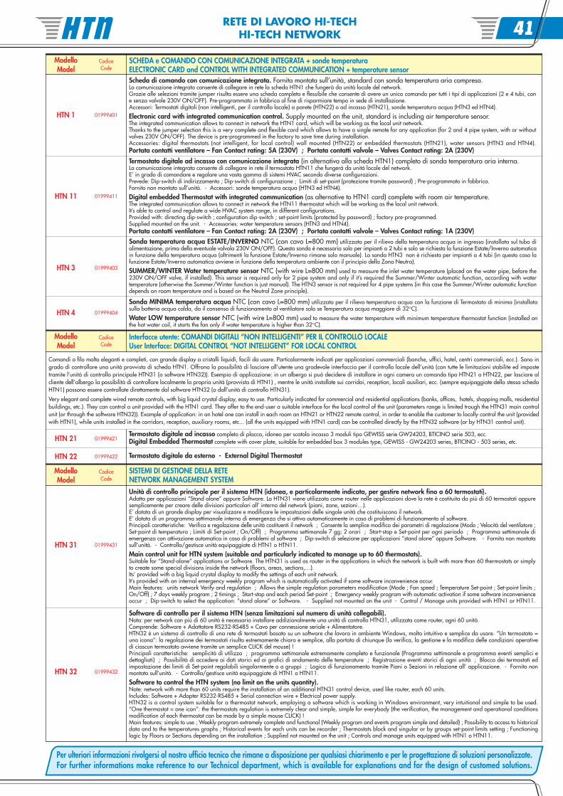
Software di controllo per il sistema HTN (senza limitazioni sul numero di unità collegabili).Nota: per network con più di 60 unità è necessario installare addizionalmente una unità di controllo HTN31, utilizzata come router, ogni 60 unità.Comprende: Software + Adattatore RS232-RS485 + Cavo per connessione seriale + Alimentatore.HTN32 è un sistema di controllo di una rete di termostati basato su un software che lavora in ambiente Windows, molto intuitivo e semplice da usare. “Un termostato =una icona”: la regolazione dei termostati risulta estremamente chiara e semplice, alla portata di chiunque (la verifica, la gestione e la modifica delle condizioni operativedi ciascun termostato avviene tramite un semplice CLICK del mouse) !Principali caratteristiche: semplicità di utilizzo ; programma settimanale estremamente completo e funzionale (Programma settimanale e programma eventi semplici edettagliati) ; Possibilità di accedere ai dati storici ed ai grafici di andamento delle temperature ; Registrazione eventi storici di ogni unità ; Blocco dei termostati edimpostazione dei limiti di Set-point regolabili singolarmente o a gruppi ; Logica di funzionamento tramite Piani o Sezioni in relazione all’ applicazione. - Fornito nonmontato sull’unità. - Controlla/gestisce unità equipaggiate di HTN1 o HTN11.
Software to control the HTN system (no limit on the units quantity).Note: network with more than 60 units require the installation of an additional HTN31 control device, used like router, each 60 units.Includes: Software + Adapter RS232-RS485 + Serial connection wire + Electrical power supply.HTN32 is a control system suitable for a thermostat network, employing a software which is working in Windows environment, very intuitional and simple to be used.“One thermostat = one icon”: the thermostats regulation is extremely clear and simple, simple for everybody (the verification, the management and operational conditionsmodification of each thermostat can be made by a simple mouse CLICK) !Main features: simple to use ; Weekly program extremely complete and functional (Weekly program and events program simple and detailed) ; Possibility to access to historicaldata and to the temperatures graphs ; Historical events for each units can be recorder ; Thermostats block and singular or by groups set-point limits setting ; Functioninglogic by Floors or Sections depending on the installation ; Supplied not mounted on the unit ; Controls and manage units equipped with HTN1 o HTN11.
Per ulteriori informazioni rivolgersi al nostro ufficio tecnico che rimane a disposizione per qualsiasi chiarimento e per le progettazione di soluzioni personalizzate.For further informations make reference to our Technical department, which is available for explanations and for the design of customed solutions.
HTN 41

Note (rif. REGOLAZIONE)Notes (ref. REGULATION) NOTE42