Embed Size (px)
Citation preview
3600-4184_01_TN_ACS-OmrON • 1 •
Technical Note
ACS Controller and Omron CJ2m PLC EtherNet/IP Configuration Steps
Contents1 Introduction .......................................................2
2 Overall Layout/Hardware ...................................2
3 Tolomatic ACS/TMI Setup ...................................3
4 Commissioning PLC ..................................... 4-13
4A Set PLC Rotary Switches ...........................4
4B Starting the PLC Project ............................5
4C1 Configuring the I/O Table ...........................5
4C2 Editing the I/O Table ..................................6
4C3 Ethernet/IP Address Setting .......................6
4C4 Changing Project Communications .............7
4C5 Setting PC to PLC comm's .........................8
4D1 Launching "Network Configurator" .............9
4D2 Network Configurator ................................9
4D3 Creating the Network Diagram .................10
4D4 Setting IP Addresses ...............................10
4D5 Setting IP Addresses ...............................11
4D6 Creating "Tag Sets" (input) ......................11
4D7 Creating "Tag Sets" (output) ....................12
4D8 Editing, Adding a Connection ...................12
4D9 Connection Details ..................................13
4D10 Download Configuration! ........................13
5A ACS "Output Process Image" ...........................14
5B ACS "Input Process Image" ..............................15
6 PLC Data Exchange .........................................16
7 Project References ..........................................16
8 Tag Set Up ......................................................17
9 Tag Set Up Table .............................................18
ACSControllerandOmronCJ2MPLCEtherNet/IPConfigurationSteps•3600-4184_01_TN_ACS-Omron
• 2 •
Technical Note
1. IntroductionThis information contains primary steps required to commission the PLC and network configuration for operation of the ACS Drive with the Omron PLC. Drive-side information will be provided by Tolomatic.
Common PLC set-up will be identified, but not fully detailed herein.
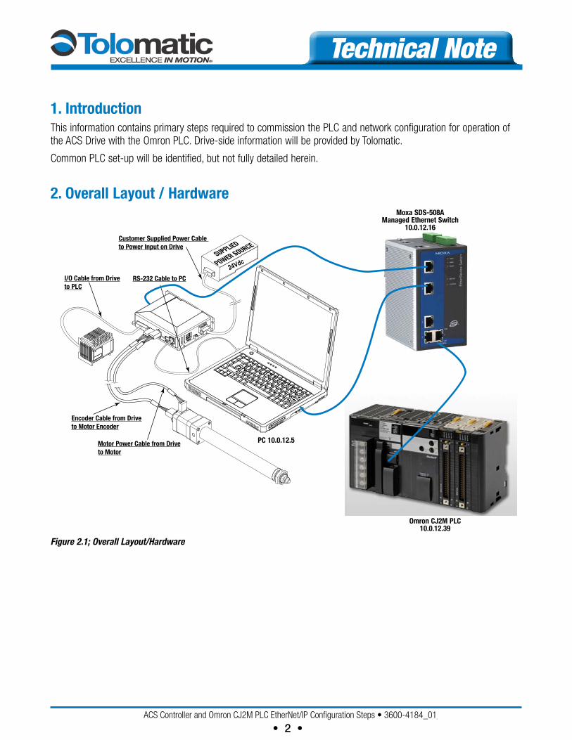
2. Overall Layout / Hardware
SUPPLIED
POWER SOURCE
24Vdc
RS-232 Cable to PC
Customer Supplied Power Cable to Power Input on Drive
I/O Cable from Driveto PLC
Encoder Cable from Driveto Motor Encoder
Motor Power Cable from Driveto Motor
PC 10.0.12.5
Omron CJ2m PLC10.0.12.39
moxa SDS-508Amanaged Ethernet Switch
10.0.12.16
Figure 2.1; Overall Layout/Hardware
ACSControllerandOmronCJ2MPLCEtherNet/IPConfigurationSteps•3600-4184_01_TN_ACS-Omron
• 3 •
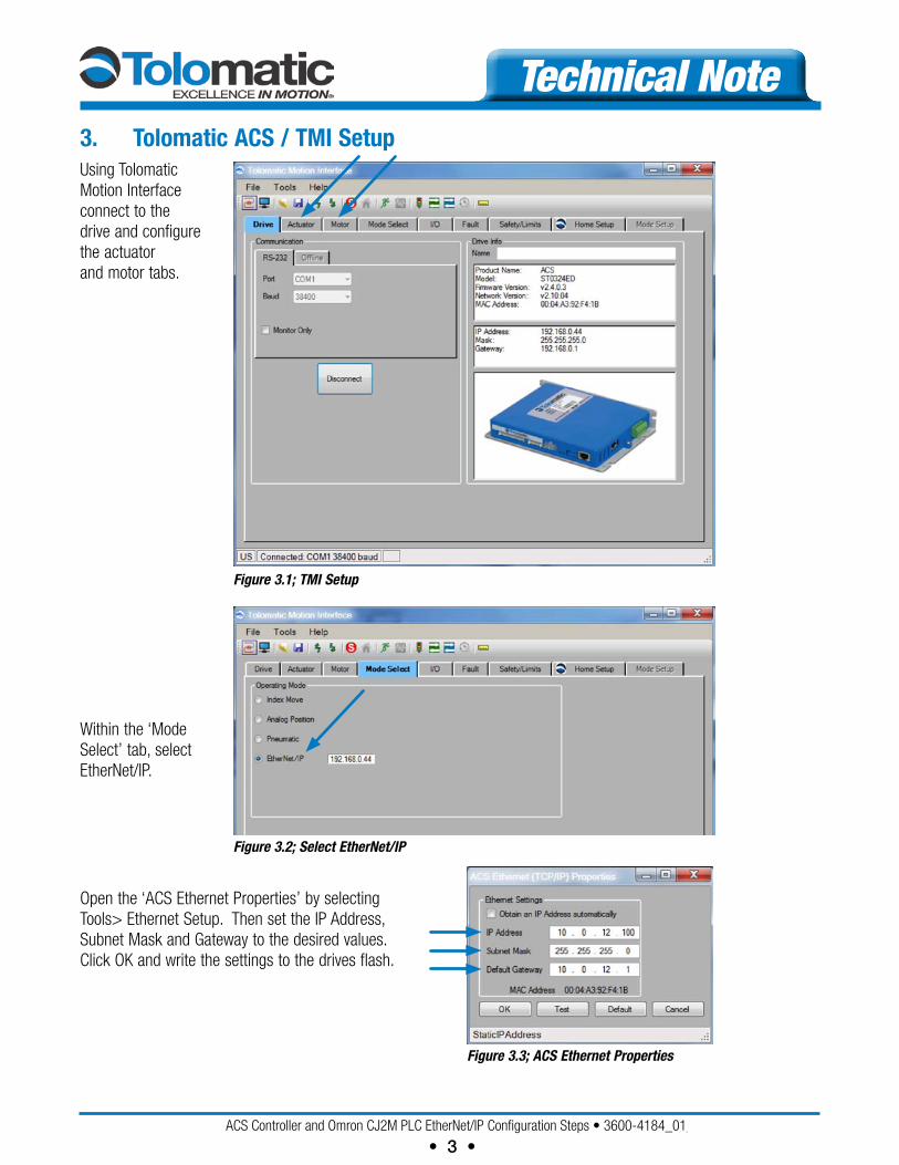
Technical Note3. Tolomatic ACS / TmI SetupUsing Tolomatic Motion Interface connect to the drive and configure the actuator and motor tabs.
Within the ‘Mode Select’ tab, select EtherNet/IP.
Open the ‘ACS Ethernet Properties’ by selecting Tools> Ethernet Setup. Then set the IP Address, Subnet Mask and Gateway to the desired values. Click OK and write the settings to the drives flash.
Figure 3.1; TMI Setup
Figure 3.3; ACS Ethernet Properties
Figure 3.2; Select EtherNet/IP
ACSControllerandOmronCJ2MPLCEtherNet/IPConfigurationSteps•3600-4184_01_TN_ACS-Omron
• 4 •
Technical Note4. Commission PLC A. Set PLC rotary switches as required Ethernet Modules Unit # and Node #
B. Start project and connect via USB com.
C. Register I/O table, set IP address, and Routing Table (if applicable, – if using more than one SIOU card)
D. Download, discon., change comm. to Ethernet
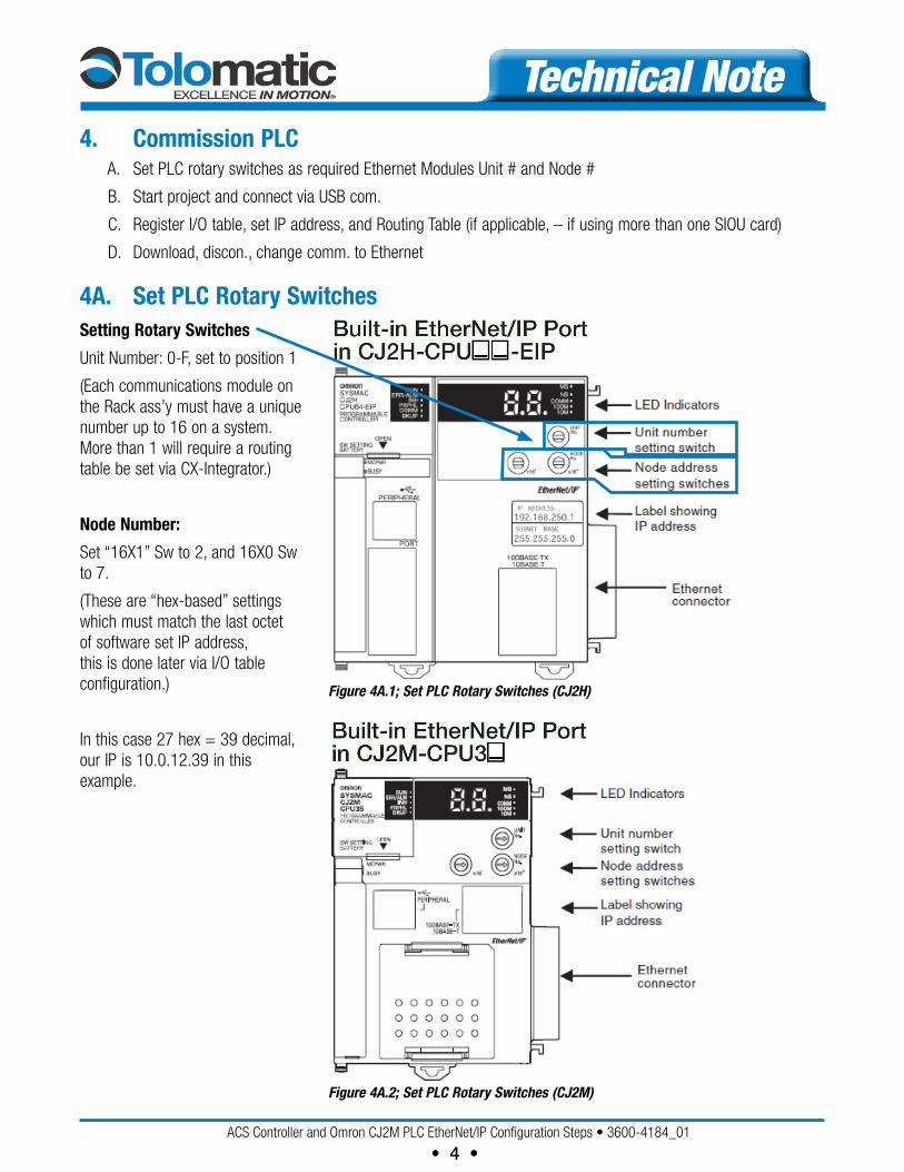
4A. Set PLC rotary Switches
Figure 4A.1; Set PLC Rotary Switches (CJ2H)
Figure 4A.2; Set PLC Rotary Switches (CJ2M)
Setting rotary Switches
Unit Number: 0-F, set to position 1
(Each communications module on the Rack ass’y must have a unique number up to 16 on a system. More than 1 will require a routing table be set via CX-Integrator.)
Node Number:
Set “16X1” Sw to 2, and 16X0 Sw to 7.
(These are “hex-based” settings which must match the last octet of software set IP address, this is done later via I/O table configuration.)
In this case 27 hex = 39 decimal, our IP is 10.0.12.39 in this example.
ACSControllerandOmronCJ2MPLCEtherNet/IPConfigurationSteps•3600-4184_01_TN_ACS-Omron
• 5 •
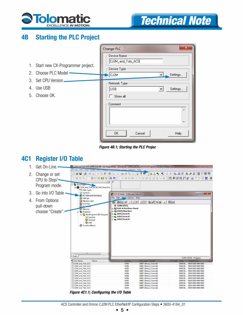
Technical Note4B Starting the PLC Project
1. Start new CX-Programmer project.
2. Choose PLC Model
3. Set CPU Version
4. Use USB
5. Choose OK.
Figure 4B.1; Starting the PLC Projec
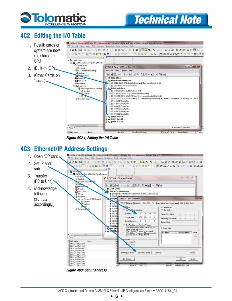
4C1 register I/O Table 1. Get On-Line.
2. Change or set CPU to Stop/Program mode.
3. Go into I/O Table
4. From Options pull-down choose “Create”.
Figure 4C1.1; Configuring the I/O Table
ACSControllerandOmronCJ2MPLCEtherNet/IPConfigurationSteps•3600-4184_01_TN_ACS-Omron
• 6 •
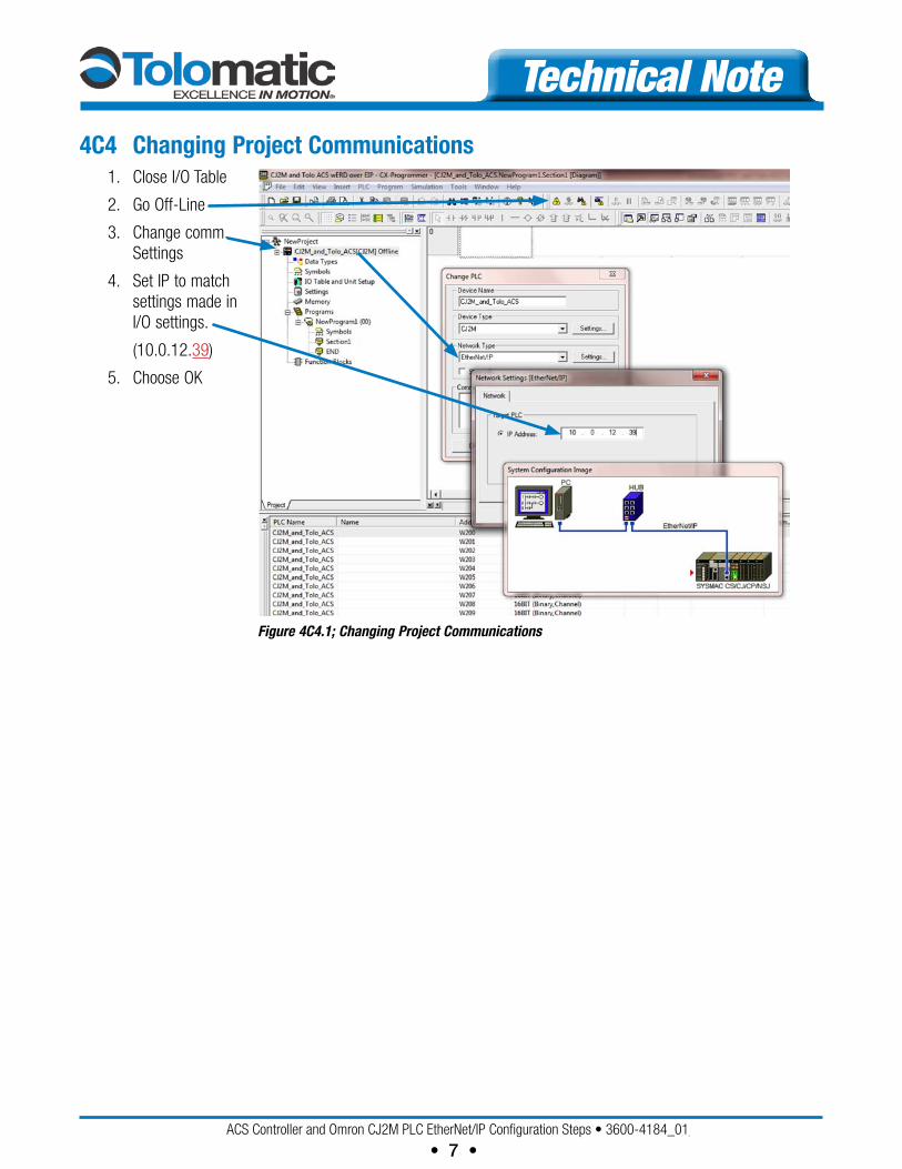
Technical Note4C2 Editing the I/O Table 1. Result: cards on
system are now registered to CPU
2. (Built-in ‘EIP)
3. (Other Cards on “rack”)
{ Figure 4C2.1; Editing the I/O Table
4C3 Ethernet/IP Address Settings 1. Open ‘EIP card
2. Set IP and sub-net.
3. Transfer (PC to Unit)
4. (Acknowledge following prompts accordingly.)
Figure 4C3; Set IP Address
ACSControllerandOmronCJ2MPLCEtherNet/IPConfigurationSteps•3600-4184_01_TN_ACS-Omron
• 7 •
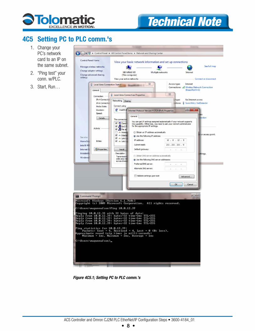
Technical Note4C4 Changing Project Communications 1. Close I/O Table
2. Go Off-Line
3. Change comm. Settings
4. Set IP to match settings made in I/O settings.
(10.0.12.39)
5. Choose OK
Figure 4C4.1; Changing Project Communications
ACSControllerandOmronCJ2MPLCEtherNet/IPConfigurationSteps•3600-4184_01_TN_ACS-Omron
• 8 •
Technical Note4C5 Setting PC to PLC comm.'s 1. Change your
PC’s network card to an IP on the same subnet.
2. “Ping test” your conn. w/PLC.
3. Start, Run…
Figure 4C5.1; Setting PC to PLC comm.'s
ACSControllerandOmronCJ2MPLCEtherNet/IPConfigurationSteps•3600-4184_01_TN_ACS-Omron
• 9 •
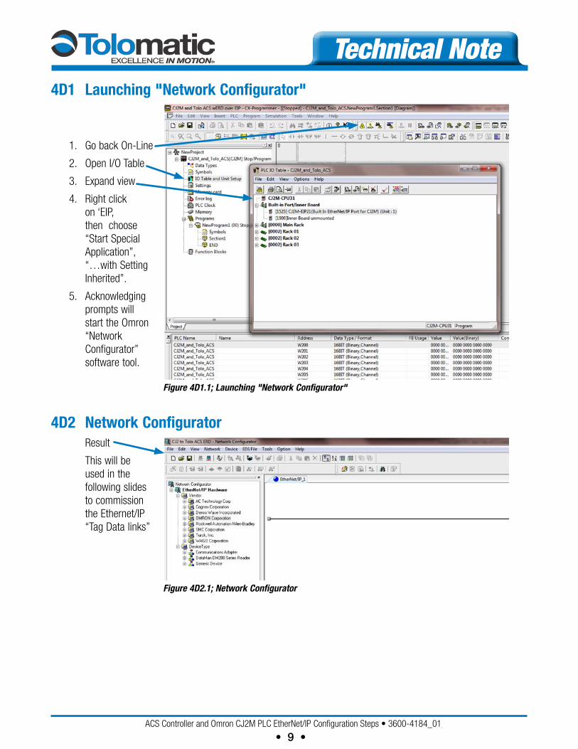
Technical Note4D1 Launching "Network Configurator"
1. Go back On-Line
2. Open I/O Table
3. Expand view
4. Right click on ‘EIP, then choose “Start Special Application”, “…with Setting Inherited”.
5. Acknowledging prompts will start the Omron “Network Configurator” software tool.
Figure 4D1.1; Launching "Network Configurator"
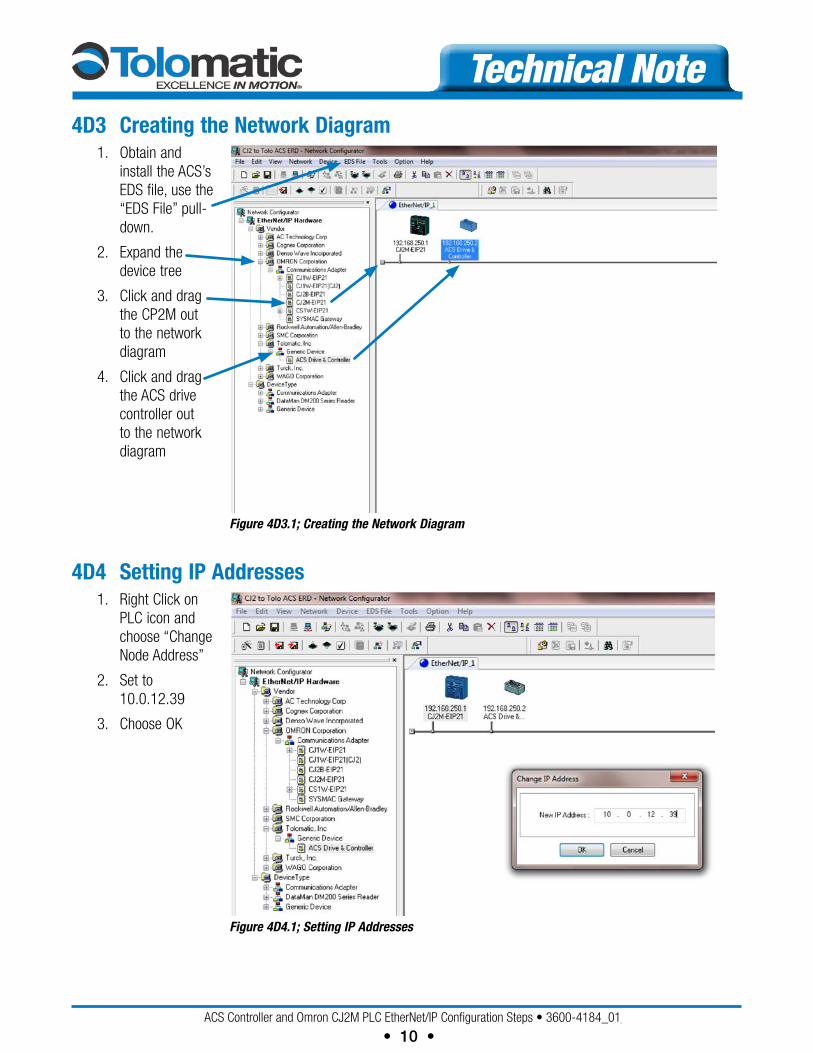
4D2 Network Configurator Result
This will be used in the following slides to commission the Ethernet/IP “Tag Data links”
Figure 4D2.1; Network Configurator
ACSControllerandOmronCJ2MPLCEtherNet/IPConfigurationSteps•3600-4184_01_TN_ACS-Omron
• 10 •
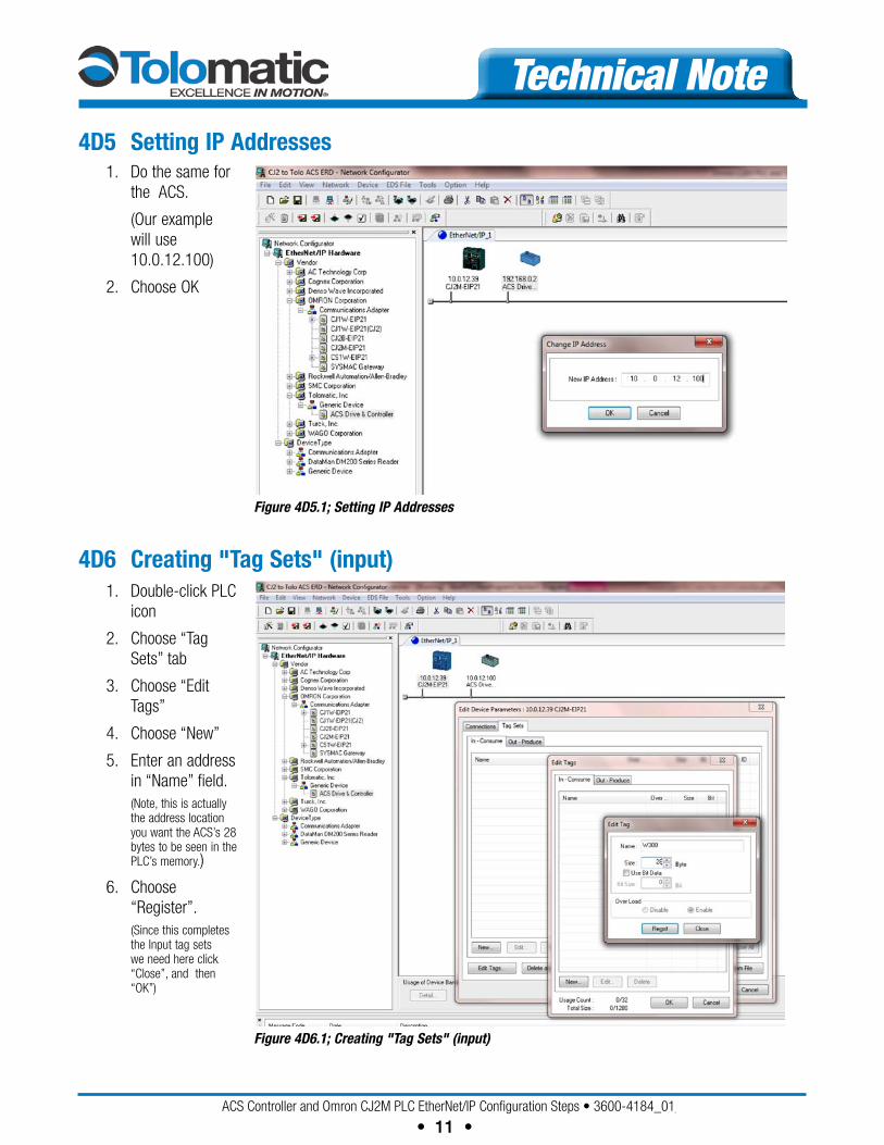
Technical Note4D3 Creating the Network Diagram 1. Obtain and
install the ACS’s EDS file, use the “EDS File” pull-down.
2. Expand the device tree
3. Click and drag the CP2M out to the network diagram
4. Click and drag the ACS drive controller out to the network diagram
Figure 4D3.1; Creating the Network Diagram
4D4 Setting IP Addresses 1. Right Click on
PLC icon and choose “Change Node Address”
2. Set to 10.0.12.39
3. Choose OK
Figure 4D4.1; Setting IP Addresses
ACSControllerandOmronCJ2MPLCEtherNet/IPConfigurationSteps•3600-4184_01_TN_ACS-Omron
• 11 •
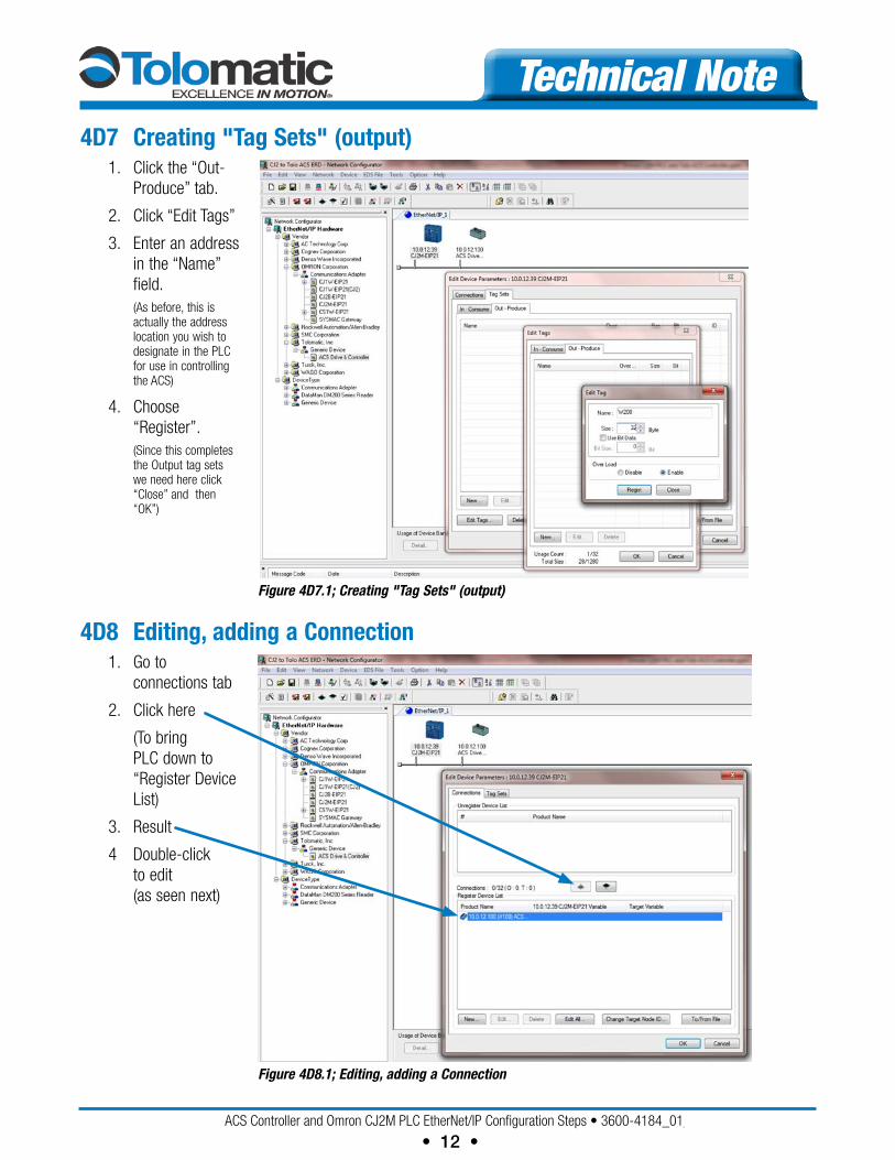
Technical Note4D5 Setting IP Addresses 1. Do the same for
the ACS.
(Our example will use 10.0.12.100)
2. Choose OK
Figure 4D5.1; Setting IP Addresses
4D6 Creating "Tag Sets" (input) 1. Double-click PLC
icon
2. Choose “Tag Sets” tab
3. Choose “Edit Tags”
4. Choose “New”
5. Enter an address in “Name” field.
(Note, this is actually the address location you want the ACS’s 28 bytes to be seen in the PLC’s memory.)
6. Choose “Register”.
(Since this completes the Input tag sets we need here click “Close”, and then “OK”)
Figure 4D6.1; Creating "Tag Sets" (input)
ACSControllerandOmronCJ2MPLCEtherNet/IPConfigurationSteps•3600-4184_01_TN_ACS-Omron
• 12 •
Technical Note4D7 Creating "Tag Sets" (output) 1. Click the “Out-
Produce” tab.
2. Click “Edit Tags”
3. Enter an address in the “Name” field.
(As before, this is actually the address location you wish to designate in the PLC for use in controlling the ACS)
4. Choose “Register”.
(Since this completes the Output tag sets we need here click “Close” and then “OK”)
Figure 4D7.1; Creating "Tag Sets" (output)
4D8 Editing, adding a Connection 1. Go to
connections tab
2. Click here
(To bring PLC down to “Register Device List)
3. Result
4 Double-click to edit (as seen next)
Figure 4D8.1; Editing, adding a Connection
ACSControllerandOmronCJ2MPLCEtherNet/IPConfigurationSteps•3600-4184_01_TN_ACS-Omron
• 13 •
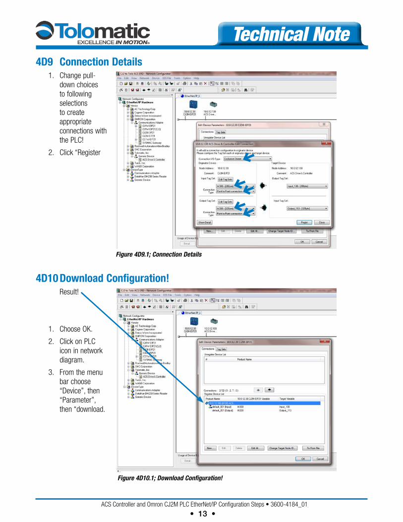
Technical Note4D9 Connection Details 1. Change pull-
down choices to following selections to create appropriate connections with the PLC!
2. Click “Register
Figure 4D9.1; Connection Details
4D10 Download Configuration! Result!
1. Choose OK.
2. Click on PLC icon in network diagram.
3. From the menu bar choose “Device”, then “Parameter”, then “download.
Figure 4D10.1; Download Configuration!
ACSControllerandOmronCJ2MPLCEtherNet/IPConfigurationSteps•3600-4184_01_TN_ACS-Omron
• 14 •
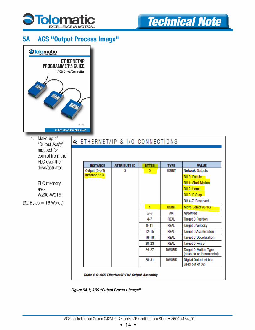
Technical Note5A ACS "Output Process Image"
1. Make up of “Output Ass’y” mapped for control from the PLC over the drive/actuator.
PLC memory area W200-W215
(32 Bytes = 16 Words)
Figure 5A.1; ACS "Output Process Image"
ACSControllerandOmronCJ2MPLCEtherNet/IPConfigurationSteps•3600-4184_01_TN_ACS-Omron
• 15 •
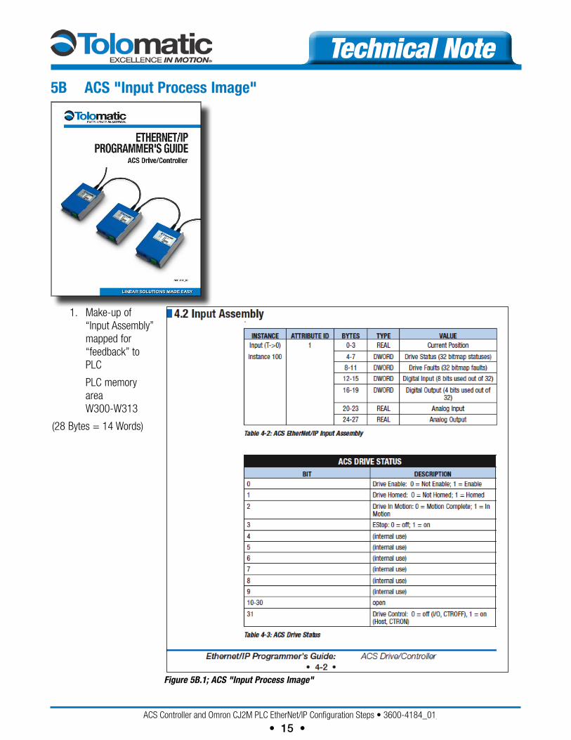
Technical Note5B ACS "Input Process Image"
1. Make-up of “Input Assembly” mapped for “feedback” to PLC
PLC memory area W300-W313
(28 Bytes = 14 Words)
Figure 5B.1; ACS "Input Process Image"
ACSControllerandOmronCJ2MPLCEtherNet/IPConfigurationSteps•3600-4184_01_TN_ACS-Omron
• 16 •
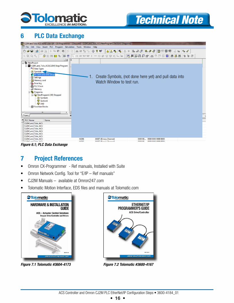
Technical Note6 PLC Data Exchange
1. Create Symbols, (not done here yet) and pull data into Watch Window to test run.
Figure 6.1; PLC Data Exchange
7 Project references• OmronCX-Programmer-Refmanuals,InstalledwithSuite
• OmronNetworkConfig.Toolfor“E/IP–Refmanuals”
• CJ2MManuals–availableatOmron247.com
• TolomaticMotionInterface,EDSfilesandmanualsatTolomatic.com
Figure 7.1 Tolomatic #3604-4173 Figure 7.2 Tolomatic #3600-4167
ACSControllerandOmronCJ2MPLCEtherNet/IPConfigurationSteps•3600-4184_01_TN_ACS-Omron
• 17 •
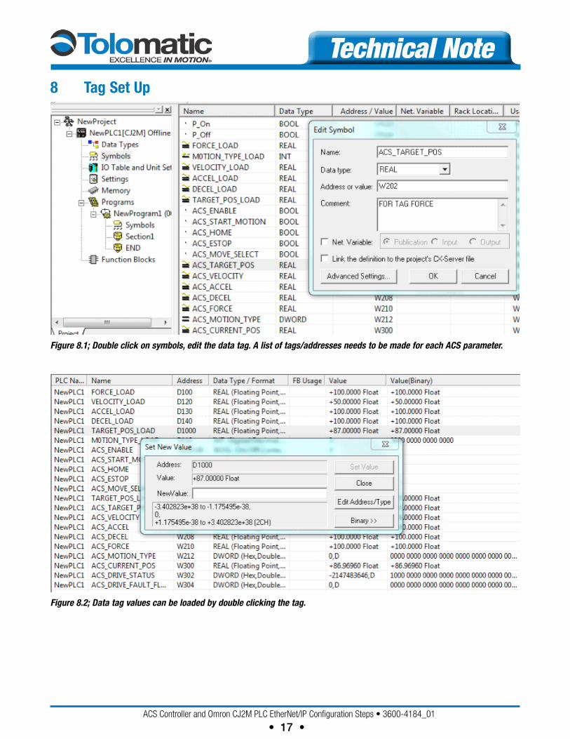
Technical Note8 Tag Set Up
Figure 8.1; Double click on symbols, edit the data tag. A list of tags/addresses needs to be made for each ACS parameter.
Figure 8.2; Data tag values can be loaded by double clicking the tag.
ACSControllerandOmronCJ2MPLCEtherNet/IPConfigurationSteps•3600-4184_01_TN_ACS-Omron
• 18 •
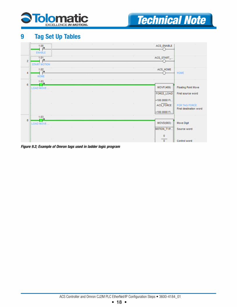
Technical Note9 Tag Set Up Tables
Figure 9.2; Example of Omron tags used in ladder logic program


![[eBook] PLC Beginner Guide (OMRON CPM1A)](https://img.pdfslide.us/doc/110x75/577cc3221a28aba7119530c2/ebook-plc-beginner-guide-omron-cpm1a.jpg)
