Embed Size (px)
Citation preview

ACS 160 Installation andStart-up Guide
LONWORKS® Adapter ModuleCFB-LON


© 200
LONWORKS® Adapter ModuleCFB-LON
Installation andStart-up Guide
3BFE 64421158 R0125
EFFECTIVE: 1.9.2001
1 ABB Industry Oy. All Rights Reserved.


Safety Instructions
Overview This chapter states the safety instructions that must be followed when installing and operating the CFB-LON LONWORKS® Adapter Module.
The material in this chapter must be studied before attempting any work on, or with, the unit.
Warnings and Notes
This manual distinguishes two sorts of safety instructions. Warnings are used to inform of conditions which can, if proper steps are not taken, lead to a serious fault condition, physical injury and death. Notes are used when the reader is required to pay special attention or when there is additional information available on the subject. Notes are less crucial than Warnings, but should not be disregarded.
Warnings Readers are informed of situations that can result in serious physical injury and/or serious damage to equipment with the following symbols:
Dangerous Voltage Warning: warns of situations in which a high voltage can cause physical injury and/or damage equipment. The text next to this symbol describes ways to avoid the danger.
General Warning: warns of situations which can cause physical injury and/or damage equipment by means other than electrical. The text next to this symbol describes ways to avoid the danger.
CFB-LON Installation and Start-up Guide i

Safety Instructions
Notes Readers are notified of the need for special attention or additional information available on the subject with the following symbols:
General Safety Instructions
WARNING! All electrical installation and maintenance work on the drive should be carried out by qualified electricians.
The drive and adjoining equipment must be properly earthed.
Do not attempt any work on a powered drive. After switching off the mains, always allow the intermediate circuit capacitors 5 minutes to discharge before working on the frequency converter, the motor or the motor cable. It is good practice to check (with a voltage indicating instrument) that the drive is in fact discharged before beginning work.
The motor cable terminals of the drive are at a dangerously high voltage when mains power is applied, regardless of motor operation.
There can be dangerous voltages inside the drive from external control circuits even when the drive mains power is shut off. Exercise appropriate care when
Electrostatic Discharge Warning: warns of situations in which an electrostatic discharge can damage equipment. The text next to this symbol describes ways to avoid the danger.
CAUTION! Caution aims to draw special attention to a particular issue.
Note: Note gives additional information or points out more information available on the subject.
ii CFB-LON Installation and Start-up Guide

Safety Instructions
working with the unit. Neglecting these instructions can cause physical injury and death.
WARNING! There are several automatic reset functions in the drive. If selected, they reset the unit and resume operation after a fault. These functions should not be selected if other equipment is not compatible with this kind of operation, or dangerous situations can be caused by such action.
More Warnings and Notes are printed at appropriate instances along the text.
CFB-LON Installation and Start-up Guide iii

Safety Instructions
iv CFB-LON Installation and Start-up Guide
Table of Contents
Safety Instructions
Overview . . . . . . . . . . . . . . . . . . . . . . . . . . . . . . . . . . . . . . . . . . . . . . . . . . . . . . iWarnings and Notes. . . . . . . . . . . . . . . . . . . . . . . . . . . . . . . . . . . . . . . . . . . . . . iGeneral Safety Instructions . . . . . . . . . . . . . . . . . . . . . . . . . . . . . . . . . . . . . . . ii
Table of Contents
Chapter 1 – Introduction to This Guide
Intended Audience . . . . . . . . . . . . . . . . . . . . . . . . . . . . . . . . . . . . . . . . . . . . 1-1Compatibility. . . . . . . . . . . . . . . . . . . . . . . . . . . . . . . . . . . . . . . . . . . . . . . . . 1-1Before You Start. . . . . . . . . . . . . . . . . . . . . . . . . . . . . . . . . . . . . . . . . . . . . . 1-1What This Guide Contains . . . . . . . . . . . . . . . . . . . . . . . . . . . . . . . . . . . . . . 1-1Terms and Abbreviations . . . . . . . . . . . . . . . . . . . . . . . . . . . . . . . . . . . . . . . 1-2Further Information. . . . . . . . . . . . . . . . . . . . . . . . . . . . . . . . . . . . . . . . . . . . 1-3
Chapter 2 – Overview
Overview . . . . . . . . . . . . . . . . . . . . . . . . . . . . . . . . . . . . . . . . . . . . . . . . . . . 2-1The LONWORKS® System . . . . . . . . . . . . . . . . . . . . . . . . . . . . . . . . . . . . . . . 2-1The CFB-LON Module . . . . . . . . . . . . . . . . . . . . . . . . . . . . . . . . . . . . . . . . . 2-2
Delivery Check . . . . . . . . . . . . . . . . . . . . . . . . . . . . . . . . . . . . . . . . . . . . . 2-3Warranty and Liability Information . . . . . . . . . . . . . . . . . . . . . . . . . . . . . . 2-4
Chapter 3 – Installation
Exploded View of the CFB-LON. . . . . . . . . . . . . . . . . . . . . . . . . . . . . . . . . . 3-1Mounting . . . . . . . . . . . . . . . . . . . . . . . . . . . . . . . . . . . . . . . . . . . . . . . . . . . 3-2Drive Connection . . . . . . . . . . . . . . . . . . . . . . . . . . . . . . . . . . . . . . . . . . . . . 3-2The LONWORKS® Connection . . . . . . . . . . . . . . . . . . . . . . . . . . . . . . . . . . . . 3-2
Bus Termination . . . . . . . . . . . . . . . . . . . . . . . . . . . . . . . . . . . . . . . . . . . . 3-2Procedure . . . . . . . . . . . . . . . . . . . . . . . . . . . . . . . . . . . . . . . . . . . . . . . . . 3-3
CFB-LON Installation and Start-up Guide v

Table of Contents
Chapter 4 – Programming
Overview . . . . . . . . . . . . . . . . . . . . . . . . . . . . . . . . . . . . . . . . . . . . . . . . . . . . 4-1Configuring the Drive . . . . . . . . . . . . . . . . . . . . . . . . . . . . . . . . . . . . . . . . . . 4-2Configuring the Network . . . . . . . . . . . . . . . . . . . . . . . . . . . . . . . . . . . . . . . . 4-4
Resource Files . . . . . . . . . . . . . . . . . . . . . . . . . . . . . . . . . . . . . . . . . . . . . 4-4
Chapter 5 – Communication
Overview . . . . . . . . . . . . . . . . . . . . . . . . . . . . . . . . . . . . . . . . . . . . . . . . . . . . 5-1General . . . . . . . . . . . . . . . . . . . . . . . . . . . . . . . . . . . . . . . . . . . . . . . . . . . . . 5-1CFB-LON Object Diagram . . . . . . . . . . . . . . . . . . . . . . . . . . . . . . . . . . . . . . 5-1
Chapter 6 – Status LEDs
Status LEDs . . . . . . . . . . . . . . . . . . . . . . . . . . . . . . . . . . . . . . . . . . . . . . . . . 6-1
Appendix A – List of Network Variables
Input Network Variables (nvi’s) . . . . . . . . . . . . . . . . . . . . . . . . . . . . . . . . . . . A-1nviObjRequest. . . . . . . . . . . . . . . . . . . . . . . . . . . . . . . . . . . . . . . . . . . . . . A-1nviSpeedStpt . . . . . . . . . . . . . . . . . . . . . . . . . . . . . . . . . . . . . . . . . . . . . . . A-1nviDrvSpeedScale. . . . . . . . . . . . . . . . . . . . . . . . . . . . . . . . . . . . . . . . . . . A-2nviResetFault . . . . . . . . . . . . . . . . . . . . . . . . . . . . . . . . . . . . . . . . . . . . . . A-2nviSerialData1, nviSerialData2, nviSerialData3 . . . . . . . . . . . . . . . . . . . . A-3
Output Network Variables . . . . . . . . . . . . . . . . . . . . . . . . . . . . . . . . . . . . . . . A-3nvoObjStatus. . . . . . . . . . . . . . . . . . . . . . . . . . . . . . . . . . . . . . . . . . . . . . . A-3nvoDrvCurnt . . . . . . . . . . . . . . . . . . . . . . . . . . . . . . . . . . . . . . . . . . . . . . . A-4nvoDrvSpeed. . . . . . . . . . . . . . . . . . . . . . . . . . . . . . . . . . . . . . . . . . . . . . . A-4nvoDrvStatus. . . . . . . . . . . . . . . . . . . . . . . . . . . . . . . . . . . . . . . . . . . . . . . A-4nvoRunning . . . . . . . . . . . . . . . . . . . . . . . . . . . . . . . . . . . . . . . . . . . . . . . . A-4nvoFaulted. . . . . . . . . . . . . . . . . . . . . . . . . . . . . . . . . . . . . . . . . . . . . . . . . A-4nvoCtrlLoc . . . . . . . . . . . . . . . . . . . . . . . . . . . . . . . . . . . . . . . . . . . . . . . . . A-5nvoDrvPwr. . . . . . . . . . . . . . . . . . . . . . . . . . . . . . . . . . . . . . . . . . . . . . . . . A-5nvoDrvEnrgy . . . . . . . . . . . . . . . . . . . . . . . . . . . . . . . . . . . . . . . . . . . . . . . A-5nvoFreqAct . . . . . . . . . . . . . . . . . . . . . . . . . . . . . . . . . . . . . . . . . . . . . . . . A-5nvoSpeedActRpm . . . . . . . . . . . . . . . . . . . . . . . . . . . . . . . . . . . . . . . . . . . A-5nvoTorqAct . . . . . . . . . . . . . . . . . . . . . . . . . . . . . . . . . . . . . . . . . . . . . . . . A-5nvoDrvTemp . . . . . . . . . . . . . . . . . . . . . . . . . . . . . . . . . . . . . . . . . . . . . . . A-5nvoDrvRunHours. . . . . . . . . . . . . . . . . . . . . . . . . . . . . . . . . . . . . . . . . . . . A-6nvoPidAct1 . . . . . . . . . . . . . . . . . . . . . . . . . . . . . . . . . . . . . . . . . . . . . . . . A-6
vi CFB-LON Installation and Start-up Guide
Table of Contents
nvoPidAct2 . . . . . . . . . . . . . . . . . . . . . . . . . . . . . . . . . . . . . . . . . . . . . . . . A-6nvoDcBusVolt . . . . . . . . . . . . . . . . . . . . . . . . . . . . . . . . . . . . . . . . . . . . . . A-6nvoFault1, nvoFault2, nvoFault3 . . . . . . . . . . . . . . . . . . . . . . . . . . . . . . . A-6nvoParValue . . . . . . . . . . . . . . . . . . . . . . . . . . . . . . . . . . . . . . . . . . . . . . . A-6nvoDigInput1 to nvoDigInput5 . . . . . . . . . . . . . . . . . . . . . . . . . . . . . . . . . A-7nvoDigOutput1, nvoDigOutput2 . . . . . . . . . . . . . . . . . . . . . . . . . . . . . . . . A-7
Configuration Network Variables . . . . . . . . . . . . . . . . . . . . . . . . . . . . . . . . . A-7nciSndHrtBt . . . . . . . . . . . . . . . . . . . . . . . . . . . . . . . . . . . . . . . . . . . . . . . A-7nciRcvHrtBt. . . . . . . . . . . . . . . . . . . . . . . . . . . . . . . . . . . . . . . . . . . . . . . . A-8nciMinOutTm . . . . . . . . . . . . . . . . . . . . . . . . . . . . . . . . . . . . . . . . . . . . . . A-8nciLocation . . . . . . . . . . . . . . . . . . . . . . . . . . . . . . . . . . . . . . . . . . . . . . . . A-8nciNmlSpeed . . . . . . . . . . . . . . . . . . . . . . . . . . . . . . . . . . . . . . . . . . . . . . A-9nciNmlFreq . . . . . . . . . . . . . . . . . . . . . . . . . . . . . . . . . . . . . . . . . . . . . . . . A-9nciMinSpeed. . . . . . . . . . . . . . . . . . . . . . . . . . . . . . . . . . . . . . . . . . . . . . . A-9nciMaxSpeed . . . . . . . . . . . . . . . . . . . . . . . . . . . . . . . . . . . . . . . . . . . . . A-10nciRampUpTm . . . . . . . . . . . . . . . . . . . . . . . . . . . . . . . . . . . . . . . . . . . . A-10nciRampDownTm. . . . . . . . . . . . . . . . . . . . . . . . . . . . . . . . . . . . . . . . . . A-10nciCurrLimit . . . . . . . . . . . . . . . . . . . . . . . . . . . . . . . . . . . . . . . . . . . . . . A-10nciPidGain . . . . . . . . . . . . . . . . . . . . . . . . . . . . . . . . . . . . . . . . . . . . . . . A-11nciPidTime . . . . . . . . . . . . . . . . . . . . . . . . . . . . . . . . . . . . . . . . . . . . . . . A-11nciPidDerTime . . . . . . . . . . . . . . . . . . . . . . . . . . . . . . . . . . . . . . . . . . . . A-11nciPidMacroSel. . . . . . . . . . . . . . . . . . . . . . . . . . . . . . . . . . . . . . . . . . . . A-11nciDrvSpeedScale . . . . . . . . . . . . . . . . . . . . . . . . . . . . . . . . . . . . . . . . . A-12nciStopMode. . . . . . . . . . . . . . . . . . . . . . . . . . . . . . . . . . . . . . . . . . . . . . A-12nciStopLevel . . . . . . . . . . . . . . . . . . . . . . . . . . . . . . . . . . . . . . . . . . . . . . A-12nciExt1Ext2Sel . . . . . . . . . . . . . . . . . . . . . . . . . . . . . . . . . . . . . . . . . . . . A-12nciParValue . . . . . . . . . . . . . . . . . . . . . . . . . . . . . . . . . . . . . . . . . . . . . . A-13nciParRead. . . . . . . . . . . . . . . . . . . . . . . . . . . . . . . . . . . . . . . . . . . . . . . A-13nciParWrite . . . . . . . . . . . . . . . . . . . . . . . . . . . . . . . . . . . . . . . . . . . . . . . A-13
Fault Codes . . . . . . . . . . . . . . . . . . . . . . . . . . . . . . . . . . . . . . . . . . . . . . . . A-13
Appendix B – Technical Data
LONWORKS® Network . . . . . . . . . . . . . . . . . . . . . . . . . . . . . . . . . . . . . . . . . . B-1CFB-LON . . . . . . . . . . . . . . . . . . . . . . . . . . . . . . . . . . . . . . . . . . . . . . . . . . . B-4
Appendix C – Ambient Conditions
Operation . . . . . . . . . . . . . . . . . . . . . . . . . . . . . . . . . . . . . . . . . . . . . . . . . . . C-1Storage and Transportation . . . . . . . . . . . . . . . . . . . . . . . . . . . . . . . . . . . . . C-1
CFB-LON Installation and Start-up Guide vii

Table of Contents
viii CFB-LON Installation and Start-up Guide

Chapter 1 – Introduction to This Guide
Intended Audience
The Guide is intended for the people who are responsible for commissioning and using a CFB-LON LONWORKS® Adapter Module with the ACS 160 drive. The reader is expected to have a basic knowledge of
• electrical fundamentals and wiring practices
• the drive and its control panel
• the host controller software.
Compatibility This manual is compatible with ACS 160 software version 1.0.0.0 or later, and CFB-LON module version A or later.
Before You Start It is assumed that the drive is installed and ready to operate before starting the installation of the adapter module.
In addition to conventional installation tools, have the drive manuals available during the installation as they contain important information not included in this guide. The drive manuals are referred to at various points of this guide.
What This Guide Contains
This manual contains information on the wiring, configuration and use of the CFB-LON module.
Safety Instructions are featured in the first few pages of this Guide. Safety Instructions describe the formats for various warnings and notations used within this Guide.
Chapter 2 – Overview contains a short description of the LONWORKS® system and the CFB-LON LONWORKS®
CFB-LON Installation and Start-up Guide 1-1

Chapter 1 – Introduction to This Guide
Adapter Module, a delivery checklist, and warranty information.
Chapter 3 – Installation contains wiring instructions.
Chapter 4 – Programming explains how to program the master station and the drive before the communication through the adapter module can be started.
Chapter 5 – Communication contains a description of how data is transmitted through the CFB-LON and information about resource files.
Chapter 6 – Status LEDs explains the status LED indications of the CFB-LON module.
Appendix A lists the Network Variables.
Appendix B contains Technical Data.
Appendix C contains a specification of the ambient conditions allowed during transportation, storage and use of the CFB-LON module.
Terms and Abbreviations
Functional Profile Functional profiles may contain one or more objects that interact to perform the required profile defined operability. The Variable Speed Motor Drive Profile contains the general LONMARK® Node Object and the application-specific Variable Speed Motor Drive Object.
LonMark® Products that conform to LONMARK® Interoperability Guidelines, defined by the LONMARK® Interoperability Association, are eligible to carry the LONMARK® logo.
LonTalk® The communication protocol in LONWORKS® networks.
nci Configuration property.
1-2 CFB-LON Installation and Start-up Guide

Chapter 1 – Introduction to This Guide
Neuron® ID Every LONWORKS® device or – as synonym – node must have a unique ID. This is called the Neuron® ID. This ID is, on Neuron® Chip-based nodes, stored in the chip itself and cannot be changed.
nv Network variable.
nvi Input network variable.
nvo Output network variable.
Object Object is a set of one or more network variables implemented as SNVTs with semantic definitions relating the behaviour of the object to the network variable values, in addition to a set of configuration properties. For example, the Variable Speed Motor Drive Object and the Node Object represent two types of objects.
Parameter A parameter is an operating instruction for the drive. Parameters can be read and programmed with the drive control panel, or through the CFB-LON Module.
Service Pin The Service Pin is used in installing the node. Pressing the Service Pin causes the node to send a so-called Service Pin Message which includes, among other things, the Neuron® ID. This informs the nertwork or installation tool about the node.
There is a Service Pin pushbutton on the CFB-LON circuit board. It is also possible to connect an external pushbutton to the terminal block of the CFB-LON. See Chapter 3.
SNVT Standard Network Variable Type.
Further Information
Further information is available on the WWW from www.lonmark.org and www.echelon.com.
CFB-LON Installation and Start-up Guide 1-3

Chapter 1 – Introduction to This Guide
1-4 CFB-LON Installation and Start-up Guide

Chapter 2 – Overview
Overview This chapter contains a short description of the LONWORKS® system and the CFB-LON module, a delivery checklist, and warranty information.
The LONWORKS® System
The LONWORKS® system is an open communication solution that enables data exchange between all kinds of automation components.
A LONWORKS® network consists of intelligent devices, called nodes, connected by one or more communications media that communicate with one another using the LonTalk® protocol. Nodes are programmed to send messages to one another in response to external events or messages they receive. Each intelligent device, for example a programmable thermostat in a building control system, is a LONWORKS® node. A node is connected to other nodes with appropriate communications media, such as twisted pair cable, RF link, or power line circuit.
LONWORKS® nodes are objects that respond to various inputs and that produce desired outputs. Connecting the inputs and outputs of these network objects enables the network to perform specific tasks.
While the function of any particular node may be quite simple, the interaction among nodes enables a LONWORKS® network to perform complex tasks. A benefit of LONWORKS® networks is that a small number of common node types may perform a broad spectrum of different functions depending on how they are configured and connected.
CFB-LON Installation and Start-up Guide 2-1

Chapter 2 – Overview
The CFB-LON Module
The CFB-LON LONWORKS® Adapter Module is an optional device which enables the connection of an ACS 160 drive to a LONWORKS® network.
Figure 2-1 The construction of a LONWORKS® network.
ACS 160
LONWORKS® nodes
ACS 160
CFB-LON
2-2 CFB-LON Installation and Start-up Guide

Chapter 2 – Overview
Through the CFB-LON, it is possible to:
• Give control commands to the drive(Start, Stop, Run enable, etc.)
• Feed a motor speed reference to the drive
• Read status information and actual values from the drive
• Change drive parameter values
• Reset a drive fault.
The network variables and functions supported by the CFB-LON LONWORKS® Adapter Module are discussed in Chapter 5.
The adapter module is mounted onto the side of the ACS 160 drive. See the ACS 160 User’s Manual for more information.
Delivery Check The option package of the CFB-LON LONWORKS® Adapter Module contains:
• LONWORKS® Adapter Module, Type CFB-LON
• 2 pcs M16×1.5 cable glands with O ring
• 2 pcs M4×12 mounting screws
• this manual, the CFB-LON Installation and Start-up Guide.
CFB-LON Installation and Start-up Guide 2-3

Chapter 2 – Overview
Warranty andLiability
Information
The warranty for your ABB drive and options covers manufacturing defects. The manufacturer carries no responsibility for damage due to transport or unpacking.
In no event and under no circumstances shall the manufacturer be liable for damages and failures due to misuse, abuse, improper installation, or abnormal conditions of temperature, dust, or corrosives, or failures due to operation above rated capacities. Nor shall the manufacturer ever be liable for consequential and incidental damages.
The period of manufacturer's warranty is 12 months, and not more than 18 months, from the date of delivery. Extended warranty may be available with certified start-up. Contact your local distributor for details.
Your local ABB Drives company or distributor may have a different warranty period, which is specified in their sales terms, conditions, and warranty terms.
If you have any questions concerning your ABB drive, contact your local distributor or ABB Drives office.
The technical data and specifications are valid at the time of printing. ABB reserves the right to subsequent alterations.
2-4 CFB-LON Installation and Start-up Guide

Chapter 3 – Installation
WARNING! Follow the safety instructions given in this Guide and in the ACS 160 User’s Manual.
WARNING! The CFB-LON contains components sensitive to electrostatic discharge (ESD). Wear an earthing wrist band when handling the circuit board assembly. Do not touch the boards unnecessarily.
Exploded View of the CFB-LON
Circuit BoardAssembly
MountingScrews (2 pcs)
CoverScrews(4 pcs)
Cable Glandsfor Bus Cables
Cover
(2 pcs)
Drive ConnectionCable
Base
Terminal Blockfor LONWORKS®
Connection
CFB-LON Installation and Start-up Guide 3-1

Chapter 3 – Installation
Mounting The CFB-LON is to be mounted onto the ACS 160 drive with two screws as shown in the ACS 160 User’s Manual. This also provides the earthing of the module housing.
Drive Connection The CFB-LON uses the control panel connector of the drive. (However, leave the CFB-LON disconnected at this point since the control panel is needed later for setting up the communication parameters.)
The CFB-LON is powered through the drive control panel connector.
The LONWORKS® Connection
The CFB-LON provides a cable entry for the LONWORKS® cable. The cables are connected to a detachable terminal header, which enables the disconnection of the CFB-LON without interrupting the data transfer to other devices.
Note: LONWORKS® networks require special cable. It is recommended to use cables defined by LONMARK® Layer 1 – 6 Guidelines. See Appendix B.
Bus Termination The bus must be terminated according to the topology as follows:
Star topologyBus topology Ring topology
FREE
NC
NC
NC
NC
BUS BUSNC NC
FREE
NC
NC
NC
NC
3-2 CFB-LON Installation and Start-up Guide

Chapter 3 – Installation
Procedure To connect the LONWORKS® cables, follow this procedure:
1. Lead the bus cables to the space where the ACS 160 and the CFB-LON are installed in. Arrange the bus cables as far away from any power cables as possible. Avoid parallel runs. Use grommets or cable glands at all cable lead-throughs for protection.
2. Remove the cover of the CFB-LON module. Fasten the cable glands to the cover (if not done already).
3. Lead the bus cables through the cable glands and the cover. Loosen the clamping nuts of the cable glands if necessary.
4. Detach the terminal header from its receptacle on the circuit board assembly and make the connections. (Also install the termination resistors if required at this particular node. See section Bus Termination above.) The diagram below shows two CFB-LON modules in a bus-topology LONWORKS® network.
Description
BUS 105 ohm resistor between data lines A and B at nodes at each end of bus
NC No termination
FREE 52.5 ohm resistor�between data lines A and B at one node in a bus segment
CFB-LON Installation and Start-up Guide 3-3

Chapter 3 – Installation
5. Re-insert the terminal header into its receptacle.
6. Configure and initialise the module according to the instructions in Chapter 4.
7. Replace the cover of the CFB-LON.
8. Tighten the clamping nuts of the cable glands.
A
B
GND
1 2 3 4
BA A
B
5 1 2 3 4 5
1 2 3 4 5
Other LONWORKS®
node (with internal termination)
Bus Connector Terminal Designations
Terminal Description
1 SHIELD Cable screen
2 GND Ground
3 Service Pin For connecting a remote Service Pin pushbutton
4 Net BNetwork cable connection
5 Net A
RemoteService Pinpushbutton
On-board Service Pin
1 2 3 4 5
CFB-LON CFB-LON
105 ohm
105 ohm
3-4 CFB-LON Installation and Start-up Guide

Chapter 4 – Programming
Overview This chapter gives information on configuring the drive for operation with the LONWORKS® Adapter module.
The recommended sequence is as follows:
1. Set the parameters given in Table 4-7. (See section Configuring the Drive below).
2. Power down the drive, disconnect the control panel, and plug in the CFB-LON.
3. Make the network configuration using a network installation tool. (See section Configuring the Network below).
4. Power down the drive, disconnect the CFB-LON, and plug in the control panel.
5. Set the CFB-LON communication parameters given in Table 4-8.
6. Power down the drive, disconnect the control panel, plug in the CFB-LON, and power up the drive.
CFB-LON Installation and Start-up Guide 4-1

Chapter 4 – Programming
Configuring the Drive
It is preferable to configure the drive before the CFB-LON is configured for the network. The reason for this is that the CFB-LON reads several parameter values from the drive in order to operate correctly and in order to select different modes. Furthermore, some of the configuration network variable values receive their defaults from the drive. The drive control location parameters should also be set accordingly to enable full and logical operation of the CFB-LON.
The following table lists the drive parameters utilised by the CFB-LON. The recommended settings and their functions are also covered.
Table 4-7 The drive parameters utilised by the CFB-LON.
Parameter Recommended Setting Function
9902 APPLICATION MACRO*
Set to 6 PID-CONTROL if corresponding network variables are to be used
Enables the updates of nciPidGain, nciPidTime and nciPidDerTime
9907 MOTOR NOM FREQ*
Motor nominal frequency
Initialises the nciNmlFreq value
9908 MOTOR NOM SPEED*
Motor nominal speed Initialises the nciNmlSpeed value
1001 EXT1 COMMANDS
10 COMM Enables CFB-LON control
1002 EXT2 COMMANDS
10 COMM Enables CFB-LON control
1003 DIRECTION 3 REQUEST If direction change is required
1102 EXT1/EXT2 SEL 8 COMM Enables the use of nciExt1Ext2Sel which selects between nviSpeedStpt and nviRefStpt.
1103 EXT REF1 SELECT
8 COMM Enables CFB-LON reference
4-2 CFB-LON Installation and Start-up Guide

Chapter 4 – Programming
*If one of the drive parameter values marked with * not using the corresponding configuration network variable is changed, the CFB-LON needs to be re-initialised in order to update the value to it. For example, if the panel lock parameter is changed with the control panel, the CFB-LON needs to be either rebooted or temporarily disabled for the CFB-LON to read the updated value from the drive. The same applies if one of the marked parameters using the dataset input nvi or the nciParValue configuration parameter is changed.
1105 EXT REF1 MAX Motor nominal frequency
This value corresponds to nviSpeedStpt value 100% (of nominal speed or frequency)
1106 EXT REF2 SELECT
8 COMM Enables CFB-LON reference
1108 EXT REF2 MAX 100% This value corresponds to nviRefStpt value 100%
1501 AO CONTENT — Determines correct speed feedback in nvoDrvSpeed and nvoDrcSpeedActRpm
1601 RUN ENABLE 6 COMM Run enable from CFB-LON
1604 FAULT RESET SEL
7 COMM Enables CFB-LON fault reset
1605 LOCAL LOCK* 1 LOCKED Initialises nciPanelLock value
2007 MINIMUM FREQ* Minimum frequency value
Initialises nciMinSpeed value
2008 MAXIMUM FREQ*
Maximum frequency value
Initialises nciMinSpeed value
4001 PID GAIN* PID gain Initialises nciPidGain value
4002 PID INTEG TIME* PID integration time Initialises nciPidTime value
4003 PID DERIV TIME* PID derivation time Initialises nciPidDerTime value
Parameter Recommended Setting Function
CFB-LON Installation and Start-up Guide 4-3

Chapter 4 – Programming
Table 4-8 The CFB-LON configuration parameters.
Configuring the Network
The CFB-LON cannot communicate with the drive before it is configured for the LONWORKS® network. The LONWORKS® communication configuration does not require parametrisation of the drive. The LONWORKS® network is configured using a network installation tool. Please refer to the installation tool documentation for network configuration.
Resource Files For the installation of the CFB-LON with different installation tools, different resource files are needed. If you have not received these files together with the CFB-LON, please consult your local ABB representative.
Parameter No.
Parameter Name
Settings
5101 Module Type0 None; …; 7 CFB-LON; …; 9 Other
This parameter must be set to 7.
4-4 CFB-LON Installation and Start-up Guide
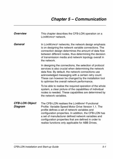
Chapter 5 – Communication
Overview This chapter describes the CFB-LON operation on a LONWORKS® network.
General In LONWORKS® networks, the network design emphasis is on designing the network variable connections. The connection design determines the amount of data flow between different nodes, thus determining the decision of transmission media and network topology overall in the network.
In designing the connections, the selection of protocol services is also crucial when determining the network data flow. By default, the network connections use acknowledged messaging with a certain retry count. These can however be changed by the installation tool to optimise the overall network performance.
To be able to realise the required operation of the whole system, a clear picture of the capabilities of individual nodes is needed. These capabilities are determined by the network variables.
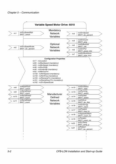
CFB-LON Object Diagram
The CFB-LON realises the LONMARK® Functional Profile: Variable Speed Motor Drive Version 1.1. The profile defines a set of network variables and configuration properties. In addition, the CFB-LON has a set of manufacturer defined network variables and configuration properties that are defined in order to realise functions only applicable for ABB Drives.
CFB-LON Installation and Start-up Guide 5-1
Chapter 5 – Communication
Variable Speed Motor Drive: 6010
MandatoryNetworkVariables
nv1 nviDrvSpeedStptSNVT_switch
OptionalNetworkVariables
Configuration Propertiesnc17 - nciLocationnc50 - nciMaxSpeed (mandatory)nc53 - nciMinSpeed (mandatory)nc48 - nciRcvHrtBtnc49 - nciSndHrtBt (mandatory)nc52 - nciMinOutTmnc158 - nciNmlSpeed (mandatory)nc159 - nciNmlFreq (mandatory)nc160 - nciRampUpTm (mandatory)nc161 - nciRampDownTm (mandatory)nc162 - nciDrvSpeedScale
nv4 nvoDrvSpeed SNVT_lev_percent
nv2 nviDrvSpeedScaleSNVT_lev_percent
nv3 nvoDrvCurntSNVT_amp
nv5 nvoDcBusVoltSNVT_volt
nv6 nvoDrvPwrSNVT_power_kilo
nv7 nvoDrvRunHoursSNVT_time_hour
nv8 nviResetFaultSNVT_switch
nv9 nviSerialData1SNVT_count
nv10 nviSerialData2SNVT_count
nv18 nviSpeedActRpmSNVT_count_inc
nv11 nviSerialData3SNVT_count
nv19 nviTorqActSNVT_count_inc
nv12 nvoDrvStatusSNVT_state
nv13 nvoRunningSNVT_switch
nv14 nvoFaultedSNVT_switch
nv16 nvoDrvEnrgySNVT_count
nv15 nvoCtrlLocSNVT_lev_disc
nv17 nvoFreqActSNVT_freq_hz
ManufacturerDefinedNetworkVariables
nv20 nviDrvTempSNVT_temp_p
nv21 nviPidAct1SNVT_lev_percent
5-2 CFB-LON Installation and Start-up Guide

Chapter 5 – Communication
Figure 6-1 The CFB-LON object diagram.
CFB-LON NetworkVariables
A detailed description of all the CFB-LON network variables and configuration properties is given in Appendix A.
nv22 nvoPidAct2SNVT_lev_percent
nv24 nvoFault2SNVT_count
nv26 nvoParValueSNVT_count_inc
nv30 nvoDigInput4SNVT_switch
nv28 nvoDigInput2SNVT_switch
nv32 nvoDigOutput1SNVT_switch
nv23 nvoFault1SNVT_count
nv25 nvoFault3SNVT_count
nv27 nvoDigInput1SNVT_switch
nv31 nvoDigInput5SNVT_switch
nv29 nvoDigInput3SNVT_switch
nv33 nvoDigOutput2SNVT_switch
Manufacturer Defined Configuration PropertiesncABB8 - nciExt1Ext2SelncABB7 - nciDrvStopLevelncABB6 - nciStopModencABB1 - nciCurrLimitncABB2 - nciPidGainncABB3 - nciPidTimencABB4 - nciPidDerTimencABB12 - nciPidMacroSelncABB10 - nciParReadncABB9 - nciParValuencABB11 - nciParWrite
CFB-LON Installation and Start-up Guide 5-3

Chapter 5 – Communication
5-4 CFB-LON Installation and Start-up Guide

Chapter 6 – Status LEDs
Status LEDs There are five – one watchdog and four fieldbus – status LEDs on the printed board assembly of the CFB-LON module.
1 2 3 4 5
1 2
34
LED No. Indication/Description
1 Not used.
2 OFF: Configured and installedGREEN: Unconfigured and
applicationless. Errors detected by the Neuron Self Test routine
FLASHING GREEN: Node has an application but is unconfigured
3 FLASHING RED: A Wink command is received on the network
4 GREEN: Initialised and running OKFLASHING RED: Software errorRED: Hardware error
Watchdog LED Indication Description
FLASHING GREEN (1 Hz) Module initialised and running OK
FLASHING GREEN (2 Hz) Module not initialised
FLASHING RED (1 Hz) RAM check fault
FLASHING RED (2 Hz) Program FLASH check fault
ORANGE Firmware download enabled
CFB-LON Installation and Start-up Guide 6-1
Chapter 6 – Status LEDs
6-2 CFB-LON Installation and Start-up Guide
Appendix A – List of Network Variables
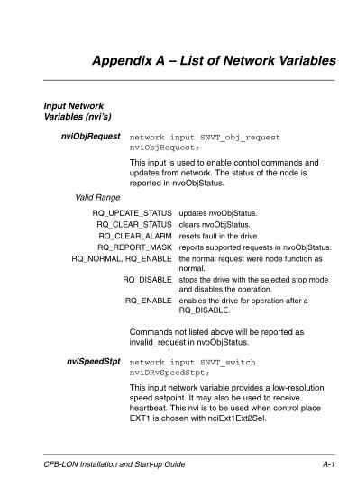
Input Network Variables (nvi’s)
nviObjRequest network input SNVT_obj_requestnviObjRequest;
This input is used to enable control commands and updates from network. The status of the node is reported in nvoObjStatus.
Valid Range
Commands not listed above will be reported as invalid_request in nvoObjStatus.
nviSpeedStpt network input SNVT_switchnviDRvSpeedStpt;
This input network variable provides a low-resolution speed setpoint. It may also be used to receive heartbeat. This nvi is to be used when control place EXT1 is chosen with nciExt1Ext2Sel.
RQ_UPDATE_STATUS updates nvoObjStatus.
RQ_CLEAR_STATUS clears nvoObjStatus.
RQ_CLEAR_ALARM resets fault in the drive.
RQ_REPORT_MASK reports supported requests in nvoObjStatus.
RQ_NORMAL, RQ_ENABLE the normal request were node function as normal.
RQ_DISABLE stops the drive with the selected stop mode and disables the operation.
RQ_ENABLE enables the drive for operation after a RQ_DISABLE.
CFB-LON Installation and Start-up Guide A-1

Appendix A – List of Network Variables
Valid Range
Defaul Value Default value is AUTO (state = 0xFF). This value will be adapted at power-up. This network variable input may use the Receive Heartbeat function depending on if Receive Heartbeat function is setup for use. The actual value of drive speed does also depend on nviDrvSpeedScale.
nviDrvSpeedScale network input SNVT_lev_percentnviDrvSpeedScale;
This input network variable provides scaling for nviDrvSpeedStpt and nviRefStpt values. For example if nviDrvSpeedStpt value is 100% and nviDrvSpeedScale value is -150%, the actual speed setpoint value is -150%, meaning 1.5 times the nominal speed in the reverse direction.
Valid Range -163.84% .. 163.83% (0.005% or 50 ppm).The value 0x7FFF represents invalid data.
Default Value Defined by nciDrvSpeedScale.
nviResetFault network input SNVT_switch nviResetFault;
This input network variable provides an input to the motor to clear the fault status in the drive.
State Value Equivalent Percent Requested Speed
0 N/A N/A STOPPED
1 0 0% 0%
1 1 to 200 0.5 to 100.0% 0.5 to 100.0%
1 201 to 255 100.0% 100.0%
0xFF N/A N/A AUTO (Invalid)
A-2 CFB-LON Installation and Start-up Guide

Appendix A – List of Network Variables
Valid Range
On a transition from 0 to 1, this input network variable clears the fault condition in the drive. Following a fault reset, this variable should be set to '0' to enable the next reset fault.
Default Value The module will power-up in a 'Enable Reset Fault' state.
nviSerialData1,nviSerialData2,nviSerialData3
network input SNVT_count nviSerialData1;network input SNVT_count nviSerialData2;network input SNVT_count nviSerialData3;
These input network variables provide inputs to Ser Link Data 1, 2 and 3.
Valid Ranges 0 .. 255
Default Values 0
Output Network Variables
nvoObjStatus network output SNVT_obj_statusnvoObjStatus;
This nvo reports node object status.
Valid Range
State Value Command
0 0% Enable Reset Fault
1 100% Reset Fault
invalid ID Invalid node ID requested
report mask Reporting supported fields
disabled If RQ_DISABLE active
electrical_fault The faulted bit in Status Word
in_alarm Alarm bit in Status Word
CFB-LON Installation and Start-up Guide A-3

Appendix A – List of Network Variables
nvoDrvCurnt network output SNVT_amp nvoDrvCurnt;
This output network variable provides the drive current in amperes.
Valid Range -3,276.8 .. 3,276.7 A (0.1 A)
nvoDrvSpeed network output SNVT_lev_percentnvoDrvSpeed;
This output network variable provides the speed of the drive as a percentage of the nominal speed. This output network variable is used as a heartbeat to monitor the health of the drive.
Valid Range -163.84% .. 163.83% (0.005% or 50 ppm). The value 0x7FFF represents invalid data.
nvoDrvStatus network output SNVT_state nvoDrvStatus;
This output network variable provides the status of the drive.
Valid Range As Status Word of the drive.
nvoRunning network output SNVT_switch nvoRunning;
This output indicates if the motor is running or not.
Valid RangeTRUE, 100% Motor is running.FALSE, 0% Motor is not running.
nvoFaulted network output SNVT_switch nvoFaulted;
This output provides information of the fault status of the drive.
Valid RangeTRUE, 100% Drive is in faulted mode.FALSE, 0% Normal mode.
A-4 CFB-LON Installation and Start-up Guide

Appendix A – List of Network Variables
nvoCtrlLoc network output SNVT_lev_disc nvoCtrlLoc;
Active control place.
Valid Range Local = 0, EXT1 = 1, EXT2 = 2
nvoDrvPwr network output SNVT_power_kilo nvoDrvPwr;
This output network variable provides the drive power in kilowatts.
Valid Range 0 .. 6,553.5 kW (0.1 kW).
nvoDrvEnrgy network output SNVT_count nvoDrvEnrgy;
This output network variable provides the energy consumed by the motor in units defined by drive manual.
nvoFreqAct network output SNVT_freq_hz nvoFreqAct;
Output frequency in Hz.
Valid Range 0 .. 6553.5 Hz (0.1 Hz).
nvoSpeedActRpm network output SNVT_count_incnvoSpeedActRpm;
Output speed in Rpm’s.
nvoTorqAct network output SNVT_count_inc nvoTorqAct;
Motor torque in units defined by drive manual.
nvoDrvTemp network output SNVT_temp_p nvoDrvTemp;
Drive power semiconductor (Power Plate) temperature in °C.
Valid Range -274 .. 6,279.5 °C (0.1 °C )
CFB-LON Installation and Start-up Guide A-5

Appendix A – List of Network Variables
nvoDrvRunHours network output SNVT_time_hournvoDrvRunHours;
Total power on time in whole hours.
Valid Range 0 .. 65535 h (1 h).
nvoPidAct1 network output SNVT_lev_percentnvoPidAct1;
PID controller feedback value 1.
Valid Range -163.84% .. 163.83% (0.005% or 50 ppm).The value 0x7FFF represents invalid data.
nvoPidAct2 network output SNVT_lev_percentnvoPidAct2;
PID controller feedback value 2.
Valid Range -163.84% .. 163.83% (0.005% or 50 ppm).The value 0x7FFF represents invalid data.
nvoDcBusVolt network output SNVT_volt nvoDcBusVolt;
DC bus voltage.
Valid Range -3,276.8 .. 3,276.7 V (0.1 V)
nvoFault1,nvoFault2,nvoFault3
network output SNVT_count nvoFault1;
network output SNVT_count nvoFault2;
network output SNVT_count nvoFault3;
These variables are the fault codes for the latest, the second latest and the third latest faults in the drive.
Valid Ranges See Table A-1 for explanation of fault codes.
nvoParValue network output SNVT_count nvoParValue;
This variable contains the data read at parameter set by nciParRead.
A-6 CFB-LON Installation and Start-up Guide

Appendix A – List of Network Variables
nvoDigInput1 tonvoDigInput5
network output SNVT_switch nvoDigInput1;tonetwork output SNVT_switch nvoDigInput5;
These variables contain the statuses of Digital Input 1 (DI1) to Digital Input 5 (DI5).
Valid Ranges
nvoDigOutput1,nvoDigOutput2
network output SNVT_switch nvoDigOutput1;
network output SNVT_switch nvoDigOutput1;
These variables contain the statuses of Digital Output 1 (relay) and Digital Output 2 (relay).
Valid Ranges See nvoDigInput1.
Configuration Network Variables
nciSndHrtBt network config input SNVT_time_secnciSndHrtBt;
This input configuration network variable provides the maximum send time in seconds for the variables nvoDrvSpeed, nvoDrvStatus and nvoSpeedActRpm.
Valid Range 0.0 .. 6553.4 s (0.1 s). The value 0xFFFF represents invalid data.
Default Value Default value = 0 (disabled).
State Value Command
0 0% Low
1 100% High
CFB-LON Installation and Start-up Guide A-7

Appendix A – List of Network Variables
nciRcvHrtBt network config input SNVT_time_secnciRcvHrtBt;
This configuration property is used to control the maximum time that elapses after the last update to input network variables nviDrvSpeedStpt or nviRefStpt. If timeout occurs, the module stops the dataset write update. The function which will be carried out by the drive depends on the user configuration (action programmable in the drive).
Valid Range 0.0 .. 6553.4 s (0.1 s). The value 0xFFFF represents invalid data.The value 0 disables the Receive Heartbeat mechanism.
Default Value Default value is 0 (disabled).
nciMinOutTm network config input SNVT_time_secnciMinOutTm;
This input configuration network variable controls the minimum period of time in seconds before the network output variables can be propagated (resent).
Valid Range 0.0 .. 6553.4 s (0.1 s).The value 0xFFFF represents invalid data.The value 0 disables transmission limiting.
Default Value Default value = 0 (disabled).
nciLocation network config input SNVT_str_ascnciLocation;
This configuration property can optionally be used to provide more descriptive physical location information than can be provided by the Neuron Chip’s 6 byte location string. The location relates to the object and not to the node.
Valid Range NULL terminated ASCII string of 31 bytes.
A-8 CFB-LON Installation and Start-up Guide

Appendix A – List of Network Variables
Default Value Default value = ASCII string containing all zeros (‘\0’).
nciNmlSpeed network config input SNVT_rpmnciNmlSpeed;
This configuration property is used to provide the nominal speed of the motor. This value is necessary to determine the minimum and maximum speed for the motor, based on the configuration properties nciMinSpeed, nciMaxSpeed (entered as percent of nominal).
Valid Range 0 .. 65,534 revolutions/minute (1 RPM). The value 0xFFFF represents invalid data.
nciNmlFreq network config input SNVT_freq_hz;
This configuration property is used to provide the nominal frequency of the motor. This value is necessary to determine the minimum and maximum frequency for the motor when in scalar control.
Valid Range 0 .. 6553.5 Hz (0.1 Hz)
nciMinSpeed network config input SNVT_lev_percentnciMinSpeed;
This configuration property is used to define the minimum speed of a motor. It’s value is entered as a percentage of nominal speed, as defined by the Nominal Speed (nciNmlSpeed) configuration value.
The value of the minimum speed must be validated against the value of the maximum speed as follows:
-163.0% � minimum speed � maximum speed � 163.0%
Valid Range -163.84% .. 163.83% (0.005% or 50 ppm).The value 0x7FFF represents invalid data.
CFB-LON Installation and Start-up Guide A-9

Appendix A – List of Network Variables
nciMaxSpeed network config input SNVT_lev_percentnciMaxSpeed;
This configuration property is used to define the maximum speed of a motor. It’s value is entered as a percent of nominal speed, as defined by the Nominal Speed (nciNomSpeed) configuration value.
The value of the maximum speed must be validated against the value of the minimum speed as follows:
-163.0% � minimum speed � maximum speed � 163.0%
Valid Range -163.84% .. 163.83% (0.005% or 50 ppm).The value 0x7FFF represents invalid data.
nciRampUpTm network config input SNVT_time_secnciRampUpTm;
This configuration property is used to provide to set the ramp up time of the drive in seconds.
Valid Range 0.0 .. 6553.4 s (0.1 s). The value 0xFFFF represents invalid data.
nciRampDownTm network config input SNVT_time_secnciRampUpTm;
This configuration property is used to provide to set the ramp down time of the drive in seconds.
Valid Range 0.0 .. 6553.4 s (0.1 s). The value 0xFFFF represents invalid data.
nciCurrLimit network config input SNVT_ampnciCurrLimit;
This input configuration network variable limits the drive maximum output current.
Valid Range -3,276.8 .. 3,276.7 A (0.1 A)
A-10 CFB-LON Installation and Start-up Guide

Appendix A – List of Network Variables
nciPidGain network config input SNVT_lev_percentnciPidGain;
PID controller gain in percents.
Valid Range -163.84% .. 163.83% (0.005% or 50 ppm).The value 0x7FFF represents invalid data.
nciPidTime network config input SNVT_time_secnciPidTime;
PID controller integration time in seconds.
Valid Range 0.0 .. 6553.4 s (0.1 s). The value 0xFFFF represents invalid data.
nciPidDerTime network config input SNVT_time_secnciPidDerTime;
PID controller derivation time in seconds.
Valid Range 0.0 .. 6553.4 s (0.1 s). The value 0xFFFF represents invalid data.
nciPidMacroSel network config input SNVT_switchnciPidMacroSel;
Selects which PID controller (1 or 2) nciPidGain, nciPidTime and nciPidDerTime should control.
Valid Range
State Value Command
0 0% PID 1 Selected
1 100% PID 2 Selected
CFB-LON Installation and Start-up Guide A-11

Appendix A – List of Network Variables
nciDrvSpeedScale network config input SNVT_lev_percentnciDrvSpeedScale;
Default value for nviDrvSpeedScale.
Valid Range -163.84% .. 163.83% (0.005% or 50 ppm).The value 0x7FFF represents invalid data.
Default Value 0
nciStopMode network config input SNVT_switchnciStopMode;
This input network variable is used to choose between coast and ramp stop.
Valid Range OFF = COAST, ON = RAMP
Default Value COAST
nciStopLevel network config input SNVT_lev_percentnciStopLevel;
Stop level value in ramp stop mode. Value relative to nvoDrvSpeed i.e. value 5% corresponds to nvoDrvSpeed value 5% and 50% to 50%.
Valid Range Valid range 5% .. 100%-163.84% .. 163.83% (0.005% or 50 ppm).The value 0x7FFF represents invalid data.
Default Value Default value 5%.
nciExt1Ext2Sel network config input SNVT_switchnciExt1Ext2Sel;
Select between nviDrvSpeedStpt and internal speed control in the drive. The parameter 11.02 must be set to COMM to enable ext1/ext2 selection from the LonWorks network.
Valid Range OFF = EXT1, ON = EXT2
A-12 CFB-LON Installation and Start-up Guide

Appendix A – List of Network Variables
Default Value The default value is read from the drive. Otherwise EXT1
nciParValue network config input SNVT_count_incnciParValue;
This nci is used as a value input for the user selected parameter nciParWrite. The scaling is defined by integer scalings described in the User’s Manual.
nciParRead network config input SNVT_countnciParRead;
Chooses the parameter value to be read from the drive.
nciParWrite network config input SNVT_countnciParWrite;
Chooses the parameter value to be written to the drive.
Fault CodesTable A-1 Fault Codes
Fault Code
TypeFault Code Parameter
0 No Fault 0x0000
1 Overcurrent 0x2300
2 DC Overvoltage 0x3210
3 ACS160 Overtemp 0x4310
4 Short Circuit 0x2340
5 Output Overload 0x2310
6 DC Undervoltage 0x3120
7 Analogue Input 1 0x7081
8 Analogue Input 2 0x7082
9 Motor Overtemp 0x4210
CFB-LON Installation and Start-up Guide A-13

Appendix A – List of Network Variables
10 Panel Loss 0x5300
11 Parametering 0x6320
12 Motor Stall 0x7120
13 Serial Comm. Loss 0x7510
14 External Fault Signal
0x9000
15 Output Earth Fault 0x2120
16 DC Bus Ripple 0x3100
17 Underload 0x7120
18 Reserved 0x0000
19 Reserved 0x0000
20 AI Out of Range 0x1000
21-29 Hardware Error 0x5081-0x5089
30 BR Res Overload 0x7110
A-14 CFB-LON Installation and Start-up Guide

D(lo
DuMcoPcuI(
Appendix B – Technical Data
LONWORKS® Network
CFB-LON compatible devices: All devices equipped with FTT-10A compatible transceivers
Size of the network segment: Max. 64 nodes
Medium: Special LON® cable
• Termination: Built in the CFB-LON Module
• Cable specifications: See the following tables
Table B-1 LONWORKS® network cable specifications.
Control / signalling-
grade 16 AWG (1.3 mm)
General purpose-
grade 16 AWG(1.3 mm)
Data-grade level 4
22 AWG(0.65 mm)
JY (St) Y 2×2×0.8
20.4 AWG(0.8 mm)
C resistance at 20 °C) op maximum
28.2 �/km 28.2 �/km 118 �/km 74.0 �/km
C resistance nbalance (max.)
5%
utual apacitance f a pair (max.)
58 nF/km 74 nF/km 56 nF/km 100 nF/km
air-to-ground apacitance nbalance (max.)
3.28 nF/km
mpedance nominal)
95 � at 1.0 MHz
100 ��at 1.0 MHz
102 � �15% at 772 kHz100 � �15% at 1, 4, 8, 10, 16 and 20 MHz
CFB-LON Installation and Start-up Guide B-1

Appendix B – Technical Data
A2
PmCp
ttenuation (at 0 °C) (max.)
15 dB/km at 772 kHz18 dB/km at 1.0 MHz36 dB/km at 4.0 MHz49 dB/km at 8.0 MHz56 dB/km at 10.0 MHz72 dB/km at 16.0 MHz79 dB/km at 20.0 MHz
air twists per etre
20 (nominal) 20 (minimum) 5 (minimum)
able arameters
- single twisted pair
- stranded 19/29
- unshielded- Tefzel Insulation & Jacket High Temperature 150 °C max.
- single twisted pair
- stranded 19/29
- unshielded- PVC Insulation & Jacket Medium Temperature 80 °C max.
- twisted pair, single or multiple
- typically solid and unshielded
- wire pair:red/black
- per DIN VDE0815
- 4-wire helicaltwist
- solid - shielded
Control / signalling-
grade 16 AWG (1.3 mm)
General purpose-
grade 16 AWG(1.3 mm)
Data-grade level 4
22 AWG(0.65 mm)
JY (St) Y 2×2×0.8
20.4 AWG(0.8 mm)
B-2 CFB-LON Installation and Start-up Guide

Appendix B – Technical Data
Table B-2 LONWORKS® network, maximum bus lengths.
Topology: Supports free topology wiring, and will accommodate bus, star, loop, or any combination of these topologies
Serial communication type: Asynchronous, half Duplex
Transfer rate: 78 kbit/s
Protocol: LonTalk®
Documents: LONMARK® Layers 1-6 Interoperability Guidelines, version 3.0
Control / signalling-
grade 16 AWG(1.3 mm)
General purpose-
grade 16 AWG (1.3 mm)
Data-grade level 4
22 AWG(0.65 mm)
JY (St) Y 2×2×0.8
20.4 AWG(0.8 mm)
Doubly-terminated bus topology
Bus length 2200 m 2200 m 1150 m 750 m
Stub length 3 m 3 m 3 m 3 m
Singly-terminated free topology
Node-to-node distance
500 m 400 m 400 m 320 m
Total wire length
500 m 500 m 500 m 500 m
CFB-LON Installation and Start-up Guide B-3

Appendix B – Technical Data
CFB-LON Enclosure: Cast aluminium, dimensions 124 × 79 × 42 mm (without cable glands)
Degree of Protection: IP65
Mounting: Onto ACS 160 drive
Settings: Via drive interface (control panel)
Connectors:
� One Phoenix Contact MC1,5/5-ST-3,81 (5-pole, cross-section 1.5 mm2 max.) screw terminal block for fieldbus connection:
General:
• Complies with EMC Standards EN 50081-1 and EN 50082-2
Terminal Description
1 SHIELD Cable screen
2 GND Ground
3 Service Pin For connecting an external Service Pin pushbutton
4 Net BNetwork cable connection
5 Net A
B-4 CFB-LON Installation and Start-up Guide

Appendix C – Ambient Conditions
Operation The following conditions apply to stationary use of the module.
Installation Site Altitude: 0 to 2000 m above sea level. If the installation site is higher than 2000 m above sea level, please contact your local ABB representative for further information.
Temperature: -10 to +50 °C
Contamination Levels (IEC 721-3-3):Chemical gases: Class 3C3Solid particles: Class 3S3
Sinusoidal Vibration(IEC 721-3-3, 2nd Edition 1994-12):Max 3 mm (2 to 9 Hz)Max 10 m/s2 (9 to 200 Hz)
Shock (IEC 721-3-3, 2nd Edition 1994-12):Max 250 m/s2, 6 ms
Storage and Transportation
The following conditions apply to storage and transportation of the module in the protective package.
Temperature: -40 to +70 °C
Contamination Levels (IEC 721-3-3):Storage: Chemical gases: Class 1C2
Solid particles: Class 1S3
Transportation: Chemical gases: Class 2C2Solid particles: Class 2S2
Shock (IEC 721-3-3, 2nd Edition 1994-12):Max 300 m/s2, 18 ms
CFB-LON Installation and Start-up Guide C-1

Appendix C – Ambient Conditions
C-2 CFB-LON Installation and Start-up Guide


ABB Industry OyDrivesP.O. Box 184FIN-00381 HelsinkiFINLANDTelephone:+358 10 222 000
CF
B-L
ON
/EN
3BF
E 6
4421
158
R01
25E
FF
EC
TIV
E: 1
.9.2
001
ABB Automation Inc.Drives & Power Products16250 West Glendale DriveNew Berlin, WI 53151USATelephone:262 785-8378
Fax: +358 10 222 2681Internet: www.abb.com
800 243-4384Fax: 262 780-5135