Embed Size (px)
Citation preview
1
Fabrication
#4 DrillingThis brief gives advice for:
l Equipment
l Procedures
l Trouble Shooting
l Equipment Suppliers
l Additional Technical Informationand Assistance
TECHBRIEF
Equipment
DrillsAny commercially available, power-driven equipment isacceptable. This includes portable drills, drill presses,lathes, automatic multiple-spindle drilling units, CNCrouters and machining centers.
Drill BitsSeveral manufacturers offer drill bits designed especiallyfor plastics. Drill bits are commonly made of high-speedsteel (HSS), cobalt, HSS with carbide tips or solidcarbide. Metal-working high-speed steel twist drill bitscan be used with some modification.
Standard metal-working drill bits are designed toaggressively cut into metal as they are fed into it. Ifused on acrylic without modification, these bits will chipand cause other damage to the plastic. These drill bitsmust be reground in order to scrape the plastic insteadof sharply cutting into the material and gouging it. Thereare three points to consider when modifying a standardmetal-working twist drill for plastics.
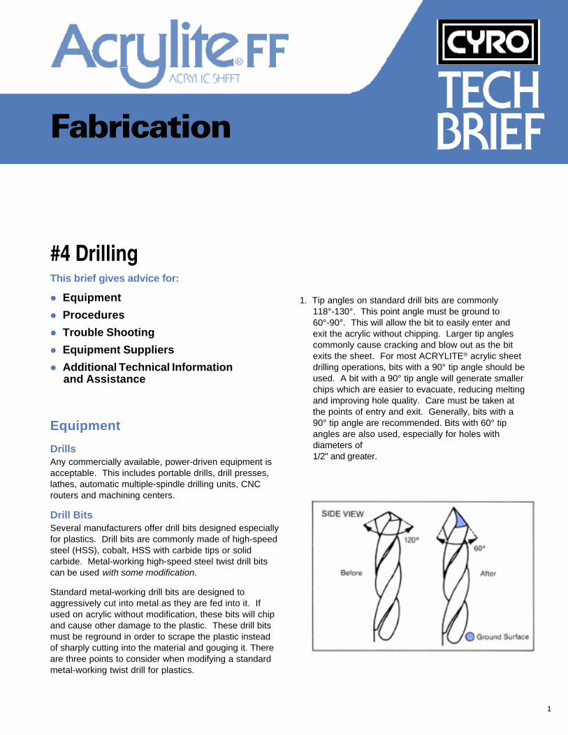
1. Tip angles on standard drill bits are commonly118°-130°. This point angle must be ground to60°-90°. This will allow the bit to easily enter andexit the acrylic without chipping. Larger tip anglescommonly cause cracking and blow out as the bitexits the sheet. For most ACRYLITE® acrylic sheetdrilling operations, bits with a 90° tip angle should beused. A bit with a 90° tip angle will generate smallerchips which are easier to evacuate, reducing meltingand improving hole quality. Care must be taken atthe points of entry and exit. Generally, bits with a90° tip angle are recommended. Bits with 60° tipangles are also used, especially for holes withdiameters of1/2" and greater.
2
Bit geometry affects the quality of drilled holes since itaffects chip size and chip evacuation. Larger diameterbits and bits with smaller tip angles produce larger chips.If hole depth (H) is less than bit diameter (D), large chipsare easily ejected. As the depth of the hole increases,i.e. H>D, larger chips become more difficult to ejectbecause of the close clearance between the bit and thehole walls. Increasing bit tip angle decreases the size ofgenerated chips, facilitating chip ejection. However, asmentioned above, if the tip angle is too large, larger than90°, blow out and chipping may be a problem when thebit exits the acrylic.
Procedures
Be sure to follow the manufacturers’ safety recommen-dations for equipment and materials used withACRYLITE FF® acrylic sheet.
When drilling ACRYLITE sheet, heat is generated due tothe close clearance between the bit and the hole wallsand because of the difficulty of chip ejection. As men-tioned above, chip ejection becomes more difficult asthe hole gets deeper. Friction between the bit and thematerial also increases because of acrylic’s relativelylow thermal conductivity and high thermal expansioncoefficient, which cause the material to expand. Thesefactors, if not accounted for, can cause the material tomelt and gum, giving less than optimum hole quality. Itis therefore essential to reduce generated heat and toremove chips quickly.
The work piece should be held firmly or, preferably,solidly clamped to the worktable. It is best to backupthe piece being drilled with acrylic, other thermoplasticsheet or medium density fiberboard (MDF) so the drill bitwill continue on into solid material as it penetrates thebottom surface. This will prevent chipping of the bottomsurface. Use a slow feed rate when starting the drillingaction to allow the bit to enter the material, and alsoslow the feed rate as the bit exits the bottom surface toprevent chipping.
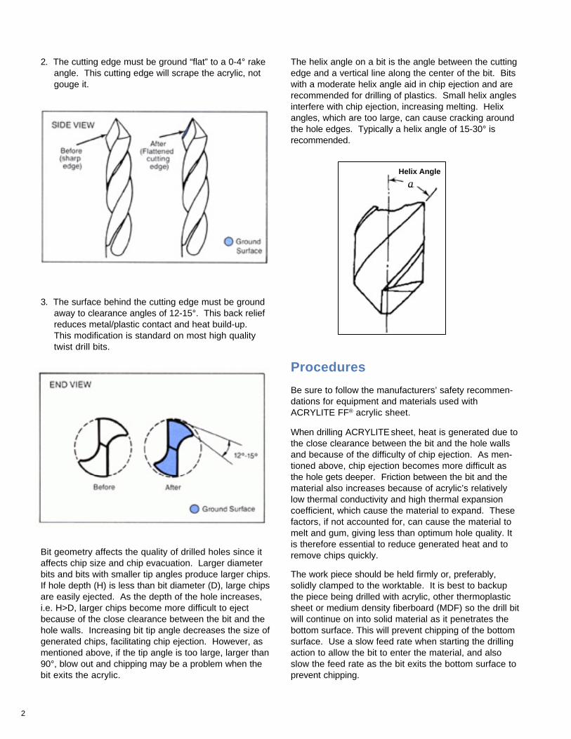
3. The surface behind the cutting edge must be groundaway to clearance angles of 12-15°. This back reliefreduces metal/plastic contact and heat build-up.This modification is standard on most high qualitytwist drill bits.
aHelix Angle
2. The cutting edge must be ground “flat” to a 0-4° rakeangle. This cutting edge will scrape the acrylic, notgouge it.
The helix angle on a bit is the angle between the cuttingedge and a vertical line along the center of the bit. Bitswith a moderate helix angle aid in chip ejection and arerecommended for drilling of plastics. Small helix anglesinterfere with chip ejection, increasing melting. Helixangles, which are too large, can cause cracking aroundthe hole edges. Typically a helix angle of 15-30° isrecommended.
3
Table 1: Recommended values for SFM and IPR
Diameter of bit (in.) SFM IPR1/16 20-160 0.0011/8 20-160 0.0021/4 20-160 0.0043/8 20-160 0.0061/2 30-90 0.0083/4 30-90 0.010≥1 30-90 0.012-0.015
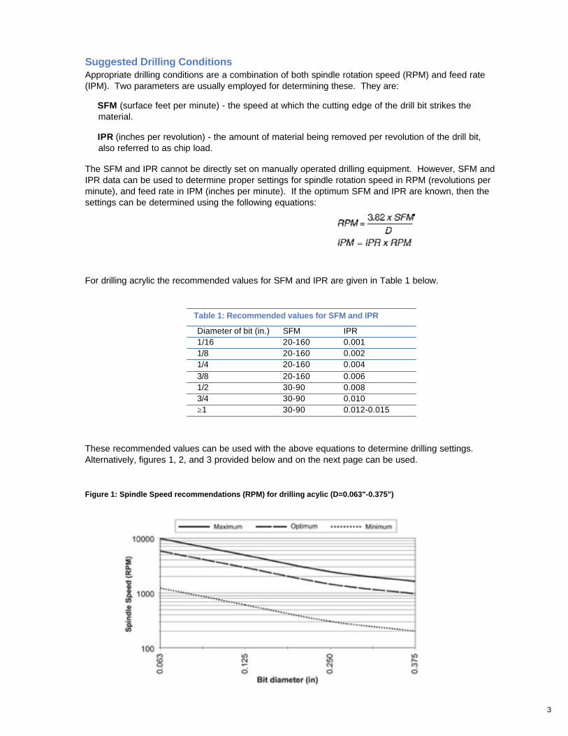
These recommended values can be used with the above equations to determine drilling settings.Alternatively, figures 1, 2, and 3 provided below and on the next page can be used.
For drilling acrylic the recommended values for SFM and IPR are given in Table 1 below.
Figure 1: Spindle Speed recommendations (RPM) for drilling acylic (D=0.063"-0.375")
Suggested Drilling ConditionsAppropriate drilling conditions are a combination of both spindle rotation speed (RPM) and feed rate(IPM). Two parameters are usually employed for determining these. They are:
SFM (surface feet per minute) - the speed at which the cutting edge of the drill bit strikes thematerial.
IPR (inches per revolution) - the amount of material being removed per revolution of the drill bit,also referred to as chip load.
The SFM and IPR cannot be directly set on manually operated drilling equipment. However, SFM andIPR data can be used to determine proper settings for spindle rotation speed in RPM (revolutions perminute), and feed rate in IPM (inches per minute). If the optimum SFM and IPR are known, then thesettings can be determined using the following equations:
4
As indicated in the graphs and table above, lower SFM’sare required for larger drill bits. This is to ensuresmooth, vibration-free drilling because large bits will tendto grab the material more. As a result, feed rate mustgenerally be slowed down in order to prevent chippingand consequently spindle speed must be reduced toprevent melting.
For H>D, peck drilling, drilling in increments and remov-ing the bit from the material periodically to clear chips,should be employed.
Manual DrillingManual drilling operations should be performed at slowerspeeds and feed rates than automated or CNC drilling,taking into account the diameter of the bit, materialthickness, and ability to cool during drilling. Additionally,peck drilling should be employed in deeper holes toreduce melting.
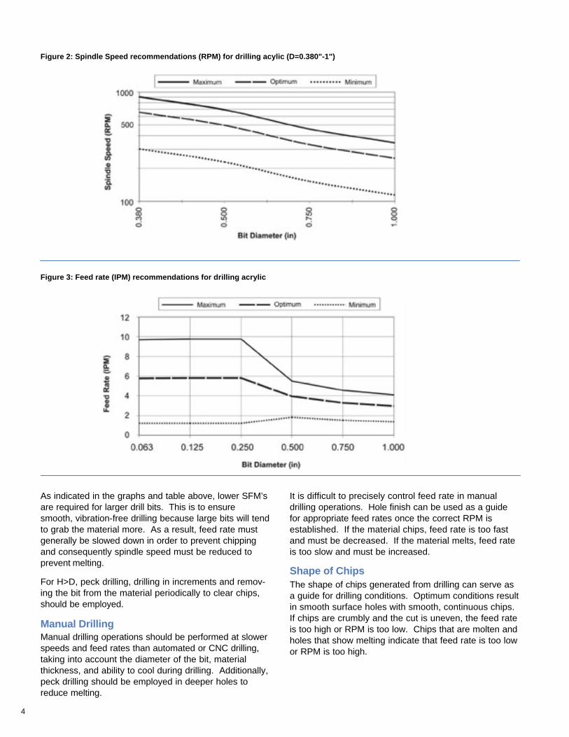
It is difficult to precisely control feed rate in manualdrilling operations. Hole finish can be used as a guidefor appropriate feed rates once the correct RPM isestablished. If the material chips, feed rate is too fastand must be decreased. If the material melts, feed rateis too slow and must be increased.
Shape of ChipsThe shape of chips generated from drilling can serve asa guide for drilling conditions. Optimum conditions resultin smooth surface holes with smooth, continuous chips.If chips are crumbly and the cut is uneven, the feed rateis too high or RPM is too low. Chips that are molten andholes that show melting indicate that feed rate is too lowor RPM is too high.
Figure 2: Spindle Speed recommendations (RPM) for drilling acylic (D=0.380"-1")
Figure 3: Feed rate (IPM) recommendations for drilling acrylic
5
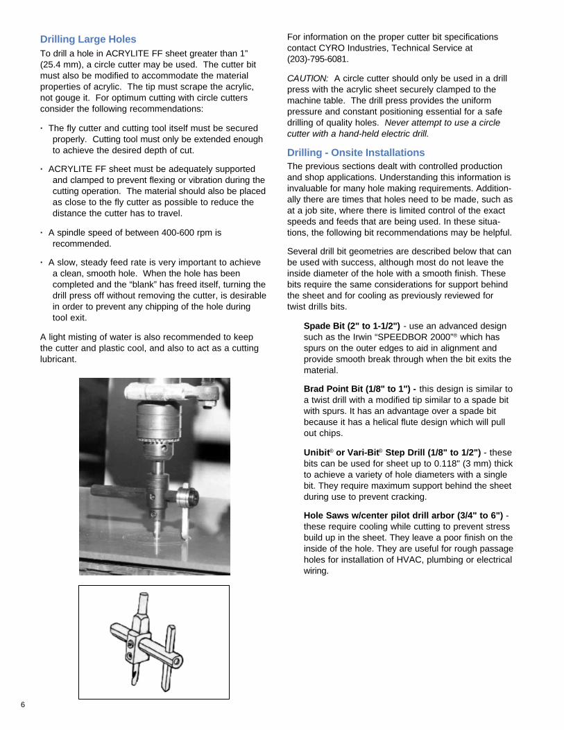
Circuit Board DrillingCircuit board drilling is a specialcase where automated machinesdrill thousands of tiny holes at veryhigh speed. Specially designed bitsare required. Feed rate and RPMrecommendations are provided infigures 4 and 5.
Figure 4: Spindle speed (RPM) recommendations for acrylic circuit board drilling
Figure 5: Feed rate (IPM) recommendations for acrylic circuit board drilling
CoolantsAir or liquid coolants should be used whenever possible.Coolants reduce generated heat, and therefore improvehole quality. In certain hole depths and sizes, coolantsare necessary to prevent melting. As a general rule,coolants should be used when the depth of the hole (H)exceeds bit diameter (D) (e.g. for D=0.250", a coolantshould be used for H>0.250"). Coolants should also beused for holes greater than or equal to 1/2" in diameter(D≥ 1/2").
Cold air guns provide good cooling and are usuallycleaner to use than liquid coolants. However, liquidcoolants provide more cooling, as the liquid can trickledown the hole as the bit goes through the material,resulting in better hole finishes. Water, kerosene,mineral oils and other compatible solvents can beused.
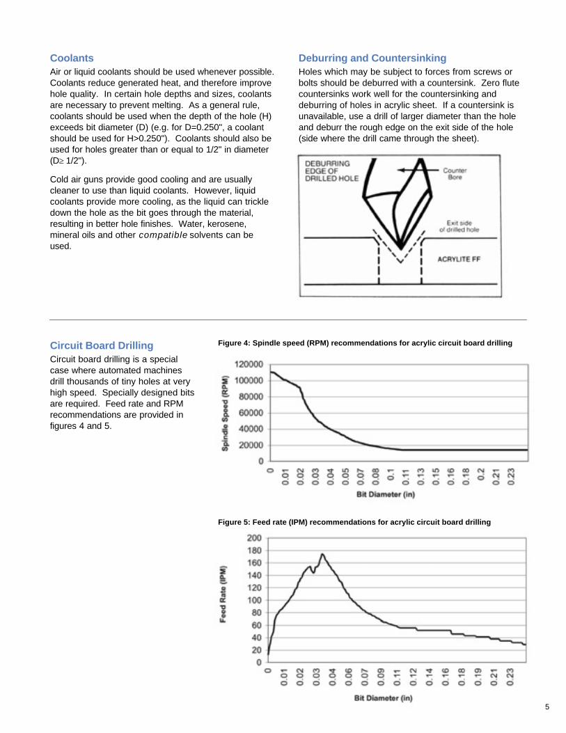
Deburring and CountersinkingHoles which may be subject to forces from screws orbolts should be deburred with a countersink. Zero flutecountersinks work well for the countersinking anddeburring of holes in acrylic sheet. If a countersink isunavailable, use a drill of larger diameter than the holeand deburr the rough edge on the exit side of the hole(side where the drill came through the sheet).
6
Drilling Large HolesTo drill a hole in ACRYLITE FF sheet greater than 1”(25.4 mm), a circle cutter may be used. The cutter bitmust also be modified to accommodate the materialproperties of acrylic. The tip must scrape the acrylic,not gouge it. For optimum cutting with circle cuttersconsider the following recommendations:
· The fly cutter and cutting tool itself must be securedproperly. Cutting tool must only be extended enoughto achieve the desired depth of cut.
· ACRYLITE FF sheet must be adequately supportedand clamped to prevent flexing or vibration during thecutting operation. The material should also be placedas close to the fly cutter as possible to reduce thedistance the cutter has to travel.
· A spindle speed of between 400-600 rpm isrecommended.
· A slow, steady feed rate is very important to achievea clean, smooth hole. When the hole has beencompleted and the “blank” has freed itself, turning thedrill press off without removing the cutter, is desirablein order to prevent any chipping of the hole duringtool exit.
A light misting of water is also recommended to keepthe cutter and plastic cool, and also to act as a cuttinglubricant.
For information on the proper cutter bit specificationscontact CYRO Industries, Technical Service at(203)-795-6081.
CAUTION: A circle cutter should only be used in a drillpress with the acrylic sheet securely clamped to themachine table. The drill press provides the uniformpressure and constant positioning essential for a safedrilling of quality holes. Never attempt to use a circlecutter with a hand-held electric drill.
Drilling - Onsite InstallationsThe previous sections dealt with controlled productionand shop applications. Understanding this information isinvaluable for many hole making requirements. Addition-ally there are times that holes need to be made, such asat a job site, where there is limited control of the exactspeeds and feeds that are being used. In these situa-tions, the following bit recommendations may be helpful.
Several drill bit geometries are described below that canbe used with success, although most do not leave theinside diameter of the hole with a smooth finish. Thesebits require the same considerations for support behindthe sheet and for cooling as previously reviewed fortwist drills bits.
Spade Bit (2" to 1-1/2") - use an advanced designsuch as the Irwin “SPEEDBOR 2000”® which hasspurs on the outer edges to aid in alignment andprovide smooth break through when the bit exits thematerial.
Brad Point Bit (1/8" to 1") - this design is similar toa twist drill with a modified tip similar to a spade bitwith spurs. It has an advantage over a spade bitbecause it has a helical flute design which will pullout chips.
Unibit® or Vari-Bit® Step Drill (1/8" to 1/2") - thesebits can be used for sheet up to 0.118" (3 mm) thickto achieve a variety of hole diameters with a singlebit. They require maximum support behind the sheetduring use to prevent cracking.
Hole Saws w/center pilot drill arbor (3/4" to 6") -these require cooling while cutting to prevent stressbuild up in the sheet. They leave a poor finish on theinside of the hole. They are useful for rough passageholes for installation of HVAC, plumbing or electricalwiring.
7
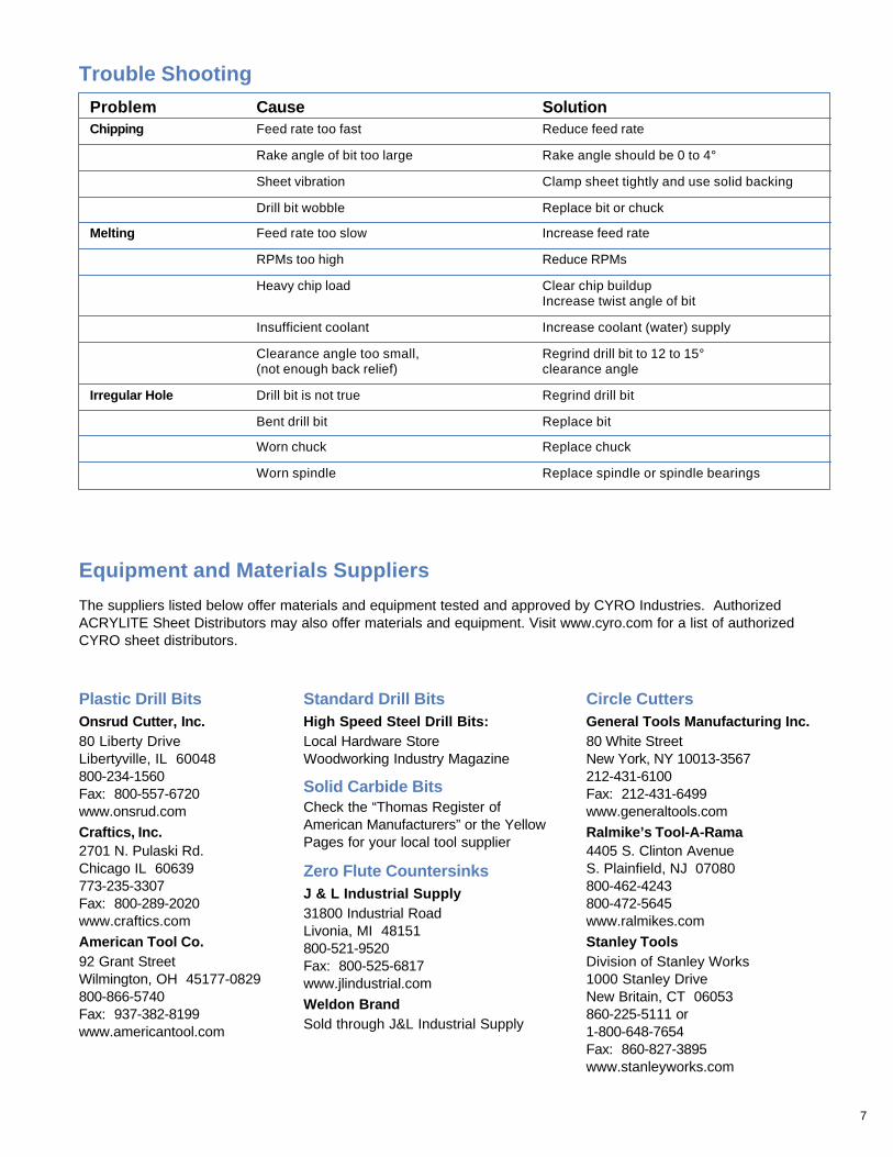
Trouble Shooting
Problem Cause SolutionChipping Feed rate too fast Reduce feed rate
Rake angle of bit too large Rake angle should be 0 to 4°
Sheet vibration Clamp sheet tightly and use solid backing
Drill bit wobble Replace bit or chuck
Melting Feed rate too slow Increase feed rate
RPMs too high Reduce RPMs
Heavy chip load Clear chip buildupIncrease twist angle of bit
Insufficient coolant Increase coolant (water) supply
Clearance angle too small, Regrind drill bit to 12 to 15°(not enough back relief) clearance angle
Irregular Hole Drill bit is not true Regrind drill bit
Bent drill bit Replace bit
Worn chuck Replace chuck
Worn spindle Replace spindle or spindle bearings
Equipment and Materials Suppliers
The suppliers listed below offer materials and equipment tested and approved by CYRO Industries. AuthorizedACRYLITE Sheet Distributors may also offer materials and equipment. Visit www.cyro.com for a list of authorizedCYRO sheet distributors.
Circle CuttersGeneral Tools Manufacturing Inc.80 White StreetNew York, NY 10013-3567212-431-6100Fax: 212-431-6499www.generaltools.com
Ralmike’s Tool-A-Rama4405 S. Clinton AvenueS. Plainfield, NJ 07080800-462-4243800-472-5645www.ralmikes.com
Stanley ToolsDivision of Stanley Works1000 Stanley DriveNew Britain, CT 06053860-225-5111 or1-800-648-7654Fax: 860-827-3895www.stanleyworks.com
Standard Drill BitsHigh Speed Steel Drill Bits:Local Hardware StoreWoodworking Industry Magazine
Solid Carbide BitsCheck the “Thomas Register ofAmerican Manufacturers” or the YellowPages for your local tool supplier
Zero Flute CountersinksJ & L Industrial Supply31800 Industrial RoadLivonia, MI 48151800-521-9520Fax: 800-525-6817www.jlindustrial.com
Weldon BrandSold through J&L Industrial Supply
Plastic Drill BitsOnsrud Cutter, Inc.80 Liberty DriveLibertyville, IL 60048800-234-1560Fax: 800-557-6720www.onsrud.com
Craftics, Inc.2701 N. Pulaski Rd.Chicago IL 60639773-235-3307Fax: 800-289-2020www.craftics.com
American Tool Co.92 Grant StreetWilmington, OH 45177-0829800-866-5740Fax: 937-382-8199www.americantool.com
8 1319(4E)-1001-5RA © 2001 CYRO Industries. All Rights Reserved. Printed in USA.
Additional Technical Informationand AssistanceWe invite you to visit our TechKnowlogy Centeron www.cyro.com.
Visitors have immediate access to frequently askedquestions, technical concerns, physical properties,processing conditions, fabrication tips, regulatorycompliance information, engineering guidelines, tipsfor troubleshooting, and hundreds of other facts aboutacrylics from one of North America’s leadingmanufacturers of acrylic-basedpolymer and sheet products.
Fire PrecautionsACRYLITE FF sheet is a combustible thermoplastic. Precautions should betaken to protect this material from flames and high heat sources. ACRYLITE FFsheet usually burns rapidly to completion if not extinguished. The products ofcombustion, if sufficient air is present, are carbon dioxide and water. However,in many fires sufficient air will not be available and toxic carbon monoxide willbe formed, as it will when other common combustible materials are burned. Weurge good judgement in the use of this versatile material and recommend thatbuilding codes be followed carefully to assure it is used properly.CompatibilityLike other plastic materials, ACRYLITE FF sheet is subject to crazing, crackingor discoloration if brought into contact with incompatible materials. Thesematerials may include cleaners, polishes, adhesives, sealants, gasketing orpackaging materials, cutting emulsions, etc. See the Tech Briefs in this seriesfor more information, or contact your ACRYLITE Sheet Distributor or the CYROTechnical Center for information on a specific product.
Important Notice:The information and statements herein are believed to be reliable but are not tobe construed as a warranty or representation for which we assume legalresponsibility. Users should undertake sufficient verification and testing todetermine the suitability for their own particular purpose of any information orproducts referred to herein. NO WARRANTY OF FITNESS FOR PARTICULARPURPOSE IS MADE. Nothing herein is to be taken as permission, inducementor recommendation to practice any patented invention without a license.
Sales OfficesFor the name of your local Authorized Distributor,call 800-631-5384, visit www.cyro.com, or contactthe nearest regional sales office:
Eastern Region100 Enterpise DrivePO Box 5055Rockaway, NJ 07866973-442-6130
South/Central Region101 East Park Blvd.Suite 1039Plano, TX 75074972-424-6830
Western Region3180 Crow Canyon PlaceSuite 240San Ramon, CA 94583925-866-9300
CYRO Canada Inc.6285 Northam DriveSuite 100Mississauga,Ontario L4V 1X5905-677-1388800-268-4743
Technical ServiceFor more information or specific questions aboutyour project, contact CYRO’s Technical ServiceRepresentatives.
CYRO Industries25 Executive Blvd.Orange, CT 06477203-795-6081
CYRO Canada Inc.6285 Northam DriveSuite 100Mississauga,Ontario L4V 1X5905-677-1388800-268-4743
Web site: www.cyro.com