Embed Size (px)
Citation preview
VV
O Series 100°C acuum Drying Oven
USER’S MANUAL
200 Connell Drive Ste 1900, Berkeley Heights, NJ 07922 USA
Tel: 888-988-0899 Fax: 888-988-1899 E-mail: [email protected]
Web site: www.AcrossInternational.com
VO SERIES 100°C VACUUM DRYING OVEN USER’S MANUAL
- 1 -
Index Attention …………………………………………………………………………………….……2
1. Oven components and vacuum pump connections..…………………………………………3
2. Features and specifications………...……………………………………………….…………5
3. Guideline for using the vacuum oven…………………………………………………………5
4. Operation…...………………………………………..…………………………………………6
5. How to calibrate your vacuum oven.………………………………………..…………..……9
6. Troubleshooting …………………………………………………………………...…………10
7. Schematic diagram and temperature controller connections …………………………..…11
VO SERIES 100°C VACUUM DRYING OVEN USER’S MANUAL
Attention Thank you for purchasing our VO series vacuum drying oven, please read this manual carefully before operating the unit. Across International is not responsible for any injury or damage caused by misuse. Caution
Avoid vibration or any corrosive/erosive gas around the oven.
Working environment: 5-40°C, relative humidity: less than 85%
If sample releases vapor under heating, place a dryer between the vacuum pump and the oven to
avoid vapor damage to the pump.
Always wear thermal gloves and protective goggles during operation.
Always use the power cord that comes with the unit, never modify the cable.
Keep oven away from any electromagnetic interference and do not unplug the oven during normal
operation.
Do not try to heat flammable/explosive materials or materials that may release corrosive substances.
IF YOU MAUST HEAT FLAMABLE MATERIALS, it is very important that before removal from
the oven, allow adequate time for the oven temperature to fall below the ignition point. This extra
measure will help avoid a fire caused by the oxygenation reaction.
When vacuuming is done, the vacuum valve should be closed first before turning off the power to
the vacuum pump; otherwise vacuum pump oil may backflow into the oven.
Keep the oven clean at all time; clean the glass and chamber with soft cotton cloth after each use.
If oven is to be kept idle for a long time, protect its circuit board with neutral grease or Vaseline to
avoid corrosion, and cover the oven entirely to keep it away from dust and moisture.
Oven must be unplugged under the following circumstances
Repairing
Moving the oven
Not used for a long time
- 2 -
VO SERIES 100°C VACUUM DRYING OVEN USER’S MANUAL
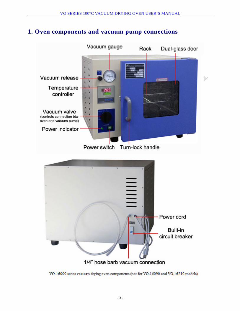
1. Oven components and vacuum pump connections
- 3 -
VO SERIES 100°C VACUUM DRYING OVEN USER’S MANUAL
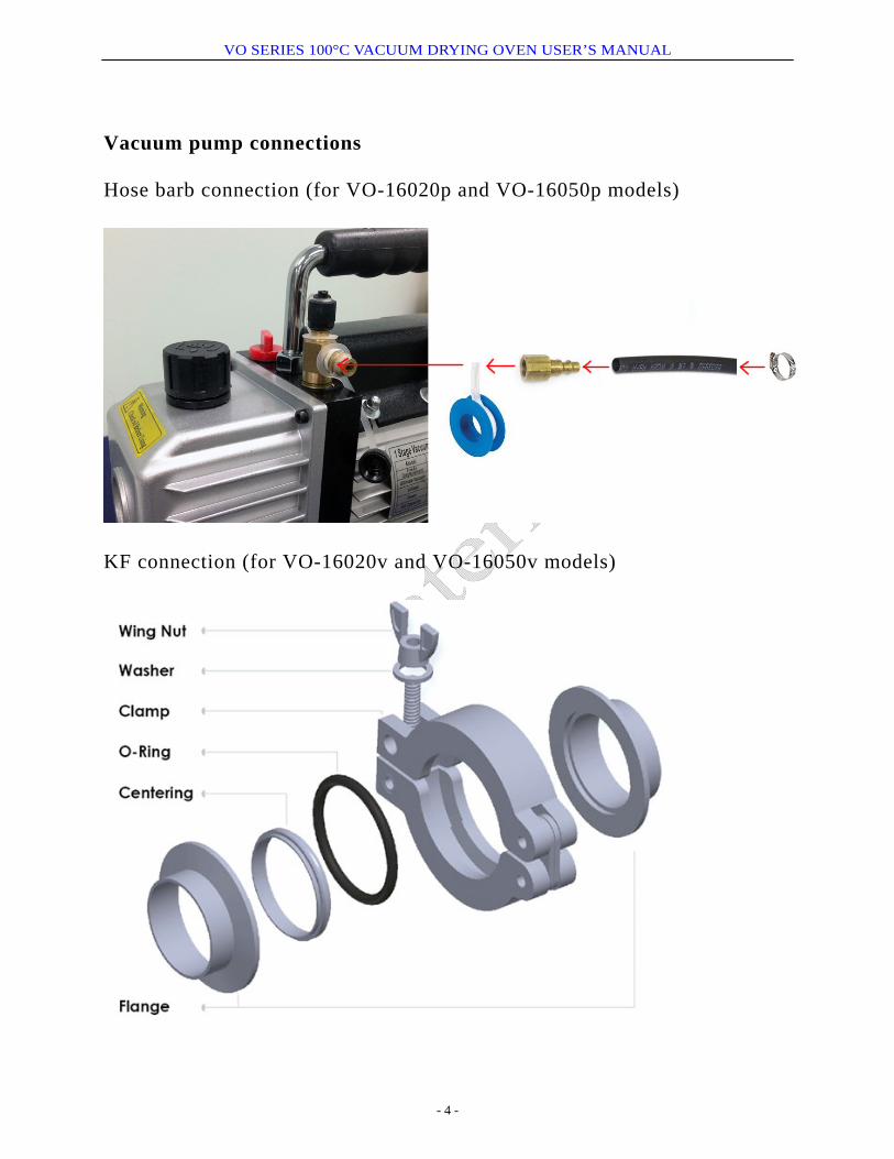
Vacuum pump connections Hose barb connection (for VO-16020p and VO-16050p models)
KF connection (for VO-16020v and VO-16050v models)
- 4 -
VO SERIES 100°C VACUUM DRYING OVEN USER’S MANUAL
- 5 -
2. Features and specifications
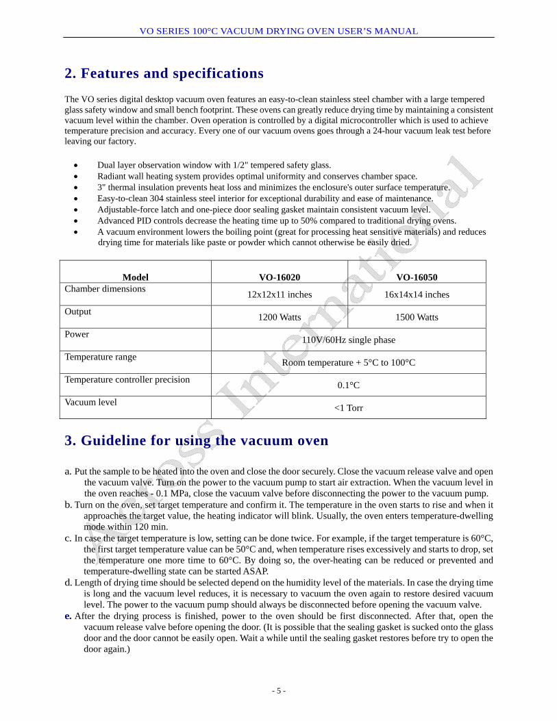
The VO series digital desktop vacuum oven features an easy-to-clean stainless steel chamber with a large tempered glass safety window and small bench footprint. These ovens can greatly reduce drying time by maintaining a consistent vacuum level within the chamber. Oven operation is controlled by a digital microcontroller which is used to achieve temperature precision and accuracy. Every one of our vacuum ovens goes through a 24-hour vacuum leak test before leaving our factory.
• Dual layer observation window with 1/2" tempered safety glass. • Radiant wall heating system provides optimal uniformity and conserves chamber space. • 3" thermal insulation prevents heat loss and minimizes the enclosure's outer surface temperature. • Easy-to-clean 304 stainless steel interior for exceptional durability and ease of maintenance. • Adjustable-force latch and one-piece door sealing gasket maintain consistent vacuum level. • Advanced PID controls decrease the heating time up to 50% compared to traditional drying ovens. • A vacuum environment lowers the boiling point (great for processing heat sensitive materials) and reduces
drying time for materials like paste or powder which cannot otherwise be easily dried.
Model
VO-16020
VO-16050
Chamber dimensions 12x12x11 inches 16x14x14 inches
Output 1200 Watts 1500 Watts
Power 110V/60Hz single phase
Temperature range Room temperature + 5°C to 100°C
Temperature controller precision 0.1°C
Vacuum level <1 Torr
3. Guideline for using the vacuum oven a. Put the sample to be heated into the oven and close the door securely. Close the vacuum release valve and open
the vacuum valve. Turn on the power to the vacuum pump to start air extraction. When the vacuum level in the oven reaches - 0.1 MPa, close the vacuum valve before disconnecting the power to the vacuum pump.
b. Turn on the oven, set target temperature and confirm it. The temperature in the oven starts to rise and when it approaches the target value, the heating indicator will blink. Usually, the oven enters temperature-dwelling mode within 120 min.
c. In case the target temperature is low, setting can be done twice. For example, if the target temperature is 60°C, the first target temperature value can be 50°C and, when temperature rises excessively and starts to drop, set the temperature one more time to 60°C. By doing so, the over-heating can be reduced or prevented and temperature-dwelling state can be started ASAP.
d. Length of drying time should be selected depend on the humidity level of the materials. In case the drying time is long and the vacuum level reduces, it is necessary to vacuum the oven again to restore desired vacuum level. The power to the vacuum pump should always be disconnected before opening the vacuum valve.
e. After the drying process is finished, power to the oven should be first disconnected. After that, open the vacuum release valve before opening the door. (It is possible that the sealing gasket is sucked onto the glass door and the door cannot be easily open. Wait a while until the sealing gasket restores before try to open the door again.)
VO SERIES 100°C VACUUM DRYING OVEN USER’S MANUAL
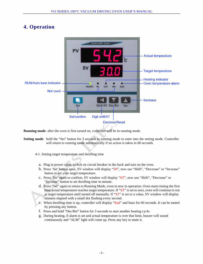
4. Operation
Running mode: after the oven is first turned on, controller will be in running mode. Setting mode: hold the “Set” button for 3 seconds in running mode to enter into the setting mode. Controller
will return to running mode automatically if no action is taken in 60 seconds.
4-1. Setting target temperature and dwelling time
a. Plug in power cable, switch on circuit breaker in the back and turn on the oven. b. Press ‘Set’ button once, SV window will display “SP”, now use “Shift”, “Decrease” or “Increase”
button to set your target temperature. c. Press ‘Set’ again to confirm, SV window will display “ST”, now use “Shift”, “Decrease” or
“Increase” button to set dwelling time in minute. d. Press “Set” again to return to Running Mode, oven in now in operation. Oven starts timing the first
time actual temperature reaches target temperature. If “ST” is set to zero, oven will continue to run at target temperature until turned off manually. If “ST” is set to a value, SV window will display minutes elapsed with a small dot flashing every second.
e. When dwelling time is up, controller will display “End” and buzz for 60 seconds. It can be muted by pressing any button.
f. Press and hold “Dec/Rst” button for 3 seconds to start another heating cycle. g. During heating, if alarm is set and actual temperature is over that limit, buzzer will sound
continuously and “ALM” light will come up. Press any key to mute it.
- 6 -
VO SERIES 100°C VACUUM DRYING OVEN USER’S MANUAL
- 7 -
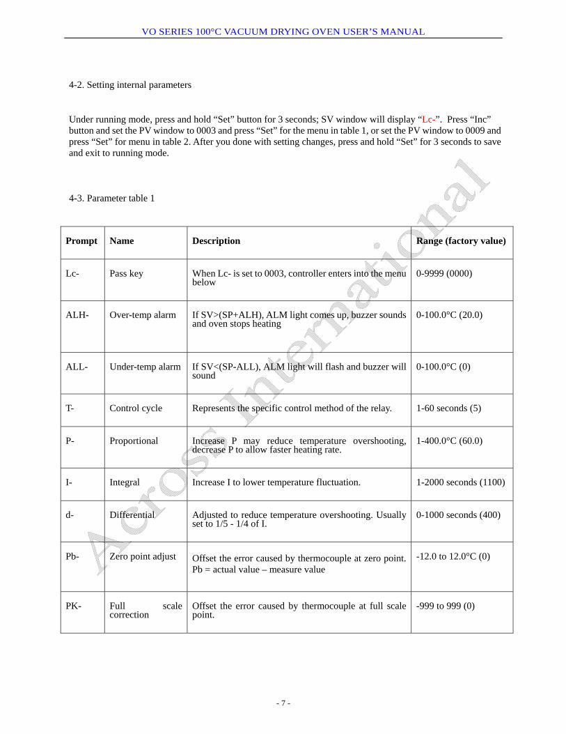
4-2. Setting internal parameters
Under running mode, press and hold “Set” button for 3 seconds; SV window will display “Lc-”. Press “Inc” button and set the PV window to 0003 and press “Set” for the menu in table 1, or set the PV window to 0009 and press “Set” for menu in table 2. After you done with setting changes, press and hold “Set” for 3 seconds to save and exit to running mode.
4-3. Parameter table 1
Prompt Name Description Range (factory value)
Lc- Pass key When Lc- is set to 0003, controller enters into the menu below
0-9999 (0000)
ALH- Over-temp alarm If SV>(SP+ALH), ALM light comes up, buzzer sounds and oven stops heating
0-100.0°C (20.0)
ALL- Under-temp alarm If SV<(SP-ALL), ALM light will flash and buzzer will sound
0-100.0°C (0)
T- Control cycle Represents the specific control method of the relay. 1-60 seconds (5)
P- Proportional Increase P may reduce temperature overshooting, decrease P to allow faster heating rate.
1-400.0°C (60.0)
I- Integral Increase I to lower temperature fluctuation. 1-2000 seconds (1100)
d- Differential Adjusted to reduce temperature overshooting. Usually set to 1/5 - 1/4 of I.
0-1000 seconds (400)
Pb- Zero point adjust Offset the error caused by thermocouple at zero point. Pb = actual value – measure value
-12.0 to 12.0°C (0)
PK- Full scale correction
Offset the error caused by thermocouple at full scale point.
-999 to 999 (0)
VO SERIES 100°C VACUUM DRYING OVEN USER’S MANUAL
- 8 -
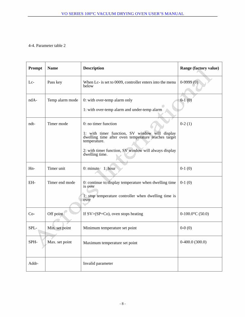
4-4. Parameter table 2
Prompt Name Description Range (factory value)
Lc- Pass key When Lc- is set to 0009, controller enters into the menu below
0-9999 (0)
ndA- Temp alarm mode 0: with over-temp alarm only
1: with over-temp alarm and under-temp alarm
0-1 (0)
ndt- Timer mode 0: no timer function
1: with timer function, SV window will display dwelling time after oven temperature reaches target temperature.
2: with timer function, SV window will always display dwelling time.
0-2 (1)
Hn- Timer unit 0: minute 1: hour 0-1 (0)
EH- Timer end mode 0: continue to display temperature when dwelling time is over
1: stop temperature controller when dwelling time is over
0-1 (0)
Co- Off point If SV>(SP+Co), oven stops heating 0-100.0°C (50.0)
SPL- Min. set point Minimum temperature set point 0-0 (0)
SPH- Max. set point Maximum temperature set point 0-400.0 (300.0)
Addr- Invalid parameter
VO SERIES 100°C VACUUM DRYING OVEN USER’S MANUAL
- 9 -
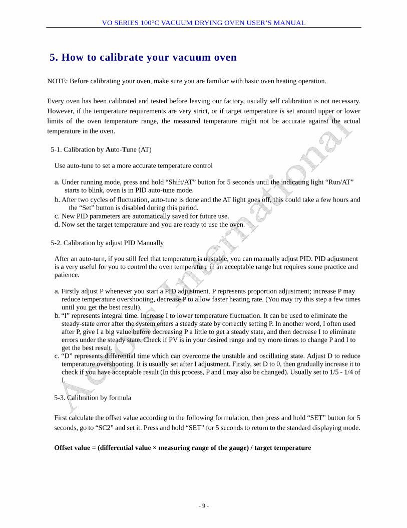
5. How to calibrate your vacuum oven
NOTE: Before calibrating your oven, make sure you are familiar with basic oven heating operation. Every oven has been calibrated and tested before leaving our factory, usually self calibration is not necessary. However, if the temperature requirements are very strict, or if target temperature is set around upper or lower limits of the oven temperature range, the measured temperature might not be accurate against the actual temperature in the oven.
5-1. Calibration by Auto-Tune (AT) Use auto-tune to set a more accurate temperature control a. Under running mode, press and hold “Shift/AT” button for 5 seconds until the indicating light “Run/AT”
starts to blink, oven is in PID auto-tune mode. b. After two cycles of fluctuation, auto-tune is done and the AT light goes off, this could take a few hours and
the “Set” button is disabled during this period. c. New PID parameters are automatically saved for future use. d. Now set the target temperature and you are ready to use the oven.
5-2. Calibration by adjust PID Manually
After an auto-turn, if you still feel that temperature is unstable, you can manually adjust PID. PID adjustment is a very useful for you to control the oven temperature in an acceptable range but requires some practice and patience. a. Firstly adjust P whenever you start a PID adjustment. P represents proportion adjustment; increase P may
reduce temperature overshooting, decrease P to allow faster heating rate. (You may try this step a few times until you get the best result).
b. “I” represents integral time. Increase I to lower temperature fluctuation. It can be used to eliminate the steady-state error after the system enters a steady state by correctly setting P. In another word, I often used after P, give I a big value before decreasing P a little to get a steady state, and then decrease I to eliminate errors under the steady state. Check if PV is in your desired range and try more times to change P and I to get the best result.
c. “D” represents differential time which can overcome the unstable and oscillating state. Adjust D to reduce temperature overshooting. It is usually set after I adjustment. Firstly, set D to 0, then gradually increase it to check if you have acceptable result (In this process, P and I may also be changed). Usually set to 1/5 - 1/4 of I.
5-3. Calibration by formula First calculate the offset value according to the following formulation, then press and hold “SET” button for 5 seconds, go to “SC2” and set it. Press and hold “SET” for 5 seconds to return to the standard displaying mode. Offset value = (differential value × measuring range of the gauge) / target temperature
VO SERIES 100°C VACUUM DRYING OVEN USER’S MANUAL
- 10 -
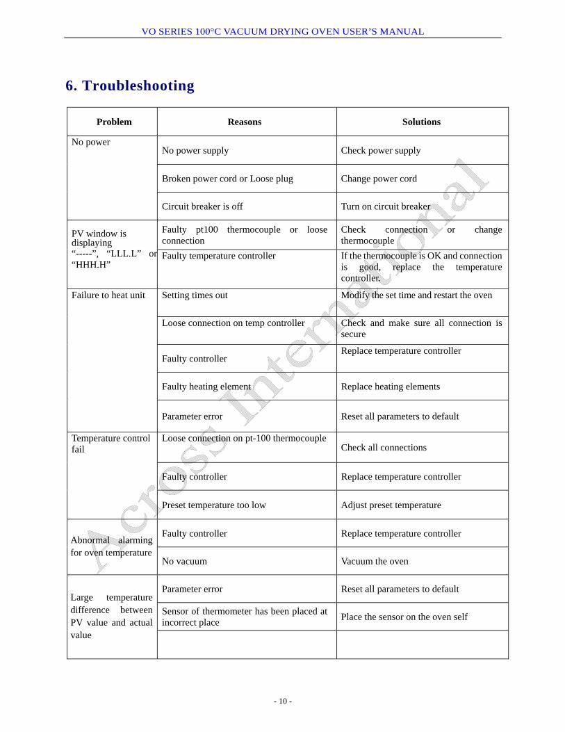
6. Troubleshooting
Problem Reasons Solutions
No power supply Check power supply
Broken power cord or Loose plug Change power cord
No power
Circuit breaker is off Turn on circuit breaker
Faulty pt100 thermocouple or loose connection
Check connection or change thermocouple
PV window is displaying “-----”, “LLL.L” or“HHH.H”
Faulty temperature controller If the thermocouple is OK and connection is good, replace the temperature controller.
Setting times out Modify the set time and restart the oven
Loose connection on temp controller Check and make sure all connection is secure
Faulty controller Replace temperature controller
Faulty heating element Replace heating elements
Failure to heat unit
Parameter error Reset all parameters to default
Loose connection on pt-100 thermocouple Check all connections
Faulty controller Replace temperature controller
Temperature control fail
Preset temperature too low Adjust preset temperature
Faulty controller Replace temperature controller Abnormal alarming for oven temperature
No vacuum Vacuum the oven
Parameter error Reset all parameters to default
Sensor of thermometer has been placed at incorrect place Place the sensor on the oven self
Large temperature difference between PV value and actual value
VO SERIES 100°C VACUUM DRYING OVEN USER’S MANUAL
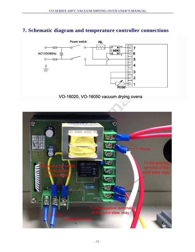
7. Schematic diagram and temperature controller connections
- 11 -