Embed Size (px)
Citation preview

ENService manual 2016
ACP-12CH35AEYI
CONTENTS
1. Precaution .................................................................................................................................................... 3 1.1 Safety Precaution .......................................................................................................................... 3 1.2 Warning ......................................................................................................................................... 3
2. Function ........................................................................................................................................................ 7 3. Dimension .................................................................................................................................................... 8
3.1 Indoor Unit ..................................................................................................................................... 8 3.2 Outdoor Unit .................................................................................................................................. 9
4. Refrigerant Cycle Diagram ....................................................................................................................... 10 5. Wiring Diagram ........................................................................................................................................... 11
5.1 Indoor Unit .................................................................................................................................... 11 5.2 Outdoor Unit ................................................................................................................................ 12
6 Installation Details ...................................................................................................................................... 13 6.1 Wrench torque sheet for installation ........................................................................................... 13 6.2 Connecting the cables ................................................................................................................ 13 6.3 Pipe length and the elevation ..................................................................................................... 14 6.4 Installation for the first time ......................................................................................................... 15 6.5 Adding the refrigerant after running the system for many years ................................................ 19 6.6 Re-installation while the indoor unit need to be repaired ........................................................... 20 6.7 Re-installation while the outdoor unit need to be repaired ......................................................... 22
7. Operation Characteristics ......................................................................................................................... 25 8. Electronic function .................................................................................................................................... 26
8.1 Abbreviation ................................................................................................................................ 26 8.2 Display function ........................................................................................................................... 26 8.3 Main Protection ........................................................................................................................... 27 8.4 Operation Modes and Functions ................................................................................................. 29
9. Troubleshooting ......................................................................................................................................... 44 9.1 Indoor Unit Error Display ............................................................................................................. 44 9.2 Diagnosis and Solution ............................................................................................................... 45
3
1. Precaution
1.1 Safety Precaution
To prevent injury to the user or other people and property damage, the following
instructions must be followed.
Incorrect operation due to ignoring instruction will cause harm or damage.
Before service the unit, be sure to read this service manual at first.
1.2 Warning
Installation
Do not use a defective or underrated circuit breaker. Use this appliance on a dedicated
circuit.
There is risk of fire or electric shock.
For electrical work, contact the dealer, seller, a qualified electrician, or an authorized
service center.
Do not disassemble or repair the product, there is risk of fire or electric shock.
Always ground the product.
There is risk of fire or electric shock.
Install the panel and the cover of control box securely.
There is risk of fire of electric shock.
Always install a dedicated circuit and breaker.
Improper wiring or installation may cause fore or electric shock.
Use the correctly rated breaker of fuse.
There is risk of fire or electric shock.
Do not modify or extend the power cable.
There is risk of fire or electric shock.
Do not install, remove, or reinstall the unit by yourself (customer).
There is risk of fire, electric shock, explosion, or injury.
Be caution when unpacking and installing the product.
Sharp edges could cause injury, be especially careful of the case edges and the fins on the
4
condenser and evaporator.
For installation, always contact the dealer or an authorized service center.
Do not install the product on a defective installation stand.
Be sure the installation area does not deteriorate with age.
If the base collapses, the air conditioner could fall with it, causing property damage, product failure,
and personal injury.
Do not let the air conditioner run for a long time when the humidity is very high and a
door or a window is left open.
Take care to ensure that power cable could not be pulled out or damaged during
operation.
There is risk of fire or electric shock.
Do not place anything on the power cable.
There is risk of fire or electric shock.
Do not plug or unplug the power supply plug during operation.
There is risk of fire or electric shock.
Do not touch (operation) the product with wet hands.
Do not place a heater or other appliance near the power cable.
There is risk of fire and electric shock.
Do not allow water to run into electrical parts.
It may cause fire, failure of the product, or electric shock.
Do not store or use flammable gas or combustible near the product.
There is risk of fire or failure of product.
Do not use the product in a tightly closed space for a long time.
Oxygen deficiency could occur.
When flammable gas leaks, turn off the gas and open a window for ventilation before
turn the product on.
If strange sounds or smoke comes from product, turn the breaker off or disconnect the
power supply cable.
There is risk of electric shock or fire.
Stop operation and close the window in storm or hurricane. If possible, remove the
product from the window before the hurricane arrives.
5
There is risk of property damage, failure of product, or electric shock.
Do not open the inlet grill of the product during operation. (Do not touch the
electrostatic filter, if the unit is so equipped.)
There is risk of physical injury, electric shock, or product failure.
When the product is soaked, contact an authorized service center.
There is risk of fire or electric shock.
Be caution that water could not enter the product.
There is risk of fire, electric shock, or product damage.
Ventilate the product from time to time when operating it together with a stove etc.
There is risk of fire or electric shock.
Turn the main power off when cleaning or maintaining the product.
There is risk of electric shock.
When the product is not be used for a long time, disconnect the power supply plug or
turn off the breaker.
There is risk of product damage or failure, or unintended operation.
Take care to ensure that nobody could step on or fall onto the outdoor unit.
This could result in personal injury and product damage.
CAUTION
Always check for gas (refrigerant) leakage after installation or repair of product.
Low refrigerant levels may cause failure of product.
Install the drain hose to ensure that water is drained away properly.
A bad connection may cause water leakage.
Keep level even when installing the product.
It can avoid vibration of water leakage.
Do not install the product where the noise or hot air from the outdoor unit could
damage the neighborhoods.
It may cause a problem for your neighbors.
Use two or more people to lift and transport the product.
Do not install the product where it will be exposed to sea wind (salt spray) directly.
It may cause corrosion on the product. Corrosion, particularly on the condenser and evaporator
6
fins, could cause product malfunction or inefficient operation.
Operational
Do not expose the skin directly to cool air for long time. (Do not sit in the draft).
Do not use the product for special purposes, such as preserving foods, works of art
etc. It is a consumer air conditioner, not a precision refrigerant system.
There is risk of damage or loss of property.
Do not block the inlet or outlet of air flow.
Use a soft cloth to clean. Do not use harsh detergents, solvents, etc.
There is risk of fire, electric shock, or damage to the plastic parts of the product.
Do not touch the metal parts of the product when removing the air filter. They are very
sharp.
Do not step on or put anything on the product. (outdoor units)
Always insert the filter securely. Clean the filter every two weeks or more often if
necessary.
A dirty filter reduces the efficiency of the air conditioner and could cause product malfunction or
damage.
Do not insert hands or other objects through air inlet or outlet while the product is
operated.
Do not drink the water drained from the product.
Use a firm stool or ladder when cleaning or maintaining the product.
Be careful and avoid personal injury.
Replace the all batteries in the remote control with new ones of the same type. Do not
mix old and new batteries or different types of batteries.
There is risk of fire or explosion.
Do not recharge or disassemble the batteries. Do not dispose of batteries in a fire.
They may burn of explode.
If the liquid from the batteries gets onto your skin or clothes, wash it well with clean
water. Do not use the remote of the batteries have leaked.
7
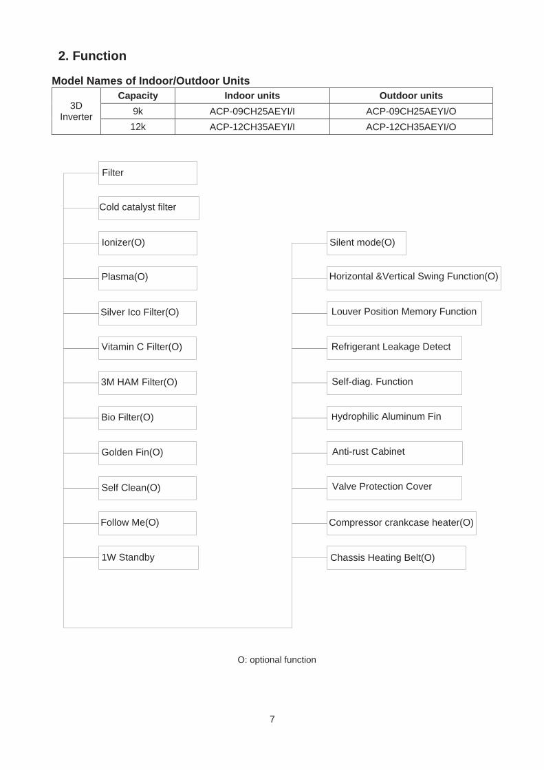
2. Function
Model Names of Indoor/Outdoor Units
3D Inverter
Capacity Indoor units Outdoor units 9k ACP-09CH25AEYI/I ACP-09CH25AEYI/O 12k ACP-12CH35AEYI/I ACP-12CH35AEYI/O
Cold catalyst filter
Plasma(O)
Silver Ico Filter(O)
Vitamin C Filter(O)
3M HAM Filter(O)
Bio Filter(O)
Golden Fin(O)
Ionizer(O)
Self Clean(O)
1W Standby
Louver Position Memory Function
Refrigerant Leakage Detect
Self-diag. Function
Hydrophilic Aluminum Fin
Anti-rust Cabinet
Valve Protection Cover
Chassis Heating Belt(O)
Horizontal &Vertical Swing Function(O)
Filter
Follow Me(O)
Silent mode(O)
Compressor crankcase heater(O)
O: optional function
8
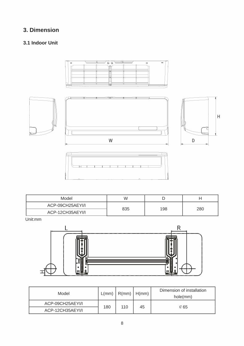
3. Dimension
3.1 Indoor Unit
W D
Unit:mm
Model L(mm) R(mm) H(mm) Dimension of installation
hole(mm) ACP-09CH25AEYI/I
180 110 45 65 ACP-12CH35AEYI/I
Model W D H ACP-09CH25AEYI/I
835 198 280 ACP-12CH35AEYI/I
9
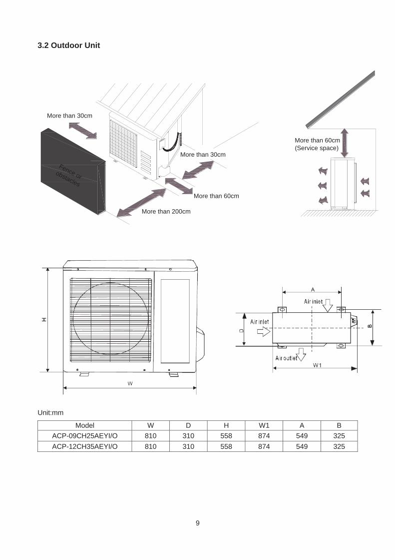
3.2 Outdoor Unit
More than 30cm
More than 60cm
More than 200cm
More than 30cm
More than 60cm(Service space
Fence orobstacles
Unit:mm
Model W D H W1 A B ACP-09CH25AEYI/O 810 310 558 874 549 325 ACP-12CH35AEYI/O 810 310 558 874 549 325
10
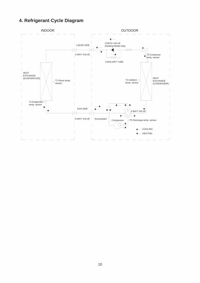
4. Refrigerant Cycle Diagram
CHECK VALVE(Heating Model only)
CAPILIARY TUBE
LIQUID SIDE
GAS SIDE
HEAT EXCHANGE(EVAPORATOR) HEAT
EXCHANGE(CONDENSER)
Compressor
2-WAY VALVE
3-WAY VALVE
4-WAY VALVE
COOLING
HEATING
T2 Evaporator temp. sensor
T1 Room temp. sensor
T3 Condenser temp. sensor
Accumulator T5 Discharge temp. sensor
T4 Ambient temp. sensor
INDOOR OUTDOOR
11
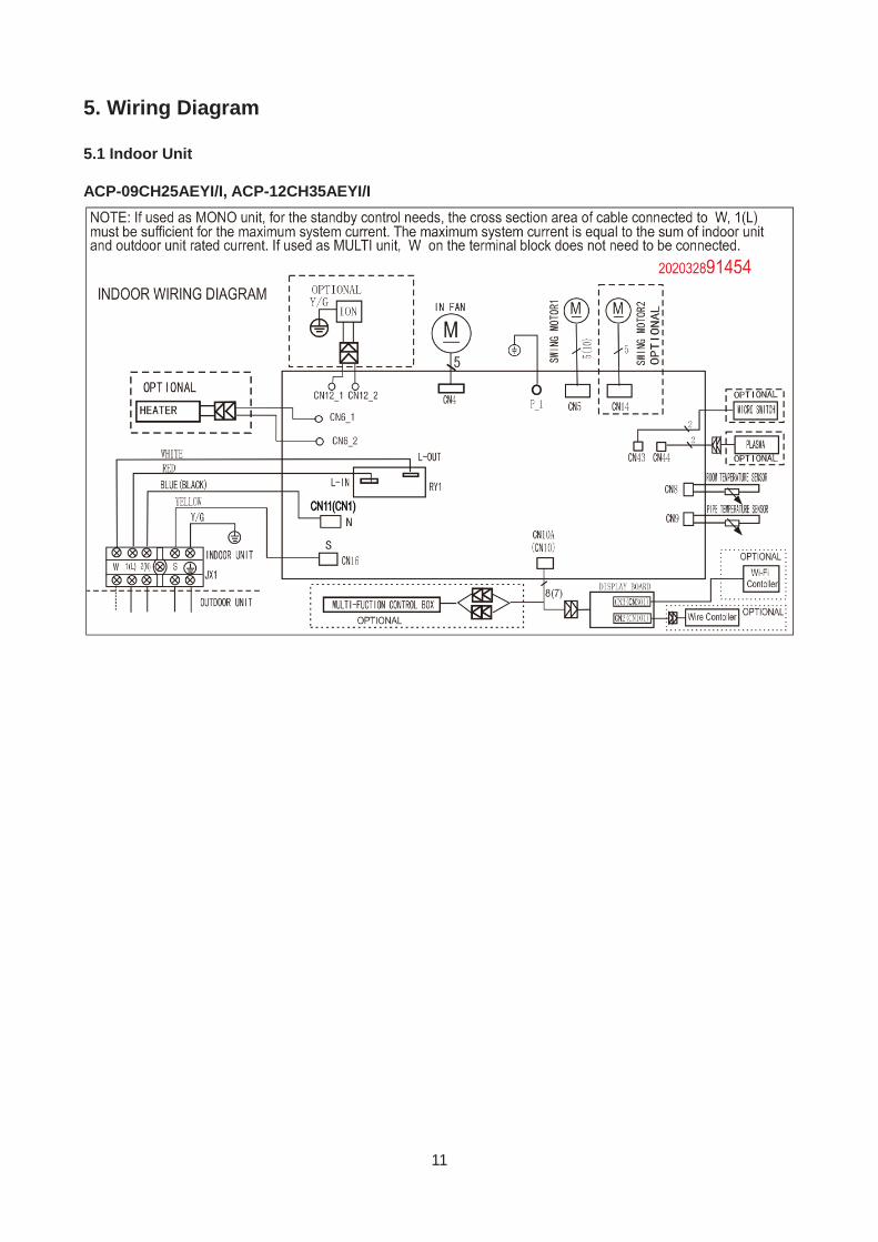
5. Wiring Diagram
5.1 Indoor Unit
ACP-09CH25AEYI/I, ACP-12CH35AEYI/I
12
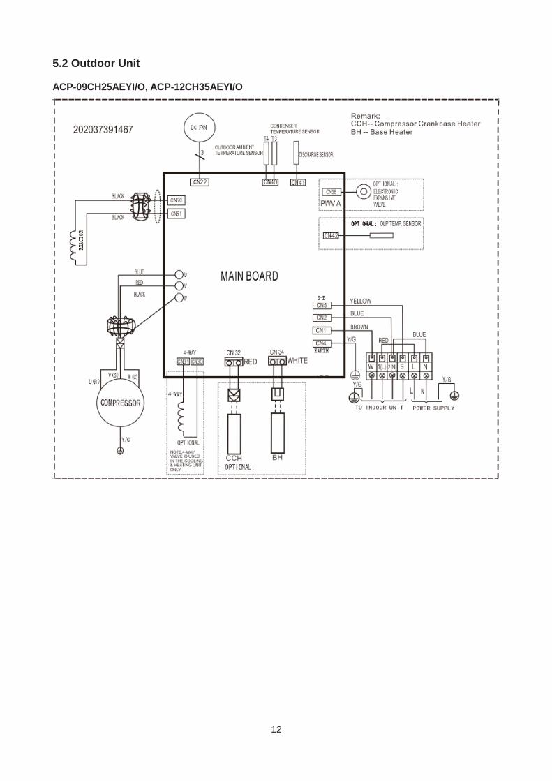
5.2 Outdoor Unit
ACP-09CH25AEYI/O, ACP-12CH35AEYI/O
13
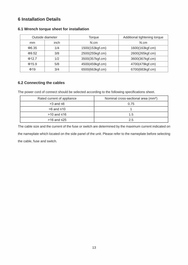
6 Installation Details
6.1 Wrench torque sheet for installation
Outside diameter Torque Additional tightening torque mm inch N.cm N.cm Ф6.35 1/4 1500(153kgf.cm) 1600(163kgf.cm) Ф9.52 3/8 2500(255kgf.cm) 2600(265kgf.cm) Ф12.7 1/2 3500(357kgf.cm) 3600(367kgf.cm) Ф15.9 5/8 4500(459kgf.cm) 4700(479kgf.cm) Ф19 3/4 6500(663kgf.cm) 6700(683kgf.cm)
6.2 Connecting the cables
The power cord of connect should be selected according to the following specifications sheet.
Rated current of appliance Nominal cross-sectional area (mm²) >3 and ≤6 0.75 >6 and ≤10 1 >10 and ≤16 1.5 >16 and ≤25 2.5
The cable size and the current of the fuse or switch are determined by the maximum current indicated on
the nameplate which located on the side panel of the unit. Please refer to the nameplate before selecting
the cable, fuse and switch.
14
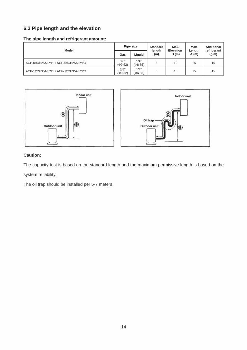
6.3 Pipe length and the elevation
The pipe length and refrigerant amount:
Model Pipe size Standard
length (m)
Max. Elevation
B (m)
Max. Length A (m)
Additional refrigerant
(g/m) Gas Liquid
ACP-09CH25AEYI/I + ACP-09CH25AEYI/O 3/8’’ (Ф9.52)
1/4’’ (Ф6.35) 5 10 25 15
ACP-12CH35AEYI/I + ACP-12CH35AEYI/O 3/8’’ (Ф9.52)
1/4’’ (Ф6.35) 5 10 25 15
Caution:
The capacity test is based on the standard length and the maximum permissive length is based on the
system reliability.
The oil trap should be installed per 5-7 meters.
15
6.4 Installation for the first time
Air and moisture in the refrigerant system have undesirable effects as below:
Pressure in the system rises.
Operating current rises.
Cooling or heating efficiency drops.
Moisture in the refrigerant circuit may freeze and block capillary tubing.
Water may lead to corrosion of parts in the refrigerant system.
Therefore, the indoor units and the pipes between indoor and outdoor units must be leak tested and
evacuated to remove gas and moisture from the system.
Gas leak check (Soap water method):
Apply soap water or a liquid neutral detergent on the indoor unit connections or outdoor unit
connections by a soft brush to check for leakage of the connecting points of the piping. If bubbles come
out, the pipes have leakage.
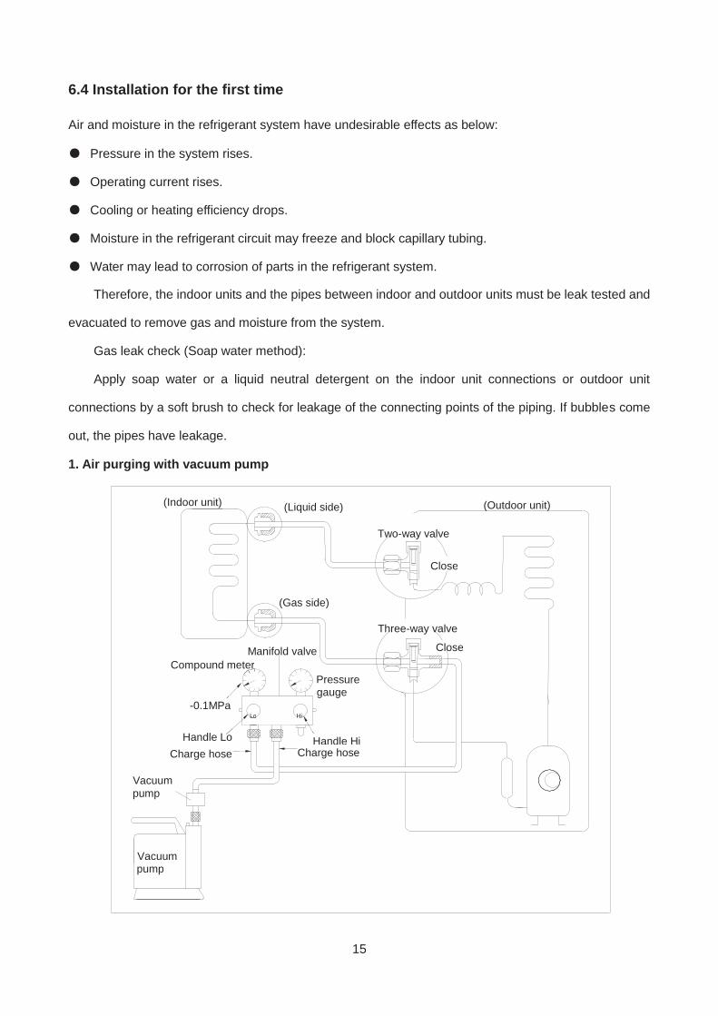
1. Air purging with vacuum pump
(Indoor unit) (Liquid side)
(Gas side)
Vacuum Vacuupump
Vacuum Vacuu pump
Lo Hi
Handle Hi
Two-way valve
Close
Manifold valve Compound meter
Pressure Pressugauge
-0.1MPa
Handle Lo Charge hose
Handle HiCharge hose
(Outdoor unit)
Close
Three-way valve
16
1) Completely tighten the flare nuts of the indoor and outdoor units, confirm that both the 2-way and 3-
way valves are set to the closed position.
2) Connect the charge hose with the push pin of handle lo to the 3-way valves gas service port..
3) Connect the charge hose of handle hi connection to the vacuum pump.
4) Fully open the handle Lo of the manifold valve.
5) Operate the vacuum pump to evacuate.
6) Make evacuation for 30 minutes and check whether the compound meter indicates -0.1Mpa. If the
meter does not indicate -0.1Mpa after pumping 30 minutes, it should be pumped 20 minutes more. If
the pressure can’t achieve -0.1Mpa after pumping 50 minutes, please check if there are some leakage
points.
Fully close the handle Lo valve of the manifold valve and stop the operation of the vacuum pump. Confirm
that the gauge needle does not move (approximately 5 minutes after turning off the vacuum pump).
7) Turn the flare nut of the 3-way valves about 45° counterclockwise for 6 or 7seconds after the gas
coming out, then tighten the flare nut again. Make sure the pressure display in the pressure indicator is
a little higher than the atmosphere pressure. Then remove the charge hose from the 3 way valve.
8) Fully open the 2 way valve and 3 way valve and securely tighten the cap of the 3 way valve.
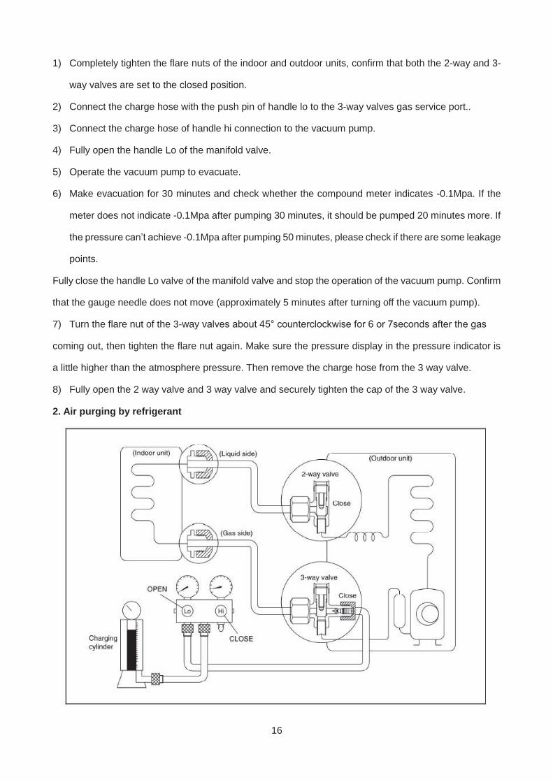
2. Air purging by refrigerant
17
Procedure:
1). Confirm that both the 2-way and 3-way valves are set to the closed position.
2). Connect the charge set and a charging cylinder to the service port of the 3-way valve.
3). Air purging.
Open the valves on the charging cylinder and the charge set. Purge the air by loosening the flare nut on
the 2-way valve approximately 45’ for 3 seconds then closing it for 1 minute; repeat 3 times.
After purging the air, use a torque wrench to tighten the flare nut on the 2-way valve.
4). Check the gas leakage.
Check the flare connections for gas leakage.
5). Discharge the refrigerant.
Close the valve on the charging cylinder and discharge the refrigerant by loosening the flare nut on the
2-way valve approximately 45’ until the gauge indicates 0.3 to 0.5 Mpa.
6). Disconnect the charge set and the charging cylinder, and set the 2-way and 3-way valves to the
open position.
Be sure to use a hexagonal wrench to operate the valve stems.
7). Mount the valve stems nuts and the service port cap.
Be sure to use a torque wrench to tighten the service port cap to a torque 18N·m.
Be sure to check the gas leakage.
3. Adding the refrigerant if the pipe length >5m
18
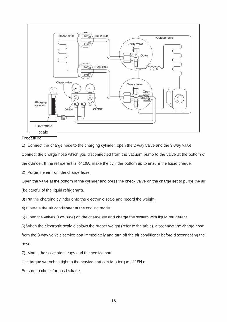
Procedure:
1). Connect the charge hose to the charging cylinder, open the 2-way valve and the 3-way valve.
Connect the charge hose which you disconnected from the vacuum pump to the valve at the bottom of
the cylinder. If the refrigerant is R410A, make the cylinder bottom up to ensure the liquid charge.
2). Purge the air from the charge hose.
Open the valve at the bottom of the cylinder and press the check valve on the charge set to purge the air
(be careful of the liquid refrigerant).
3) Put the charging cylinder onto the electronic scale and record the weight.
4) Operate the air conditioner at the cooling mode.
5) Open the valves (Low side) on the charge set and charge the system with liquid refrigerant.
6).When the electronic scale displays the proper weight (refer to the table), disconnect the charge hose
from the 3-way valve’s service port immediately and turn off the air conditioner before disconnecting the
hose.
7). Mount the valve stem caps and the service port
Use torque wrench to tighten the service port cap to a torque of 18N.m.
Be sure to check for gas leakage.
Electronic scale
19
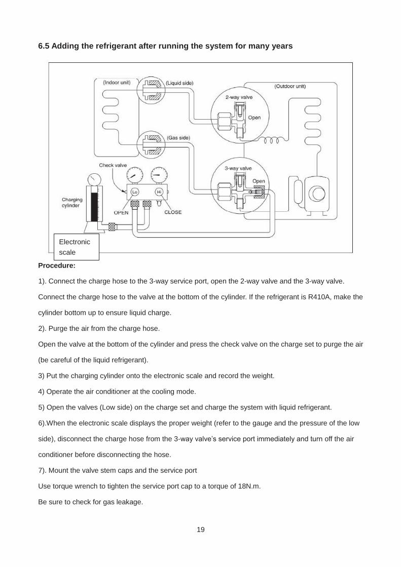
6.5 Adding the refrigerant after running the system for many years
Procedure:
1). Connect the charge hose to the 3-way service port, open the 2-way valve and the 3-way valve.
Connect the charge hose to the valve at the bottom of the cylinder. If the refrigerant is R410A, make the
cylinder bottom up to ensure liquid charge.
2). Purge the air from the charge hose.
Open the valve at the bottom of the cylinder and press the check valve on the charge set to purge the air
(be careful of the liquid refrigerant).
3) Put the charging cylinder onto the electronic scale and record the weight.
4) Operate the air conditioner at the cooling mode.
5) Open the valves (Low side) on the charge set and charge the system with liquid refrigerant.
6).When the electronic scale displays the proper weight (refer to the gauge and the pressure of the low
side), disconnect the charge hose from the 3-way valve’s service port immediately and turn off the air
conditioner before disconnecting the hose.
7). Mount the valve stem caps and the service port
Use torque wrench to tighten the service port cap to a torque of 18N.m.
Be sure to check for gas leakage.
Electronic scale
20
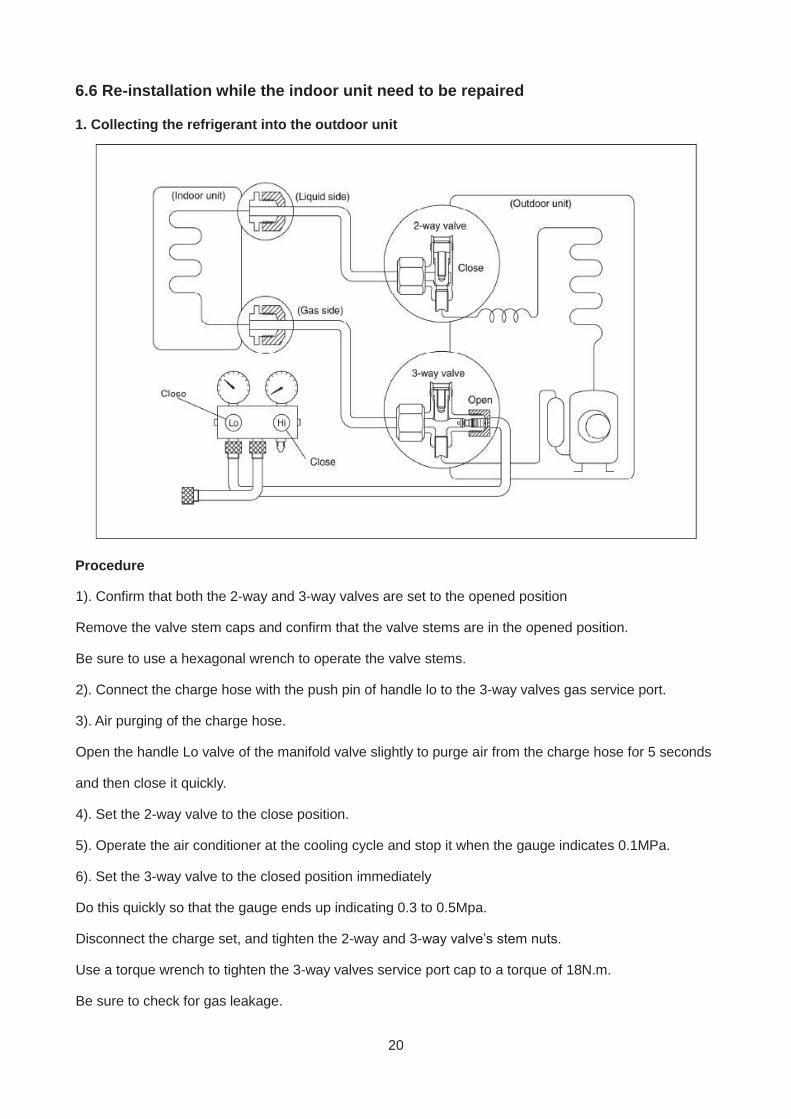
6.6 Re-installation while the indoor unit need to be repaired
1. Collecting the refrigerant into the outdoor unit
Procedure
1). Confirm that both the 2-way and 3-way valves are set to the opened position
Remove the valve stem caps and confirm that the valve stems are in the opened position.
Be sure to use a hexagonal wrench to operate the valve stems.
2). Connect the charge hose with the push pin of handle lo to the 3-way valves gas service port.
3). Air purging of the charge hose.
Open the handle Lo valve of the manifold valve slightly to purge air from the charge hose for 5 seconds
and then close it quickly.
4). Set the 2-way valve to the close position.
5). Operate the air conditioner at the cooling cycle and stop it when the gauge indicates 0.1MPa.
6). Set the 3-way valve to the closed position immediately
Do this quickly so that the gauge ends up indicating 0.3 to 0.5Mpa.
Disconnect the charge set, and tighten the 2-way and 3-way valve’s stem nuts.
Use a torque wrench to tighten the 3-way valves service port cap to a torque of 18N.m.
Be sure to check for gas leakage.
21
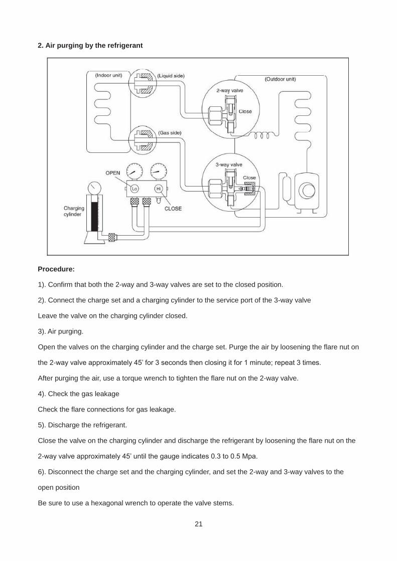
2. Air purging by the refrigerant
Procedure:
1). Confirm that both the 2-way and 3-way valves are set to the closed position.
2). Connect the charge set and a charging cylinder to the service port of the 3-way valve
Leave the valve on the charging cylinder closed.
3). Air purging.
Open the valves on the charging cylinder and the charge set. Purge the air by loosening the flare nut on
the 2-way valve approximately 45’ for 3 seconds then closing it for 1 minute; repeat 3 times.
After purging the air, use a torque wrench to tighten the flare nut on the 2-way valve.
4). Check the gas leakage
Check the flare connections for gas leakage.
5). Discharge the refrigerant.
Close the valve on the charging cylinder and discharge the refrigerant by loosening the flare nut on the
2-way valve approximately 45’ until the gauge indicates 0.3 to 0.5 Mpa.
6). Disconnect the charge set and the charging cylinder, and set the 2-way and 3-way valves to the
open position
Be sure to use a hexagonal wrench to operate the valve stems.
22
7). Mount the valve stems nuts and the service port cap
Be sure to use a torque wrench to tighten the service port cap to a torque 18N.m.
Be sure to check the gas leakage.
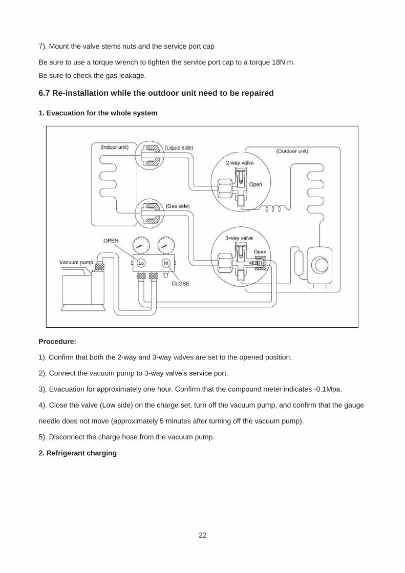
6.7 Re-installation while the outdoor unit need to be repaired
1. Evacuation for the whole system
Procedure:
1). Confirm that both the 2-way and 3-way valves are set to the opened position.
2). Connect the vacuum pump to 3-way valve’s service port.
3). Evacuation for approximately one hour. Confirm that the compound meter indicates -0.1Mpa.
4). Close the valve (Low side) on the charge set, turn off the vacuum pump, and confirm that the gauge
needle does not move (approximately 5 minutes after turning off the vacuum pump).
5). Disconnect the charge hose from the vacuum pump.
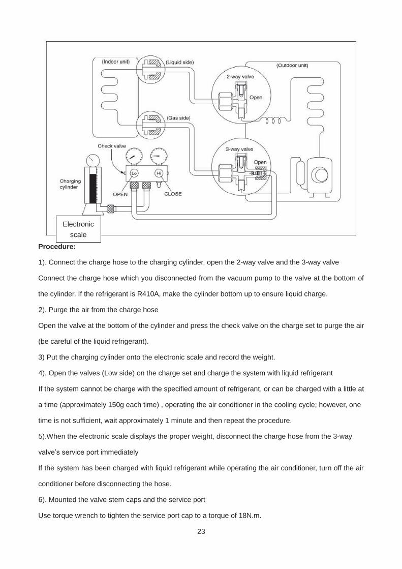
2. Refrigerant charging
23
Procedure:
1). Connect the charge hose to the charging cylinder, open the 2-way valve and the 3-way valve
Connect the charge hose which you disconnected from the vacuum pump to the valve at the bottom of
the cylinder. If the refrigerant is R410A, make the cylinder bottom up to ensure liquid charge.
2). Purge the air from the charge hose
Open the valve at the bottom of the cylinder and press the check valve on the charge set to purge the air
(be careful of the liquid refrigerant).
3) Put the charging cylinder onto the electronic scale and record the weight.
4). Open the valves (Low side) on the charge set and charge the system with liquid refrigerant
If the system cannot be charge with the specified amount of refrigerant, or can be charged with a little at
a time (approximately 150g each time) , operating the air conditioner in the cooling cycle; however, one
time is not sufficient, wait approximately 1 minute and then repeat the procedure.
5).When the electronic scale displays the proper weight, disconnect the charge hose from the 3-way
valve’s service port immediately
If the system has been charged with liquid refrigerant while operating the air conditioner, turn off the air
conditioner before disconnecting the hose.
6). Mounted the valve stem caps and the service port
Use torque wrench to tighten the service port cap to a torque of 18N.m.
Electronic scale

24
Be sure to check for gas leakage
25
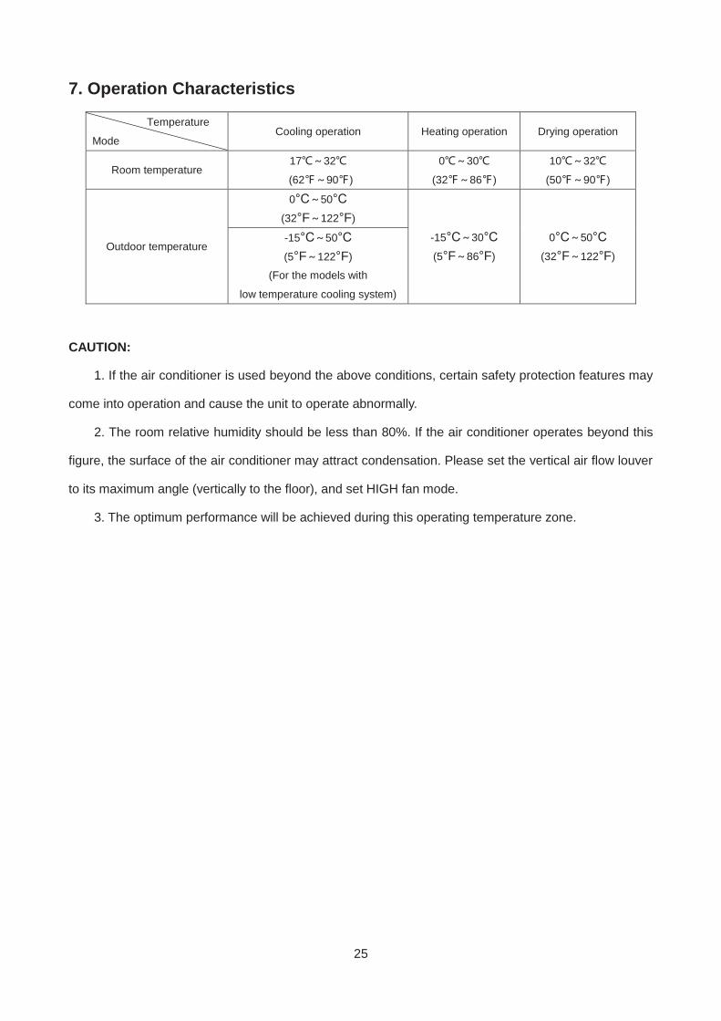
7. Operation Characteristics
Temperature
Mode Cooling operation Heating operation Drying operation
Room temperature 17 32
(62 90 )
0 30
(32 86 )
10 32
(50 90 )
Outdoor temperature
0°C 50°C
(32°F 122°F)
-15°C 30°C
(5°F 86°F)
0°C 50°C
(32°F 122°F)
-15°C 50°C
(5°F 122°F)
(For the models with
low temperature cooling system)
CAUTION:
1. If the air conditioner is used beyond the above conditions, certain safety protection features may
come into operation and cause the unit to operate abnormally.
2. The room relative humidity should be less than 80%. If the air conditioner operates beyond this
figure, the surface of the air conditioner may attract condensation. Please set the vertical air flow louver
to its maximum angle (vertically to the floor), and set HIGH fan mode.
3. The optimum performance will be achieved during this operating temperature zone.
26
8. Electronic function
8.1 Abbreviation
T1: Indoor room temperature
T2: Coil temperature of evaporator
T3: Coil temperature of condenser
T4: Outdoor ambient temperature
T5: Compressor discharge temperature
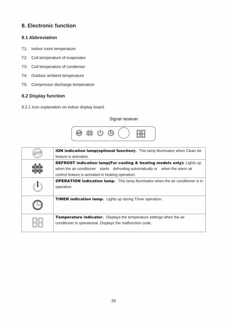
8.2 Display function
8.2.1 Icon explanation on indoor display board.
ION indication lamp(optional function) This lamp illuminates when Clean Air feature is activated.
DEFROST indication lamp(For cooling & heating models only): Lights up when the air conditioner starts defrosting automatically or when the warm air control feature is activated in heating operation.
OPERATION indication lamp This lamp illuminates when the air conditioner is in operation.
TIMER indication lamp Lights up during Timer operation.
Temperature indicator Displays the temperature settings when the air conditioner is operational. Displays the malfunction code.
27
8.3 Main Protection
8.3.1 Time delay at restart for compressor
1 minute delay for the 1st time start-up and 3 minutes delay for others.
8.3.2 Temperature protection of compressor top
The unit will stop working when the compressor top temp. protector cut off, and will restart after the
compressor top temp. protector restart.
8.3.3 Temperature protection of compressor discharge
When the compressor discharge temp. is getting higher, the running frequency will be limited as below
rules:
---Compressor discharge temp. T5>115 for 5s, compressor stops and restarts up till T5<90
---110<T5<115 , decrease the frequency to the lower level every 2 minutes.
---105<T5<110 , keep running at the current frequency.
----T5<105 , no limit for frequency.
8.3.4 Fan speed is out of control
When indoor fan speed keeps too low (300RPM) for certain time, the unit will stop and the LED will display
the failure.
8.3.5 Inverter module protection
The Inverter module has a protection function about current, voltage and temperature. If these protections
happen, the corresponding code will display on indoor unit and the unit will stop working.
8.3.6 Indoor fan delayed open function
When the unit starts up, the louver will be active immediately and the indoor fan will open 10s later.
If the unit runs in heating mode, the indoor fan will be also controlled by anti-cold wind function.
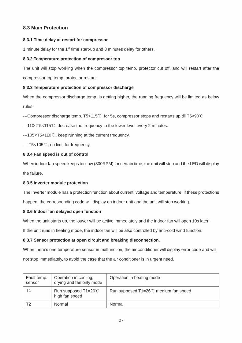
8.3.7 Sensor protection at open circuit and breaking disconnection.
When there’s one temperature sensor in malfunction, the air conditioner will display error code and will
not stop immediately, to avoid the case that the air conditioner is in urgent need.
Fault temp. sensor
Operation in cooling, drying and fan only mode
Operation in heating mode
T1 Run supposed T1=26 high fan speed
Run supposed T1=26 medium fan speed
T2 Normal Normal
28
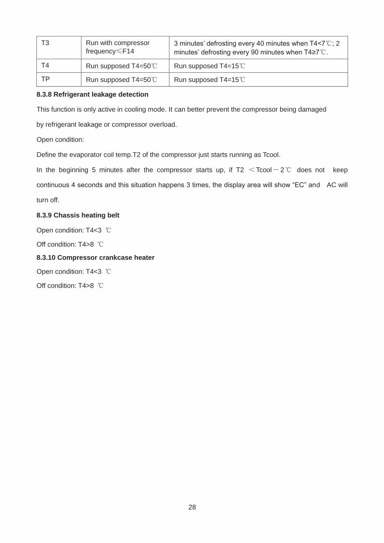
T3 Run with compressor frequency F14
3 minutes’ defrosting every 40 minutes when T4<7 ; 2 minutes’ defrosting every 90 minutes when T4≥7 .
T4 Run supposed T4=50 Run supposed T4=15
TP Run supposed T4=50 Run supposed T4=15
8.3.8 Refrigerant leakage detection
This function is only active in cooling mode. It can better prevent the compressor being damaged
by refrigerant leakage or compressor overload.
Open condition:
Define the evaporator coil temp.T2 of the compressor just starts running as Tcool.
In the beginning 5 minutes after the compressor starts up, if T2 Tcool 2 does not keep
continuous 4 seconds and this situation happens 3 times, the display area will show “EC” and AC will
turn off.
8.3.9 Chassis heating belt
Open condition: T4<3
Off condition: T4>8
8.3.10 Compressor crankcase heater
Open condition: T4<3
Off condition: T4>8
29
8.4 Operation Modes and Functions
8.4.1 Fan mode
(1) Outdoor fan and compressor stop.
(2) Temperature setting function is disabled, and no setting temperature is displayed.
(3) Indoor fan can be set to high/med/low/auto.
(4) The louver operates same as in cooling mode.
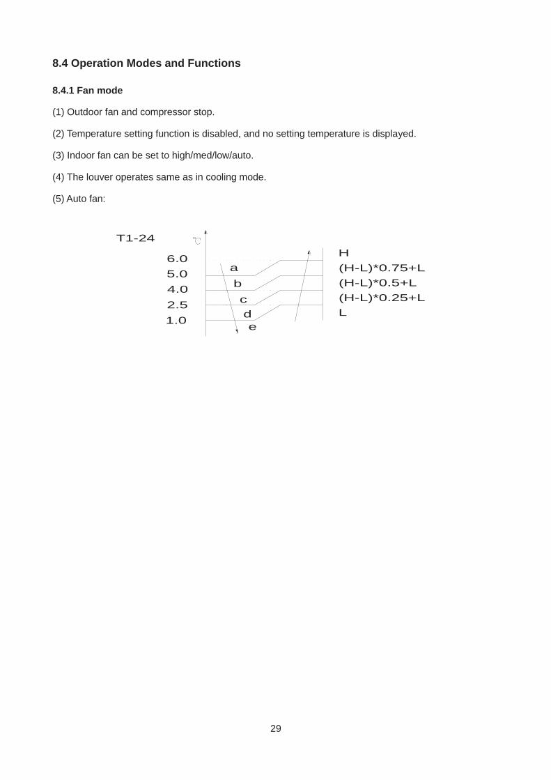
(5) Auto fan:
abcd
5.04.02.51.0
6.0
T1-24
e
H(H-L)*0.75+L(H-L)*0.5+L(H-L)*0.25+LL
30
8.4.2 Cooling Mode
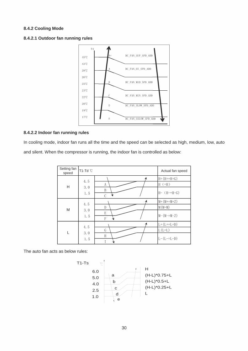
8.4.2.1 Outdoor fan running rules
8.4.2.2 Indoor fan running rules
In cooling mode, indoor fan runs all the time and the speed can be selected as high, medium, low, auto
and silent. When the compressor is running, the indoor fan is controlled as below:
Setting fanspeed Actual fan speedT1-Td
L
H
M
The auto fan acts as below rules:
abcd
5.04.02.51.0
6.0
T1-Ts
e
H(H-L)*0.75+L(H-L)*0.5+L(H-L)*0.25+LL
31
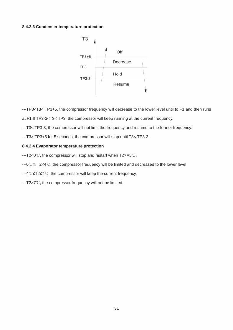
8.4.2.3 Condenser temperature protection
TP3+5
T3
Resume
Off
DecreaseTP3
TP3-3Hold
---TP3<T3< TP3+5, the compressor frequency will decrease to the lower level until to F1 and then runs
at F1.If TP3-3<T3< TP3, the compressor will keep running at the current frequency.
---T3< TP3-3, the compressor will not limit the frequency and resume to the former frequency.
---T3> TP3+5 for 5 seconds, the compressor will stop until T3< TP3-3.
8.4.2.4 Evaporator temperature protection
---T2<0 , the compressor will stop and restart when T2>=5 .
---0 T2<4 , the compressor frequency will be limited and decreased to the lower level
---4 ≤T2≤7 , the compressor will keep the current frequency.
---T2>7 , the compressor frequency will not be limited.
32
8.4.3 Heating Mode
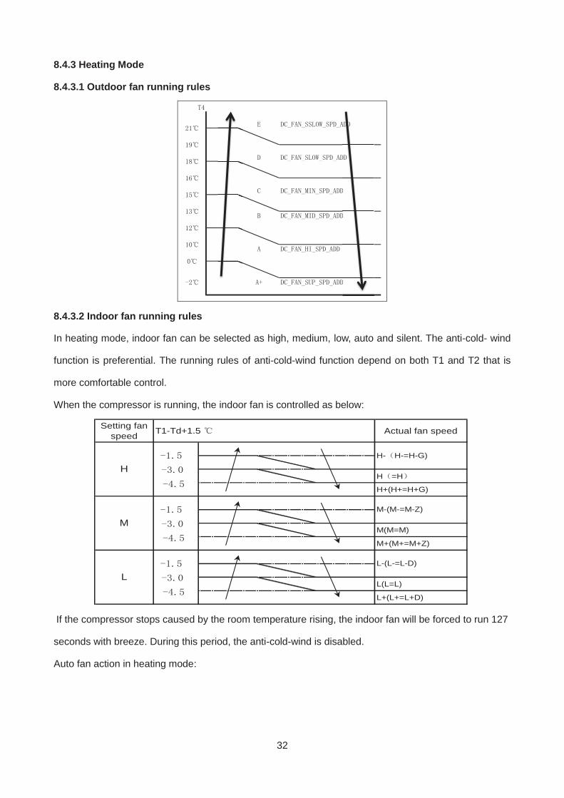
8.4.3.1 Outdoor fan running rules
8.4.3.2 Indoor fan running rules
In heating mode, indoor fan can be selected as high, medium, low, auto and silent. The anti-cold- wind
function is preferential. The running rules of anti-cold-wind function depend on both T1 and T2 that is
more comfortable control.
When the compressor is running, the indoor fan is controlled as below:
Setting fanspeed Actual fan speed
H =H
H+(H+=H+G)
M(M=M)
M+(M+=M+Z)
L(L=L)
L+(L+=L+D)
H- H-=H-G)
M-(M-=M-Z)
L-(L-=L-D)
T1-Td+1.5
L
H
M
If the compressor stops caused by the room temperature rising, the indoor fan will be forced to run 127
seconds with breeze. During this period, the anti-cold-wind is disabled.
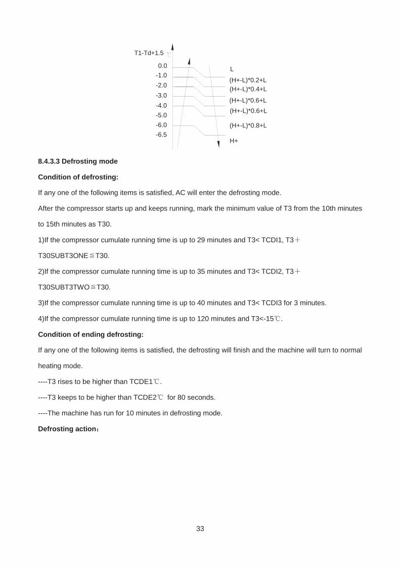
Auto fan action in heating mode:
33
-1.0-2.0-3.0-4.0
0.0
T1-Td+1.5
L
(H+-L)*0.4+L
(H+-L)*0.6+L-5.0-6.0-6.5
H+
(H+-L)*0.8+L
(H+-L)*0.6+L
(H+-L)*0.2+L
8.4.3.3 Defrosting mode
Condition of defrosting:
If any one of the following items is satisfied, AC will enter the defrosting mode.
After the compressor starts up and keeps running, mark the minimum value of T3 from the 10th minutes
to 15th minutes as T30.
1)If the compressor cumulate running time is up to 29 minutes and T3< TCDI1, T3
T30SUBT3ONE T30.
2)If the compressor cumulate running time is up to 35 minutes and T3< TCDI2, T3
T30SUBT3TWO T30.
3)If the compressor cumulate running time is up to 40 minutes and T3< TCDI3 for 3 minutes.
4)If the compressor cumulate running time is up to 120 minutes and T3<-15 .
Condition of ending defrosting:
If any one of the following items is satisfied, the defrosting will finish and the machine will turn to normal
heating mode.
----T3 rises to be higher than TCDE1 .
----T3 keeps to be higher than TCDE2 for 80 seconds.
----The machine has run for 10 minutes in defrosting mode.
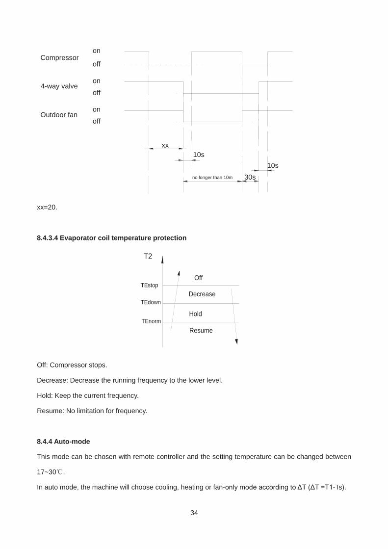
Defrosting action
34
Compressoron
off
on
on
off
off
4-way valve
Outdoor fan
xx
no longer than 10m 30s
10s10s
xx=20.
8.4.3.4 Evaporator coil temperature protection
TEstop
T2
Resume
Off
DecreaseTEdown
TEnormHold
Off: Compressor stops.
Decrease: Decrease the running frequency to the lower level.
Hold: Keep the current frequency.
Resume: No limitation for frequency.
8.4.4 Auto-mode
This mode can be chosen with remote controller and the setting temperature can be changed between
17~30 .
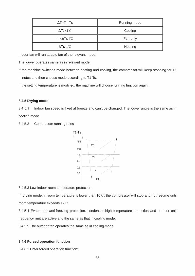
In auto mode, the machine will choose cooling, heating or fan-only mode according to ΔT (ΔT =T1-Ts).
35
ΔT=T1-Ts Running mode
ΔT 1 Cooling
-1<ΔT≤1 Fan-only
ΔT≤-1 Heating
Indoor fan will run at auto fan of the relevant mode.
The louver operates same as in relevant mode.
If the machine switches mode between heating and cooling, the compressor will keep stopping for 15
minutes and then choose mode according to T1-Ts.
If the setting temperature is modified, the machine will choose running function again.
8.4.5 Drying mode
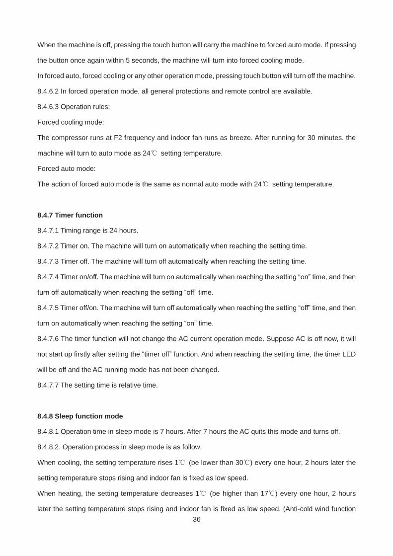
8.4.5.1 Indoor fan speed is fixed at breeze and can’t be changed. The louver angle is the same as in
cooling mode.
8.4.5.2 Compressor running rules
2.0
1.5
1.0
T1-Ts
F7
F5
F3
F1
2.5
0.5
0.0
8.4.5.3 Low indoor room temperature protection
In drying mode, if room temperature is lower than 10 , the compressor will stop and not resume until
room temperature exceeds 12 .
8.4.5.4 Evaporator anti-freezing protection, condenser high temperature protection and outdoor unit
frequency limit are active and the same as that in cooling mode.
8.4.5.5 The outdoor fan operates the same as in cooling mode.
8.4.6 Forced operation function
8.4.6.1 Enter forced operation function:
36
When the machine is off, pressing the touch button will carry the machine to forced auto mode. If pressing
the button once again within 5 seconds, the machine will turn into forced cooling mode.
In forced auto, forced cooling or any other operation mode, pressing touch button will turn off the machine.
8.4.6.2 In forced operation mode, all general protections and remote control are available.
8.4.6.3 Operation rules:
Forced cooling mode:
The compressor runs at F2 frequency and indoor fan runs as breeze. After running for 30 minutes. the
machine will turn to auto mode as 24 setting temperature.
Forced auto mode:
The action of forced auto mode is the same as normal auto mode with 24 setting temperature.
8.4.7 Timer function
8.4.7.1 Timing range is 24 hours.
8.4.7.2 Timer on. The machine will turn on automatically when reaching the setting time.
8.4.7.3 Timer off. The machine will turn off automatically when reaching the setting time.
8.4.7.4 Timer on/off. The machine will turn on automatically when reaching the setting “on” time, and then
turn off automatically when reaching the setting “off” time.
8.4.7.5 Timer off/on. The machine will turn off automatically when reaching the setting “off” time, and then
turn on automatically when reaching the setting “on” time.
8.4.7.6 The timer function will not change the AC current operation mode. Suppose AC is off now, it will
not start up firstly after setting the “timer off” function. And when reaching the setting time, the timer LED
will be off and the AC running mode has not been changed.
8.4.7.7 The setting time is relative time.
8.4.8 Sleep function mode
8.4.8.1 Operation time in sleep mode is 7 hours. After 7 hours the AC quits this mode and turns off.
8.4.8.2. Operation process in sleep mode is as follow:
When cooling, the setting temperature rises 1 (be lower than 30 ) every one hour, 2 hours later the
setting temperature stops rising and indoor fan is fixed as low speed.
When heating, the setting temperature decreases 1 (be higher than 17 ) every one hour, 2 hours
later the setting temperature stops rising and indoor fan is fixed as low speed. (Anti-cold wind function
37
has the priority)
8.4.8.3 Timer setting is available
8.4.8.4 When user uses timer off function in sleep mode (or sleep function in timer off mode), if the timing
is less than 7 hours, sleep function will be cancelled when reaching the setting time. If the timing is more
than 7 hours, the machine will not stop until reaches the setting time in sleep mode.
8.4.9 Auto-Restart function
The indoor unit is equipped with auto-restart function, which is carried out through an auto-restart module.
In case of a sudden power failure, the module memorizes the setting conditions before the power failure.
The unit will resume the previous operation setting (not including swing function) automatically after 3
minutes when power returns.
If the memorization condition is forced cooling mode, the unit will run in cooling mode for 30 minutes and
turn to auto mode as 24 setting temp.
If AC is off before power off and AC is required to start up now, the compressor will have 1 minute delay
when power on. Other conditions, the compressor will have 3 minutes delay when restarts.
8.4.10 8 Heating(optional)
In heating operation, the preset temperature of the air conditioner can be as lower as 8 , which keeps
the room temperature steady at 8 and prevents household things freezing when the house is
unoccupied for a long time in severe cold weather.
8.4.11 Follow me(optional)
1) If the indoor PCB receives the signal which results from pressing the FOLLOW ME button on
remote controller, the buzzer will emit a sound and this indicates the follow me function is initiated. But
when the indoor PCB receives signal which sent from remote controller every 3 minutes, the buzzer will
not respond. When the unit is running with follow me function, the PCB will control the unit according to
the temperature from follow me signal, and the temperature collection function of room temperature
sensor will be shielded, but the error detective function of room temperature sensor will be still valid.
2) When the follow me function is available, the PCB will control the unit according to the room
temperature from the remote controller and the setting temperature.
3) The PCB will take action to the mode change information from remote controller signal, but it
38
will not affected by the setting temperature.
4) When the unit is running with follow me function, if the PCB doesn’t receive any signal from
remote controller for 7 minutes or pressing FOLLOW ME button again, the follow me function will be
turned off automatically, and the temperature collection function of room temperature sensor will be
available, the PCB will control the unit according to the room temperature detected from its own room
temperature sensor and setting temperature.
8.4.12 Self clean(optional)
For heat pump models which are provided with this function, after running in cooling or drying mode, if
the user press “Self Clean” button on remote controller, firstly, indoor unit runs in fan only mode for a
while, then low heat operation and finally runs in fan only again. This function can keep the inside of
indoor unit dry and prevent breeding of mold.
8.4.13 Refrigerant Leakage Detection
With this new technology, the display area will show “EC” when the outdoor unit detects refrigerant
leakage.
8.4.14 Louver Position Memory Function
When starting the unit again after shutting down, its louver will restore to the angle originally set by the
user, but the precondition is that the angle must be within the allowable range, if it exceeds, it will
memorize the maximum angle of the louver. During operation, if the power fails or the end user shuts
down the unit in the turbo mode, the louver will restore to the default angle.
8.4.15 INTELLIGENT EYE(optional)
With the built-in infrared sensor, the indoor unit detects human movement. The AC will turn off if you leave
the room for 30 minutes and turn on automatically when you come back, which helps saving more energy.
8.4.16 Silence operation(optional)
Press the “silence” button on remote controller to initiate SILENCE function. When the Silence function
is activated, the compressor running frequency will keep lower than F2 and the indoor unit will bring faint
breeze, which will reduce the noise to the lowest level and create a quiet and comfortable room for you.
39
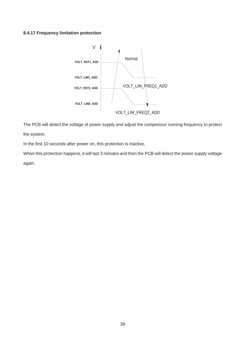
8.4.17 Frequency limitation protection
V
VOLT_RST1_ADDNormal
VOLT_LIM_FREQ1_ADD
VOLT_LIM1_ADD
VOLT_RST2_ADD
VOLT_LIM2_ADD
VOLT_LIM_FREQ2_ADD
The PCB will detect the voltage of power supply and adjust the compressor running frequency to protect
the system.
In the first 10 seconds after power on, this protection is inactive.
When this protection happens, it will last 3 minutes and then the PCB will detect the power supply voltage
again.
40
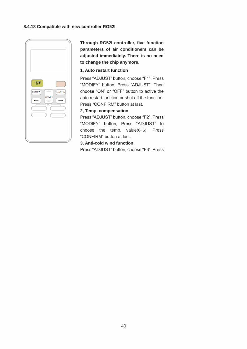
8.4.18 Compatible with new controller RG52I
Through RG52I controller, five function parameters of air conditioners can be adjusted immediately. There is no need to change the chip anymore.
1, Auto restart function
Press “ADJUST” button, choose “F1”. Press “MODIFY” button, Press “ADJUST” .Then choose “ON” or “OFF” button to active the auto restart function or shut off the function. Press “CONFIRM” button at last. 2, Temp. compensation. Press “ADJUST” button, choose “F2”. Press “MODIFY” button, Press “ADJUST” to choose the temp. value(0~6). Press “CONFIRM” button at last. 3, Anti-cold wind function Press “ADJUST” button, choose “F3”. Press
41
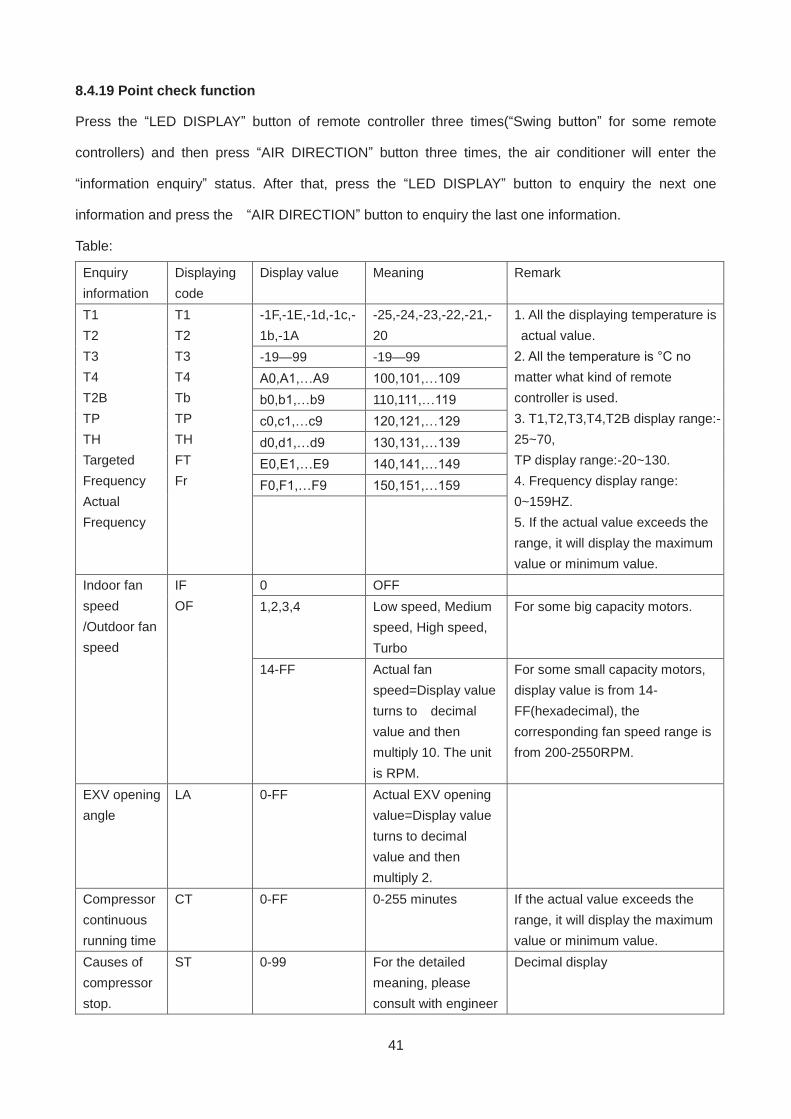
8.4.19 Point check function
Press the “LED DISPLAY” button of remote controller three times(“Swing button” for some remote
controllers) and then press “AIR DIRECTION” button three times, the air conditioner will enter the
“information enquiry” status. After that, press the “LED DISPLAY” button to enquiry the next one
information and press the “AIR DIRECTION” button to enquiry the last one information.
Table:
Enquiry information
Displaying code
Display value Meaning Remark
T1 T2 T3 T4 T2B TP TH Targeted Frequency Actual Frequency
T1 T2 T3 T4 Tb TP TH FT Fr
-1F,-1E,-1d,-1c,-1b,-1A
-25,-24,-23,-22,-21,-20
1. All the displaying temperature is actual value.
2. All the temperature is °C no matter what kind of remote controller is used. 3. T1,T2,T3,T4,T2B display range:-25~70, TP display range:-20~130. 4. Frequency display range: 0~159HZ. 5. If the actual value exceeds the range, it will display the maximum value or minimum value.
-19—99 -19—99 A0,A1,…A9 100,101,…109 b0,b1,…b9 110,111,…119 c0,c1,…c9 120,121,…129 d0,d1,…d9 130,131,…139 E0,E1,…E9 140,141,…149 F0,F1,…F9 150,151,…159
Indoor fan speed /Outdoor fan speed
IF OF
0 OFF 1,2,3,4 Low speed, Medium
speed, High speed, Turbo
For some big capacity motors.
14-FF Actual fan speed=Display value turns to decimal value and then multiply 10. The unit is RPM.
For some small capacity motors, display value is from 14-FF(hexadecimal), the corresponding fan speed range is from 200-2550RPM.
EXV opening angle
LA 0-FF Actual EXV opening value=Display value turns to decimal value and then multiply 2.
Compressor continuous running time
CT 0-FF 0-255 minutes If the actual value exceeds the range, it will display the maximum value or minimum value.
Causes of compressor stop.
ST 0-99 For the detailed meaning, please consult with engineer
Decimal display
42
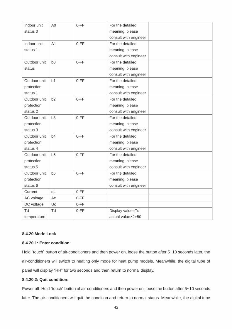
Indoor unit status 0
A0 0-FF For the detailed meaning, please consult with engineer
Indoor unit status 1
A1 0-FF For the detailed meaning, please consult with engineer
Outdoor unit status
b0 0-FF For the detailed meaning, please consult with engineer
Outdoor unit protection status 1
b1 0-FF For the detailed meaning, please consult with engineer
Outdoor unit protection status 2
b2 0-FF For the detailed meaning, please consult with engineer
Outdoor unit protection status 3
b3 0-FF For the detailed meaning, please consult with engineer
Outdoor unit protection status 4
b4 0-FF For the detailed meaning, please consult with engineer
Outdoor unit protection status 5
b5 0-FF For the detailed meaning, please consult with engineer
Outdoor unit protection status 6
b6 0-FF For the detailed meaning, please consult with engineer
Current dL 0-FF AC voltage Ac 0-FF DC voltage Uo 0-FF Td temperature
Td 0-FF Display value=Td actual value×2+50
8.4.20 Mode Lock
8.4.20.1: Enter condition:
Hold “touch” button of air-conditioners and then power on, loose the button after 5~10 seconds later, the
air-conditioners will switch to heating only mode for heat pump models. Meanwhile, the digital tube of
panel will display “HH” for two seconds and then return to normal display.
8.4.20.2: Quit condition:
Power off. Hold “touch” button of air-conditioners and then power on, loose the button after 5~10 seconds
later. The air-conditioners will quit the condition and return to normal status. Meanwhile, the digital tube
43
of panel will display “CH” for two seconds and then return to normal display.
44
9. Troubleshooting
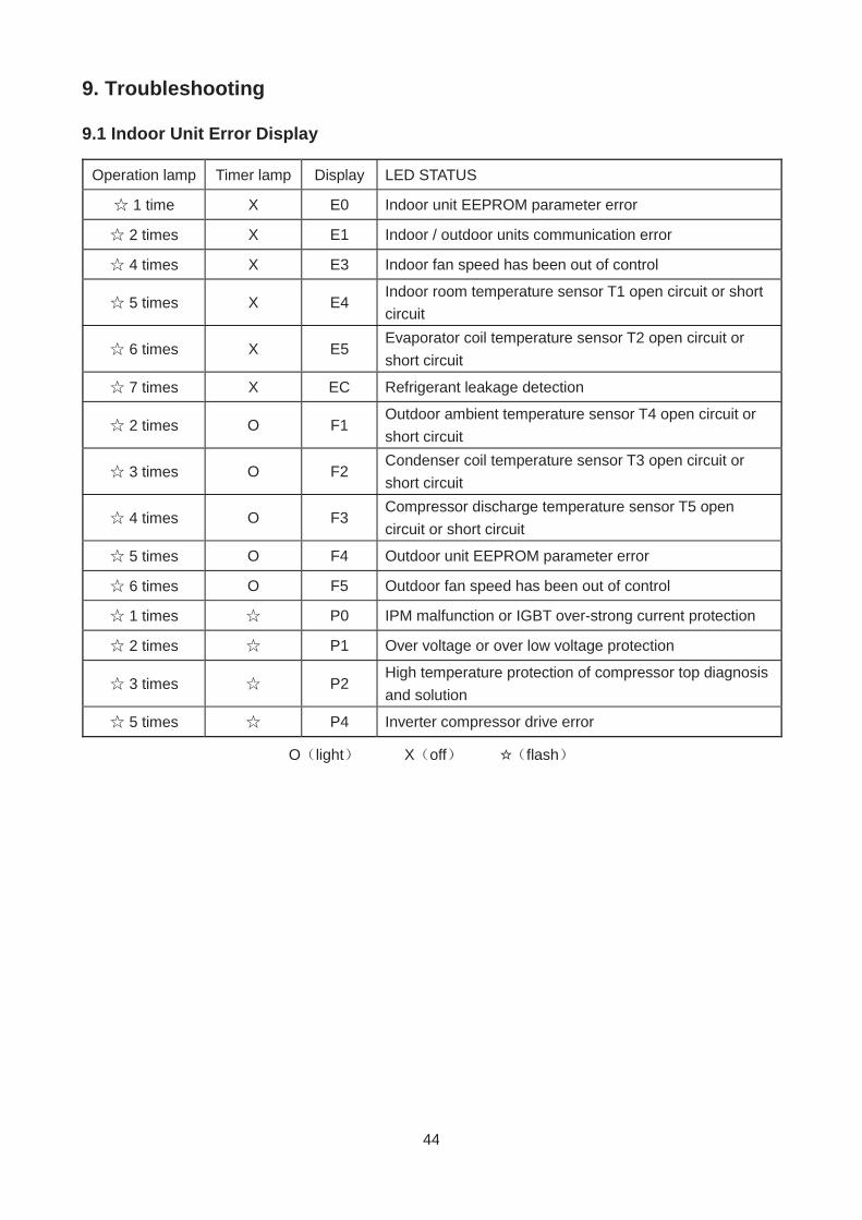
9.1 Indoor Unit Error Display
Operation lamp Timer lamp Display LED STATUS
1 time X E0 Indoor unit EEPROM parameter error
2 times X E1 Indoor / outdoor units communication error
4 times X E3 Indoor fan speed has been out of control
5 times X E4 Indoor room temperature sensor T1 open circuit or short circuit
6 times X E5 Evaporator coil temperature sensor T2 open circuit or short circuit
7 times X EC Refrigerant leakage detection
2 times O F1 Outdoor ambient temperature sensor T4 open circuit or short circuit
3 times O F2 Condenser coil temperature sensor T3 open circuit or short circuit
4 times O F3 Compressor discharge temperature sensor T5 open circuit or short circuit
5 times O F4 Outdoor unit EEPROM parameter error
6 times O F5 Outdoor fan speed has been out of control
1 times P0 IPM malfunction or IGBT over-strong current protection
2 times P1 Over voltage or over low voltage protection
3 times P2 High temperature protection of compressor top diagnosis and solution
5 times P4 Inverter compressor drive error
O light X off flash
45
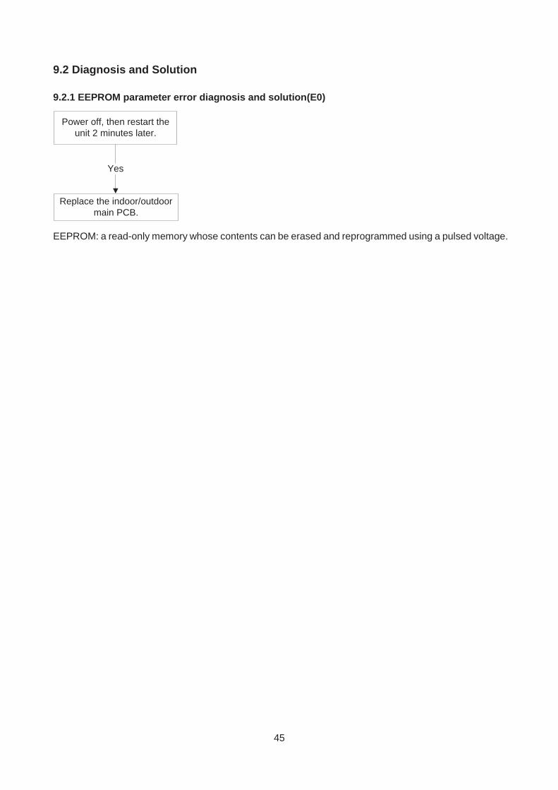
9.2 Diagnosis and Solution
9.2.1 EEPROM parameter error diagnosis and solution(E0)
Yes
Replace the indoor/outdoormain PCB.
Power off, then restart theunit 2 minutes later.
EEPROM: a read-only memory whose contents can be erased and reprogrammed using a pulsed voltage.
46
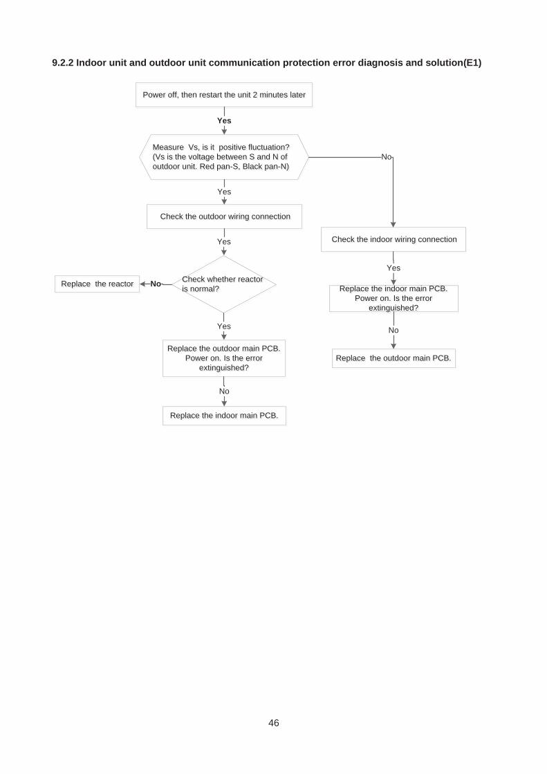
9.2.2 Indoor unit and outdoor unit communication protection error diagnosis and solution(E1)
easure Vs, is it positive fluctuation?(Vs is the voltage between S and N ofoutdoor unit. Red pan-S, Black pan-N)
Measure Vs, is it positive fluctuation?(Vs is the voltage between S and N ofoutdoor unit. Red pan-S, Black pan-N)
Yes
ower offff , then restart the unit 2 minutes laterPower off, then restart the unit 2 minutes later
No
Replace the outdoor main PCB.Power on. Is the error
extinguished?
Replace the outdoor main PCB.Power on. Is the error
extinguished?
Check the outdoor wiring connectionCheck the outdoor wiring connection
Replace the indoor main PCB.Power on. Is the error
extinguished?g
Replace the indoor main PCB.Power on. Is the error
extinguished?
Yes
Replace the outdoor main PCB.Replace the outdoor main PCB.
No
Replace the indoor main PCB.Replace the indoor main PCB.
No
Check the indoor wiring connectionCheck the indoor wiring connectionYes
Yes
Check whether reactoris normal?CisCheck whether reactoris normal?
Yes
Replace the reactorReplace the reactor No
47
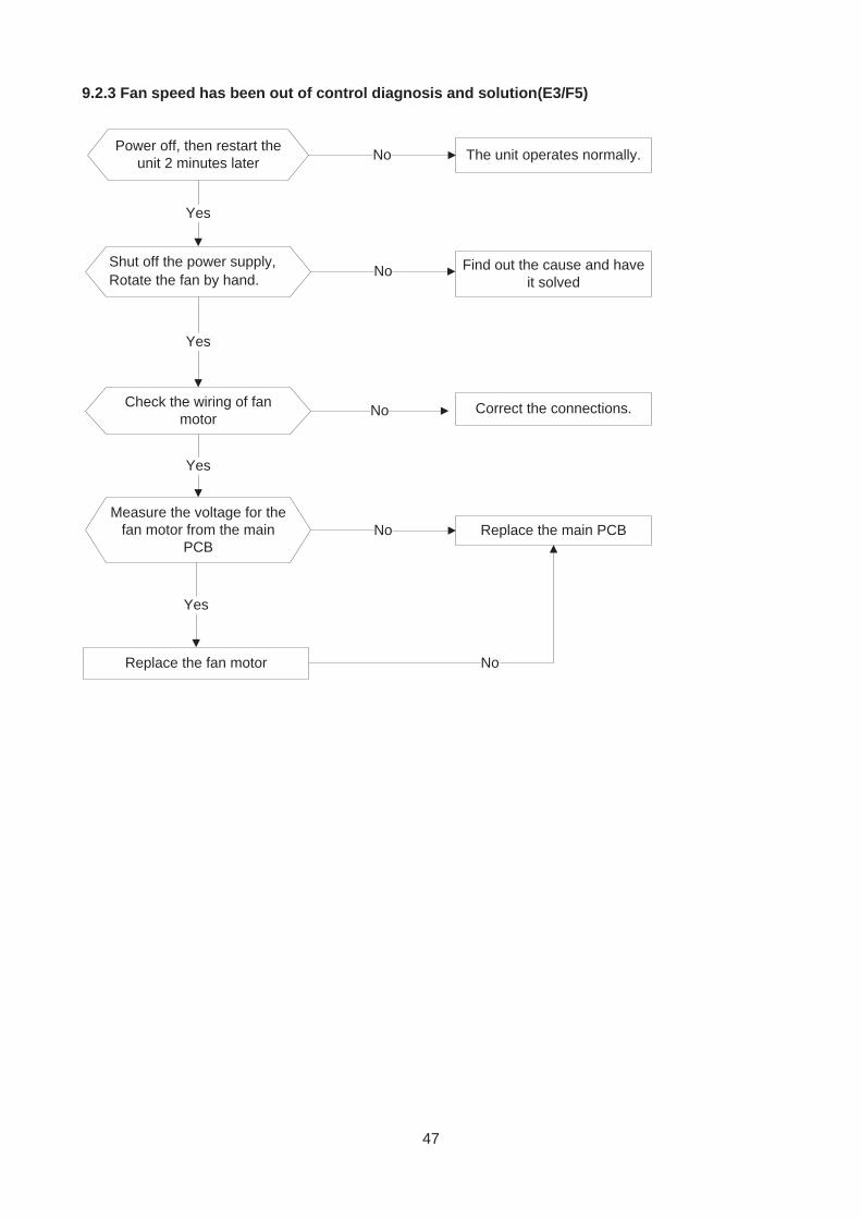
9.2.3 Fan speed has been out of control diagnosis and solution(E3/F5)
Power off, then restart theunit 2 minutes later
Shut off the power supply,Rotate the fan by hand.
The unit operates normally.
Find out the cause and haveit solved
Check the wiring of fanmotor
No
Yes
No
Correct the connections.No
NoReplace the fan motor
Yes
Yes
Measure the voltage for thefan motor from the main
PCB
Yes
Replace the main PCBNo
48
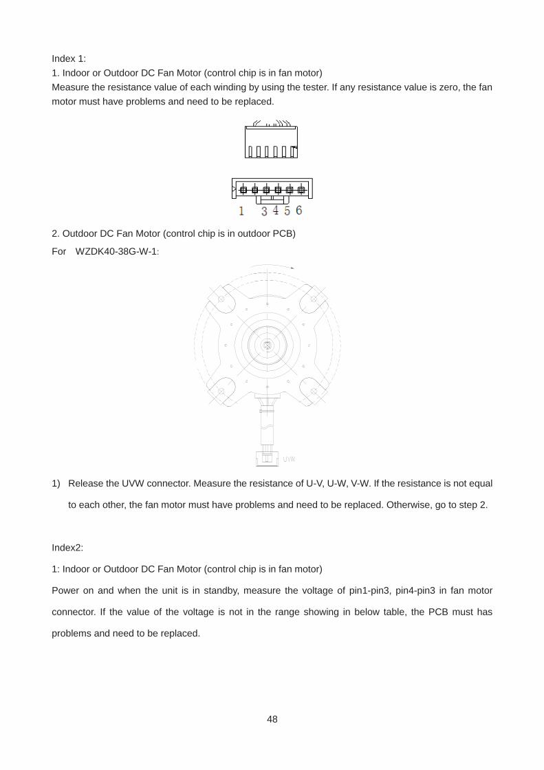
Index 1: 1. Indoor or Outdoor DC Fan Motor (control chip is in fan motor) Measure the resistance value of each winding by using the tester. If any resistance value is zero, the fan motor must have problems and need to be replaced.
2. Outdoor DC Fan Motor (control chip is in outdoor PCB)
For WZDK40-38G-W-1:
1) Release the UVW connector. Measure the resistance of U-V, U-W, V-W. If the resistance is not equal
to each other, the fan motor must have problems and need to be replaced. Otherwise, go to step 2.
Index2:
1: Indoor or Outdoor DC Fan Motor (control chip is in fan motor)
Power on and when the unit is in standby, measure the voltage of pin1-pin3, pin4-pin3 in fan motor
connector. If the value of the voltage is not in the range showing in below table, the PCB must has
problems and need to be replaced.
49
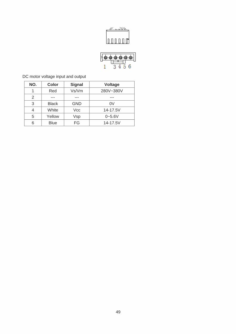
DC motor voltage input and output
NO. Color Signal Voltage 1 Red Vs/Vm 280V~380V 2 --- --- --- 3 Black GND 0V 4 White Vcc 14-17.5V 5 Yellow Vsp 0~5.6V 6 Blue FG 14-17.5V
50
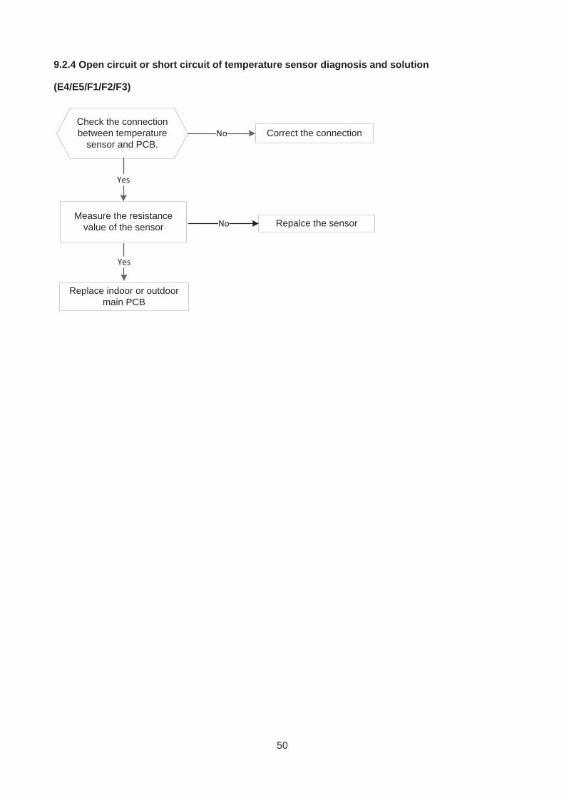
9.2.4 Open circuit or short circuit of temperature sensor diagnosis and solution
(E4/E5/F1/F2/F3)
Check the connectionbetween temperature
sensor and PCB.Correct the connectionNo
Yes
Replace indoor or outdoormain PCB
Measure the resistancevalue of the sensor Repalce the sensorNo
Yes
51
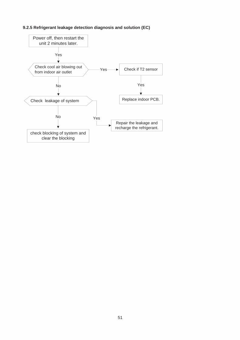
9.2.5 Refrigerant leakage detection diagnosis and solution (EC)
Check cool air blowing outfrom indoor air outlet
Yes
Yes Check if T2 sensor
No
Check leakage of system
No
Power off, then restart theunit 2 minutes later.
Replace indoor PCB.
Yes
Repair the leakage andrecharge the refrigerant.
Yes
check blockIng of system andclear the blocking
52
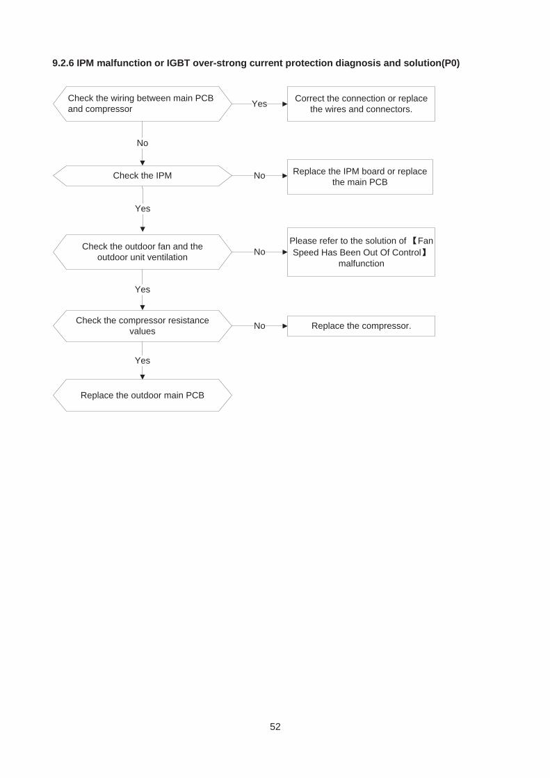
9.2.6 IPM malfunction or IGBT over-strong current protection diagnosis and solution(P0)
Check the wiring between main PCBand compressor
Correct the connection or replacethe wires and connectors.Yes
No
Check the IPM No
Yes
Replace the IPM board or replacethe main PCB
Check the outdoor fan and theoutdoor unit ventilation No
Please refer to the solution of FanSpeed Has Been Out Of Control
malfunction
Yes
Check the compressor resistancevalues No Replace the compressor.
Yes
Replace the outdoor main PCB
53
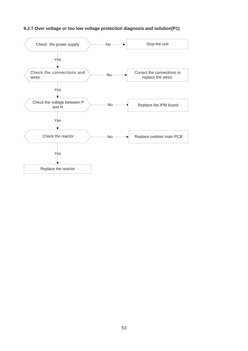
9.2.7 Over voltage or too low voltage protection diagnosis and solution(P1)
Check the power supply
Check the connections andwires
Stop the unitNo
Yes
No Correct the connections orreplace the wires.
Yes
Replace the reactor
Yes
No Replace the IPM boardCheck the voltage between P
and N
Check the reactor
Yes
No Replace outdoor main PCB
54
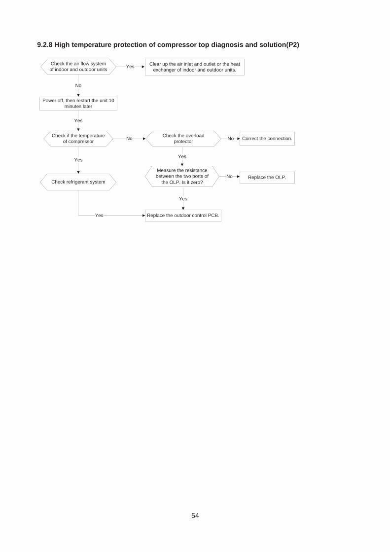
9.2.8 High temperature protection of compressor top diagnosis and solution(P2)
Check the air flow systemof indoor and outdoor units
Clear up the air inlet and outlet or the heatexchanger of indoor and outdoor units.
Yes
No
Yes
Yes
Power off, then restart the unit 10minutes later
Check if the temperatureof compressor No
Check refrigerant system
Yes
Check the overloadprotector Correct the connection.No
Measure the resistancebetween the two ports of
the OLP. Is it zero?
Yes
Replace the OLP.No
Replace the outdoor control PCB.
Yes
55
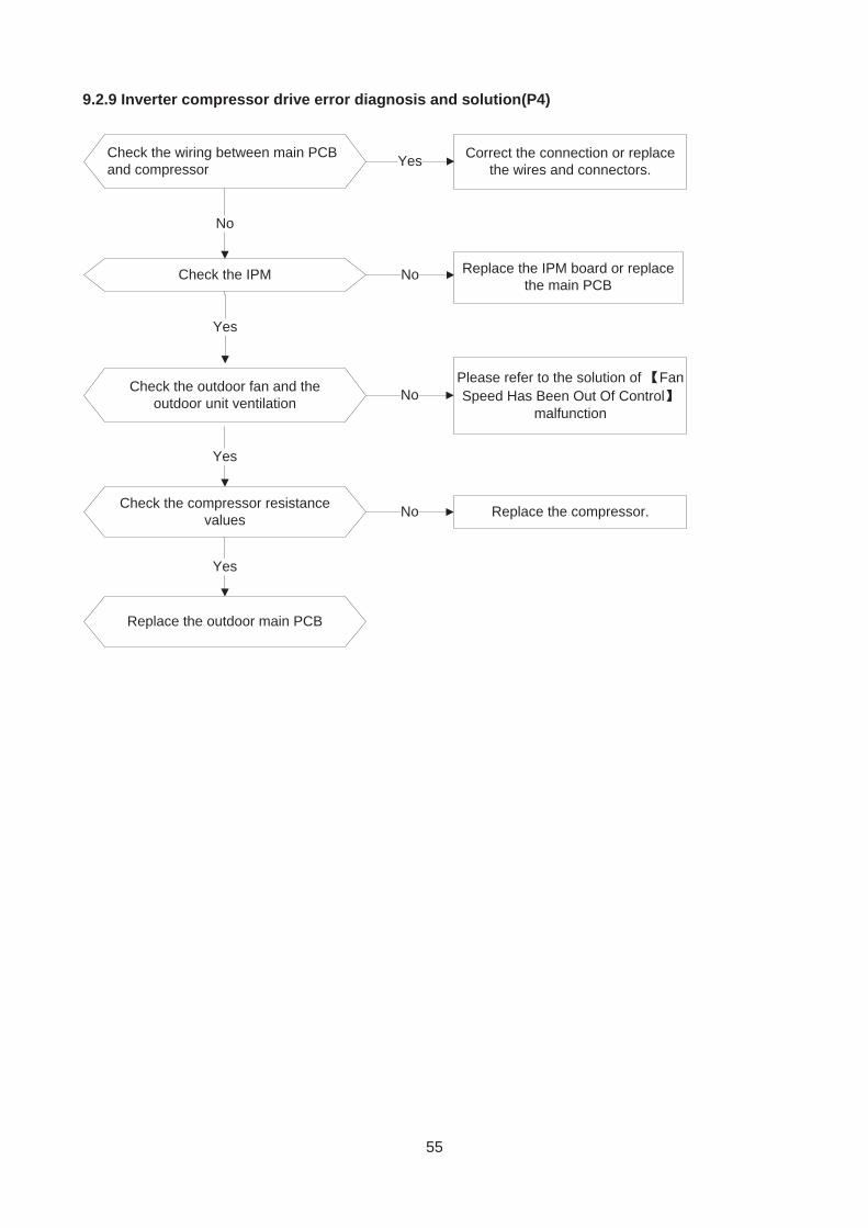
9.2.9 Inverter compressor drive error diagnosis and solution(P4)
Check the wiring between main PCBand compressor
Correct the connection or replacethe wires and connectors.Yes
No
Check the IPM No
Yes
Replace the IPM board or replacethe main PCB
Check the outdoor fan and theoutdoor unit ventilation No
Please refer to the solution of FanSpeed Has Been Out Of Control
malfunction
Yes
Check the compressor resistancevalues No Replace the compressor.
Yes
Replace the outdoor main PCB
56
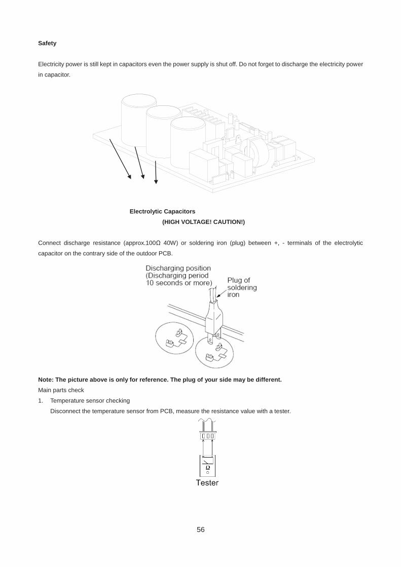
Safety
Electricity power is still kept in capacitors even the power supply is shut off. Do not forget to discharge the electricity power
in capacitor.
Electrolytic Capacitors
(HIGH VOLTAGE! CAUTION!)
Connect discharge resistance (approx.100Ω 40W) or soldering iron (plug) between +, - terminals of the electrolytic
capacitor on the contrary side of the outdoor PCB.
Note: The picture above is only for reference. The plug of your side may be different. Main parts check
1. Temperature sensor checking
Disconnect the temperature sensor from PCB, measure the resistance value with a tester.
57
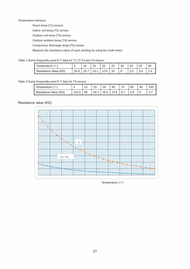
Temperature Sensors.
Room temp.(T1) sensor,
Indoor coil temp.(T2) sensor,
Outdoor coil temp.(T3) sensor,
Outdoor ambient temp.(T4) sensor,
Compressor discharge temp.(T5) sensor.
Measure the resistance value of each winding by using the multi-meter.
Table 1:Some frequently-used R-T data for T1,T2,T3 and T4 sensor:
Temperature ( ) 5 10 15 20 25 30 40 50 60
Resistance Value (KΩ) 26.9 20.7 16.1 12.6 10 8 5.2 3.5 2.4
Table 2:Some frequently-used R-T data for T5 sensor:
Temperature ( ) 5 15 25 35 60 70 80 90 100
Resistance Value (KΩ) 141.6 88 56.1 36.6 13.8 9.7 6.9 5 3.7
Resistance value (KΩ)
Temperature ( )
T
T1 T2
58
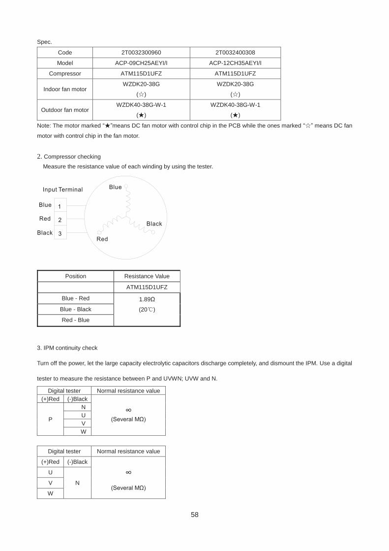
Spec.
Code 2T0032300960 2T0032400308
Model ACP-09CH25AEYI/I ACP-12CH35AEYI/I
Compressor ATM115D1UFZ ATM115D1UFZ
Indoor fan motor WZDK20-38G
( )
WZDK20-38G
( )
Outdoor fan motor WZDK40-38G-W-1
( )
WZDK40-38G-W-1
( )
Note: The motor marked “ ”means DC fan motor with control chip in the PCB while the ones marked “ ” means DC fan
motor with control chip in the fan motor.
2. Compressor checking
Measure the resistance value of each winding by using the tester.
3. IPM continuity check
Turn off the power, let the large capacity electrolytic capacitors discharge completely, and dismount the IPM. Use a digital
tester to measure the resistance between P and UVWN; UVW and N.
Digital tester Normal resistance value (+)Red (-)Black
∞ (Several MΩ) P
N U V W
Digital tester Normal resistance value
(+)Red (-)Black
∞ (Several MΩ)
U
N V
W
Position Resistance Value
ATM115D1UFZ
Blue - Red 1.89Ω
(20 )
Blue - Black
Red - Blue