Embed Size (px)
Citation preview
Acoustic Techniques for Gas-Lift Wells
“Acoustic Techniques to Monitor and Troubleshoot Gas-lift Wells”, Taylor, Rowlan, McCoy SPE-169536-MS
“Dual Shot Acoustic Technique”, Province, Taylor, Rowlan, McCoy, SWPSC 2018
Presenter: Carrie-Anne TaylorQ & A: with Lynn Rowlan and Gustavo Fernandez
Ask Echometer Online Session – June 17, 2020
Ask Echometer Session 5:• Benefits of Fluid Levels on gas-lift wells.• Introduction to Dual Shot Acoustic Technique• Gas-lift well file set up in TAM• Analyzing gas-lift fluid levels shots and tips for
analyzing difficult shots with multiple reflection kicks
2
Benefits of Fluid Levels on Gas-Lift Wells
The distance to the fluid level provides beneficial information throughout the life of a gas-lift well. • Fluid level depth with respect to the valve• Depth to the deepest mandrel uncovered• Verify Unloading process is proceeding properly• Find holes, restrictions• Wellbore problem or equipment malfunction?• How can acoustics aid in Troubleshooting?
3

Fluid Levels During Unloading Sequence
4
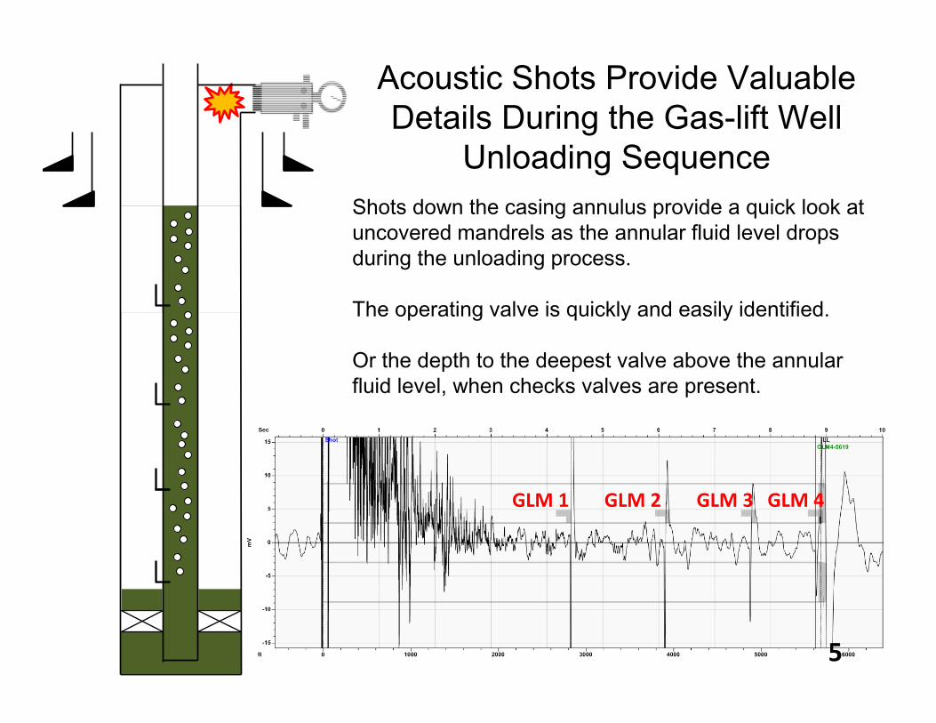
Shots down the casing annulus provide a quick look at uncovered mandrels as the annular fluid level drops during the unloading process.
The operating valve is quickly and easily identified.
Or the depth to the deepest valve above the annular fluid level, when checks valves are present.
Acoustic Shots Provide Valuable Details During the Gas-lift Well
Unloading Sequence
GLM 1 GLM 2 GLM 3 GLM 4
5

Fluid Levels on a Stabilized Gas Lift System
6
Monitoring Fluid Levels on Gas-lift
• Annular fluid levels should remain constant with respect to the operating valve.
• Oscillations of the liquid level depth may indicate valve operation or gas injection rate problems.
• In a well with a packer, the deepest liquid level indicates the deepest mandrel uncovered from the unloading process.
• Wellbore integrity problems can be detected – Valves stuck open, Leaking packer, leaking check valves
• During workovers – stability of kill fluid depth
7
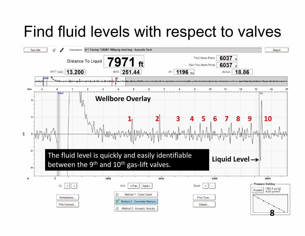
Find fluid levels with respect to valves
**BP Homa A‐1 Casing 12‐05‐07 IMP (08:04:01)
1 2 3 4 5 6 7 8 9 10
The fluid level is quickly and easily identifiable between the 9th and 10th gas‐lift valves.
Wellbore Overlay
Liquid Level
8
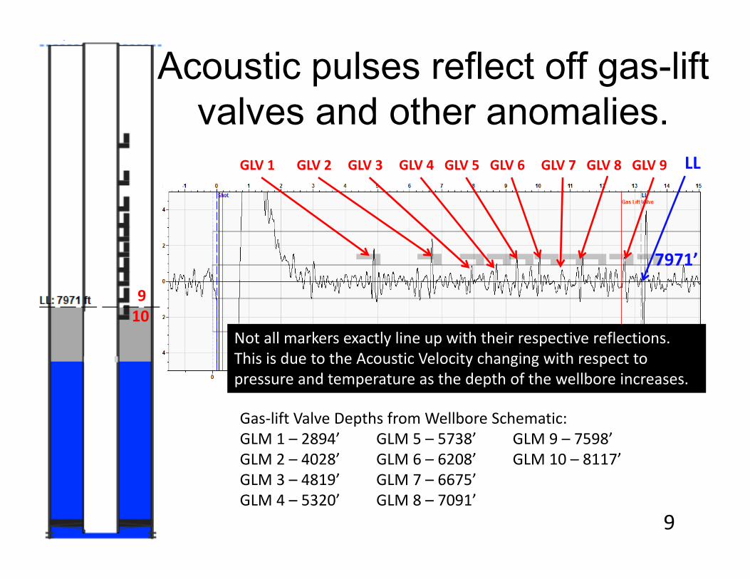
Gas‐lift Valve Depths from Wellbore Schematic:GLM 1 – 2894’ GLM 5 – 5738’ GLM 9 – 7598’GLM 2 – 4028’ GLM 6 – 6208’ GLM 10 – 8117’GLM 3 – 4819’ GLM 7 – 6675’GLM 4 – 5320’ GLM 8 – 7091’
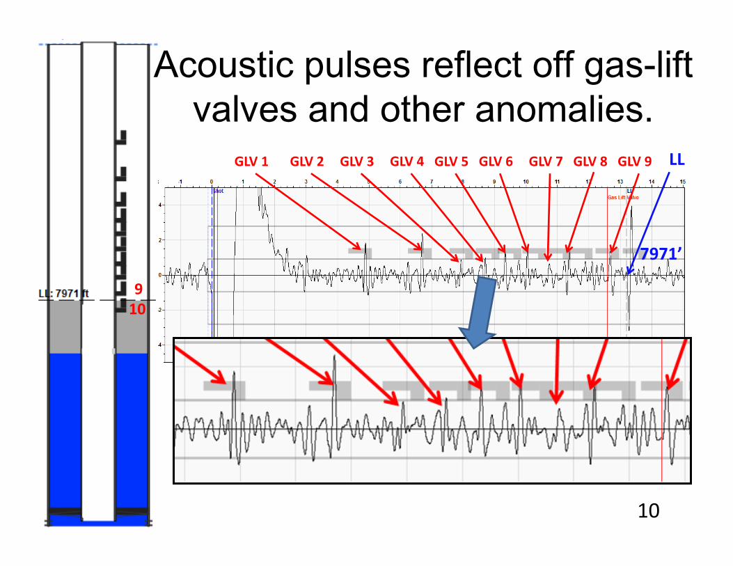
GLV 1 GLV 2 GLV 9GLV 5 GLV 6 GLV 8 LLGLV 3 GLV 4 GLV 7
Not all markers exactly line up with their respective reflections. This is due to the Acoustic Velocity changing with respect to pressure and temperature as the depth of the wellbore increases.
910
7971’
Acoustic pulses reflect off gas-lift valves and other anomalies.
9
GLV 1 GLV 2 GLV 9GLV 5 GLV 6 GLV 8 LLGLV 3 GLV 4 GLV 7
910
7971’
Acoustic pulses reflect off gas-lift valves and other anomalies.
10
Acoustic Velocity between Downhole Markers
11
Gas-lift Mandrels are Excellent Downhole Markers
• Purpose – Accurately calculate the distance to the liquid level plus other downhole reflectors such as gas-lift valves and mandrels, tubing collars, subsurface safety valves and possible holes or other problems.
• Distances – Determined using echoes from gas-lift valves at known distances from the wellhead.
• Accounts for – Variations of acoustic velocity commonly observed in most wellbores due to variations of temperature, pressure and gas composition as a function of depth.
12
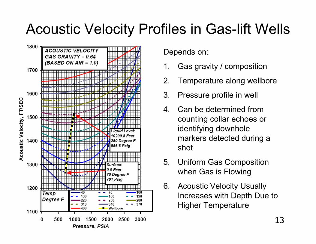
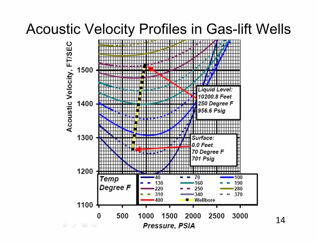
Acoustic Velocity Profiles in Gas-lift WellsDepends on:
1. Gas gravity / composition
2. Temperature along wellbore
3. Pressure profile in well
4. Can be determined from counting collar echoes or identifying downhole markers detected during a shot
5. Uniform Gas Composition when Gas is Flowing
6. Acoustic Velocity Usually Increases with Depth Due to Higher Temperature
13
Acoustic Velocity Profiles in Gas-lift Wells
14

Acoustic Velocity Affects Accuracy
Which marker should you choose?
15
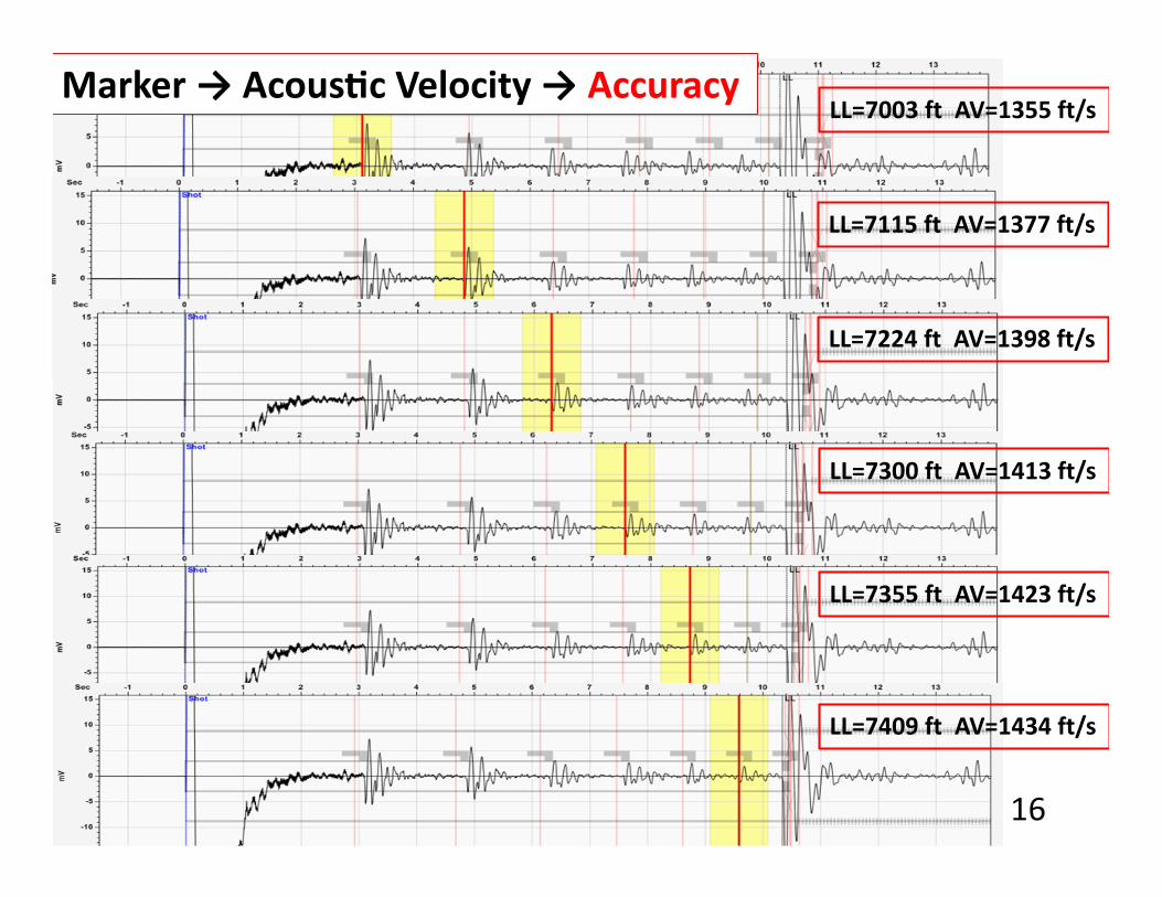
LL=7003 ft AV=1355 ft/s
LL=7115 ft AV=1377 ft/s
LL=7224 ft AV=1398 ft/s
LL=7300 ft AV=1413 ft/s
LL=7355 ft AV=1423 ft/s
LL=7409 ft AV=1434 ft/s
Marker → Acous c Velocity → Accuracy
16
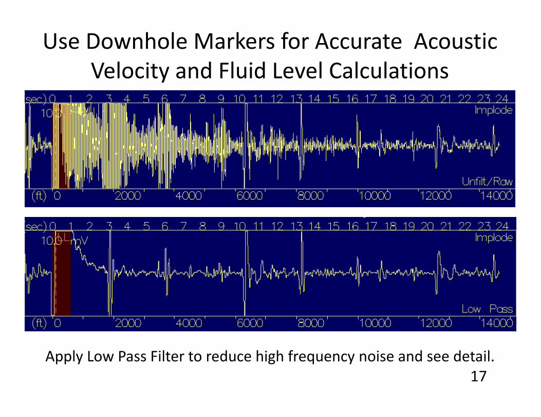
Use Downhole Markers for Accurate Acoustic Velocity and Fluid Level Calculations
Apply Low Pass Filter to reduce high frequency noise and see detail.17
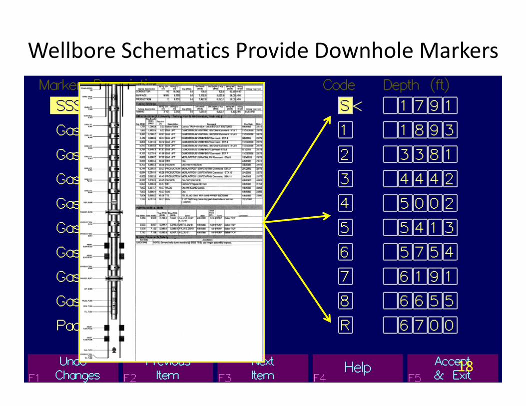
Wellbore Schematics Provide Downhole Markers
18

Acoustic Velocity is calculated between markers along the acoustic trace.
19

Awareness of the calculated Acoustic Velocity is important:• Quality check for correct
marker selection.• Verify gas-lift valves are
spaced correctly• Accurate fluid level
calculations.• Verify gas gravity and uniform
gas composition in the well. • Acoustic Velocity typically
displays an increasing trend in producing gas-lift wells.
If the Acoustic Velocity is out of “Range,” THERE IS A PROBLEM.
20
Direction of Kick Across Mandrels
21

Shape and Direction of Echoes from Valves and Mandrels
Photo: courtesy of Lufkin Industries
Two factors determine the direction of kick of gas-lift Mandrels on the acoustic trace:1) Physical characteristics of the mandrels2) Is the operator shooting down the tubing or the
casing?
22

Conventional vs. Side Pocket Mandrel Profiles
Picture courtesy of Jim Lea 23
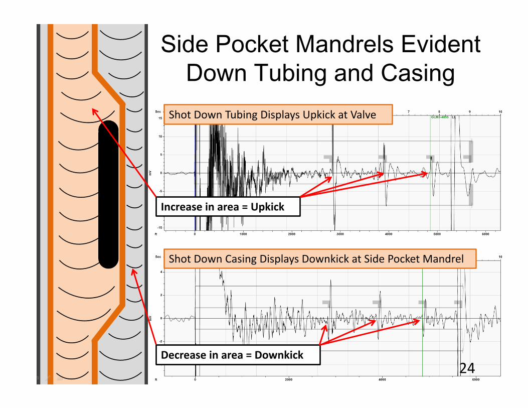
Side Pocket Mandrels Evident Down Tubing and Casing
Shot Down Tubing Displays Upkick at Valve
Shot Down Casing Displays Downkick at Side Pocket Mandrel
Increase in area = Upkick
Decrease in area = Downkick24
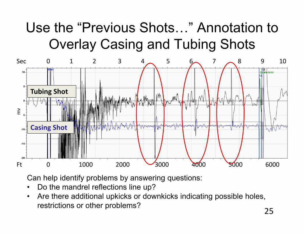
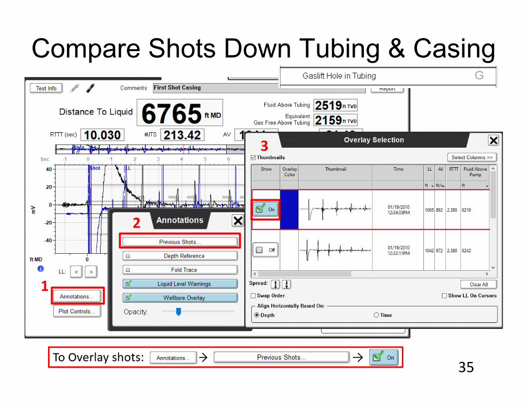
Use the “Previous Shots…” Annotation to Overlay Casing and Tubing Shots
Casing Shot
Tubing Shot
Can help identify problems by answering questions:• Do the mandrel reflections line up?• Are there additional upkicks or downkicks indicating possible holes,
restrictions or other problems?
Sec
Ft
mv
0 1 2 3 4 5 6 7 8 9 10
0 1000 2000 3000 4000 5000 6000
25
Horizontal Gas Lifted/Plunger Lifted Well
26

Stratified Gas Flow Regimes Exist in Horizontal Gas Wells
1. Fluid level shot down the tubing/casing annulus shows a liquid level at a MD of 9287 ft.
2. The ability to see past the end of the tubing is unusual in a vertical plunger lift well, because the liquid level is normally at the end of the tubing.
3. In horizontal wells, stratified flow exists; it is not uncommon to see features in the wellbore in the horizontal section past the end of the tubing.
4. Horizontal section appears to be relatively dry (no liquid level); but a significant amount of liquid enters the tubing.
5. Differential tubing and casing pressure do not indicate much liquid loading, but liquid exists in the horizontal and causes more liquid loading than expected (based on tubing and casing psi).
27
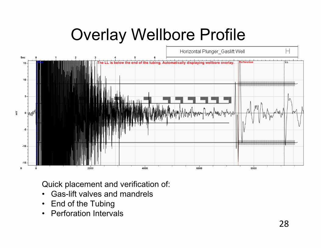
Quick placement and verification of:• Gas-lift valves and mandrels• End of the Tubing• Perforation Intervals
Overlay Wellbore Profile
28

Horizontal Plunger Lifted Well
GLV 1 @ 1712'GLV 2 @ 3014'GLV 3 @ 4092'GLV 4 @ 4797'GLV 5 @ 5256'GLV 6 @ 5716'GLV 7 @ 6176'GLV 8 @ 6570'GLV 9 @ 7031‘
Gas-lift Valves can be used to confirm the end of the tubing and the top of the perforations.
The fluid level is at a measured depth of 9118ft.
29
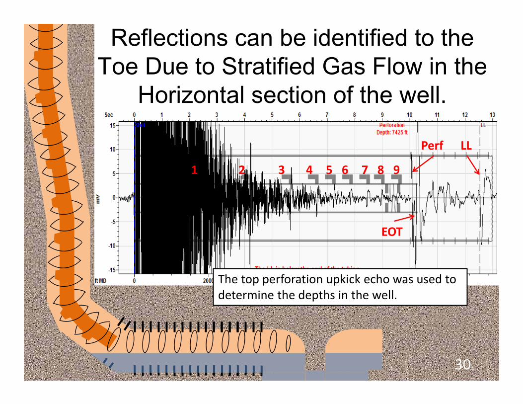
Reflections can be identified to the Toe Due to Stratified Gas Flow in the
Horizontal section of the well.
1 2 3 4 5 6 7 8 9
EOT
Perf LL
The top perforation upkick echo was used to determine the depths in the well.
30
Problems in the Tubing String
31
Identifying Holes in Tubing in a Gas-Lift Well
• In general, if lower valves are open OR the orifice is open and fluids can move into the casing annulus without a check valve stopping flow back into the annulus, then the liquid level will raise to maintain equilibrium with the gas pressure in the annulus.
• In this case, the liquid level will rise to the level of the deepest active injection point.
• If liquid flow back into the annulus is checked, then the liquid level will be below the deepest injection point previously obtained.
• If there is a hole in the tubing, then the liquid level in the annulus will rise to the hole in the tubing.
32
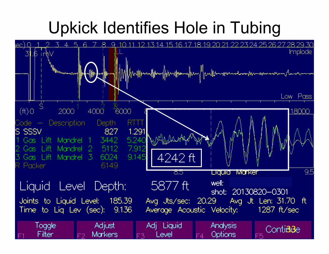
Upkick Identifies Hole in Tubing
Fluid Level
33
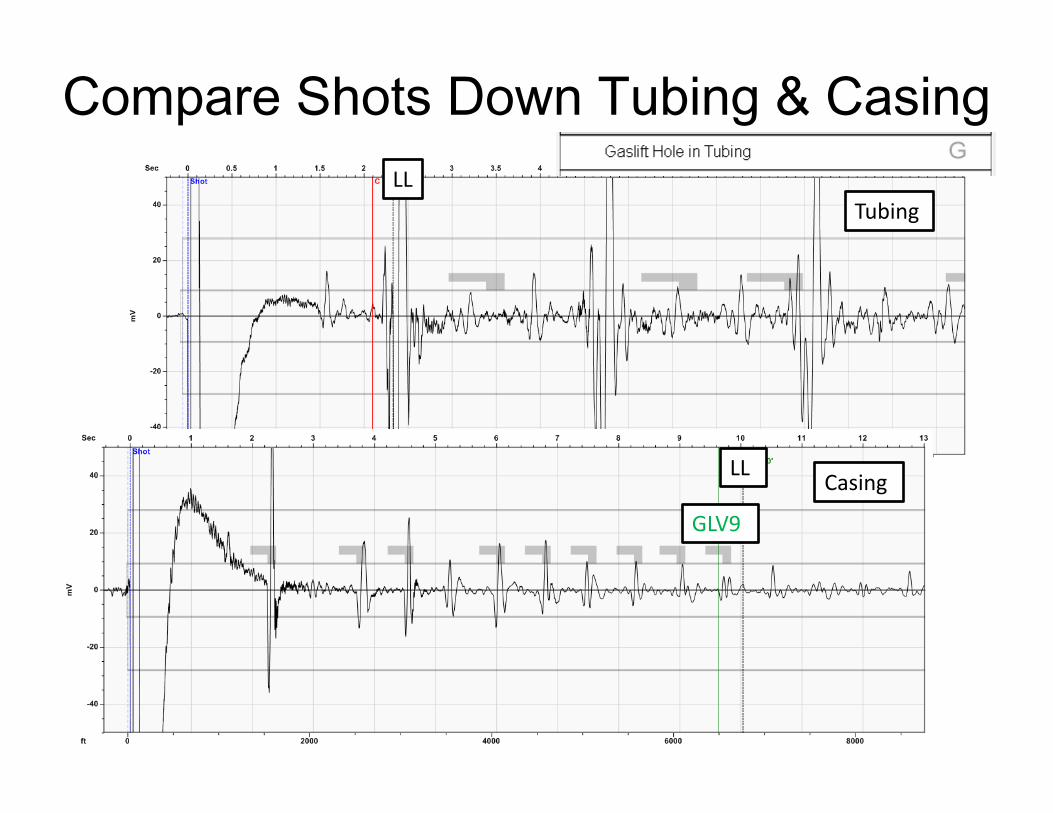
Compare Shots Down Tubing & Casing
Tubing
Casing
LL
LL
GLV9
35
Compare Shots Down Tubing & Casing
1
2
3
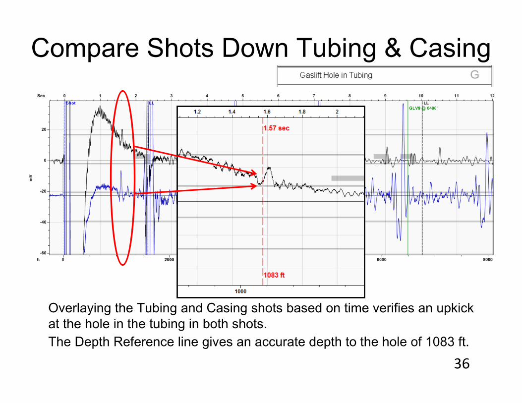
Compare Shots Down Tubing & Casing
Overlaying the Tubing and Casing shots based on time verifies an upkickat the hole in the tubing in both shots. The Depth Reference line gives an accurate depth to the hole of 1083 ft.
36
Tips and Techniques for Troubleshooting
37
QUESTION: DO I HAVE TO TURN GAS-LIFT INJECTION OFF BEFORE I SHOOT A FLUID LEVEL?
ANSWER: NO. UNLESS EXCESSIVE NOISE PROHIBITS ACCURATE FLUID LEVEL ANALYSIS.
Example: Off Shore Gas Lift Noisy Well
38
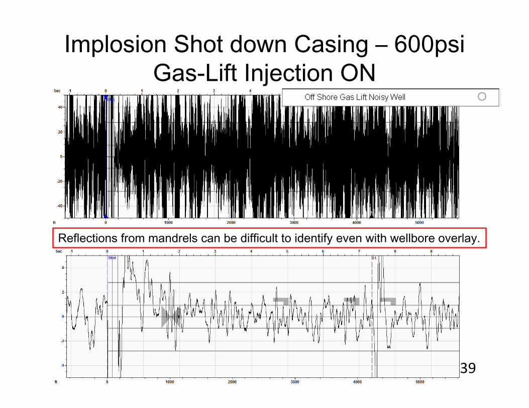
Implosion Shot down Casing – 600psiGas-Lift Injection ON
Reflections from mandrels can be difficult to identify even with wellbore overlay.
39

Implosion Shot down Casing – 600psiGas-Lift Injection OFF
Reflections from mandrels are clearly identifiable.
Other sources of background noise in gas-lift installations include compressors, reciprocating pumps, and wave-induced vibrations in offshore platforms.
40
QUESTION: HOW CAN I TELL A QUALITY FLUID LEVEL SHOT HAS BEEN ACQUIRED?
ANSWER: TAKE A SECOND SHOT FOR COMPARISON. ALWAYS.
If the shot doesn’t make sense, changes conditions and keep taking shots until you understand.
41
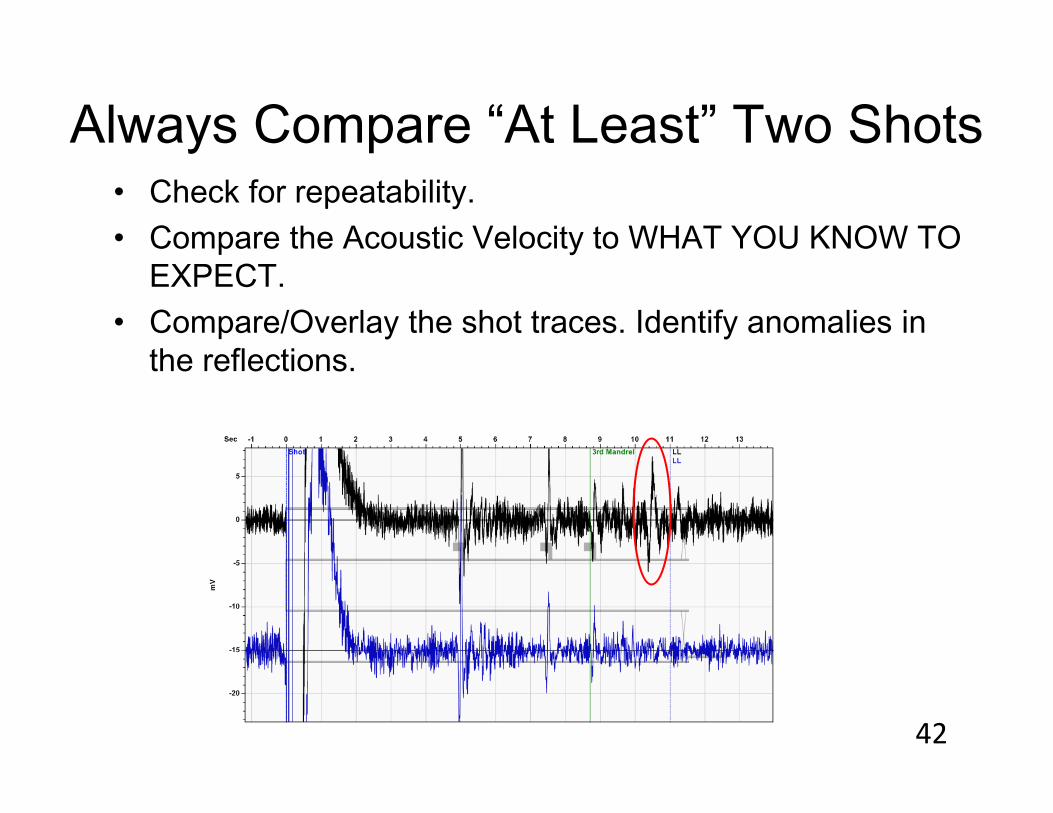
Always Compare “At Least” Two Shots• Check for repeatability.• Compare the Acoustic Velocity to WHAT YOU KNOW TO
EXPECT.• Compare/Overlay the shot traces. Identify anomalies in
the reflections.
42
QUESTION: What are some troubleshooting techniques used in the industry to check integrity?
ANSWER:The following example illustrates the use of a complete fluid level analysis to validate the gas lift design and verify the artificial lift system is operating efficiently.
43
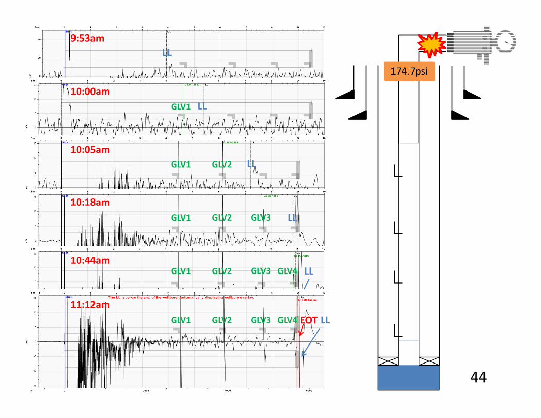
9:53am
10:00am
10:05am
10:18am
10:44am
89.8psi144.8psi155psi162.8psi169psi174.7psi
LL
LLGLV1
GLV1
GLV1
GLV1
LL
LL
LL
GLV2
GLV2
GLV2
GLV3
GLV3 GLV4
11:12amGLV1 LLGLV2 GLV3 GLV4 EOT
44

Fluid Levels fluctuate with an increase or decrease in tubing pressure.
2500
3000
3500
4000
4500
5000
5500
60000 20 40 60 80 100 120 140
180
120
150
90
2500
6000
4500
3500
5000
1400 80 1201006020 40
5500
4000
3000
Fluid Level Depth Tubing Pressure
60
Time, minutes 45
QUESTION: CAN A LEAKY GAS-LIFT VALVE BE DETECTED WITH AN ACOUSTIC SHOT?
ANSWER: YES, USING CERTAIN TECHNIQUES.
46
1 - Problem Gas-Lift Valve Identified Using Valve Reflection Study
• In a very high rate, high pressure gas-lift well, there was a problem, and the gas-lift system would not lift the well.
• After the well was shut in for a few weeks, the liquid level was acquired on the well.
• Due to high pressure and quiet well, the gas-lift valves/mandrels were easy to see and the shape of the echoes was exactly the same for each valve – with the exception of one.
• The problem valve was identified using the acoustic instrument. Required some detailed study of each valve echo.
47
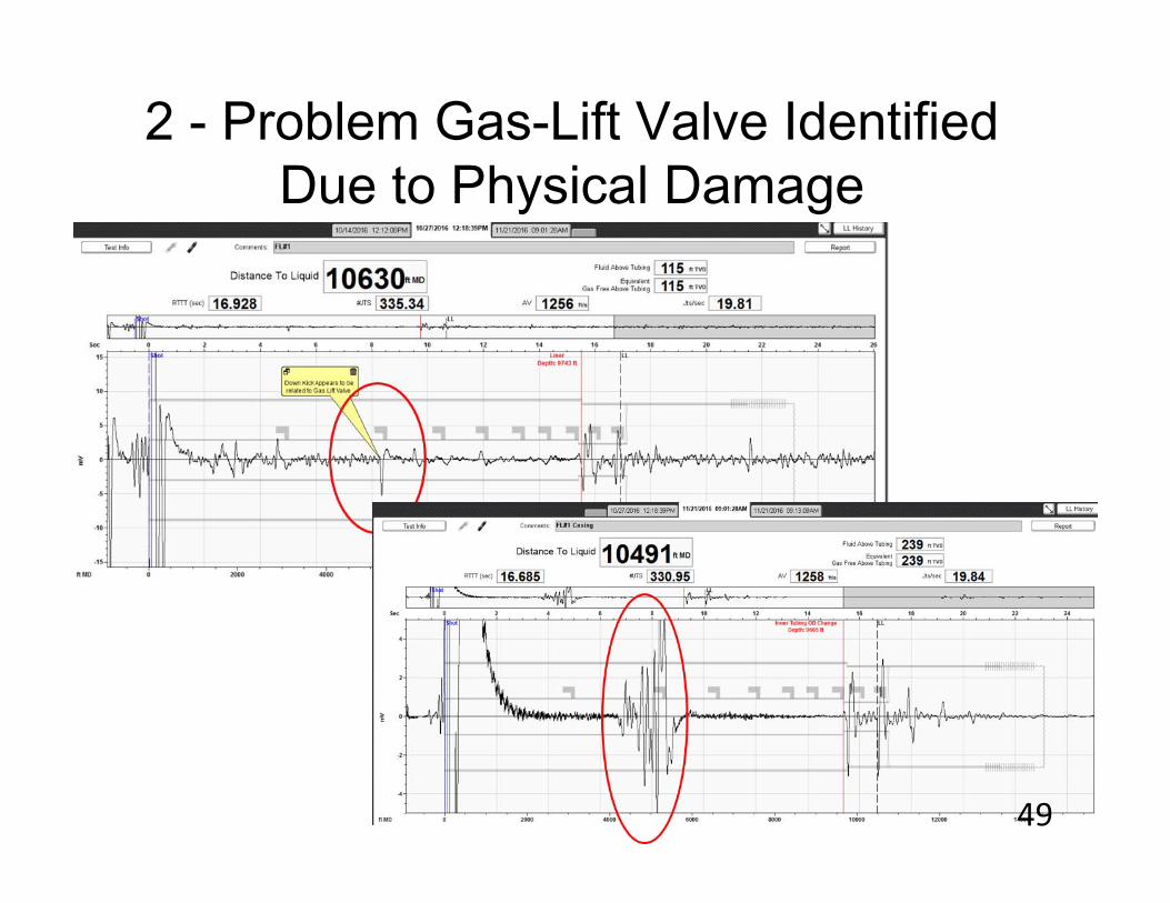
2 - Problem Gas-Lift Valve Identified Due to Physical Damage
• If the unloading valve has some type of physical damage and the echo is different, you will see it.
• However, if the internal parts of the valve are the same size and there is a pressure seal at the valve, then the echo at the valve will be the same and no difference will be seen.
• If the pressure seal fails, then it is likely that the echo at the valve will show a “strange kick” and you may be able to identify a valve with a problem.
48
2 - Problem Gas-Lift Valve Identified Due to Physical Damage
49
3 – The Dual Shot Method
Identifies communication between Tubing and Casing using Two Gas
Guns
50
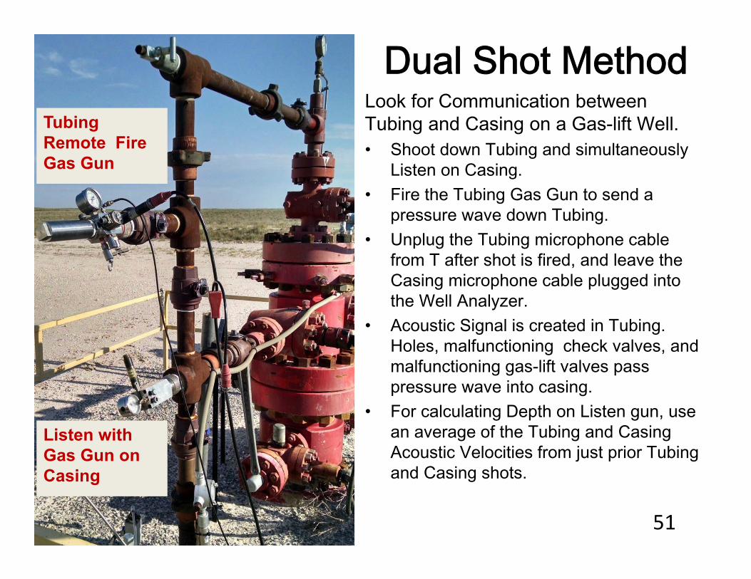
Dual Shot MethodLook for Communication between Tubing and Casing on a Gas-lift Well. • Shoot down Tubing and simultaneously
Listen on Casing.• Fire the Tubing Gas Gun to send a
pressure wave down Tubing. • Unplug the Tubing microphone cable
from T after shot is fired, and leave the Casing microphone cable plugged into the Well Analyzer.
• Acoustic Signal is created in Tubing. Holes, malfunctioning check valves, and malfunctioning gas-lift valves pass pressure wave into casing.
• For calculating Depth on Listen gun, use an average of the Tubing and Casing Acoustic Velocities from just prior Tubing and Casing shots.
Tubing Remote Fire Gas Gun
Listen with Gas Gun on Casing
51
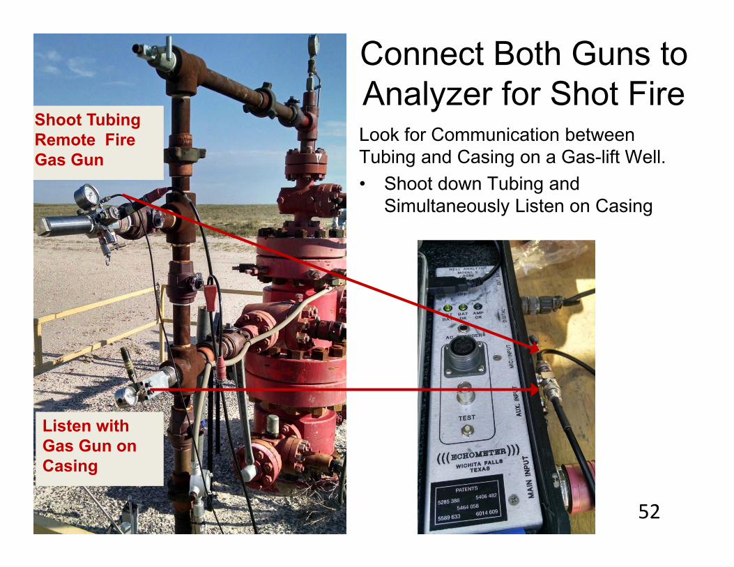
Connect Both Guns to Analyzer for Shot Fire
Shoot Tubing Remote Fire Gas Gun
Listen with Gas Gun on Casing
Look for Communication between Tubing and Casing on a Gas-lift Well. • Shoot down Tubing and
Simultaneously Listen on Casing
52
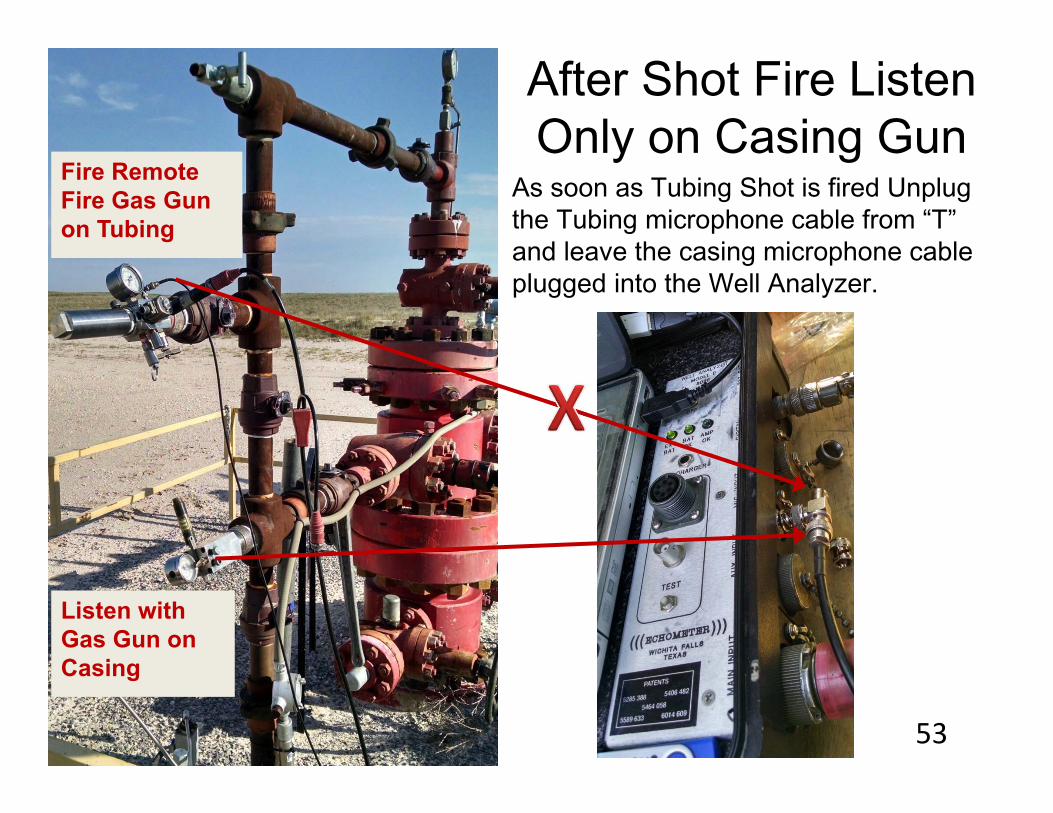
After Shot Fire Listen Only on Casing Gun
As soon as Tubing Shot is fired Unplug the Tubing microphone cable from “T” and leave the casing microphone cable plugged into the Well Analyzer.
Fire Remote Fire Gas Gun on Tubing
Listen with Gas Gun on Casing
53
Fire Shot Only
Listen and Record
1
2
3
4
5
678
91011
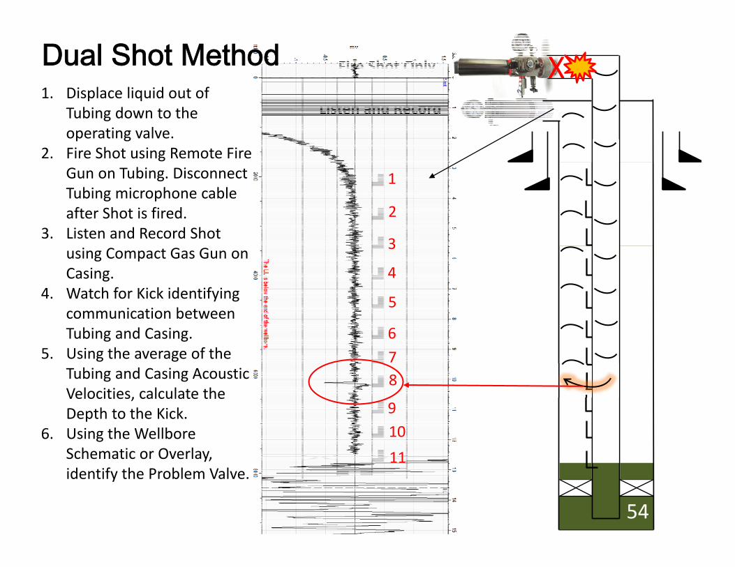
1. Displace liquid out of Tubing down to the operating valve.
2. Fire Shot using Remote Fire Gun on Tubing. Disconnect Tubing microphone cable after Shot is fired.
3. Listen and Record Shot using Compact Gas Gun on Casing.
4. Watch for Kick identifying communication between Tubing and Casing.
5. Using the average of the Tubing and Casing Acoustic Velocities, calculate the Depth to the Kick.
6. Using the Wellbore Schematic or Overlay, identify the Problem Valve.
Dual Shot Method X
54
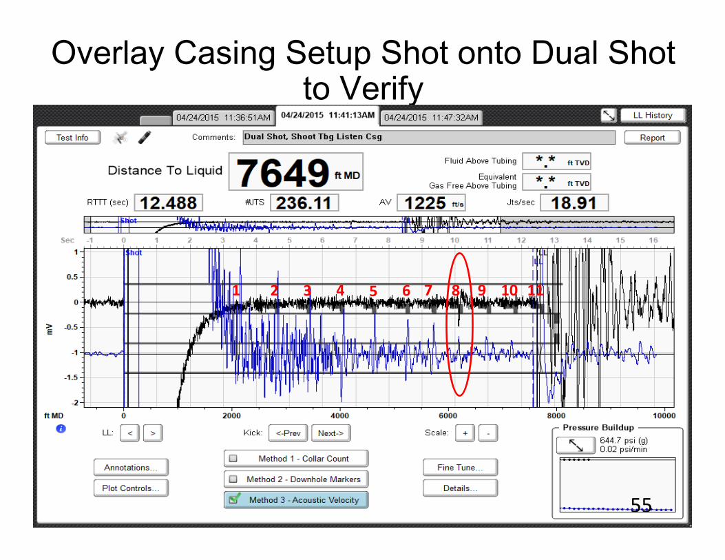
Overlay Casing Setup Shot onto Dual Shot to Verify
1 2 3 4 5 6 7 8 9 10 11
55
Dual Shot ResultsExample 1
56
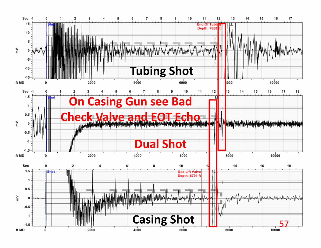
Tubing Shot
Casing Shot
Dual Shot
On Casing Gun see Bad Check Valve and EOT Echo
57
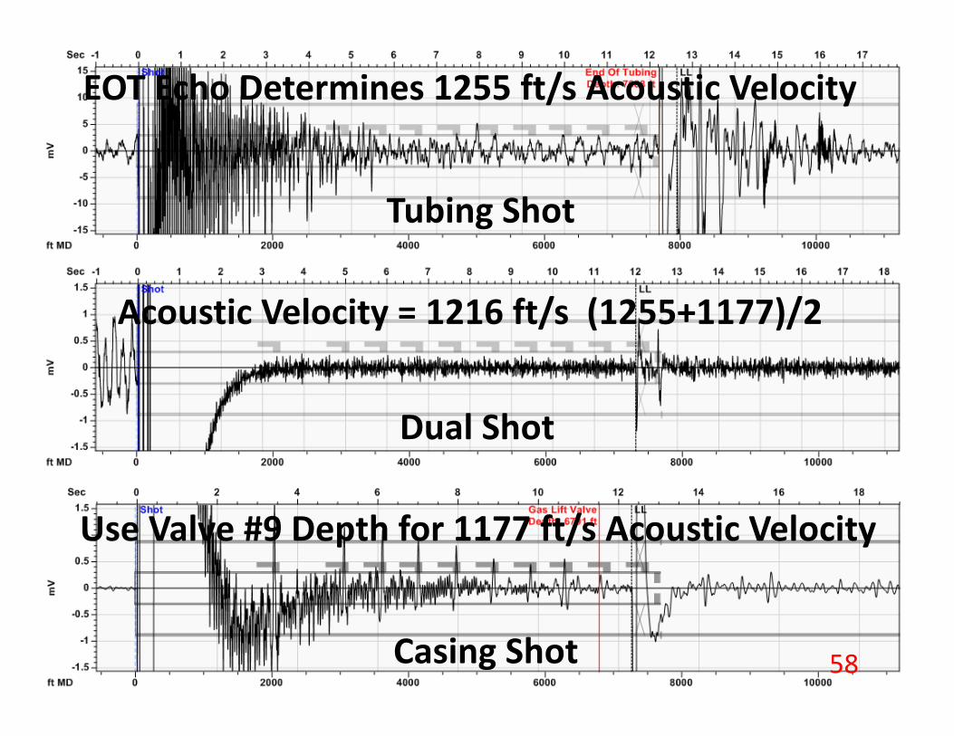
Tubing Shot
Casing Shot
Dual Shot
EOT Echo Determines 1255 ft/s Acoustic Velocity
Use Valve #9 Depth for 1177 ft/s Acoustic Velocity
Acoustic Velocity = 1216 ft/s (1255+1177)/2
58
Dual Shot ResultsExample 2
59
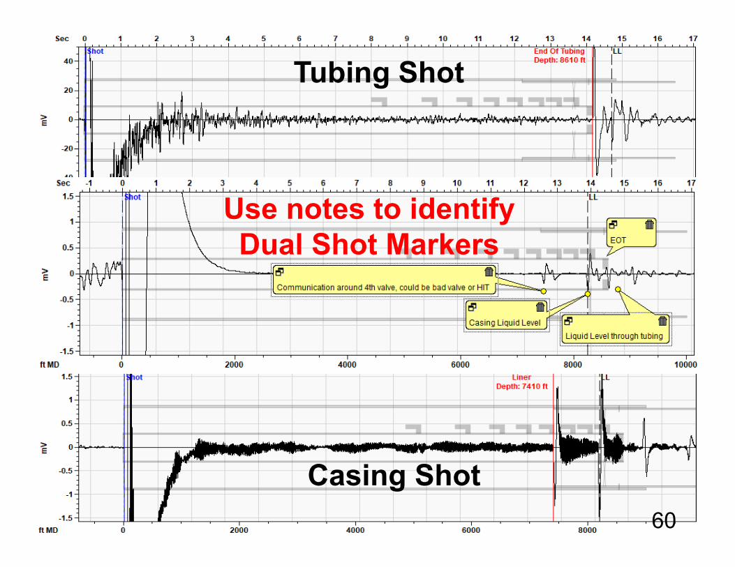
Tubing Shot
Use notes to identify Dual Shot Markers
Casing Shot60
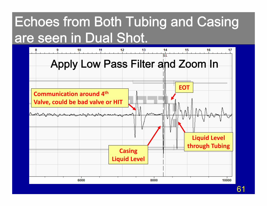
Echoes from Both Tubing and Casing are seen in Dual Shot.
Casing Liquid Level
EOTCommunication around 4thValve, could be bad valve or HIT
Liquid Level through Tubing
Apply Low Pass Filter and Zoom In
61

Dual Shot ResultsExample 3 – Wireless Equipment
Method Using Plunger Lift Application
62
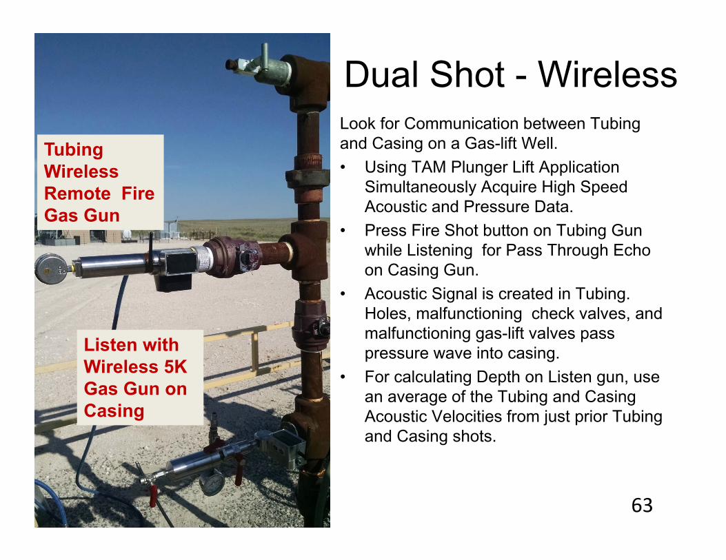
Dual Shot - Wireless Look for Communication between Tubing and Casing on a Gas-lift Well. • Using TAM Plunger Lift Application
Simultaneously Acquire High Speed Acoustic and Pressure Data.
• Press Fire Shot button on Tubing Gun while Listening for Pass Through Echo on Casing Gun.
• Acoustic Signal is created in Tubing. Holes, malfunctioning check valves, and malfunctioning gas-lift valves pass pressure wave into casing.
• For calculating Depth on Listen gun, use an average of the Tubing and Casing Acoustic Velocities from just prior Tubing and Casing shots.
Tubing Wireless Remote Fire Gas Gun
Listen with Wireless 5K Gas Gun on Casing
63
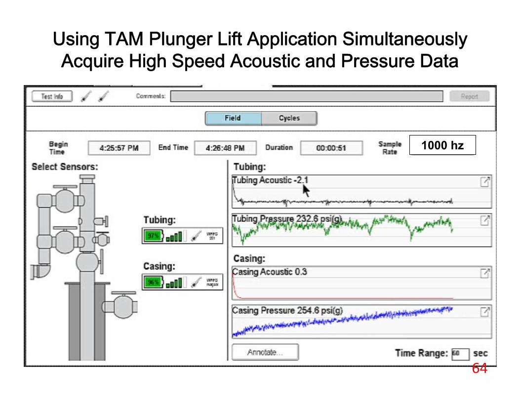
1000 hz
Using TAM Plunger Lift Application Simultaneously Acquire High Speed Acoustic and Pressure Data
64
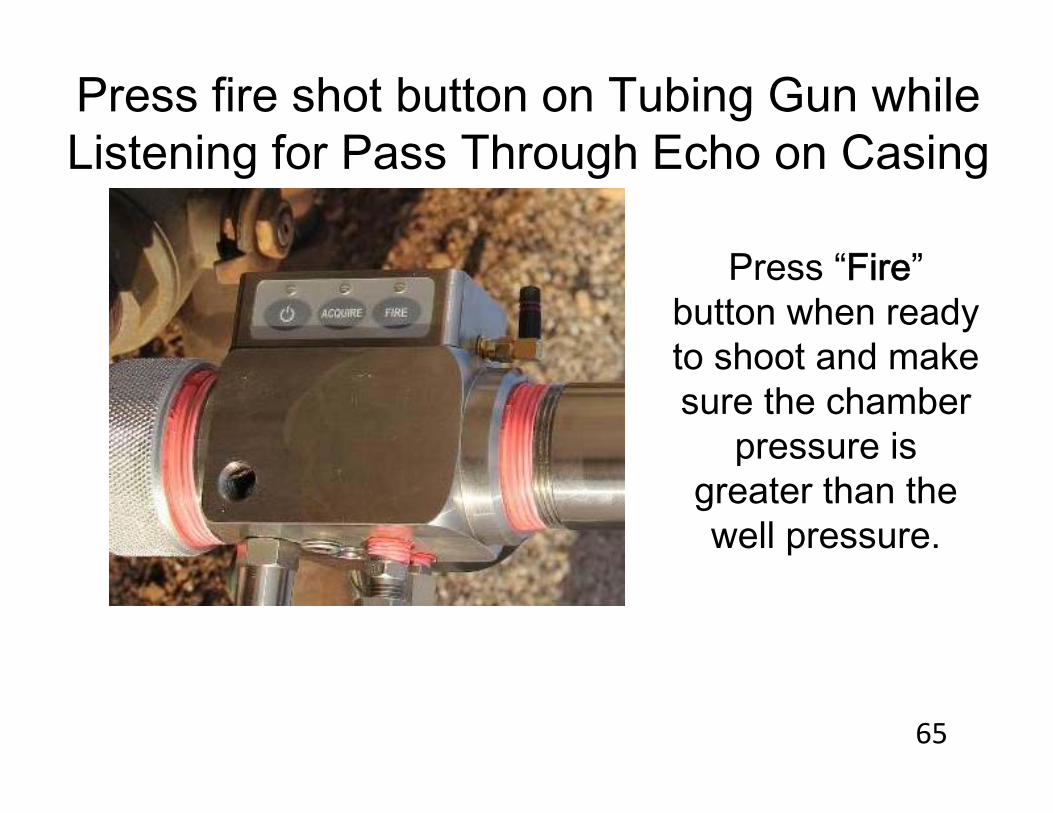
Press fire shot button on Tubing Gun while Listening for Pass Through Echo on Casing
Press “Fire” button when ready to shoot and make sure the chamber
pressure is greater than the well pressure.
65

Acoustic Signal is created in Tubing. If holes, leaky check valves,leaky gas-lift valves are present, then Tubing Pressure Waveenters Casing.
End of Tubing Echo Depth: 7688
Liquid Level Echo Depth: 7950
66
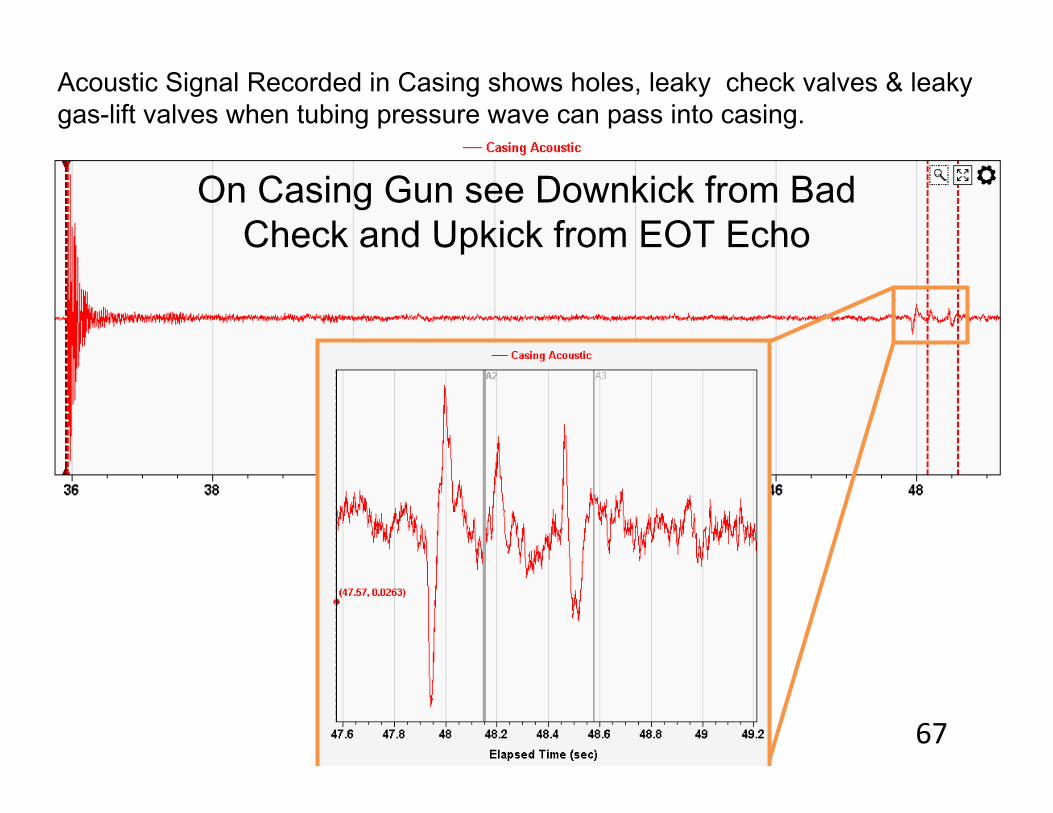
Acoustic Signal Recorded in Casing shows holes, leaky check valves & leaky gas-lift valves when tubing pressure wave can pass into casing.
On Casing Gun see Downkick from Bad Check and Upkick from EOT Echo
67
Conclusion• Beneficial information is obtained throughout the life of a
gas-lift well by determining the distance to the fluid level. • Knowing the Acoustic Velocity profile of a well provides
critical information for verifying gas composition and fluid level accuracy.
• Identifying reflection kicks across valves and mandrels result in more accurate depth analysis.
• Operating valves are identified quickly and easily .• Troubleshooting techniques aid in identifying downhole
problems.
68
Acoustic Techniques for Gas-Lift Wells
Thank you for joining us for today!
Ask Echometer Online Session – June 17, 2020
Questions?
69