Embed Size (px)
Citation preview

ACOUSTIC REPORT
FOR
THE ICON HAMILTON
EMF GRIFFITHS
Consulting Engineers
PROPERTY DEVELOPMENT SYSTEMS AUSTRALIA
Client
ISSUE B
July 25 2014
Project No. S214631


EMF GRIFFITHS – SUSTAINABILITY CONSULTANTS
The Icon, Hamilton iiAcoustic Report – Issue B S214631AcousticRevB-gbr – July 25 2014
INDEX
SECTION 1.0 SITE DESCRIPTION ................................................................................................................ 1
1.1 INTRODUCTION ...................................................................................................................... 1
1.2 BACKGROUND ....................................................................................................................... 2
1.3 OBJECTIVES ........................................................................................................................... 2
1.4 SUBJECT SITE - LOCATION AND DESCRIPTION ................................................................ 2
1.5 NEAREST NOISE SENSITIVE RECEIVERS ........................................................................... 5
SECTION 2.0 GENERAL AMENITY ISSUES ................................................................................................ 6
2.1 EXISTING NOISE AMENITY ................................................................................................... 6
2.2 NOISE SOURCES ................................................................................................................... 7
SECTION 3 ACOUSTIC DESIGN CRITERIA ............................................................................................ 17
3.1 NOISE LEVELS AND REVERBERATION TARGETS ........................................................... 17
3.2 ACOUSTIC SEPARATION TARGETS ................................................................................... 18
3.3 SERVICES ACOUSTIC TARGETS ........................................................................................ 20
SECTION 4 NOISE INTRUSION ASSESSMENT (FACADE CALCULATION) ......................................... 21
4.1 NOISE CALCULATION METHODOLOGY ............................................................................. 21
4.2 NOISE CALCULATION RESULTS ........................................................................................ 21
SECTION 5 RECOMMENDATIONS .......................................................................................................... 24
5.1 FACADE TREATMENTS ....................................................................................................... 24
5.2 ACOUSTIC SEPARATION TREATMENTS ........................................................................... 24
5.3 SERVICES TREATMENTS .................................................................................................... 25
5.4 LIFT CORE TREATMENTS ................................................................................................... 26
SECTION 6 CONCLUSION ....................................................................................................................... 27

EMF GRIFFITHS – SUSTAINABILITY CONSULTANTS
The Icon, Hamilton 1Acoustic Report – Issue B S214631AcousticRevB-gbr – July 25 2014
SECTION 1.0 SITE DESCRIPTION 1.1 INTRODUCTION
EMF Griffiths have been engaged by Wentworth Equities Pty Ltd to provide acoustic consultancy for the architectural and building services of the proposed mixed use development at “The Icon”, 19 Hercules Street, Hamilton described as Lot 3 on SP172658. The development proposal comprises four buildings that rise from a retail plaza. The proposed scheme contains a diverse mix of building heights, apartment types and uses that activate the frontages. The site masterplan comprises four buildings:- Tower 1: 33 storey mixed use hotel and residential tower Tower 2: 28 storey residential tower Tower 3: 8 storey residential tower Tower 4: 15 storey residential tower Car parking is provided in a seven level basement with spaces for residents, retail tenants, hotel guests and visitors. The proposed mix is as follows:- Studio apartments: 74 1 bed apartments: 279 2 bed apartments: 176 3 bed apartments: 31 Total apartments: 560 units Hotel Suites: 227 Retail GFA: 4,746m² Residential GFA: 41,496m² Hotel GFA: 13,178m² Total GFA: 59,420m
Figure 1: Site Plan

EMF GRIFFITHS – SUSTAINABILITY CONSULTANTS
The Icon, Hamilton 2Acoustic Report – Issue B S214631AcousticRevB-gbr – July 25 2014
1.2 BACKGROUND An acoustic assessment for noise intrusion to maintain appropriate levels of amenity for the building residents and users is required along with assessment of impact on adjacent noise sensitive receivers. The assessment reviews building layout drawings, mechanical services, architectural schedules and proposes acoustic design recommendation with respect to the acoustic requirements of :-
Local and State Regulations propose acoustic design recommendations including requirements of Brisbane City Council (BCC) Noise Impact Assessment Planning Scheme Policy (NIAPSP) and the State Environmental Protection (Noise) Policy 2008.
The BCA 2014 section F5.
Australian Standard AS2107.
1.3 OBJECTIVES Acoustic study as follows:-
Identification of target internal noise levels.
Identification of noise emissions targets.
Characterisation of noise emissions associated with the external mechanical plant (including pumps, fans and chiller noise) and activities (e.g. waste and on site vehicle movements, outdoor space noise emissions from site occupants) associated with the development.
Characterisation of noise from external sounds such as nearby roads, aircraft noise and industrial sources.
Acoustic Modelling, calculations and recommendations for appropriate noise amelioration measures to mitigate noise impact for the building residents and building users.
Acoustic design in accordance with requirements of the Building Code of Australia.
Acoustic Design of Noise Control Measures for Mechanical Ventilation. The noise emanating from the mechanical ventilation system shall be in accordance with the requirements of Appendix B of the Australia Standard AS 1055.2-1984 (Description and Measurement of Environmental Noise).
Acoustic design based on measured environmental noise statistical noise characterisation parameters, as defined in AS1055.1-3 1997 accounting for:-
- Tonality.
- Frequency weighting.
- Impulsive characteristics.
- Fluctuations and temporal content.
- Recommended maximum planning noise levels.
1.4 SUBJECT SITE - LOCATION AND DESCRIPTION
The development proposal comprises four buildings that rise from a retail plaza. The proposed scheme contains a diverse mix of building heights, apartment types and uses that activate the frontages. The site is located in Hamilton, Queensland. The site and location are shown in the Google satellite image in Figure 2.

EMF GRIFFITHS – SUSTAINABILITY CONSULTANTS
The Icon, Hamilton 3Acoustic Report – Issue B S214631AcousticRevB-gbr – July 25 2014
Figure 2: Aerial View of Subject Site The site is located in the Portside EDQ Precinct which is a residential/ mixed use area of Hamilton as shown in the zoning map below.
Figure 3: Extract From BCC City Plan 2014 Zoning Map
Subject Site
Subject Site
EMF GRIFFITHS – SUSTAINABILITY CONSULTANTS
The Icon, Hamilton 4Acoustic Report – Issue B S214631AcousticRevB-gbr – July 25 2014
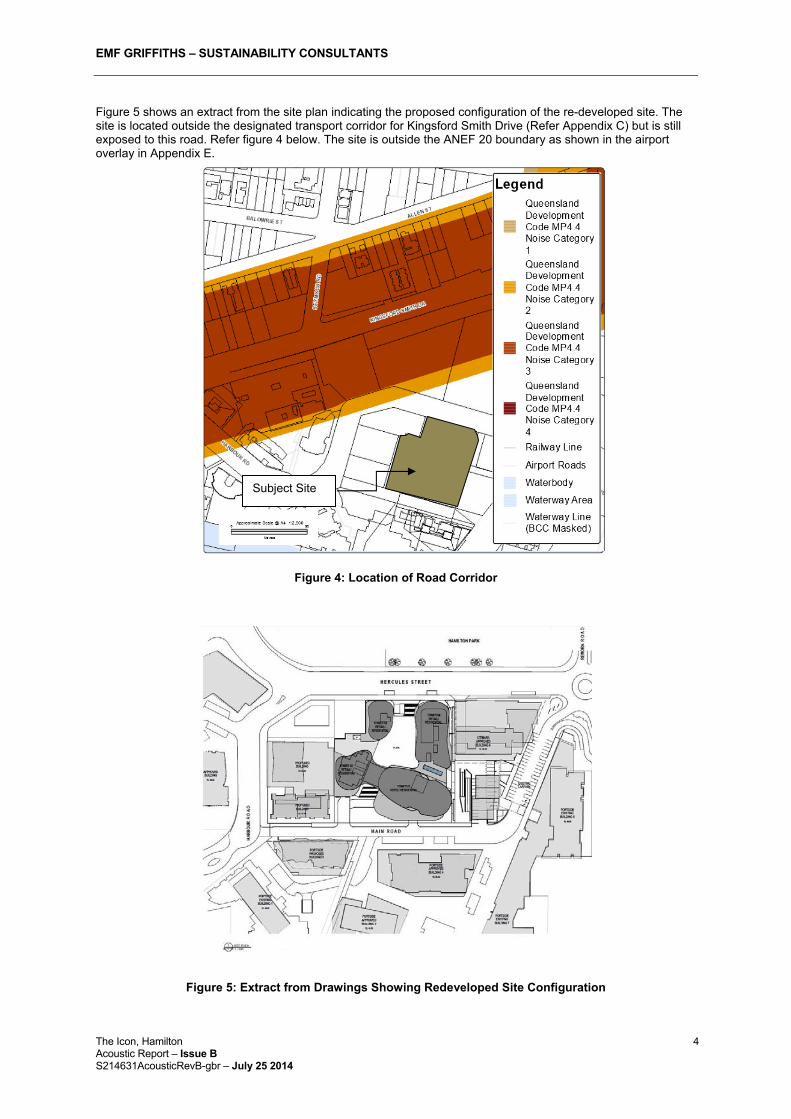
Figure 5 shows an extract from the site plan indicating the proposed configuration of the re-developed site. The site is located outside the designated transport corridor for Kingsford Smith Drive (Refer Appendix C) but is still exposed to this road. Refer figure 4 below. The site is outside the ANEF 20 boundary as shown in the airport overlay in Appendix E.
Figure 4: Location of Road Corridor
Figure 5: Extract from Drawings Showing Redeveloped Site Configuration
Subject Site
EMF GRIFFITHS – SUSTAINABILITY CONSULTANTS
The Icon, Hamilton 5Acoustic Report – Issue B S214631AcousticRevB-gbr – July 25 2014
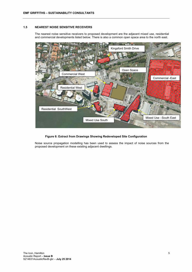
1.5 NEAREST NOISE SENSITIVE RECEIVERS
The nearest noise sensitive receivers to proposed development are the adjacent mixed use, residential and commercial developments listed below. There is also a common open space area to the north east.
Figure 6: Extract from Drawings Showing Redeveloped Site Configuration Noise source propagation modelling has been used to assess the impact of noise sources from the proposed development on these existing adjacent dwellings.
Residential SouthWest
Commercial West
Mixed Use South
Kingsford Smith Drive
Open Space
Residential West
Commercial -East
Mixed Use –South East

EMF GRIFFITHS – SUSTAINABILITY CONSULTANTS
The Icon, Hamilton 6Acoustic Report – Issue B S214631AcousticRevB-gbr – July 25 2014
SECTION 2.0 GENERAL AMENITY ISSUES
2.1 EXISTING NOISE AMENITY
Typical Noise Levels at the subject site (see Figure below) are shown in the table below. Noise sources at the subject site are:-
Traffic Noise from adjacent roads, Kingsford Smith Drive, Remora Road and Hercules Street.
Vehicle noise from passenger and commercial vehicles entering and leaving the area.
Noise from planes flying overhead.
Noise from users of the adjacent sites and commercial properties
The Rating Background Noise Levels (RBL) typical of the area are summarised below:- Period Time Noise Level dB(A)
LAeq-1hour LA90-1hour LA10-1hour Day 0700-1800 55 52 58
Evening 1800-2200 51 48 54
Night 2200-0700 49 46 52
Table 3: Typical Noise Data for Area
L10-1hr max 7am-6pm L10 1hr max 6pm-10pm L10 1hr max 10pm-7am
63 62 52 Table 4: Noise Survey Results

EMF GRIFFITHS – SUSTAINABILITY CONSULTANTS
The Icon, Hamilton 7Acoustic Report – Issue B S214631AcousticRevB-gbr – July 25 2014
2.2 NOISE SOURCES There are a variety of noise sources at the proposed development including:-
Mechanical Plant Noise from car park fan intakes and exhausts at the lower levels.
Noise from operation of mechanical services – note the development has a centralised water cooled A/C system with all major mechanical items mounted at roof level (level 15 & 16 of tower 4).
Noise from operation of kitchen exhausts from retail area where retail areas require a kitchen. These are to be discharged horizontally at the roof level of the retail tenancy.
Noise transmitted by internal building services and pipework.
Noise from waste vehicles and loading vehicles at ground level. Note the loading dock and waste area is located within the basement so noise emissions due to these activities are largely contained within the development.
Noise from passenger vehicles entering and leaving the car park at ground level.
Noise from users of the commercial areas, hotel areas, common areas and private outdoor areas.
The following section identifies the location and levels of the significant noise sources which have been considered in the assessment. The figures below show the location of the noise sources.
Figure 7: Level 1 - Ground
Key Vehicle Noise Pedestrian Noise
Recreation Noise
Roller Door Noise Condenser/Fans
Waste Collection

EMF GRIFFITHS – SUSTAINABILITY CONSULTANTS
The Icon, Hamilton 8Acoustic Report – Issue B S214631AcousticRevB-gbr – July 25 2014
Figure 8: Hotel Lobby
Key Vehicle Noise Pedestrian Noise
Recreation Noise
Roller Door Noise Condenser/Fans
Waste Collection

EMF GRIFFITHS – SUSTAINABILITY CONSULTANTS
The Icon, Hamilton 9Acoustic Report – Issue B S214631AcousticRevB-gbr – July 25 2014
Figure 9: Plaza Level
Key Vehicle Noise Pedestrian Noise
Recreation Noise
Roller Door Noise Condenser/Fans
Waste Collection

EMF GRIFFITHS – SUSTAINABILITY CONSULTANTS
The Icon, Hamilton 10Acoustic Report – Issue B S214631AcousticRevB-gbr – July 25 2014
Figure 10: Podium Level
Key Recreation Noise Fan/ Pump/Condenser

EMF GRIFFITHS – SUSTAINABILITY CONSULTANTS
The Icon, Hamilton 11Acoustic Report – Issue B S214631AcousticRevB-gbr – July 25 2014
Figure 11: Typical Low Level
Key
Recreation Noise

EMF GRIFFITHS – SUSTAINABILITY CONSULTANTS
The Icon, Hamilton 12Acoustic Report – Issue B S214631AcousticRevB-gbr – July 25 2014
Figure 12: Typical Mid Level
Key
Recreation Noise

EMF GRIFFITHS – SUSTAINABILITY CONSULTANTS
The Icon, Hamilton 13Acoustic Report – Issue B S214631AcousticRevB-gbr – July 25 2014
Figure 13: Typical High Level
Key
Recreation Noise

EMF GRIFFITHS – SUSTAINABILITY CONSULTANTS
The Icon, Hamilton 14Acoustic Report – Issue B S214631AcousticRevB-gbr – July 25 2014
Figure 14: Level 15 and 16 Plant Deck Levels
2.2.1 Mechanical Plant
External Noise Intrusion, generally from plant noise, is considered in this report. In most cases the transmission path will be via airborne noise. In some circumstances, regenerated noise as a result of vibration may also be an issue. Intrusive noise can generally be classified as either continuous or intermittent. Continuous noise, even though it might vary from time to time, is measured using a procedure to determine its equivalence over a representative time period. The continuous measurement is normally expressed as LAeq whereas intermittent noise is measured as the arithmetic average of the maximum sound level readings expressed as LAmax,avg. Mechanical Plant Equipment comprises continuous noise sources as follows:-
Key Condenser/Fans

EMF GRIFFITHS – SUSTAINABILITY CONSULTANTS
The Icon, Hamilton 15Acoustic Report – Issue B S214631AcousticRevB-gbr – July 25 2014
Sound Power (dB) at Octave Band (Hz)Equipment No. Oper. Loc. 63 125 250 500 1k 2k 4k 8k SPL
dB(A) @3m
Fans Car Park Supply air fan– note Lw levels are shown in dB
2 CPSAF-1 (VSDs50%6-8hrs,18-20hrs)
Ground floor
88 84 88 83 85 85 81 73 70 @3m
Car Park Exhaust fan– note Lw levels are shown in dB
2 CPEF-2 (VSDs50%6-8hrs,18-20hrs)
Ground floor
76 86 92 87 80 72 65 60 67@3m
Retail Kitchen Exhaust 1 Bus. Hrs Retail Lvl. 90 93 94 93 95 93 79 @ 1m Cooling Towers Full Speed - Large 3 Bus. Hrs. Roof – Lvl
16 Twr 4 107 105 100 92 88 82 77 68 76dB(A)
@1.5m Full Speed - Small 2 24/7 Roof – Lvl
16 Twr 4 103 103 100 97 91 87 83 76 79dB(A)
@1.5m Chillers (in plant room) Full Speed -Large 2 Bus. Hrs. Roof 79 78 81 82 86 82 75 79 81@1m Full Speed –Small 1 24/7 Roof 68 83 79 76 81 75 77 76 77@1m Pumps Chilled Water Pump 2 Bus. Hrs. Roof - - - - - - - - 69@1m Chilled Water Pump 1 Bus. Hrs. Roof - - - - - - - - 67@1m Condenser Water Pump
2 Bus. Hrs. Roof - - - - - - - - 69@1m
Condenser Water Pump
1 Bus. Hrs. Roof - - - - - - - - 67@1m
* C.M. Harris - Acoustical Measurements and Noise Control, 1991 **Manufacturers Data Table 3: Sound Power and Number of Major Items of Mechanical Plant

EMF GRIFFITHS – SUSTAINABILITY CONSULTANTS
The Icon, Hamilton 16Acoustic Report – Issue B S214631AcousticRevB-gbr – July 25 2014
2.2.2 Waste and Car Park Vehicle Movements
The car parks are located in the basement car park. Waste collection is by an 8.5m medium rigid rear loading waste truck at the waste storage area within the basement. The noise due to entrance and exiting of the vehicles (reversing alarms, vehicles accelerating and starting) has been modelled. These noise sources are intermittent and typical sound levels from these events are shown below:-
Description LAmax Waste Vehicle Movement* for ¼ hour between 7am and 8am 100dB(A) Internal Car Movement (entering/leaving)*** 150 movements/hour between 6am-10am and 4pm-7pm and between 20 and 50 movements/hour at other times
94dB(A)
* Truck and loading noise on operating ground of cargo centres, delivery warehouses and haulage contractors, Hessische Landesanstalt für Umwelt, 16.05.1995 Heft 192 ** Forum Schall – emissions data catalogue *** 2000-04-23/JKl, DELTA Acoustics and Vibration, Danish Acoustical Institute, DK-2800 Lyngby
Table 4: Sound Levels of Waste and Internal Car Park Movements
2.2.3 Common Area Use and Private Outdoor Spaces
The associated intermittent noise sources from use of the common areas and commercial outdoor areas and private outdoor spaces associated with each unit are detailed in the table below:-
Description LAeq People talking (loud conversation)* 70dB(A)
* Technischer Überwachungs-Verein Norddeutschland e.V., 1987
Table 5: Sound Levels of Common Area noise Sources 2.2.4 Traffic Noise
The traffic noise levels, within an ultimate planning horizon of 20 years from the establishment of the proposed development (year 2016), were predicted using the noise prediction model SoundPLAN. Calculations are based on the procedures developed by the U.K. Department of Transport, Welsh Office, issued as “Calculation of Road Traffic Noise” in 1988 (CoRTN’88). The dominant traffic noise source is Kingsford Smith Drive. The traffic flows are presented in the table:_
2035 Traffic Flow AADT Heavy Vehicles (%)77,000 6%
The predicted traffic flows were scaled down by a factor of 0.95, to represent the 95-percentile traffic flow in an 18-hour period between 6:00 a.m. and 12:00 midnight.
Table 6: Traffic Flows

EMF GRIFFITHS – SUSTAINABILITY CONSULTANTS
The Icon, Hamilton 17Acoustic Report – Issue B S214631AcousticRevB-gbr – July 25 2014
SECTION 3 ACOUSTIC DESIGN CRITERIA 3.1 NOISE LEVELS AND REVERBERATION TARGETS
Under performance criteria of the BCC city plan high density design code the development is required to comply with the requirements of the noise impact assessment planning scheme policy (NIAPSP) the NIAPSP criteria are summarised in the table below:- Methodology Applicable Noise Level and Criteria Comparisons of like parameters
Waste collection vehicles, Noise from development not exceed the LA10 parameter describing the ambient noise by more than 3dB(A).
Application of AS2107 Refer Tables 8 and 9 for applicable levels for steady state noise such as from air A/C condensers and continuous road noise.
Sleep Awakening Sound Exposure Level LAE to be less than 65dB(A) at Bedroom facades from noise from other residents.
Background Creep Not to exceed existing LA90 level at site. Table 7: NIAPSP and Methodologies
The site is outside the zones requiring specific treatment required by MP4.4 buildings in a Transport Noise Corridor – Refer map in Appendix C. Noise intrusion criteria applicable to the residential areas of the development as required by the EPP (2008) have been summarised in Table 10 below.
Authority Item Applicable
Area Descriptor Noise Goal,dB(A)
The Environmental Protection (Noise) Policy 2008
Acoustic Quality Objective in private outdoor space
Outdoor Space of Dwelling
LAeq,adj,1hr
LA10,adj,1hr
LA1,adj,1hr
50 55 65
Acoustic Quality Objective in dwelling during daytime (0700-1800) and evening (1800-2200)
Indoor LAeq,adj,1hr
LA10,adj,1hr
LA1,adj,1hr
35 40 45
Acoustic Quality Objective in dwelling during night (2200-0700)
Indoor LAeq,adj,1hr
LA10,adj,1hr
LA1,adj,1hr
30 35 40
Table 8: Noise Intrusion Criteria
In addition, the Australian Standard AS/NZS 2107:2000 recommends the following interior noise level targets for residential areas:-
Authority Applicable Area Descriptor Noise Goal,dB(A) AS/NZS 2107:2000
Acoustic Quality Objective in dwelling during day
Living Areas LAeq 45
Acoustic Quality Objective in dwelling during night (2200-0700)
Sleeping areas LAeq (1-hour max) 40
Table 9: Additional Noise Intrusion Criteria
EMF GRIFFITHS – SUSTAINABILITY CONSULTANTS
The Icon, Hamilton 18Acoustic Report – Issue B S214631AcousticRevB-gbr – July 25 2014
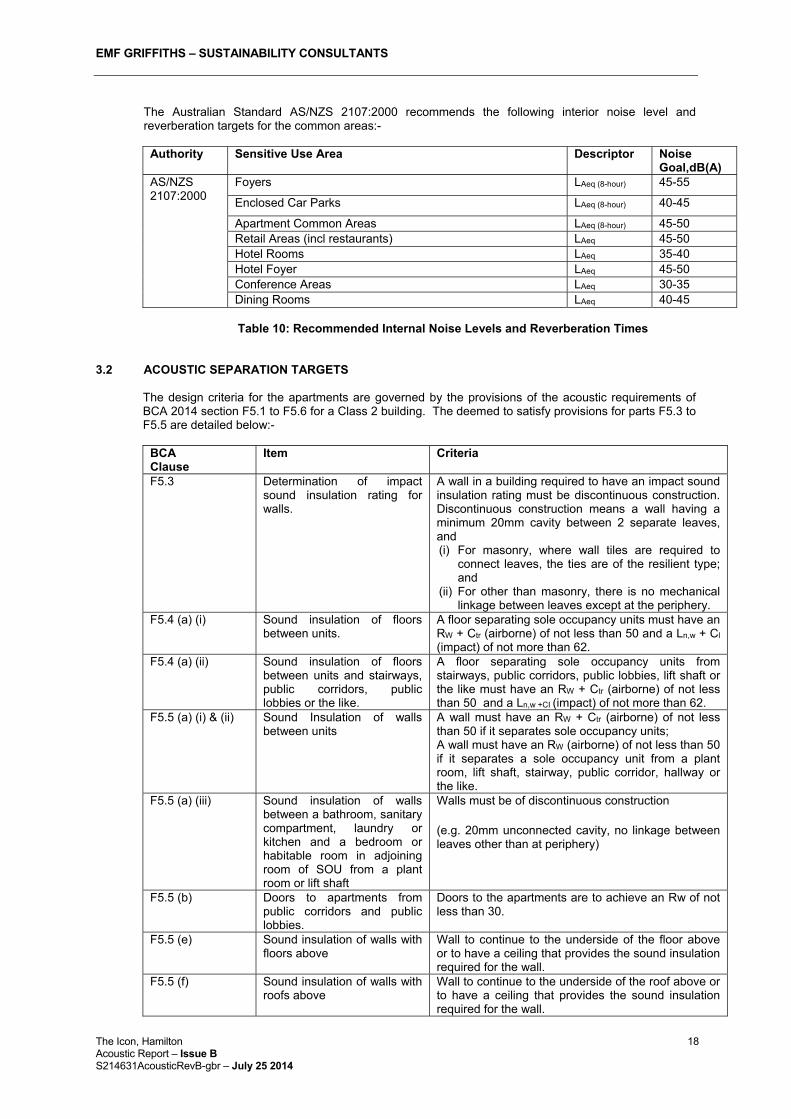
The Australian Standard AS/NZS 2107:2000 recommends the following interior noise level and reverberation targets for the common areas:-
Authority Sensitive Use Area Descriptor Noise
Goal,dB(A) AS/NZS 2107:2000
Foyers LAeq (8-hour) 45-55
Enclosed Car Parks LAeq (8-hour) 40-45
Apartment Common Areas LAeq (8-hour) 45-50 Retail Areas (incl restaurants) LAeq 45-50 Hotel Rooms LAeq 35-40 Hotel Foyer LAeq 45-50 Conference Areas LAeq 30-35 Dining Rooms LAeq 40-45
Table 10: Recommended Internal Noise Levels and Reverberation Times
3.2 ACOUSTIC SEPARATION TARGETS
The design criteria for the apartments are governed by the provisions of the acoustic requirements of BCA 2014 section F5.1 to F5.6 for a Class 2 building. The deemed to satisfy provisions for parts F5.3 to F5.5 are detailed below:-
BCA Clause
Item Criteria
F5.3 Determination of impact sound insulation rating for walls.
A wall in a building required to have an impact sound insulation rating must be discontinuous construction. Discontinuous construction means a wall having a minimum 20mm cavity between 2 separate leaves, and (i) For masonry, where wall tiles are required to
connect leaves, the ties are of the resilient type; and
(ii) For other than masonry, there is no mechanical linkage between leaves except at the periphery.
F5.4 (a) (i) Sound insulation of floors between units.
A floor separating sole occupancy units must have an RW + Ctr (airborne) of not less than 50 and a Ln,w + Cl (impact) of not more than 62.
F5.4 (a) (ii) Sound insulation of floors between units and stairways, public corridors, public lobbies or the like.
A floor separating sole occupancy units from stairways, public corridors, public lobbies, lift shaft or the like must have an RW + Ctr (airborne) of not less than 50 and a Ln,w +CI (impact) of not more than 62.
F5.5 (a) (i) & (ii) Sound Insulation of walls between units
A wall must have an RW + Ctr (airborne) of not less than 50 if it separates sole occupancy units; A wall must have an RW (airborne) of not less than 50 if it separates a sole occupancy unit from a plant room, lift shaft, stairway, public corridor, hallway or the like.
F5.5 (a) (iii) Sound insulation of walls between a bathroom, sanitary compartment, laundry or kitchen and a bedroom or habitable room in adjoining room of SOU from a plant room or lift shaft
Walls must be of discontinuous construction
(e.g. 20mm unconnected cavity, no linkage between leaves other than at periphery)
F5.5 (b) Doors to apartments from public corridors and public lobbies.
Doors to the apartments are to achieve an Rw of not less than 30.
F5.5 (e) Sound insulation of walls with floors above
Wall to continue to the underside of the floor above or to have a ceiling that provides the sound insulation required for the wall.
F5.5 (f) Sound insulation of walls with roofs above
Wall to continue to the underside of the roof above or to have a ceiling that provides the sound insulation required for the wall.

EMF GRIFFITHS – SUSTAINABILITY CONSULTANTS
The Icon, Hamilton 19Acoustic Report – Issue B S214631AcousticRevB-gbr – July 25 2014
BCA Clause
Item Criteria
F5.6 Sound Insulation Rating of Services
If a duct, soil, waste or water supply pipe, including a duct or pipe that is located in a wall or floor cavity, serves or passes through more than one sole-occupancy unit, the duct or pipe must be separated from the rooms of any sole-occupancy unit by construction with an Rw + Ctr (airborne) not less than – (i) 40 if the adjacent room is a habitable room (other
than a kitchen); or (ii) 25 of the adjacent room is a kitchen or non-
habitable room. (b) If a storm water pipe passes through a sole-
occupancy unit it must be separated in accordance with (i) and (ii).
F5.7 Sound Isolation of Pumps Flexible couplings to be used at the point of connection between the service pipes in the build and any circulating or other pump.
Table 11: BCA 2014 Acoustic Design Criteria
All forms of construction detailed in table 11 must be installed as follows:-
(a) Masonry – Units must be laid with all joints filled solid, including those between the masonry and any adjoining construction.
(b) Concrete slabs – Joints between concrete slabs or panels and any adjoining construction must be filled solid.
(c) Sheeting materials:-
(i) If one layer is required on both sides of a wall, it must be fastened to the studs with joints staggered on opposite sides.
(ii) If two layers are required the second layer must be fastened over the first layer so that the joints do not coincide with those of the first layer.
(iii) Joints between sheets or between sheets and any adjoining construction must be taped and filled solid.
(d) Timber or steel-framed construction – perimeter framing members must be securely fixed to the adjoining structure and:-
(i) Bedded in resilient compound.
(ii) The joints must be caulked so that there are no voids between the framing members and the adjoining structure.
(e) Services:-
(i) Services must not be chased into concrete or masonry elements. (ii) A door or panel required to have a certain Rw + Ctr that provides access to a duct, pipe
or other services must:-
- Not open into any habitable room (other than a kitchen); and
- Be firmly fixed so as to overlap the frame or rebate of the frame by not let than 10mm, be fitted with a sealing gasket along all edges and be constructed of:-
Wood, particleboard or blockboard not less than 33mm thick; or
Compressed fibre reinforced cement sheeting not less than 9mm thick; or
Other suitable material with a mass per unit area not less than 24.2 kg/m2.
(f) A water supply pipe must –
- Only be installed in the cavity of discontinuous construction; and
EMF GRIFFITHS – SUSTAINABILITY CONSULTANTS
The Icon, Hamilton 20Acoustic Report – Issue B S214631AcousticRevB-gbr – July 25 2014
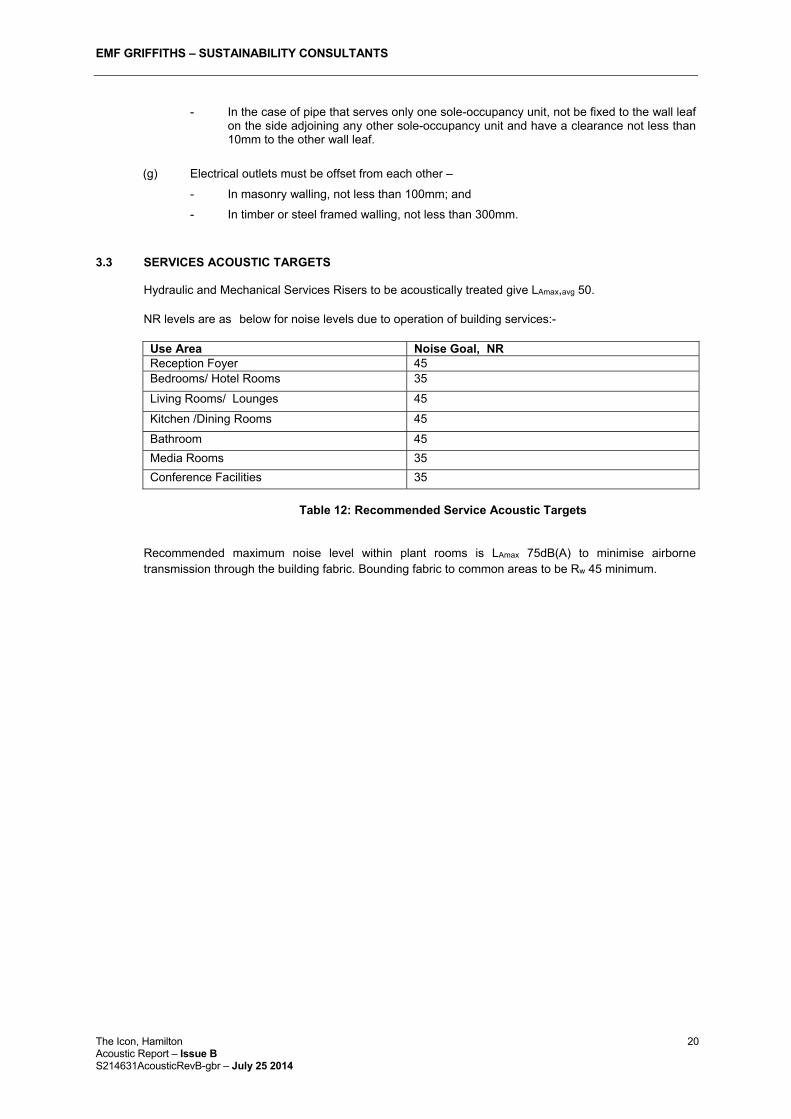
- In the case of pipe that serves only one sole-occupancy unit, not be fixed to the wall leaf on the side adjoining any other sole-occupancy unit and have a clearance not less than 10mm to the other wall leaf.
(g) Electrical outlets must be offset from each other –
- In masonry walling, not less than 100mm; and
- In timber or steel framed walling, not less than 300mm.
3.3 SERVICES ACOUSTIC TARGETS
Hydraulic and Mechanical Services Risers to be acoustically treated give LAmax,avg 50.
NR levels are as below for noise levels due to operation of building services:-
Use Area Noise Goal, NRReception Foyer 45 Bedrooms/ Hotel Rooms 35
Living Rooms/ Lounges 45
Kitchen /Dining Rooms 45
Bathroom 45
Media Rooms 35
Conference Facilities 35
Table 12: Recommended Service Acoustic Targets
Recommended maximum noise level within plant rooms is LAmax 75dB(A) to minimise airborne transmission through the building fabric. Bounding fabric to common areas to be Rw 45 minimum.

EMF GRIFFITHS – SUSTAINABILITY CONSULTANTS
The Icon, Hamilton 21Acoustic Report – Issue B S214631AcousticRevB-gbr – July 25 2014
SECTION 4 NOISE INTRUSION ASSESSMENT (FACADE CALCULATION) 4.1 NOISE CALCULATION METHODOLOGY
4.1.1 Computer Modelling Method A three dimensional model was created using SoundPLAN noise propagation software. The noise sources identified in section 2 were added to the model in the appropriate locations. A three dimensional noise map of the noise levels due to the sources was calculated. In addition, noise levels were calculated at designated locations the building facades, common areas and private outdoor spaces.
4.1.2 Sound Power Levels of the Main Noise Sources
Sound Power Levels of the main sources, as detailed in Section 2.2 were input into the model at the proposed locations.
4.1.3 Tonality and Impulsiveness Adjustment Where tonal components are significant, 5dB has been added to the calculated noise level to account for the increased intrusiveness of tonal noise levels.
4.2 NOISE CALCULATION RESULTS
Methodology Applicable Noise Level and Criteria Application of AS2107 Applicable levels for steady state noise such as from air A/C condensers
and continuous road noise. Background Creep Noise associated with development not to exceed existing LA90 level at site. Comparisons of like parameters
Waste collection vehicles, Noise from development not to exceed the LA10 parameter describing the ambient noise by more than 3dB(A).
Table 13: Methodology and application
4.2.1 Noise Intrusion Calculations - Application of AS2107
Based on all noise sources identified in Section 2.2 of this report, the noise intrusion calculation results at on site noise sensitive receivers are shown in the table below:-
Facade Day (0700-1800hrs) Evening (1800-2200hrs) Night (2200-0700hrs)
LAeq dB(A) North 65 63 63 East 65 63 63 South 53 51 51 West 65 63 63
Table 14: Noise Intrusion Levels for all noise sources Noise levels due to all general noise emissions are unlikely to be intrusive over typical background noise levels provided the recommended facade attenuation measures (refer Section 5 of this report) are integrated into the design.

EMF GRIFFITHS – SUSTAINABILITY CONSULTANTS
The Icon, Hamilton 22Acoustic Report – Issue B S214631AcousticRevB-gbr – July 25 2014
4.2.2 Noise Intrusion Calculations – Traffic Noise Application of CTRN
Based on all noise sources identified in Section 2.2 of this report, the noise intrusion calculation results at on site noise sensitive receivers are shown in the table below:-
Facade Noise Level dB(A) L10 -1hr North 66 East 64 South 50 West 64
Table 15: Traffic Noise Intrusion Levels for all noise sources Noise levels due to traffic noise are unlikely to be intrusive over typical background noise levels provided the recommended facade attenuation measures (refer Section 5 of this report) are integrated into the design.
4.2.3 Noise Emissions Calculations - Application of AS2107
Based on all development related noise sources identified in Section 2.2 of this report, the noise intrusion calculation results at adjacent noise sensitive receivers due to noise sources associated with the site development are shown in the table below. Correction for internal calculation has used a minimum 10dB(A) correction :-
Location Maximum Design Levels Pass/Fail
dB(A) Result Commercial West
50 dB(A) <50dB(A)
Pass Commercial Kingsford Smith Drive Pass Open Space Pass Commercial East Pass Multi Use South East Pass Multi Use South Pass Residential South West Pass Residential West Pass
Table 16: Noise Intrusion Levels for all noise sources
Noise levels due to all general noise emissions from the site are unlikely to be intrusive at the nearest noise sensitive receivers.
4.2.4 Noise Emissions Calculations – Background Creep
Based on all development related noise sources identified in Section 2.2 of this report, the noise intrusion calculation results at adjacent noise sensitive receivers are shown in the table below:-
Location dB(A) day dB(A) evening dB(A) night LAeq
Maximum Design Level
Result LAeq
Maximum Design Level
Result LAeq
Maximum Design Level
Result
Commercial West
52 <52 48 <48 46 <46
Commercial Kingsford Smith Drive Open Space Commercial East Multi Use South East Multi Use South Residential South West Residential West
Table 17: Noise Intrusion Levels for all noise sources

EMF GRIFFITHS – SUSTAINABILITY CONSULTANTS
The Icon, Hamilton 23Acoustic Report – Issue B S214631AcousticRevB-gbr – July 25 2014
4.2.5 Noise Emissions Calculations – Comparison of like parameters
A comparison of like parameters at adjacent noise sensitive receivers has been used to assess the impact of waste noise during the morning period.
Location dB(A)1hr LA10- 1hr Maximum Design Levels Result Pass/FailCommercial West
63 daytime/evening 52 night-time time
<63 daytime evening <52 night-time
Pass Commercial Kingsford Smith Drive Pass Open Space Pass Commercial East Pass Multi Use South East Pass Multi Use South Pass Residential South West Pass Residential West Pass
Table 18: Noise Intrusion Levels for all noise sources
Noise levels due to all general noise emissions are unlikely to be intrusive at the nearest noise sensitive receivers over current noise levels provided the recommended attenuation measures (refer Section 5 of this report) are integrated into the design.

EMF GRIFFITHS – SUSTAINABILITY CONSULTANTS
The Icon, Hamilton 24Acoustic Report – Issue B S214631AcousticRevB-gbr – July 25 2014
SECTION 5 RECOMMENDATIONS 5.1 FACADE TREATMENTS
Glazing treatments have been recommended based on the noise calculated at each facade and the noise target within the spaces affected by facade performance. Please refer to mark up plan drawings in Appendices for the glazing and wall performance requirements
The following construction elements are recommended:-
Construction Element Rw Wall Wall – 150mm Concrete blockwork (245 kg/m2 ) ≥50 Wall – 200mm Precast (245 kg/m2 ) ≥50 Windows Window (sliding) 4mm float glass with acoustic seals 25 Window (fixed) 4mm float glass with acoustic seals 29 Window (fixed/awning) 6.38mm laminated glass with acoustic seals 33 Glazed Doors Residential Sliding Door 4mm float glass with acoustic seals 29 Residential Sliding Door 6.38mm laminated glass with acoustic seals 30 Residential DGU 6mm float, 12,5mm gap (sealed) 6mm float – Sliding Door 33 Residential DGU 6mm float, 12,5mm gap (sealed) 6mm float – Fixed Window 35
Table 22: Weighted Sound Reduction Index of Recommended Building Elements
5.2 ACOUSTIC SEPARATION TREATMENTS
Based on space types identified in the layouts the following constructions are recommended for adequate acoustic separation for elements within the building:-
Clause Item Proposed ConstructionF5.4
Sound Insulation of floors between units
200 mm thick concrete slab with carpet on underlay or 200mm thick concrete slab (ideally floating floor construction) with ceramic floor tiles on high performance resilient layer (5mm thick impactamat or equivalent) to insulated plasterboard ceiling on underside.
F5.5 (a) (i) & (ii)
Sound Insulation of walls between units and between units and plant rooms, stairways, public corridors, hallways or the like.
At core: 1 x 13mm Plasterboard daub fixed wall lining at 500mm centres. Single 150mm min. thickness pre-cast/ In-situ concrete panel. 28mm furring channels at 600mm centres Impact clips/ isolation mounts Polyester insulation in cavity. 1 x 13mm Plasterboard screw fixed over 16mm Plasterboard Sheet Lightweight walls: 2 x 13mm firerated plasterboard on both xxx mounted at 600mm centres (max.) to 92mm Rondo quiet stud or equivalent with 50mm/111kg/m³ glass wool insulation in cavity
F5.5 (a) (iii)
Walls between a bathroom, sanitary compartment, laundry or kitchen and a bedroom or habitable room in adjoining room or SOU from a plant room or lift shaft
At core: Discontinuous 150mm min. thickness pre-cast/ In-situ concrete panel with: (a) a row of 64mm steel studs at 600mm centres spaced 20mm from
the masonry wall; and (b) 50mm thick mineral insulation or glass wool insulation with a
density of 11kg/m3 positioned between studs; and (c) One layer of 6mm fibre cement sheet fixed to outside face of studs (d) Lightweight walls: 2 rows of steel studs (discontinuous) at 600mm
centres (max), 2 x 13 fire rated plasterboard, each face with 25mm shaftliner panel or equivalent, between studs. 14kg/m³ glasswool batts in cavity.
F5.5 (b) Doors to apartments from public corridors and public lobbies.
Single leaf door with acoustic perimeter seal and tread seal to Rw 30 rating for public lobbies/ corridors. Not required for private lobbies.
F5.5 (e) Sound Insulation of walls with floors above
Wall to continue to the underside of the floor above or to have a ceiling that provides the sound of insulation required for the wall. Or Between bathrooms and habitable room in sole occupancy units and between bedrooms and public areas:-

EMF GRIFFITHS – SUSTAINABILITY CONSULTANTS
The Icon, Hamilton 25Acoustic Report – Issue B S214631AcousticRevB-gbr – July 25 2014
Clause Item Proposed Construction(a) concrete slab soffit with 200mm minimum cavity depth. (b) 30mm plasterboard barrier with 50mm Glasswool seal. (c) One layer of 13mm fibre-protective grade plasterboard. (d) Wall with required sound rating, to underside of ceiling
F5.5 (f) Sound Insulation of walls
with roofs above Wall between units to continue to the underside of the roof. Wall between units and public corridors to continue to the underside of the roof above or to have a ceiling that provides the sound insulation required for the wall.
F5.6 Sound Insulation Rating of Services
Generally recommend duct, soil, waste or water supply pipes located in SOU’s are lagged (e.g. CSR Acoustilag 45 or equivalent.) Services in Ceiling/Floor/Wall Cavities, Kitchens and Non Habitable Areas. Where duct, soil, waste or water supply pipes are located in the ceiling space and pass through more than on sole occupancy unit - Acoustically sealed ceiling penetrations with surface mounted
fittings at to be used or acoustically treated recessed light fittings - Ceiling to comprise minimum single layer of 13mm plasterboard. - Risers to comprise minimum layer of 13mm plasterboard. - Where lagged stormwater pipes pass through ceiling cavities of
sole occupancy units ceilings to comprise minimum single layer of 13mm plasterboard.
- Unlagged pipes in risers to comprise minimum outer layer of 13mm plasterboard with 75mm thick, 11kg/m3 glass wool insulation in riser cavity.
Habitable Areas: Where duct, soil, waste or water supply pipes are located in the ceiling space and pass through more than one sole occupancy unit - Acoustic sealed ceiling penetrations with surface mounted fittings
are to be used or acoustically treated recessed light fittings. - Ceilings to comprise minimum layer of 13mm plasterboard with
90mm thick, 10.5kg/m3 glass- wool insulation blanket. - Where stormwater pipes pass through sole occupancy units ceiling
cavities, ceilings to comprise minimum layer of 13mm plasterboard with minimum 90mm thick, 10.5kg/m3 glass wool insulation blanket.
- risers containing unlagged pipes to comprise minimum outer layer of 13mm plasterboard with 75mm thick, 11 kg/m3 glass wool insulation blanket in wall cavity and 13mm plasterboard inner layer and 50mm, 11 kg/m3 glass wood insulation in riser cavity.
F5.7 Sound Isolation of Pumps Flexible couplings to be used at the point of connection between the
service pipes in a building and any circulating or other pump. Table 23: Recommended Acoustic Separation Construction Performance
5.3 SERVICES TREATMENTS All mechanical and hydraulic services installations shall comply with the following requirements to ensure
that noise and vibration from the plant installed under this Contract is reduced to a minimum:
(a) All rotary machinery shall be accurately balanced both statically and dynamically. Motor impeller rotors shall be balanced to International Standard ISO 1940 -"Balance Quality of Rotating Rigid Bodies" and shall be free from vibration at all operating speeds and during starting and stopping.
(b) Centrifugal and reciprocating rotating equipment shall be mounted on vibration absorbing mountings.

EMF GRIFFITHS – SUSTAINABILITY CONSULTANTS
The Icon, Hamilton 26Acoustic Report – Issue B S214631AcousticRevB-gbr – July 25 2014
(c) All connections to rotating machinery, or assemblies containing machinery shall be rendered flexible by vibration hangers supporting ducting and piping systems, flexible connections between ductwork and fans, and in critical installations with flexible hose between pipes and pumps. If flexible hose is not installed, adequate provision shall be made to take up vibration in bends and pipe runs.
(d) Acoustic lining and/or attenuators shall be applied to critical sections of ducts and air handling units unless otherwise specified. Attenuators shall be selected to ensure not more than 35pa resistance is imposed to any system (exhausts & AHU’s).
(e) Acoustic seals shall be provided where all pipes, ducts and conduits penetrate plantrooms or acoustic walls.
(f) All static equipment in major plant areas shall be mounted on 18mm Mason Super W isolation pads, loaded to between 250kPa and 400kPa.
(g) Duct connections to vibrating mechanical plant shall be isolated by flexible PVC connections not less than 100mm long when fully stretched out.
Element Requirement Typical Construction Treatment of Condenser Units
NR Resilient mounts. Flexible couplings to be used at the point of connection between the service pipes.
Treatment of mechanical services ductwork
NR35 in bedrooms NR 45 in all other areas
Internally lined ductwork and attenuators as detailed in mechanical specification.
Risers LAmax, avg < 50dB(A) Un-lagged pipes in risers to comprise minimum outer layer of 13mm plasterboard with 75mm thick, 11 kg/m3 glass wool insulation blanket in wall cavity and 13mm plasterboard inner layer and 50mm, 11 kg/m3 glass wool insulation in riser cavity.
Pumps Flexible couplings to be used at the point of connection between the service pipes in a building and any circulating or other pump.
Install flexible coupling
Table 24: Recommended Services Performance
5.4 LIFT CORE TREATMENTS Recommend noise control measures for minimising lift core noise is:
1. Maximise stiffness of lift cores to minimum vibration levels. Minimum 150mm thick in-situ concrete or 190mm thick core filled wall.
2. Locate lift rail mounts on stiffest part of lift core structure: i.e. where shaft wall and floor slabs meet Fixings to be located on the centre line of the floor slab.
3. Discontinuous floor, wall and ceiling construction Typical Construction types are detailed below:
Item Typical Construction Floor
200mm thick concrete slab (floating floor construction) with tiles on resilient layer to minimise transmission of noise from operation of lift and car park lift roller shutters.
Ceiling
Isolation mounted with insulated (75mm acoustic insulation) and suspended plasterboard. Downlights to be acoustically treated.
Wall Two layers of 13mm fire rated plasterboard on 76mm steel studs with 40mm gap to shaft wall. 75mm insulation in cavity.
Table 25: Proposed Construction for Apartments adjacent to/above lift cores

EMF GRIFFITHS – SUSTAINABILITY CONSULTANTS
The Icon, Hamilton 27Acoustic Report – Issue B S214631AcousticRevB-gbr – July 25 2014
SECTION 6 RECOMMENDATIONS The noise levels due to the noise sources associated with the development within the apartments, at the private open spaces and at the adjacent noise sensitive receivers are acceptable provided the building design incorporates the attenuation measures as specified in this report or equivalent. Key Recommendations are summarised below:-
Façade glazing to exposed facades to be minimum Rw 33-35.
All low level fans to be attenuated to 75dB(A) measured at 1m from exit grille/louvre.
Nosie Management Plan to be developed to ensure noise from operations of commercial/retail areas do not affect residences above – including provision to limit noise sources after 10pm to 7am.
Low level mechanical plant to be contained within plant room closures with Rw 50 nominal construction and louvres to give 75dB(A) measured at 1m from exit grille/louvre.
Waste Management operations to be contained within basements
Major items of mechanical plant to be located on level 15/16 and either contained within plant room (Rw 50 nominal construction) and acoustically screened to give 75dB(A) measured at 1m from exit grille/louvre.

EMF GRIFFITHS – SUSTAINABILITY CONSULTANTS
The Icon, Hamilton 28Acoustic Report – Issue B S214631AcousticRevB-gbr – July 25 2014
SECTION 7 CONCLUSION The noise levels due to the noise sources associated with the development within the apartments, within the commercial areas, at the private open spaces and at the adjacent noise sensitive receivers are acceptable provided the building design incorporates the attenuation measures as specified in this report or equivalent.

EMF GRIFFITHS – SUSTAINABILITY CONSULTANTS
The Icon, Hamilton 29Acoustic Report – Issue B S214631AcousticRevB-gbr – July 25 2014
APPENDIX A
FACADE TYPES (TYPICAL LEVEL)

EMF GRIFFITHS – SUSTAINABILITY CONSULTANTS
The Icon, Hamilton 30 Acoustic Report – Issue B S214631AcousticRevB-gbr – July 25 2014
Ground Level
Minimum Acoustic Requirements
Glazing Rw 33-35 Rw 30-32

EMF GRIFFITHS – SUSTAINABILITY CONSULTANTS
The Icon, Hamilton 31Acoustic Report – Issue B S214631AcousticRevB-gbr – July 25 2014
APPENDIX B
NOISE CORRDOR MAP

EMF GRIFFITHS – SUSTAINABILITY CONSULTANTS
The Icon, Hamilton 32 Acoustic Report – Issue B S214631AcousticRevB-gbr – July 25 2014
Subject Site

EMF GRIFFITHS – SUSTAINABILITY CONSULTANTS
The Icon, Hamilton 33Acoustic Report – Issue B S214631AcousticRevB-gbr – July 25 2014
APPENDIX C
ANEF OVERLAY

EMF GRIFFITHS – SUSTAINABILITY CONSULTANTS
The Icon, Hamilton 34 Acoustic Report – Issue B S214631AcousticRevB-gbr – July 25 2014
Subject Site