Embed Size (px)
Citation preview
1
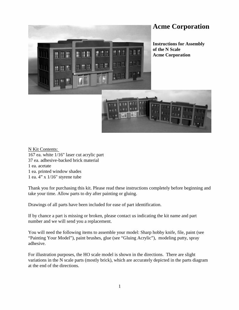
Acme Corporation
Instructions for Assemblyof the N ScaleAcme Corporation
N Kit Contents: 167 ea. white 1/16" laser cut acrylic part37 ea. adhesive-backed brick material1 ea. acetate1 ea. printed window shades1 ea. 4” x 1/16" styrene tube
Thank you for purchasing this kit. Please read these instructions completely before beginning andtake your time. Allow parts to dry after painting or gluing.
Drawings of all parts have been included for ease of part identification.
If by chance a part is missing or broken, please contact us indicating the kit name and partnumber and we will send you a replacement.
You will need the following items to assemble your model: Sharp hobby knife, file, paint (see“Painting Your Model”), paint brushes, glue (see “Gluing Acrylic”), modeling putty, sprayadhesive.
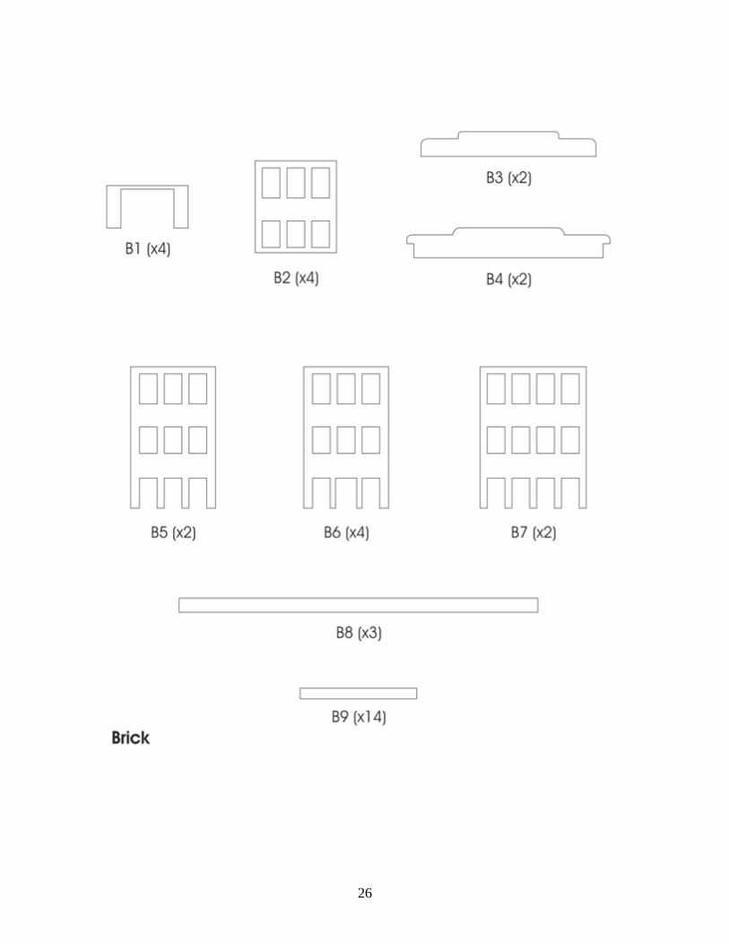
For illustration purposes, the HO scale model is shown in the directions. There are slightvariations in the N scale parts (mostly brick), which are accurately depicted in the parts diagramat the end of the directions.
2
3
About the Kit
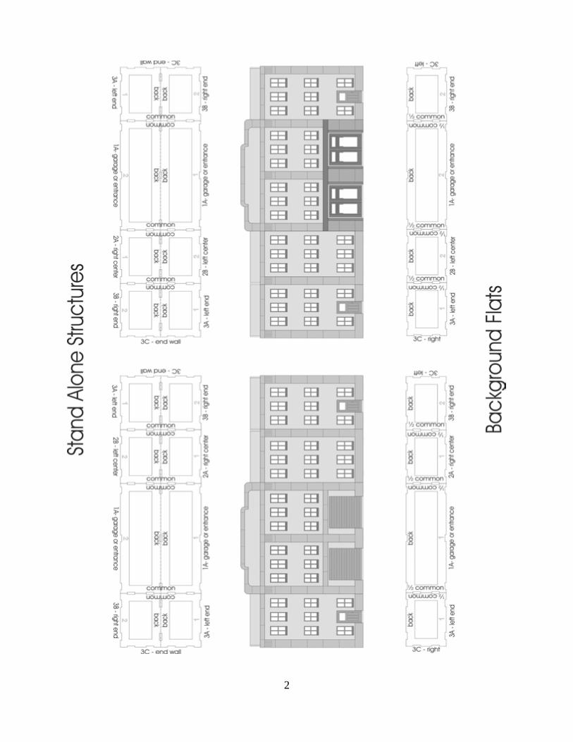
This building may be constructed as a single structure or two background flats. Instructions areincluded for both variations. Follow the directions in the appropriately marked section. Youmust choose ahead of time to create a stand alone structure or background flats and construct theunits accordingly. Later in the construction process, you will decide the configuration of the finalstructure(s). See page 2 for variations.
You may also choose to create your own custom structure with the 8 individual units used tomake the background flats. They may be rearranged to create buildings of different widths andconfigurations. Note that the Common walls are the same size as the end walls (3C) and can beswapped accordingly. If you wish to swap walls, this will need to be mapped out ahead of timeand implemented during construction.
For ease of part identification, we paint our model between steps to illustrate part placement. When building your model, follow the directions for painting at the appropriate point ofconstruction.
Gluing Acrylic
Always glue acrylic in a well-ventilated area, and read the glue manufacturer’s label forinstructions.
We recommend using Plastruct brand “Plastic Weld Solvent Cement” (PPC-2 or PPC-16) or“Bondine Solvent Cement”(Bond-2 or BOND-16). Plastruct sells a Solvent Syringe (HT-8 orHT-10) and various other solvent dispensers. Most hobby shops carry these products or they maybe ordered directly from Plastruct.
Acrylic must be glued together using a solvent that will melt the two edges and literally fusethem together. To do this, place the two pieces to be joined together and run a bead of solventdown the edge. Capillary action will suck the solvent into the joint and after several seconds thepieces will be fused. After only a few minutes the pieces will be strong enough to work with. Thebond will be completely dry within twenty-four hours using the above-mentioned products.
Solvent can be dispensed two ways. Typically the solvent comes in a small bottle with a brush inthe lid. The brush allows you to dispense a drop or two of solvent at a time. You may want touse a polyethylene bottle or syringe with a blunt needle dispenser. This allows larger amounts ofsolvent to be dispensed quickly and cleanly. Be sure the bottle you are using is approved for thesolvent you are using or you may melt through it. These may be purchased from CMR.
For this model, many parts will be adhered using super glue (CA), as the two surfaces to be gluedtogether will have paint on them. Follow the directions where noted.
4
Preparing Your Model for Painting
Lightly sand all parts to remove the raised edge created during the laser cutting process. In orderto hide any seams use “hobbyist putty” such as Green Squadron modeling putty. Do this in a wellventilated area. Apply the putty over the seams; allow to dry overnight. Once the putty has drieduse a sanding block to smooth. You may need to apply a second coat of putty and sand again.
Sometimes it is necessary to sand or file the tabs slightly in order to get them to seat themselvesinto the slots. This is due to slight variations in acrylic thickness. If the tabs are not fitting intothe slots you may need to file them back at an angle to fit properly.
Painting Your Model
For our building paint scheme, we used Krylon spray paints which are available in mosthardware stores. We also used “Polly Scale Acrylics” for details and weathering. These areavailable in most hobby shops.
Always test compatibility of your paint with the acrylic by painting and testing a small area first.Alcohol can cause acrylic to crack and “shatter”. Do not use alcohol to clean the parts or alcohol-based paints. If you apply washes to your building we recommend using a water-based wash.
If you plan to light your building’s interior, we recommend that you prime the building insideand out. This will prevent the walls from glowing. If you wish to weather or air brush yourbuilding, do so before installing the windows. We spray painted the building ruddy brown primer. The doors and windows were painted brown. The garage doors were painted gray. The sills and stone trim were painted concrete. Theentrance doors and awning were painted silver.
Window Glass
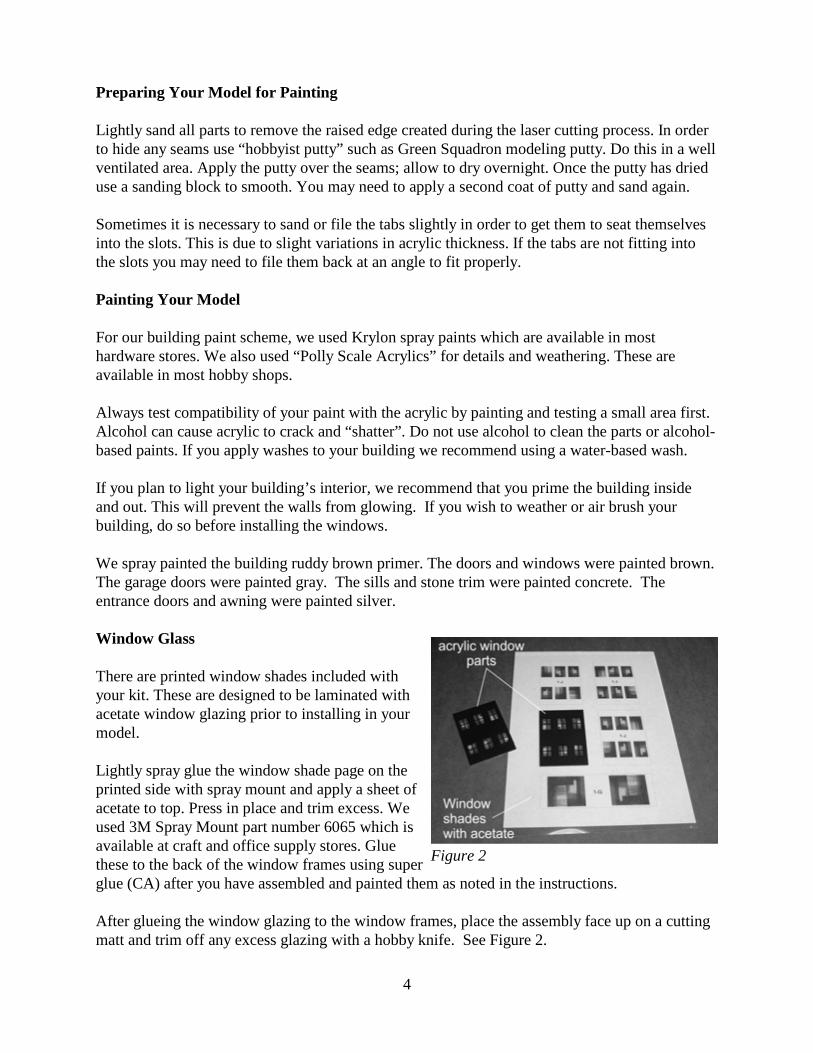
There are printed window shades included withyour kit. These are designed to be laminated withacetate window glazing prior to installing in yourmodel.
Lightly spray glue the window shade page on theprinted side with spray mount and apply a sheet ofacetate to top. Press in place and trim excess. Weused 3M Spray Mount part number 6065 which isavailable at craft and office supply stores. Gluethese to the back of the window frames using superglue (CA) after you have assembled and painted them as noted in the instructions.
After glueing the window glazing to the window frames, place the assembly face up on a cuttingmatt and trim off any excess glazing with a hobby knife. See Figure 2.
Figure 2
5
Large Center Unit: Construction for a stand alone unit
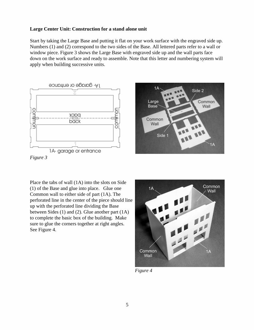
Start by taking the Large Base and putting it flat on your work surface with the engraved side up. Numbers (1) and (2) correspond to the two sides of the Base. All lettered parts refer to a wall orwindow piece. Figure 3 shows the Large Base with engraved side up and the wall parts facedown on the work surface and ready to assemble. Note that this letter and numbering system willapply when building successive units.
Place the tabs of wall (1A) into the slots on Side(1) of the Base and glue into place. Glue oneCommon wall to either side of part (1A). Theperforated line in the center of the piece should lineup with the perforated line dividing the Basebetween Sides (1) and (2). Glue another part (1A)to complete the basic box of the building. Makesure to glue the corners together at right angles. See Figure 4.
Figure 3
Figure 4
6
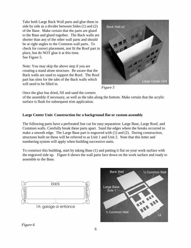
Take both Large Back Wall parts and glue them inside by side as a divider between Sides (1) and (2)of the Base. Make certain that the parts are gluedto the Base and glued together. The Back walls areshorter than any of the other wall parts and shouldbe at right angles to the Common wall parts. Tocheck for correct placement, test fit the Roof part inplace, but do NOT glue it at this time. See Figure 5.
Note: You may skip the above step if you arecreating a stand alone structure. Be aware that theBack walls are used to support the Roof. The Roofpart has slots for the tabs of the Back walls whichwill need to be filled in.
Once the glue has dried, fill and sand the corners of the assembly if necessary, as well as the tabs along the bottom. Make certain that the acrylicsurface is flush for subsequent trim application.
Large Center Unit: Construction for a background flat or custom assembly
The following parts have a perforated line cut for easy separation: Large Base, Large Roof, andCommon walls. Carefully break these parts apart. Sand the edges where the breaks occurred tomake a smooth edge. The Large Base part is engraved with (1) and (2). During construction,structures built on these will be referred to as Unit 1 and Unit 2. Note that this letter andnumbering system will apply when building successive units.
To construct this building, start by taking Base (1) and putting it flat on your work surface withthe engraved side up. Figure 6 shows the wall parts face down on the work surface and ready toassemble to the Base.
Figure 5
Figure 6
7
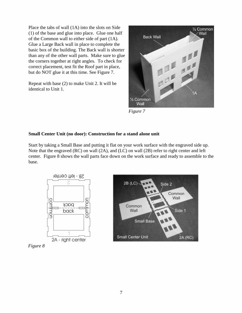
Place the tabs of wall (1A) into the slots on Side(1) of the base and glue into place. Glue one halfof the Common wall to either side of part (1A).Glue a Large Back wall in place to complete thebasic box of the building. The Back wall is shorterthan any of the other wall parts. Make sure to gluethe corners together at right angles. To check forcorrect placement, test fit the Roof part in place,but do NOT glue it at this time. See Figure 7.
Repeat with base (2) to make Unit 2. It will beidentical to Unit 1.
Small Center Unit (no door): Construction for a stand alone unit
Start by taking a Small Base and putting it flat on your work surface with the engraved side up.Note that the engraved (RC) on wall (2A), and (LC) on wall (2B) refer to right center and leftcenter. Figure 8 shows the wall parts face down on the work surface and ready to assemble to thebase.
Figure 7
Figure 8

8
Place the tabs of the right center wall (2A) into theslots on Side (1) of the Base and glue into place. Glue one Common wall to either side of part (2A).The perforated line in the center of the piece shouldline up with the perforated line dividing the Basebetween Sides (1) and (2). Glue the left center wall(2B) to Side (2) to complete the basic box of thebuilding. Make sure to glue the corners together atright angles. See Figure 9.
Take two Small Back walls and glue them in sideby side as a divider between Sides (1) and (2) ofthe Base. Make certain that the parts are glued tothe Base and glued together. The Back walls areshorter than any of the other wall parts and shouldbe at right angles to the Common wall parts. Tocheck for correct placement, test fit the Roof partin place, but do NOT glue it at this time. SeeFigure 10.
Note: You may skip the above step if you arecreating a stand alone structure.
Once the glue has dried, fill and sand the corners ofthe assembly if necessary, as well as the tabs alongthe bottom. Make certain that the acrylic surface isflush for subsequent trim application.
Figure 9
Figure 10
9
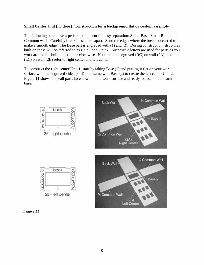
Small Center Unit (no door): Construction for a background flat or custom assembly
The following parts have a perforated line cut for easy separation: Small Base, Small Roof, andCommon walls. Carefully break these parts apart. Sand the edges where the breaks occurred tomake a smooth edge. The Base part is engraved with (1) and (2). During construction, structuresbuilt on these will be referred to as Unit 1 and Unit 2. Successive letters are used for parts as youwork around the building counter-clockwise. Note that the engraved (RC) on wall (2A), and(LC) on wall (2B) refer to right center and left center.
To construct the right center Unit 1, start by taking Base (1) and putting it flat on your worksurface with the engraved side up. Do the same with Base (2) to create the left center Unit 2. Figure 11 shows the wall parts face down on the work surface and ready to assemble to eachbase.
Figure 11
10
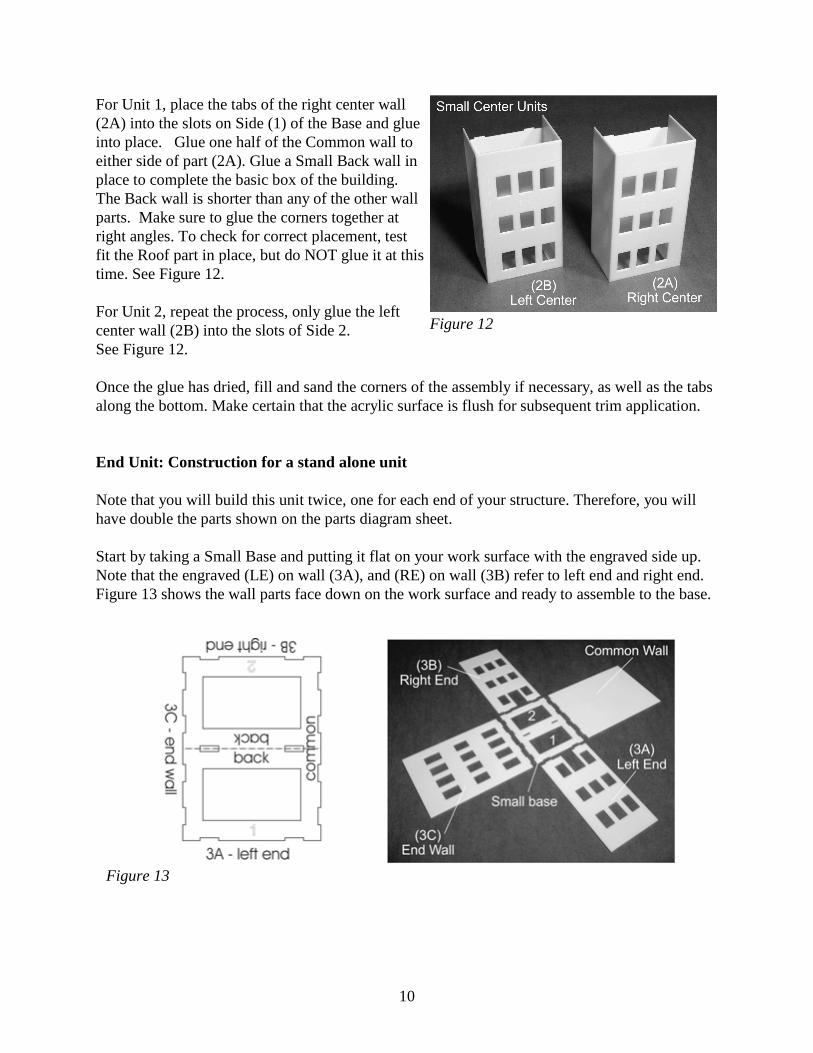
For Unit 1, place the tabs of the right center wall(2A) into the slots on Side (1) of the Base and glueinto place. Glue one half of the Common wall toeither side of part (2A). Glue a Small Back wall inplace to complete the basic box of the building.The Back wall is shorter than any of the other wallparts. Make sure to glue the corners together atright angles. To check for correct placement, testfit the Roof part in place, but do NOT glue it at thistime. See Figure 12.
For Unit 2, repeat the process, only glue the leftcenter wall (2B) into the slots of Side 2. See Figure 12.
Once the glue has dried, fill and sand the corners of the assembly if necessary, as well as the tabsalong the bottom. Make certain that the acrylic surface is flush for subsequent trim application.
End Unit: Construction for a stand alone unit
Note that you will build this unit twice, one for each end of your structure. Therefore, you willhave double the parts shown on the parts diagram sheet.
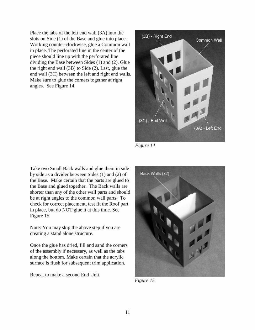
Start by taking a Small Base and putting it flat on your work surface with the engraved side up.Note that the engraved (LE) on wall (3A), and (RE) on wall (3B) refer to left end and right end. Figure 13 shows the wall parts face down on the work surface and ready to assemble to the base.
Figure 12
Figure 13
11
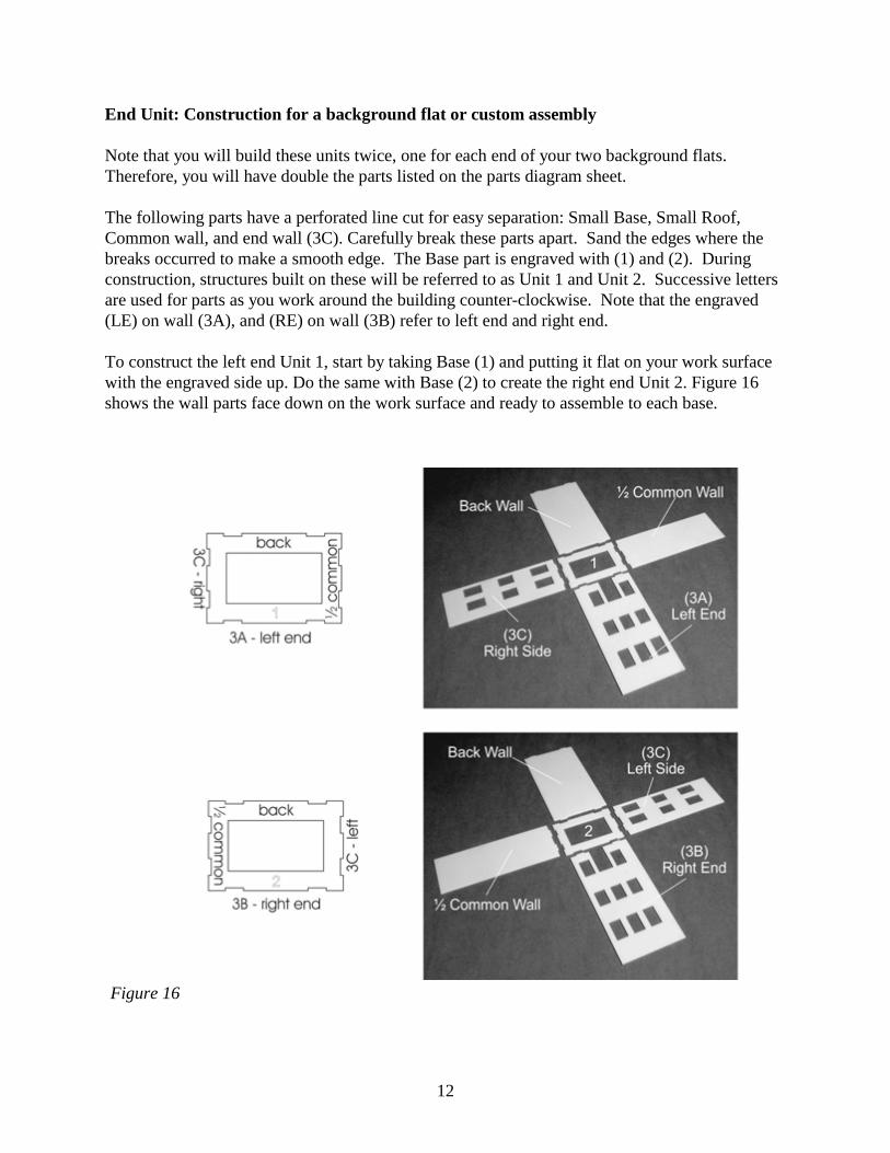
Place the tabs of the left end wall (3A) into theslots on Side (1) of the Base and glue into place.Working counter-clockwise, glue a Common wallin place. The perforated line in the center of thepiece should line up with the perforated linedividing the Base between Sides (1) and (2). Gluethe right end wall (3B) to Side (2). Last, glue theend wall (3C) between the left and right end walls. Make sure to glue the corners together at rightangles. See Figure 14.
Take two Small Back walls and glue them in sideby side as a divider between Sides (1) and (2) ofthe Base. Make certain that the parts are glued tothe Base and glued together. The Back walls areshorter than any of the other wall parts and shouldbe at right angles to the common wall parts. Tocheck for correct placement, test fit the Roof partin place, but do NOT glue it at this time. SeeFigure 15.
Note: You may skip the above step if you arecreating a stand alone structure.
Once the glue has dried, fill and sand the cornersof the assembly if necessary, as well as the tabsalong the bottom. Make certain that the acrylicsurface is flush for subsequent trim application.
Repeat to make a second End Unit.
Figure 14
Figure 15
12
End Unit: Construction for a background flat or custom assembly
Note that you will build these units twice, one for each end of your two background flats.Therefore, you will have double the parts listed on the parts diagram sheet.
The following parts have a perforated line cut for easy separation: Small Base, Small Roof,Common wall, and end wall (3C). Carefully break these parts apart. Sand the edges where thebreaks occurred to make a smooth edge. The Base part is engraved with (1) and (2). Duringconstruction, structures built on these will be referred to as Unit 1 and Unit 2. Successive lettersare used for parts as you work around the building counter-clockwise. Note that the engraved(LE) on wall (3A), and (RE) on wall (3B) refer to left end and right end.
To construct the left end Unit 1, start by taking Base (1) and putting it flat on your work surfacewith the engraved side up. Do the same with Base (2) to create the right end Unit 2. Figure 16shows the wall parts face down on the work surface and ready to assemble to each base.
Figure 16
13
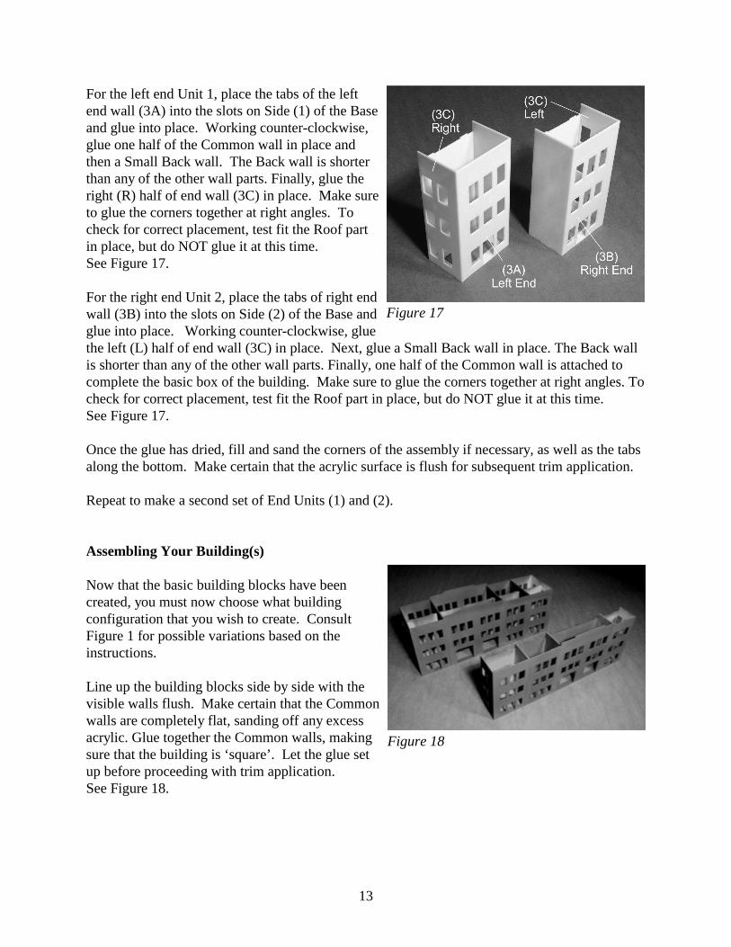
For the left end Unit 1, place the tabs of the leftend wall (3A) into the slots on Side (1) of the Baseand glue into place. Working counter-clockwise,glue one half of the Common wall in place andthen a Small Back wall. The Back wall is shorterthan any of the other wall parts. Finally, glue theright (R) half of end wall (3C) in place. Make sureto glue the corners together at right angles. Tocheck for correct placement, test fit the Roof partin place, but do NOT glue it at this time. See Figure 17.
For the right end Unit 2, place the tabs of right endwall (3B) into the slots on Side (2) of the Base andglue into place. Working counter-clockwise, gluethe left (L) half of end wall (3C) in place. Next, glue a Small Back wall in place. The Back wallis shorter than any of the other wall parts. Finally, one half of the Common wall is attached tocomplete the basic box of the building. Make sure to glue the corners together at right angles. Tocheck for correct placement, test fit the Roof part in place, but do NOT glue it at this time. See Figure 17.
Once the glue has dried, fill and sand the corners of the assembly if necessary, as well as the tabsalong the bottom. Make certain that the acrylic surface is flush for subsequent trim application.
Repeat to make a second set of End Units (1) and (2).
Assembling Your Building(s)
Now that the basic building blocks have beencreated, you must now choose what buildingconfiguration that you wish to create. ConsultFigure 1 for possible variations based on theinstructions.
Line up the building blocks side by side with thevisible walls flush. Make certain that the Commonwalls are completely flat, sanding off any excessacrylic. Glue together the Common walls, makingsure that the building is ‘square’. Let the glue setup before proceeding with trim application. See Figure 18.
Figure 17
Figure 18
14
Applying the Trim
Note: Alignment of the trim is crucial, as the brick parts will need to be glued inside the trimborders in the next step. Engraved guide lines for the trim are on the wall parts. Despite theinclusion of guide lines, we do recommend that you test fit the trim around the brick (withoutaffixing in place) so you know exactly where the trim pieces should be glued.
Trim Large Center Unit
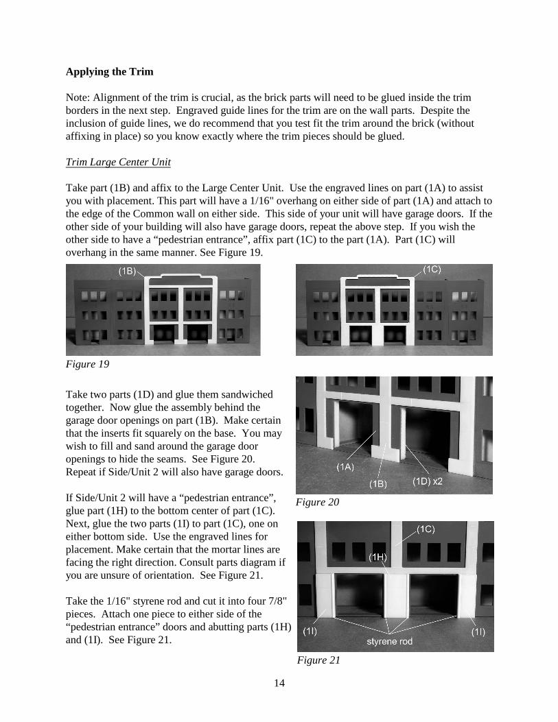
Take part (1B) and affix to the Large Center Unit. Use the engraved lines on part (1A) to assistyou with placement. This part will have a 1/16" overhang on either side of part (1A) and attach tothe edge of the Common wall on either side. This side of your unit will have garage doors. If theother side of your building will also have garage doors, repeat the above step. If you wish theother side to have a “pedestrian entrance”, affix part (1C) to the part (1A). Part (1C) willoverhang in the same manner. See Figure 19.
Take two parts (1D) and glue them sandwichedtogether. Now glue the assembly behind thegarage door openings on part (1B). Make certainthat the inserts fit squarely on the base. You maywish to fill and sand around the garage dooropenings to hide the seams. See Figure 20. Repeat if Side/Unit 2 will also have garage doors.
If Side/Unit 2 will have a “pedestrian entrance”,glue part (1H) to the bottom center of part (1C). Next, glue the two parts (1I) to part (1C), one oneither bottom side. Use the engraved lines forplacement. Make certain that the mortar lines arefacing the right direction. Consult parts diagram ifyou are unsure of orientation. See Figure 21.
Take the 1/16" styrene rod and cut it into four 7/8"pieces. Attach one piece to either side of the“pedestrian entrance” doors and abutting parts (1H)and (1I). See Figure 21.
Figure 20
Figure 19
Figure 21
15
Trim Small Center Unit
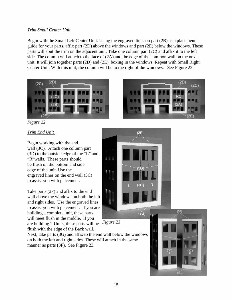
Begin with the Small Left Center Unit. Using the engraved lines on part (2B) as a placementguide for your parts, affix part (2D) above the windows and part (2E) below the windows. Theseparts will abut the trim on the adjacent unit. Take one column part (2C) and affix it to the leftside. The column will attach to the face of (2A) and the edge of the common wall on the nextunit. It will join together parts (2D) and (2E), boxing in the windows. Repeat with Small RightCenter Unit. With this unit, the column will be to the right of the windows. See Figure 22.
Trim End Unit
Begin working with the end wall (3C). Attach one column part (3D) to the outside edge of the “L” and“R”walls. These parts shouldbe flush on the bottom and sideedge of the unit. Use the engraved lines on the end wall (3C) to assist you with placement.
Take parts (3F) and affix to the endwall above the windows on both the leftand right sides. Use the engraved linesto assist you with placement. If you arebuilding a complete unit, these partswill meet flush in the middle. If youare building 2 Units, these parts will beflush with the edge of the Back wall. Next, take parts (3G) and affix to the end wall below the windowson both the left and right sides. These will attach in the samemanner as parts (3F). See Figure 23.
Figure 22
Figure 23
16
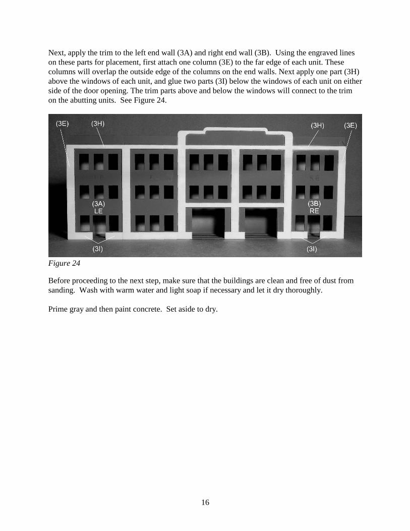
Next, apply the trim to the left end wall (3A) and right end wall (3B). Using the engraved lineson these parts for placement, first attach one column (3E) to the far edge of each unit. Thesecolumns will overlap the outside edge of the columns on the end walls. Next apply one part (3H)above the windows of each unit, and glue two parts (3I) below the windows of each unit on eitherside of the door opening. The trim parts above and below the windows will connect to the trimon the abutting units. See Figure 24.
Before proceeding to the next step, make sure that the buildings are clean and free of dust fromsanding. Wash with warm water and light soap if necessary and let it dry thoroughly.
Prime gray and then paint concrete. Set aside to dry.
Figure 24
17
Applying the Brick
The brick is pre-cut to fit each part of the building and will require little, if any, trimming. Thereis crack and peel adhesive on the back which will make for easy application. Simply remove thepaper backing and press in place. Please note, however, that once in place, these pieces may notbe repositioned. The adhesive makes strong contact with the wall surface, so apply withouthesitation.
When glueing any parts to your building after the brick application (windows or sills), it isimportant to use super glue (CA) or craft glue. This is because the liquid glue can get behind thebrick sheet and cause the adhesive to release.
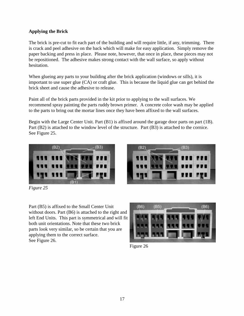
Paint all of the brick parts provided in the kit prior to applying to the wall surfaces. Werecommend spray painting the parts ruddy brown primer. A concrete color wash may be appliedto the parts to bring out the mortar lines once they have been affixed to the wall surfaces. Begin with the Large Center Unit. Part (B1) is affixed around the garage door parts on part (1B). Part (B2) is attached to the window level of the structure. Part (B3) is attached to the cornice.See Figure 25.
Part (B5) is affixed to the Small Center Unitwithout doors. Part (B6) is attached to the right andleft End Units. This part is symmetrical and will fitboth unit orientations. Note that these two brickparts look very similar, so be certain that you areapplying them to the correct surface.See Figure 26.
Figure 25
Figure 26
18
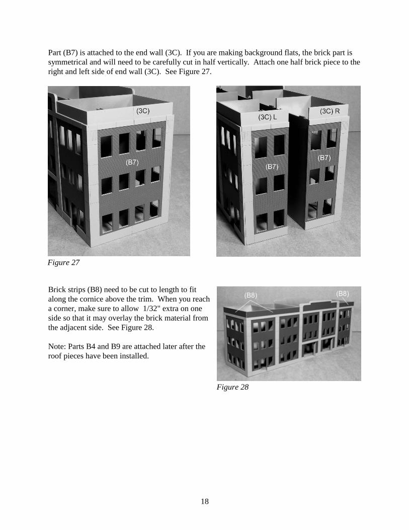
Part (B7) is attached to the end wall (3C). If you are making background flats, the brick part issymmetrical and will need to be carefully cut in half vertically. Attach one half brick piece to theright and left side of end wall (3C). See Figure 27.
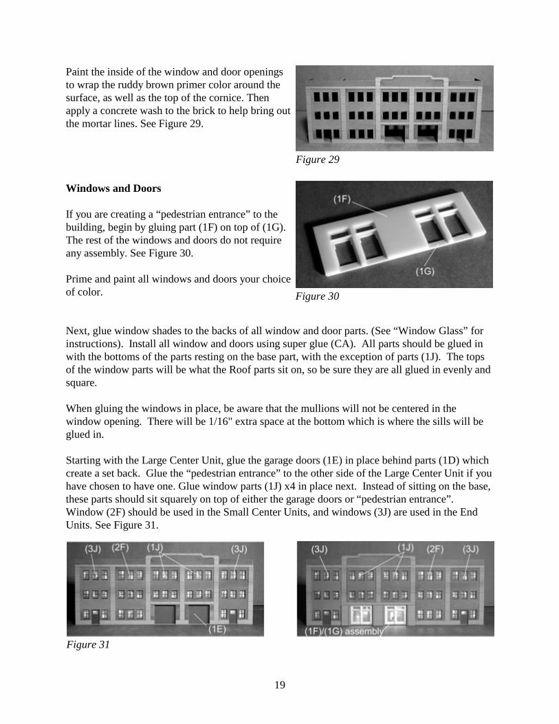
Brick strips (B8) need to be cut to length to fitalong the cornice above the trim. When you reacha corner, make sure to allow 1/32" extra on oneside so that it may overlay the brick material fromthe adjacent side. See Figure 28.
Note: Parts B4 and B9 are attached later after theroof pieces have been installed.
Figure 27
Figure 28
19
Paint the inside of the window and door openingsto wrap the ruddy brown primer color around thesurface, as well as the top of the cornice. Thenapply a concrete wash to the brick to help bring outthe mortar lines. See Figure 29.
Windows and Doors
If you are creating a “pedestrian entrance” to thebuilding, begin by gluing part (1F) on top of (1G). The rest of the windows and doors do not requireany assembly. See Figure 30.
Prime and paint all windows and doors your choiceof color.
Next, glue window shades to the backs of all window and door parts. (See “Window Glass” forinstructions). Install all window and doors using super glue (CA). All parts should be glued inwith the bottoms of the parts resting on the base part, with the exception of parts (1J). The topsof the window parts will be what the Roof parts sit on, so be sure they are all glued in evenly andsquare.
When gluing the windows in place, be aware that the mullions will not be centered in thewindow opening. There will be 1/16" extra space at the bottom which is where the sills will beglued in.
Starting with the Large Center Unit, glue the garage doors (1E) in place behind parts (1D) whichcreate a set back. Glue the “pedestrian entrance” to the other side of the Large Center Unit if youhave chosen to have one. Glue window parts (1J) x4 in place next. Instead of sitting on the base,these parts should sit squarely on top of either the garage doors or “pedestrian entrance”.Window (2F) should be used in the Small Center Units, and windows (3J) are used in the EndUnits. See Figure 31.
Figure 29
Figure 30
Figure 31
20
Last, part (3K)-L is affixed behind the left side ofthe end wall, and part (3K)-R is glued behind theright side of the end wall. See Figure 32.
Final Assembly
Remove the sills from the partssheet. Make sure to sand off thetabs, as the sills are to fit squarelyagainst the window parts. Primeand paint. When dry, glue inplace using super glue (CA). See Figure 33.
If you have a “pedestrian entrance”, take the threeawning parts (1K) and sandwich them together,gluing them flush all the way around. You maywish to fill and sand the seam. Paint silver andglue to part (1C) above the door using CA (superglue). See Figure 33.
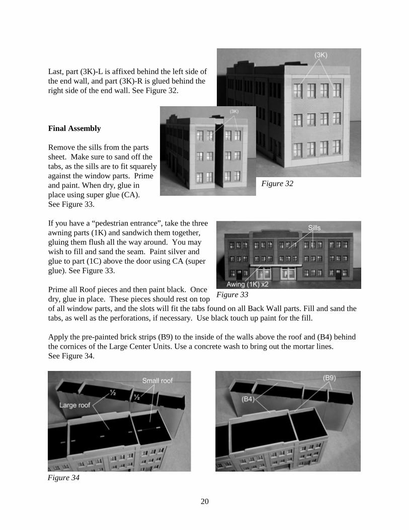
Prime all Roof pieces and then paint black. Oncedry, glue in place. These pieces should rest on topof all window parts, and the slots will fit the tabs found on all Back Wall parts. Fill and sand thetabs, as well as the perforations, if necessary. Use black touch up paint for the fill.
Apply the pre-painted brick strips (B9) to the inside of the walls above the roof and (B4) behindthe cornices of the Large Center Units. Use a concrete wash to bring out the mortar lines.See Figure 34.
Figure 35 Figure 32
Figure 33
Figure 34
21
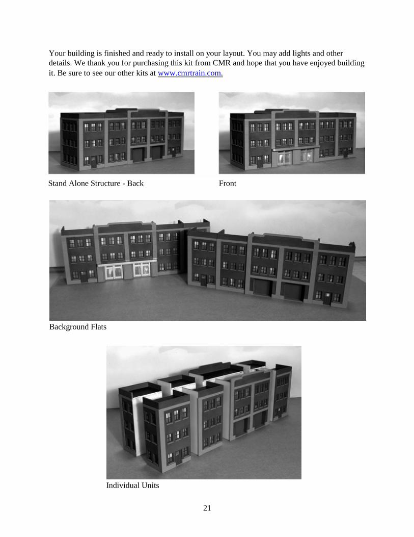
Your building is finished and ready to install on your layout. You may add lights and otherdetails. We thank you for purchasing this kit from CMR and hope that you have enjoyed buildingit. Be sure to see our other kits at www.cmrtrain.com.
Stand Alone Structure - Back Front
Individual Units
Background Flats
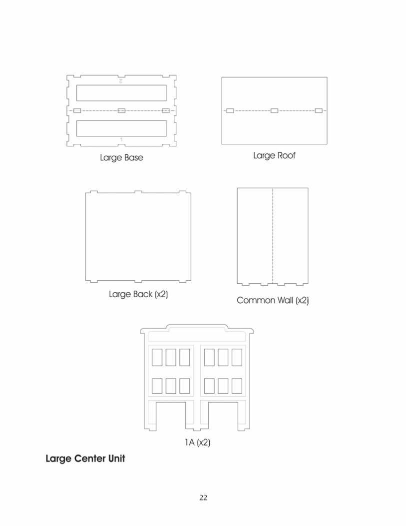
22
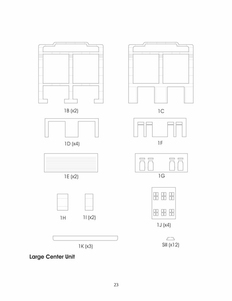
23
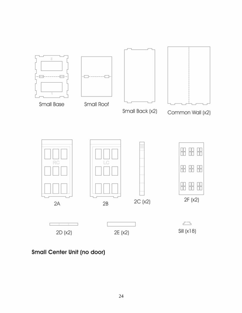
24
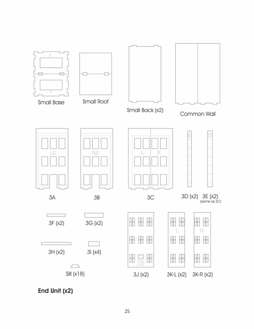
25
26