Embed Size (px)
Citation preview

ACL Series PumpOperation and Maintenance ManualAir Driven, High Pressure Liquid Pump
Catalog: 02-9240ME February2013
2Parker Autoclave EngineersInstrumentation Products DivisionErie, PA USAwww.autoclave.com | Cat. 02-9240ME
Model #
Serial #
Drawing #
Order #
Mfg. Date
Table of ConTenTs page
1.0 Introduction .......................................................................................................... 3
2.0 Meaning of Safety Words ...................................................................................... 3
3.0 ProductSpecification ............................................................................................ 3
4.0 Unpacking ............................................................................................................. 3
5.0 Tools ..................................................................................................................... 3
6.0 Installation ............................................................................................................ 3
6.1 Compressed Air Supply ....................................................................................... 4
6.2 Liquid Section ....................................................................................................... 4
7.0 Pump Start-Up ...................................................................................................... 5
8.0 Process Media ...................................................................................................... 5
9.0 Pump Functionality ............................................................................................... 6
10.0 Suggested Maintenance ....................................................................................... 6
11.0 Trouble Shooting-Pneumatic Section .................................................................... 7
12.0 Trouble Shooting-High Pressure Liquid Section ................................................... 7
13.0 Service .................................................................................................................. 8

3Parker Autoclave EngineersInstrumentation Products DivisionErie, PA USAwww.autoclave.com | Cat. 02-9240ME
Section 1.0Introduction
The Parker Autoclave Engineers pump discussed in this manual is operated using compressed air up to 150 psi (10 bar). Parker Autoclave Engineers ACL Series pumps are used for pumping oil, water and oil/water mixtures. Special seals are also available for chemical service. Please contact Parker Autoclave Engineers to discuss availability of special seals. The pump operates using a pressure ratio of the air piston surface area to the liquid plunger surface area.
(Output liquid pressure = actual pump pressure ratio x input air pressure). Refer to the product literature for each pump model's actual air pressure ratio.
Section 2.0Meaning of Safety Words
A safety related message is identified by a safety alert symbol and a signal word to indicate the level of riskinvolved with a particular hazard. The definitions of the three signal words are as follows:
indicates a potentially hazardous situation which, if not avoided, could result in death or serious injury.
indicates a potentially hazardous situation which, if not avoided, may result
in minor or moderate injury.
Special notes intended to bring attention to procedures that must be followed to ensure proper installation and performance will be placed in a box labeled NOTICE.
Section 3.0Product Specification
See assembly drawing for product specifications:
- Pump Geometry- Pump Materials of Construction- Maximum Allowable Working Pressure- Maximum Working Temperature- Pressure Ratio- Displacement- Repair Kit Part Numbers- Torque Information- Weights
WARNING!
CAUTION!
Section 4.0Unpacking
The pump has been assembled and pressure tested at Parker Autoclave Engineers and is ready to be put into service. The shipping carton should be opened and the contents carefully examined upon receipt from the carrier. Make sure there is no obvious damage to the contents. DO NOT use the equipment if any damage is evident. If damage has occurred, file a claim with the shipper before contacting Parker Autoclave Engineers Service Department.
Examine all material within the container and check against the packing list to be sure all items are accounted for and are not damaged. Verify that the equipment model number supplied agrees with what was ordered.
Section 5.0Tools
At minimum, the tools required for installation of the pump in-clude a torque wrench, an open end wrench adapter (crows foot adapter) and an open end adjustable wrench.
Refer to the Tools, Maintenance and Installation Manual provided with the Data Book for information on torque wrenches and torque values for Parker Autoclave Engineers tubing and fittings.
Section 6.0Installation
Please read this manual in its entirety before attempting to operate an Parker Autoclave Engineers high
pressure liquid pump
! WARNING
Installation to be performed only by properly trained individuals.
! WARNING
Proper protective safety gear must be worn while installing and operating the pump.
! WARNING
4Parker Autoclave EngineersInstrumentation Products DivisionErie, PA USAwww.autoclave.com | Cat. 02-9240ME
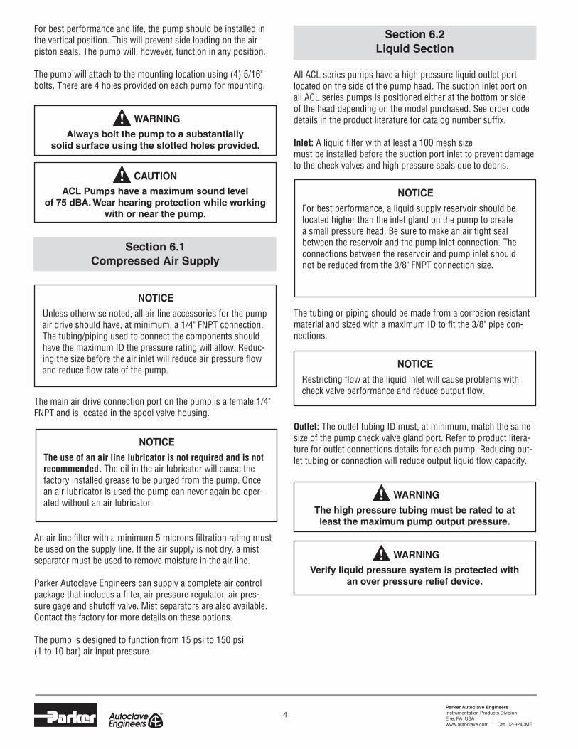
For best performance and life, the pump should be installed in the vertical position. This will prevent side loading on the air piston seals. The pump will, however, function in any position.
The pump will attach to the mounting location using (4) 5/16" bolts. There are 4 holes provided on each pump for mounting.
Section 6.1Compressed Air Supply
The main air drive connection port on the pump is a female 1/4" FNPT and is located in the spool valve housing.
An air line filter with a minimum 5 microns filtration rating must be used on the supply line. If the air supply is not dry, a mist separator must be used to remove moisture in the air line.
Parker Autoclave Engineers can supply a complete air control package that includes a filter, air pressure regulator, air pres-sure gage and shutoff valve. Mist separators are also available. Contact the factory for more details on these options.
The pump is designed to function from 15 psi to 150 psi (1 to 10 bar) air input pressure.
Always bolt the pump to a substantially solid surface using the slotted holes provided.
! WARNING
ACL Pumps have a maximum sound level of 75 dBA. Wear hearing protection while working
with or near the pump.
! CAUTION
Unless otherwise noted, all air line accessories for the pump air drive should have, at minimum, a 1/4" FNPT connection. The tubing/piping used to connect the components should have the maximum ID the pressure rating will allow. Reduc-ing the size before the air inlet will reduce air pressure flow and reduce flow rate of the pump.
NOTICE
The use of an air line lubricator is not required and is not recommended. The oil in the air lubricator will cause the factory installed grease to be purged from the pump. Once an air lubricator is used the pump can never again be oper-ated without an air lubricator.
NOTICE
Section 6.2Liquid Section
All ACL series pumps have a high pressure liquid outlet port located on the side of the pump head. The suction inlet port on all ACL series pumps is positioned either at the bottom or side of the head depending on the model purchased. See order code details in the product literature for catalog number suffix.
Inlet: A liquid filter with at least a 100 mesh size must be installed before the suction port inlet to prevent damage to the check valves and high pressure seals due to debris.
The tubing or piping should be made from a corrosion resistant material and sized with a maximum ID to fit the 3/8" pipe con-nections.
Outlet: The outlet tubing ID must, at minimum, match the same size of the pump check valve gland port. Refer to product litera-ture for outlet connections details for each pump. Reducing out-let tubing or connection will reduce output liquid flow capacity.
For best performance, a liquid supply reservoir should be located higher than the inlet gland on the pump to create a small pressure head. Be sure to make an air tight seal between the reservoir and the pump inlet connection. The connections between the reservoir and pump inlet should not be reduced from the 3/8" FNPT connection size.
NOTICE
Restricting flow at the liquid inlet will cause problems with check valve performance and reduce output flow.
NOTICE
The high pressure tubing must be rated to at least the maximum pump output pressure.
! WARNING
Verify liquid pressure system is protected with an over pressure relief device.
! WARNING
5Parker Autoclave EngineersInstrumentation Products DivisionErie, PA USAwww.autoclave.com | Cat. 02-9240ME
Increase the air pressure using the air pressure regulator until you achieve your desired output liquid pressure. At this point the pump will stall. You can calculate the output pressure by multiplying the input air supply by the actual pressure ratio of the pump. The pump will automatically restart if there is a drop in downstream high pressure.
Section 8.0Process Media
Parker Autoclave Engineers pumps discussed in this manual are used for pumping oil, water and oil/water mixtures. Special seals are also available for chemical service. Please contact Parker Autoclave Engineers to discuss availability of special seals.
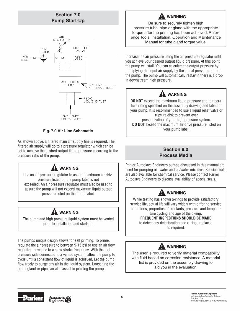
Section 7.0Pump Start-Up
Fig. 7.0 Air Line Schematic
As shown above, a filtered main air supply line is required. The filtered air supply will go to a pressure regulator which can be set to achieve the desired output liquid pressure according to the pressure ratio of the pump.
The pumps unique design allows for self priming. To prime, regulate the air pressure to between 5-15 psi or use an air flow regulator to reduce to a slow stroke frequency. With the high pressure side connected to a vented system, allow the pump to cycle until a consistent flow of liquid is achieved. Let the pump flow freely to purge any air in the liquid system. Loosening the outlet gland or pipe can also assist in priming the pump.
Use an air pressure regulator to assure maximum air drive pressure listed on the pump label is not
exceeded. An air pressure regulator must also be used to assure the pump will not exceed maximum liquid output
pressure listed on the pump label.
! WARNING
The pump and high pressure liquid system must be vented prior to installation and start-up.
! WARNING
DO NOT exceed the maximum liquid pressure and tempera-ture rating specified on the assembly drawing and label for your pump. It is recommended to use a liquid relief valve or
rupture disk to prevent over pressurization of your high pressure system.
DO NOT exceed the maximum air drive pressure listed on your pump label.
! WARNING
Be sure to securely tighten high pressure tube, pipe or gland with the appropriate
torque after the priming has been achieved. Refer-ence Tools, Installation, Operation and Maintenance
Manual for tube gland torque value.
! WARNING
While testing has shown o-rings to provide satisfactory service life, actual life will vary widely with differing service conditions, properties of reactants, pressure and tempera-
ture cycling and age of the o-ring. FREQUENT INSPECTIONS SHOULD BE MADE
to detect any deterioration and o-rings replaced as required.
! WARNING
The user is required to verify material compatibility withfluidbasedoncorrosionresistance.Amaterial
list is provided on the assembly drawing to aid you in the evaluation.
! WARNING
6Parker Autoclave EngineersInstrumentation Products DivisionErie, PA USAwww.autoclave.com | Cat. 02-9240ME
Pumps are not designed to run for long periods of time without liquid process media. Short, dry pumping cycles should not be a cause for concern. However, pumps are built using lubricant in the seal areas and pumping without fluid will wear away lubricant and compromise the seal.
The operating temperatures of the pump are between 0°F to 140°F (18°F to 60°F).
Section 9.0Pump Functionality
When the pump is installed, regulated air is connected to the spool housing at the 1/4" FNPT pump inlet.
1) Regulated inlet air pressure enters spool housing and moves spool to the left directing air into large pressure tube to the bottom end cap pushing the air piston and liquid plunger upward.
2) The upward movement causes a suction of liquid into the high pressure pump head while inlet check valve is open and outlet check valve is closed.
3) The air piston continues to move up until it hits the pilot valve assembly in the top end cap.
4) The top pilot valve opens allowing max system air pressure to shift the spool valve so that it now directs air drive pressure through the top end cap and pushes the air piston and liquid plunger downward.
5) The plunger action moving down compresses the fluid on the high pressure pump head while the inlet check valve is closed and outlet check valve is open.
6) While the air drive pressure is acting on top of the piston, the bottom area of the piston is vented through the exhaust muffler.
7) Piston continues to move down until it hits the pilot valve assembly in the bottom end cap.
8) The bottom pilot opens which vents maximum system air pressure from the large diameter side of the spool.
9) This causes spool to move to the left, while air is vented from the top end of the air cylinder through the exhaust muffler.
10) The entire process starts again at step one until the maximum outlet hydraulic pressure in reached based on the pressure ratio of the pump.
seCTion 10.0 Suggested Maintenance
A. Before each pump use, a quick inspection should be per-formed to insure there are no loose bolts, nuts, set screws or check valve glands. Tighten any lose bolts and fittings according to the torque values listed on the pump assembly drawing. A visual inspection should also be made before each use and at startup to make sure there is no evidence of fluid leaks from isolation chamber drain ports, check valves connections and muffler. If liquid mists out of the muffler for more than 5 strokes, it is time to replace your hydraulic high pressure seals. Refer to the troubleshooting guide for solu-tions to these fluid leaks.
B. The maintenance schedule of the pump depends on the frequency of use, cleanliness of media, type of media, cycle rates, output pressures, cleanliness of air or any other condi-tions that may be damaging to seal integrity. Once a clear pattern develops of how long a pump is in service before pump performance declines, it is recommended to perform maintenance in advance of this time frame. At minimum, perform maintenance on the pump once a year as described below.
Maintenance would include: • Re-lubrication or replacement of spool valve o-ring • Re-lubrication or replacement of air drive seals • Re-lubrication or replacement of pilot valve o-rings and gaskets • Replace check valve components • Replace high pressure hydraulic seals
C. Maintenance instructions are supplied with appropriate rebuild kits. Kit part numbers are listed on the assembly drawing.
All pumps must be inspected periodically in order to assure proper and safe operating condition.
Failure to inspect pump can result in serious and catastrophic harm to personnel and the surrounding facility.
! WARNING
Before attempting to disassemble the pump or loosen fittings in a pressure system, be sure that liquid
pressure has been totally vented.
! WARNING
7Parker Autoclave EngineersInstrumentation Products DivisionErie, PA USAwww.autoclave.com | Cat. 02-9240ME
Section 11.0Trouble Shooting - Pneumatic Section
Problem: Pump will not operate with low air pressure.Cause:
Excessive friction of o-rings on the spool valve has increased the pressure required to move spool.
Solution: Replace and lubricate the o-rings on spool
Problem: Pump can only be actuated at high air pressure.
Cause: a) Air is leaking through the piston guide bushing in the top end cap.
b) Air is leaking through the o-rings between the top end cap and air cylinder.
Solution: a) Replace and lubricate o-rings on upper plunger and between bushing and top cap.
b) Replace and lubricate o-ring on lip of top end cap.
Problem: Pump will not run and air escaped through the exhaust muffler.
Cause: a) Spool valve o-rings are leaking.
b) Spool sleeve o-rings are leaking.
c) Outside o-ring(s) on air piston(s) is leaking.
d) Seal between air piston and liquid plunger is leaking.
Solution: a) Replace and lubricate spool valve o-rings.
b) Replace and lubricate sleeve o-rings.
c) Replace and lubricate air piston o-ring(s).
d) Add Loctite 2760 thread locker with sealant on plunger threads.
Problem: Pump will not run and air escapes through the small hole in the spool valve housing.
Cause: Spool valve sleeve o-rings are leaking.
Before attempting to perform maintenance on the pump, assure that air supply pressure is shut off
and vented from the pump.
! WARNINGSolution: Replace and lubricate spool valve o-rings.
Problem: Pump will not run and air escapes through the pilot valve vent in the bottom end cap.
Cause: Pilot valve gasket or o-ring is not sealing in the bottom cap.
Solution: Replace and lubricate pilot valve gasket and o-ring. If necessary, also replace the tappet rod.
Problem: Pump operates at a high frequency and short strokes.
Cause: The top or bottom pilot valves are defective.
Solution: Replace and lubricate both pilot valve gaskets and o-rings. If necessary also replace the tappet rods.
Problem: Pump functions slowly or doesn't operate at all.
Cause: a) Condensation from air supply is freezing the spool valve.
b) Air muffler is clogged.
Solution: a) Stop pump for a short period and replace or add a mist separator in the air line.
b) Clean or replace air muffler.
Section 12.0Trouble Shooting - High Pressure
Liquid Section
Problem: Pump does not produce liquid flow, operates irregularly or does not maintain pressure.
Cause: a) Air in the hydraulic system. b) Suction line excessively long.
c) Suction tubing sized too small.
d) Failure of one of the check valves.
e) Liquid inlet filter is blocked.
f) High pressure seal excessively worn.
g) Supply liquid pressure head too low.
h) Air pressure rod seal assembly excessively worn.
Solution: a) Check inlet suction line and connections for leaks and allow pump to flow freely downstream so as to remove any air.
b) Shorten liquid supply line.
c) Increase tubing ID size between reservoir and pump inlet.
d) Clean or replace both inlet and outlet check valve assemblies.
e) Clean or replace liquid inlet filter.
f) Replace high pressure seal assembly.
g) Raise liquid reservoir to higher location until pump is fully primed. h) Replace air pressure rod seal.
Problem: Fluid escapes through the air exhaust (non- isolation chamber version only).
Cause: High pressure seal is leaking.
Solution: a) Clean fluid from air section.
b) Replace and lubricate o-rings as necessary in the air section.
c) Replace high pressure seal.
Section 13 .0Service
Contact Parker Autoclave Engineers for service. Pumps can be sent directly to Parker Autoclave Engineers for service. Pumps returned for service should be accompanied with the model number, serial number, manufacture date and problems you are experiencing.
For service information: 814-860-5729
! WARNINGUse only originally specified parts when installing or
maintaining high-pressure equipment and follow all Parker Autoclave Engineers maintenance and
assembly procedures. Do not use any parts from other equipment to make repairs or modifications. Contact Parker
Autoclave Engineers with any questions or if sufficient information to complete the instal-
lation, maintenance and operation of the equipment has not been included.
02-9240ME February2013© 2013 Parker Hannifin Corporation | Autoclave Engineers is a registered trademark of the Parker Hannifin Corporation
Parker Hannifin Manufacturing Ltd. Instrumentation Products Division, Europe Industrial Estate WhitemillWexford, Republic of IrelandPH: 353 53 914 1566FAX: 353 53 914 1582
Instrumentation Products DivisionAutoclave Engineers Operation8325 Hessinger DriveErie, Pennsylvania 16509-4679 USAPH: 814-860-5700 FAX: 814-860-5811www.autoclave.com
WARNINGFAILURE, IMPROPER SELECTION OR IMPROPER USE OF THE PRODUCTS AND/OR SYSTEMS DESCRIBED HEREIN OR RELATED ITEMS CAN CAUSE DEATH, PERSONAL INJURY AND PROPERTY DAMAGE.This document and other information from Parker Hannifin Corporation, its subsidiaries and authorized distributors provide product and/or system options for further investigation by users having technical expertise. It is important that you analyze all aspects of your application and review the information concerning the product or system in the current product catalog. Due to the variety of operating conditions and applications for these products or systems, the user, through its own analysis and testing, is solely responsible for making the final selection of the products and systems and assuring that all performance, safety and warning requirements of the application are met. The products described herein, including without limitation, product features, specifications, designs, availability and pricing, are subject to change by Parker Hannifin Corporation and its subsidiaries at any time without notice.
Offer of SaleThe items described in this document are available for sale by Parker Hannifin Corporation, its subsidiaries or its authorized distributors. Any sale contract entered by Parker will be governed by the provisions stated in Parker's standard terms and conditions of sale (copy available upon request).
ISO-9001 Certified


![Winners List - Motor Car [ACL] (motor car).pdfareej 14 Motor Car ACL 016 2,000 15,000 ACL-35202****9025-016 Shamaila Shafique 15 Motor Car ACL 017 2,000 10,100 ACL-35202****4553-017](https://img.pdfslide.us/doc/110x75/60e41d8b31ed9359ad784c32/winners-list-motor-car-acl-motor-carpdf-areej-14-motor-car-acl-016-2000.jpg)