Embed Size (px)
Citation preview
1
ElEctric cargo airplanE curriculum modulE
Acknowledgments 3About the American Institute of Aeronautics and Astronautics 4
Our History: Two Pioneering Traditions United 4AIAA STEM K–12 Outreach 4
AIAA Educator Academy Curriculum Module Overview 5Standards Correlation Matrices 6
National Science Standards 6National Education Technology Standards for Students (NETS·S) 8National Math Standards 9National Language Arts Standards 10
Glossary of Airplane Terms Tailored to the Cargo Airplane Challenge 11Background Information for Educators 15Engineering Design Process for Secondary Students 18Electric Cargo Airplane Challenge Unit Plan 19Appendix 26
Electric Cargo Airplane Guide 27High School Information Sheet 30Supplemental Resources 33
tablE of contEnts
Acknowledgments
The American Institute of Aeronautics and Astronautics STEM K–12 Outreach Committee would like to thank the following individuals and organizations for their dedication to STEM education and their contributions to the AIAA
Educator Academy.
AIAA STEM K–12 Curriculum Development Team:Ben Longmier
Elizabeth HenriquezTom Milnes
Paul WiedornEdgar BeringElana Slagle
AIAA STEM K–12 Partners and Supporters:The AIAA Mid-Atlantic Section
The AIAA Houston SectionThe University of Houston
The AdAstra Rocket CompanyColonel Neal Barlow
Dr. Mark Lewis
3
about thE amErican institutE of aEronautics and astronautics
Our History: Two Pioneering Traditions United
For more than 70 years, AIAA has been the principal society of the aerospace engineer and scientist. But we haven’t always been AIAA, or even one organization.
In 1963, the two great aerospace societies of the day merged. The American Rocket Society and the Institute of the Aerospace Sciences joined to become AIAA. Both brought long and eventful histories to the relationship – histories that stretched back to 1930 and 1932 respectively, a time when rocketry was the stuff of science fiction and the aviation business was still in its infancy.
Each society left its distinct mark on AIAA. The merger combined the imaginative, risk-taking, shoot-for-the-moon outlook of Project Mercury-era rocket, missile, and space professionals with the more established, well-recognized, industry-building achievers of the aviation community. The resulting synergy has benefited aerospace ever since.
Today, with more than 35,000 members, AIAA is the world’s largest professional society dedicated to the progress of engineering and science in aviation, space, and defense. The Institute continues to be the principal voice, information resource, and publisher for aerospace engineers, scientists, managers, policymakers, students, and educators. AIAA is also the go-to resource for stimulating professional accomplishment and standards-driven excellence in all areas of aerospace for prominent corporations and government organizations worldwide.
AIAA STEM K–12 Outreach
AIAA and its members offer a wide range of learning, career enhancement, and employment opportunities for the aerospace community.
Our programs engage each generation of aerospace engineers. Beginning with STEM learning opportunities for K–12 students, AIAA provides the tools and resources necessary for educators and students to take their understanding of aerospace to the next level. Our growing community of university students is invited to take part in design competitions, scholarships, and internships, and receives discounts on textbooks and conferences. Additionally, aerospace professionals can participate in our many conferences and continuing education courses, and use our career placement services, promoting career enhancement and professional growth.
AIAA is committed to supporting STEM education and provides complimentary lifetime memberships to our K–12 educators. For more information on joining AIAA as an Educator Associate, please visit www.aiaa.org/join.
4
aiaa Educator acadEmy curriculum modulE ovErviEw
This curriculum module is inspired by the Maryland Engineering Challenges Middle and High School Electric Cargo Airplane Challenge held annually every spring by the AIAA Mid-Atlantic Section (https://info.aiaa.org/Regions/NE/MidAtlantic/default.aspx) at the Baltimore Museum of Industry (http://www.thebmi.org/) with the able assistance of the Howard County Combined Squadron and the Maryland Wing (http://www.mdcap.org/) of the Civil Air Patrol (http://www.gocivilairpatrol.com/).
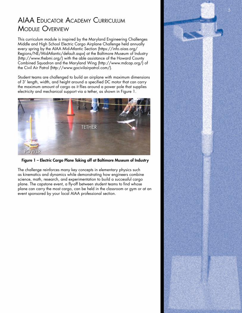
Student teams are challenged to build an airplane with maximum dimensions of 3’ length, width, and height around a specified DC motor that can carry the maximum amount of cargo as it flies around a power pole that supplies electricity and mechanical support via a tether, as shown in Figure 1.
POWER
TETHER
Figure 1 – Electric Cargo Plane Taking off at Baltimore Museum of Industry
The challenge reinforces many key concepts in elementary physics such as kinematics and dynamics while demonstrating how engineers combine science, math, research, and experimentation to build a successful cargo plane. The capstone event, a fly-off between student teams to find whose plane can carry the most cargo, can be held in the classroom or gym or at an event sponsored by your local AIAA professional section.
5
6
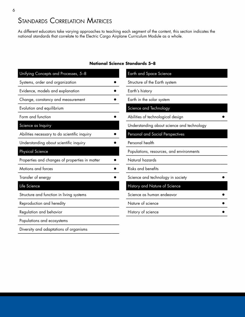
standards corrElation matricEs
As different educators take varying approaches to teaching each segment of the content, this section indicates the national standards that correlate to the Electric Cargo Airplane Curriculum Module as a whole.
Unifying Concepts and Processes, 5–8
Systems, order and organization •Evidence, models and explanation •Change, constancy and measurement •Evolution and equilibrium
Form and function •Science as Inquiry
Abilities necessary to do scientific inquiry •Understanding about scientific inquiry •Physical Science
Properties and changes of properties in matter •Motions and forces •Transfer of energy •Life Science
Structure and function in living systems
Reproduction and heredity
Regulation and behavior
Populations and ecosystems
Diversity and adaptations of organisms
Earth and Space Science
Structure of the Earth system
Earth’s history
Earth in the solar system
Science and Technology
Abilities of technological design •Understanding about science and technology
Personal and Social Perspectives
Personal health
Populations, resources, and environments
Natural hazards
Risks and benefits
Science and technology in society •History and Nature of Science
Science as human endeavor •Nature of science •History of science •
National Science Standards 5–8
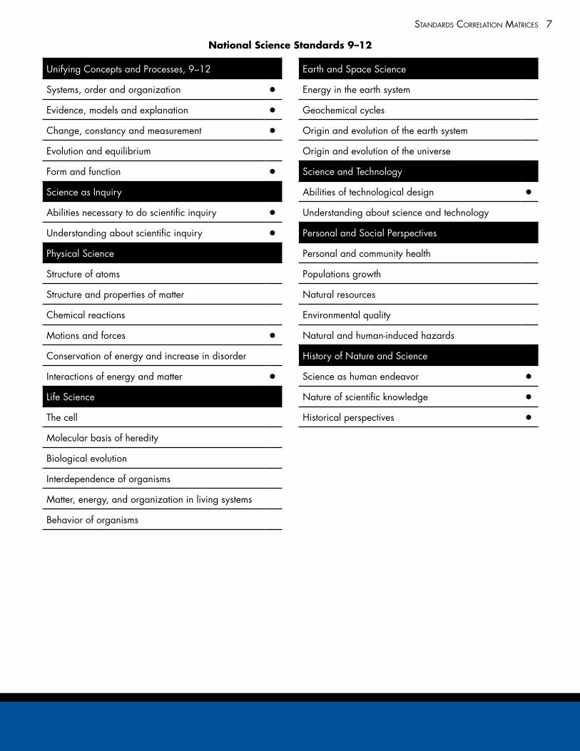
7standards corrElation matricEs
Unifying Concepts and Processes, 9–12
Systems, order and organization •Evidence, models and explanation •Change, constancy and measurement •Evolution and equilibrium
Form and function •Science as Inquiry
Abilities necessary to do scientific inquiry •Understanding about scientific inquiry •Physical Science
Structure of atoms
Structure and properties of matter
Chemical reactions
Motions and forces •Conservation of energy and increase in disorder
Interactions of energy and matter •Life Science
The cell
Molecular basis of heredity
Biological evolution
Interdependence of organisms
Matter, energy, and organization in living systems
Behavior of organisms
Earth and Space Science
Energy in the earth system
Geochemical cycles
Origin and evolution of the earth system
Origin and evolution of the universe
Science and Technology
Abilities of technological design •Understanding about science and technology
Personal and Social Perspectives
Personal and community health
Populations growth
Natural resources
Environmental quality
Natural and human-induced hazards
History of Nature and Science
Science as human endeavor •Nature of scientific knowledge •Historical perspectives •
National Science Standards 9–12
8 standards corrElation matricEs
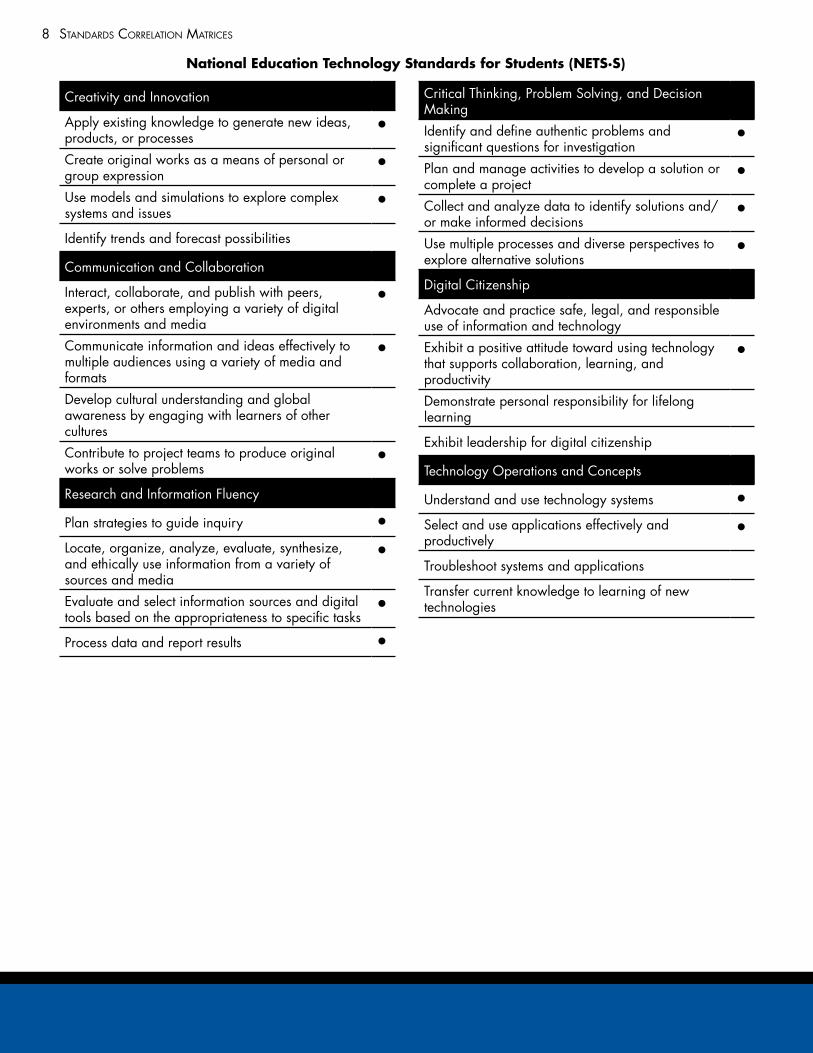
Creativity and Innovation
Apply existing knowledge to generate new ideas, products, or processes
•
Create original works as a means of personal or group expression
•
Use models and simulations to explore complex systems and issues
•
Identify trends and forecast possibilities
Communication and Collaboration
Interact, collaborate, and publish with peers, experts, or others employing a variety of digital environments and media
•
Communicate information and ideas effectively to multiple audiences using a variety of media and formats
•
Develop cultural understanding and global awareness by engaging with learners of other cultures
Contribute to project teams to produce original works or solve problems
•
Research and Information Fluency
Plan strategies to guide inquiry •Locate, organize, analyze, evaluate, synthesize, and ethically use information from a variety of sources and media
•
Evaluate and select information sources and digital tools based on the appropriateness to specific tasks
•
Process data and report results •
Critical Thinking, Problem Solving, and Decision Making
Identify and define authentic problems and significant questions for investigation
•
Plan and manage activities to develop a solution or complete a project
•
Collect and analyze data to identify solutions and/or make informed decisions
•
Use multiple processes and diverse perspectives to explore alternative solutions
•
Digital Citizenship
Advocate and practice safe, legal, and responsible use of information and technology
Exhibit a positive attitude toward using technology that supports collaboration, learning, and productivity
•
Demonstrate personal responsibility for lifelong learning
Exhibit leadership for digital citizenship
Technology Operations and Concepts
Understand and use technology systems •Select and use applications effectively and productively
•
Troubleshoot systems and applications
Transfer current knowledge to learning of new technologies
National Education Technology Standards for Students (NETS·S)
9standards corrElation matricEs
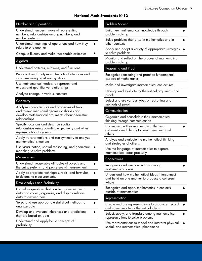
Number and Operations
Understand numbers, ways of representing numbers, relationships among numbers, and number systems
Understand meanings of operations and how they relate to one another
•
Compute fluency and make reasonable estimates •Algebra
Understand patterns, relations, and functions
Represent and analyze mathematical situations and structures using algebraic symbols
Use mathematical models to represent and understand quantitative relationships
Analyze change in various contexts
Geometry
Analyze characteristics and properties of two- and three-dimensional geometric shapes and develop mathematical arguments about geometric relationships
Specify locations and describe spatial relationships using coordinate geometry and other representational systems
Apply transformations and use symmetry to analyze mathematical situations
Use visualization, spatial reasoning, and geometric modeling to solve problems
•
Measurement
Understand measurable attributes of objects and the units, systems, and processes of measurement
•
Apply appropriate techniques, tools, and formulas to determine measurements.
•
Data Analysis and Probability
Formulate questions that can be addressed with data and collect, organize, and display relevant data to answer them
•
Select and use appropriate statistical methods to analyze data
•
Develop and evaluate inferences and predictions that are based on data
•
Understand and apply basic concepts of probability
Problem Solving
Build new mathematical knowledge through problem solving
•
Solve problems that arise in mathematics and in other contexts
•
Apply and adapt a variety of appropriate strategies to solve problems
•
Monitor and reflect on the process of mathematical problem solving
Reasoning and Proof
Recognize reasoning and proof as fundamental aspects of mathematics
Make and investigate mathematical conjectures
Develop and evaluate mathematical arguments and proofs
Select and use various types of reasoning and methods of proof
Communication
Organize and consolidate their mathematical thinking through communication
Communicate their mathematical thinking coherently and clearly to peers, teachers, and others
•
Analyze and evaluate the mathematical thinking and strategies of others;
Use the language of mathematics to express mathematical ideas precisely.
Connections
Recognize and use connections among mathematical ideas
•
Understand how mathematical ideas interconnect and build on one another to produce a coherent whole
Recognize and apply mathematics in contexts outside of mathematics
•
Representation
Create and use representations to organize, record, and communicate mathematical ideas
•
Select, apply, and translate among mathematical representations to solve problems
•
Use representations to model and interpret physical, social, and mathematical phenomena
•
National Math Standards K–12
10 standards corrElation matricEs
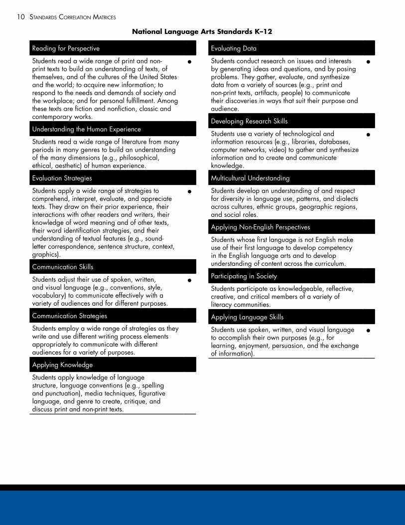
Reading for Perspective
Students read a wide range of print and non-print texts to build an understanding of texts, of themselves, and of the cultures of the United States and the world; to acquire new information; to respond to the needs and demands of society and the workplace; and for personal fulfillment. Among these texts are fiction and nonfiction, classic and contemporary works.
•
Understanding the Human Experience •Students read a wide range of literature from many periods in many genres to build an understanding of the many dimensions (e.g., philosophical, ethical, aesthetic) of human experience.
Evaluation Strategies
Students apply a wide range of strategies to comprehend, interpret, evaluate, and appreciate texts. They draw on their prior experience, their interactions with other readers and writers, their knowledge of word meaning and of other texts, their word identification strategies, and their understanding of textual features (e.g., sound-letter correspondence, sentence structure, context, graphics).
•
Communication Skills •Students adjust their use of spoken, written, and visual language (e.g., conventions, style, vocabulary) to communicate effectively with a variety of audiences and for different purposes.
•
Communication Strategies
Students employ a wide range of strategies as they write and use different writing process elements appropriately to communicate with different audiences for a variety of purposes.
Applying Knowledge •Students apply knowledge of language structure, language conventions (e.g., spelling and punctuation), media techniques, figurative language, and genre to create, critique, and discuss print and non-print texts.
Evaluating Data •Students conduct research on issues and interests by generating ideas and questions, and by posing problems. They gather, evaluate, and synthesize data from a variety of sources (e.g., print and non-print texts, artifacts, people) to communicate their discoveries in ways that suit their purpose and audience.
•
Developing Research Skills •Students use a variety of technological and information resources (e.g., libraries, databases, computer networks, video) to gather and synthesize information and to create and communicate knowledge.
•
Multicultural Understanding •Students develop an understanding of and respect for diversity in language use, patterns, and dialects across cultures, ethnic groups, geographic regions, and social roles.
Applying Non-English Perspectives
Students whose first language is not English make use of their first language to develop competency in the English language arts and to develop understanding of content across the curriculum.
Participating in Society •Students participate as knowledgeable, reflective, creative, and critical members of a variety of literacy communities.
Applying Language Skills
Students use spoken, written, and visual language to accomplish their own purposes (e.g., for learning, enjoyment, persuasion, and the exchange of information).
•
National Language Arts Standards K–12
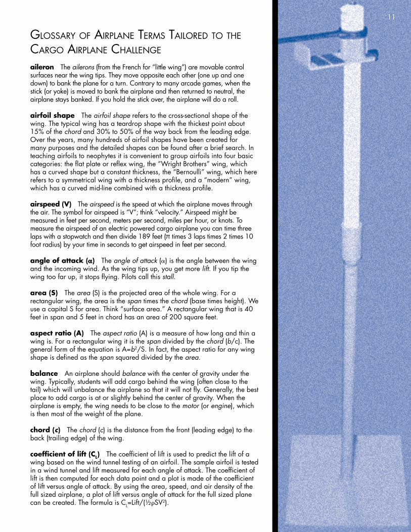
glossary of airplanE tErms tailorEd to thE cargo airplanE challEngE
aileron The ailerons (from the French for “little wing”) are movable control surfaces near the wing tips. They move opposite each other (one up and one down) to bank the plane for a turn. Contrary to many arcade games, when the stick (or yoke) is moved to bank the airplane and then returned to neutral, the airplane stays banked. If you hold the stick over, the airplane will do a roll.
airfoil shape The airfoil shape refers to the cross-sectional shape of the wing. The typical wing has a teardrop shape with the thickest point about 15% of the chord and 30% to 50% of the way back from the leading edge. Over the years, many hundreds of airfoil shapes have been created for many purposes and the detailed shapes can be found after a brief search. In teaching airfoils to neophytes it is convenient to group airfoils into four basic categories: the flat plate or reflex wing, the “Wright Brothers” wing, which has a curved shape but a constant thickness, the “Bernoulli” wing, which here refers to a symmetrical wing with a thickness profile, and a “modern” wing, which has a curved mid-line combined with a thickness profile.
airspeed (V) The airspeed is the speed at which the airplane moves through the air. The symbol for airspeed is “V”; think “velocity.” Airspeed might be measured in feet per second, meters per second, miles per hour, or knots. To measure the airspeed of an electric powered cargo airplane you can time three laps with a stopwatch and then divide 189 feet (π times 3 laps times 2 times 10 foot radius) by your time in seconds to get airspeed in feet per second.
angle of attack (α) The angle of attack (α) is the angle between the wing and the incoming wind. As the wing tips up, you get more lift. If you tip the wing too far up, it stops flying. Pilots call this stall.
area (S) The area (S) is the projected area of the whole wing. For a rectangular wing, the area is the span times the chord (base times height). We use a capital S for area. Think “surface area.” A rectangular wing that is 40 feet in span and 5 feet in chord has an area of 200 square feet.
aspect ratio (A) The aspect ratio (A) is a measure of how long and thin a wing is. For a rectangular wing it is the span divided by the chord (b/c). The general form of the equation is A=b2/S. In fact, the aspect ratio for any wing shape is defined as the span squared divided by the area.
balance An airplane should balance with the center of gravity under the wing. Typically, students will add cargo behind the wing (often close to the tail) which will unbalance the airplane so that it will not fly. Generally, the best place to add cargo is at or slightly behind the center of gravity. When the airplane is empty, the wing needs to be close to the motor (or engine), which is then most of the weight of the plane.
chord (c) The chord (c) is the distance from the front (leading edge) to the back (trailing edge) of the wing.
coefficient of lift (CL) The coefficient of lift is used to predict the lift of a wing based on the wind tunnel testing of an airfoil. The sample airfoil is tested in a wind tunnel and lift measured for each angle of attack. The coefficient of lift is then computed for each data point and a plot is made of the coefficient of lift versus angle of attack. By using the area, speed, and air density of the full sized airplane, a plot of lift versus angle of attack for the full sized plane can be created. The formula is CL=Lift/(½ρSV2).
11
glossary of airplanE tErms tailorEd to thE cargo airplanE challEngE
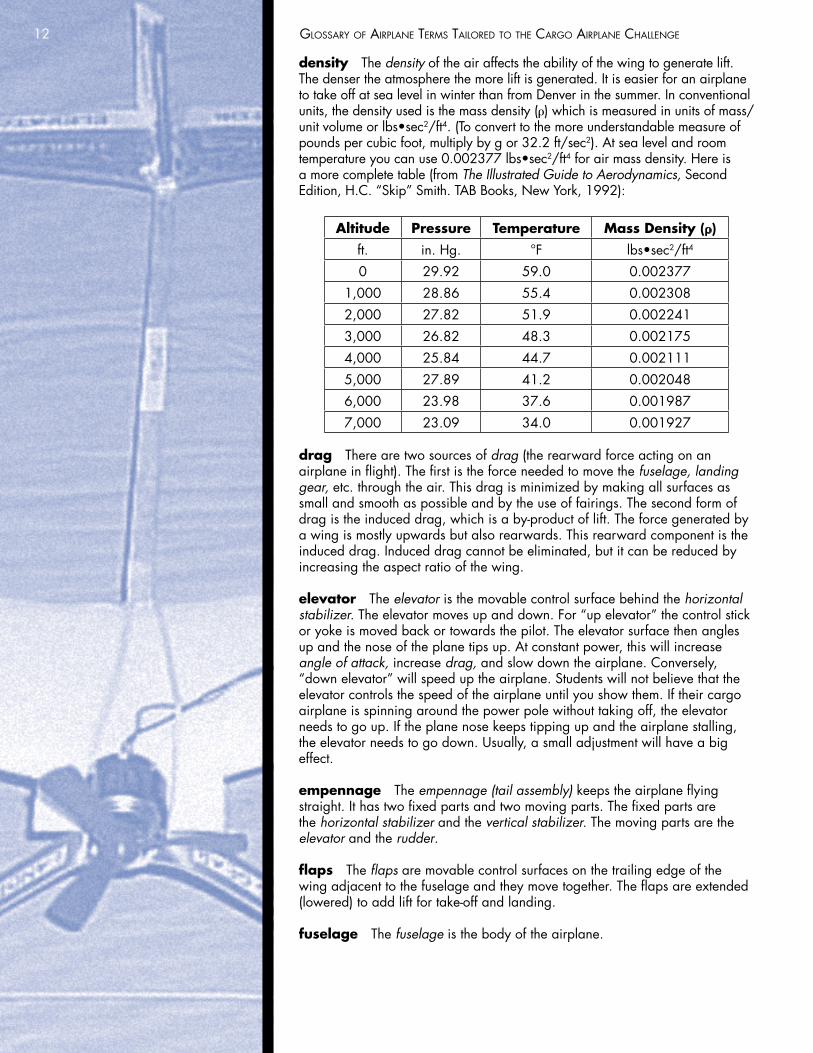
density The density of the air affects the ability of the wing to generate lift. The denser the atmosphere the more lift is generated. It is easier for an airplane to take off at sea level in winter than from Denver in the summer. In conventional units, the density used is the mass density (ρ) which is measured in units of mass/unit volume or lbs•sec2/ft4. (To convert to the more understandable measure of pounds per cubic foot, multiply by g or 32.2 ft/sec2). At sea level and room temperature you can use 0.002377 lbs•sec2/ft4 for air mass density. Here is a more complete table (from The Illustrated Guide to Aerodynamics, Second Edition, H.C. “Skip” Smith. TAB Books, New York, 1992):
Altitude Pressure Temperature Mass Density (ρ)ft. in. Hg. °F lbs•sec2/ft4
0 29.92 59.0 0.002377
1,000 28.86 55.4 0.002308
2,000 27.82 51.9 0.002241
3,000 26.82 48.3 0.002175
4,000 25.84 44.7 0.002111
5,000 27.89 41.2 0.002048
6,000 23.98 37.6 0.001987
7,000 23.09 34.0 0.001927
drag There are two sources of drag (the rearward force acting on an airplane in flight). The first is the force needed to move the fuselage, landing gear, etc. through the air. This drag is minimized by making all surfaces as small and smooth as possible and by the use of fairings. The second form of drag is the induced drag, which is a by-product of lift. The force generated by a wing is mostly upwards but also rearwards. This rearward component is the induced drag. Induced drag cannot be eliminated, but it can be reduced by increasing the aspect ratio of the wing.
elevator The elevator is the movable control surface behind the horizontal stabilizer. The elevator moves up and down. For “up elevator” the control stick or yoke is moved back or towards the pilot. The elevator surface then angles up and the nose of the plane tips up. At constant power, this will increase angle of attack, increase drag, and slow down the airplane. Conversely, “down elevator” will speed up the airplane. Students will not believe that the elevator controls the speed of the airplane until you show them. If their cargo airplane is spinning around the power pole without taking off, the elevator needs to go up. If the plane nose keeps tipping up and the airplane stalling, the elevator needs to go down. Usually, a small adjustment will have a big effect.
empennage The empennage (tail assembly) keeps the airplane flying straight. It has two fixed parts and two moving parts. The fixed parts are the horizontal stabilizer and the vertical stabilizer. The moving parts are the elevator and the rudder.
flaps The flaps are movable control surfaces on the trailing edge of the wing adjacent to the fuselage and they move together. The flaps are extended (lowered) to add lift for take-off and landing.
fuselage The fuselage is the body of the airplane.
12
glossary of airplanE tErms tailorEd to thE cargo airplanE challEngE
horizontal stabilizer The horizontal stabilizer is the fixed horizontal part of the empennage (tail). Together with the vertical stabilizer it keeps the airplane flying straight and level.
landing gear The landing gear (the wheels and what supports them) keeps the fuselage and propeller off of the ground.
lift The lift of the wing overcomes the weight of the plane. The factors that affect lift are the wing area, angle of attack, airfoil shape, airspeed, aspect ratio, and air density.
motor The electric motor on our cargo airplane turns the propeller to provide thrust. Most full-sized airplanes use a fuel-burning engine to turn the propeller. The throttle controls the speed of the engine. If you add throttle, the airplane will climb. If you reduce throttle the airplane will descend. Throttle controls climb and descend. If you want to change the speed of the airplane you use the elevator.
planform The shape of the wing when looked at from above is the planform. The first airplanes all had rectangular wings. Then aeronautical engineers figured out that an elliptical shape was most efficient. When this turned out to be rather difficult to construct, the trapezoidal wing was developed. As the speed of airplanes approached and then exceeded the speed of sound, these trapezoidal wings became swept back. As the swept back angle increased the taper ratio was also increased to get the typical airliner wing we see today.
quarter chord point Theoretically, the lift of an airfoil shape is centered 25% of the way from the leading edge to the trailing edge. A good cargo airplane model will balance with the tips of the fingers held beneath the wings about a fourth of the way back from the leading edge.
rudder The rudder is the movable control surface behind the vertical stabilizer. The rudder moves right and left to yaw the plane. The rudder is not the primary control surface used to turn an airplane. An airplane is turned by banking with the ailerons. The rudder is only used to coordinate the turn.
span (b) The span (b) is the width of the wing from tip to tip. Think base, as in “the base of a rectangle.”
stall When the pilot says that she stalled her airplane, she doesn’t mean that the engine stopped working. When the angle of attack is too high the wind can no longer flow smoothly over the top of the wing. Turbulent eddies are formed (think of a car driving down a dusty road). The drag increases dramatically, the airplane slows down, and the wing can no longer provide enough lift to keep the airplane flying. This is called stall.
swept back angle A wing that is not swept back sticks straight out from the side of the airplane. For a trapezoidal wing this means that the leading edge will sweep back and the trailing edge will sweep forward. The line that should go directly outward is the quarter chord line, 25% of the way from the leading to the trailing edge. It is along this quarter chord line that the swept back angle is measured. For a zero swept back angle 0.45 taper ratio trapezoidal wing (most airplanes from the end of the bi-plane era until Chuck Yeager broke the sound barrier) the leading edge will be straighter than the trailing edge. Unless taught otherwise, most students will get this backwards.
13
glossary of airplanE tErms tailorEd to thE cargo airplanE challEngE
taper ratio On a trapezoidal wing the chord at the tip is less than the chord at the wing root (next to the fuselage). The ratio of the tip chord to the root chord is called the taper ratio. For a trapezoidal wing that is not swept back, the taper ratio should be 0.45. For the electric cargo airplane challenge it is convenient to make the tip chord of trapezoidal wings half of the root chord. Here is a table of the proper taper ratio for a given swept back angle.
¼ Chord Swept Back Angle Taper Ratio–20 1.0
0 0.45
10 0.3
20 0.2
30 0.1
thrust The thrust of the propeller overcomes the drag of the wing and the fuselage.
vertical stabilizer The vertical stabilizer is the fixed vertical part of the empennage (tail). Together with the horizontal stabilizer it keeps the airplane flying straight and level. The rudder is the movable control surface behind the vertical stabilizer.
weight The weight of the plane is carried by the lift of the wing. When the lift exceeds the weight the airplane will climb. When the weight exceeds the lift the airplane will descend. In level flight, the lift is equal to the weight. So, once you fly and then weigh the cargo airplane you know how much lift the wing produced.
wing The wing provides lift.
14
background information for Educators
Historical Perspective on Flight
The following material has been adapted from NASA’s “AERONAUTICS An Educator’s Guide with Activities in Science, Mathematics, and Technology Education.”
“Birds fly, so why can’t I?” That question was probably first asked by cave dwellers watching a bird swoop through the air. Perhaps even then, people understood the advantages of human flight. The desire to defy gravity and experience the freedom of flight compelled early attempts to unravel the mysterious technique the birds had mastered proficiently.
Piloted flight and the mobility it offered to humankind would have to wait many centuries. The more immediate goal of the cave dwellers was survival. The discovery of fire by early inhabitants helped assure a permanent place on Earth for their descendants. While a small spark eventually produced the light and heat of fire, the spark for flight was imagination. Ironically, the discovery of fire would play a major role in our first flight. Fire and flight forever changed the way we lived.
The writings and voices of past civilizations provide a record of an obsession with flight. The aerial dreams of early writers are revealed in Roman and Greek mythology. The mythical father and son team of Daedalus and Icarus used artificial wings of wax and bird feathers to escape from Crete. In Greek mythology, Pegasus was a winged horse. Some writings contributed significantly to the emerging science. From the early 1480s until his death in 1519, the Florentine artist, engineer, and scientist Leonardo da Vinci dreamed of flight and produced the first drawings for an airplane, helicopter, ornithopter, and parachute.
In the early 17th century, serious aeronautical research was conducted by so-called “birdmen” and “wing flappers.” These early experimenters were erroneously convinced that wings strapped to a human body and muscle power were the answer to flight. Their daring and often dangerous experiments made scant contributions to aeronautical knowledge or progress. By the mid-17th century, serious minded experimenters had correctly decided that humans would never duplicate bird flight. They turned their attention to finding a device that would lift them into the air.
Two French paper makers, Joseph and Etienne Montgolfier, noting the way smoke from a fire lifted pieces of charred paper into the air, began experimenting with paper bags. They held paper bags, open end downward, over a fire for a while and then released them. The smoke-filled bags promptly ascended upward. Smoke, the brothers deduced, created a lifting force for would-be flyers. Scientists would later explain that when air is heated, it becomes less dense, thus creating a buoyant or lifting force in the surrounding cool air.
On September 19, 1783, a sheep, a rooster, and a duck were suspended in a basket beneath a Montgolfier balloon. The cloth and paper balloon was 17 meters high, and 12 meters in diameter. A fire was lit, and minutes later the balloon was filled with hot air; it rose majestically to a height of more than 500 meters. The farm animals survived the ordeal and became the first living creatures carried aloft in a human-made device. The dream of flight was now the reality of flight. Two months later on November 21, 1793, two volunteers stepped into the basket and flew for eight kilometers over Paris, thereby becoming the world’s first aeronauts. Flying became practical in lighter-than-air devices, and balloon mania set in.
15
background information for Educators
Throughout the 19th century, aeronauts experimented with hydrogen gas–filled balloons and struggled to devise a method to control them. After another century of experimenting, the balloon had become elongated and fitted with propulsion and steering gear. Ballooning had become a fashionable sport for the rich, a platform for daring circus acts, and provided valuable observation posts for the military. Yet none of this was flying the way birds fly – darting, diving, and soaring with no more than an effortless flick of wings. To escape the limitations of a floating craft, early researchers began the search for another, more exciting form of lift.
A small but dedicated handful of pioneers were convinced that the future of human flight depended more on wings and less on smoke and hot air. One of these early pioneers had an intense interest in the flight of birds and became obsessed with ways its principles might be adapted by humans. As early as 1796, Englishman George Cayley conducted basic research on aerodynamics by attaching bird feathers to a rotating shaft, thereby building and flying a model helicopter. In 1804, he built and flew the world’s first fixed-wing flyable model glider. This pioneering model used a paper kite wing mounted on a slender wooden pole. A tail was supported at the rear of the pole providing horizontal and vertical control. It was the first true airplane-like device in history.
In 1849, after years of extensive and persistent research, Cayley constructed his “boy glider.” This full-sized heavier-than-air craft lifted a 10-year-old boy a few meters off the ground during two test runs. Four years later, Sir George Cayley persuaded his faithful coachman to climb aboard another glider and make the world’s first piloted flight in a fixed-wing glider.
In Germany, Otto Lilienthal believed that arched or curved wings held the secret to the art of flight. In his Berlin workshop, Lilienthal built test equipment to measure the amount of lift that various shapes of wings produced. His work clearly demonstrated the superior lifting quality of the curved wing. By 1894, Lilienthal’s unpowered flying machines were achieving spectacular glides of over 300 meters in distance. Lilienthal built a 2 1/2 horsepower carbonic acid gas engine weighing 90 pounds. He was ready to begin powered glider experiments. Unfortunately, Lilienthal was killed in an 1896 glider mishap before he could test his power-driven airplane.
Otto Lilienthal left behind an inspiration and a warning. If his life’s work proved that we could fly, then his death was a somber warning. Humans would have to master the aerodynamics of wings before flight like the birds could be accomplished with confidence and safety. His extensive research and experiments in aviation brought the world closer to realizing the age-old dream of human flight.
Lilienthal’s work was carried forward by one of his students, a Scotsman named Percy Pilcher. Like Lilienthal, Pilcher built his own engine in hopes of achieving powered flight. Ironically, before he could conduct any experiments with powered flight, Pilcher was killed in a glider accident in 1899.
As the 19th century drew to a close, aviation pioneers continued to probe the mystery surrounding mechanical flight. Octave Chanute, Samuel Langley, and others experimented to produce further understanding of aeronautical principles, yet did not achieve controlled, powered flight. In 1900, the world waited for a lightweight power source and a method to control flight.
16
background information for Educators
On May 30, 1899 Wilbur Wright wrote to the Smithsonian Institution in Washington, D.C. requesting information about published materials on aeronautics. By early summer of that year, Wilbur and his brother Orville had read everything they could find on the subject. The Wright brothers began a systematic study of the problem of flight by conducting research on the methods tried by previous experimenters. They conducted hundreds of wind tunnel experiments, engine and propeller tests, and glider flights to gain the knowledge and skill needed to fly.
On December 17, 1903, four years after beginning their research, the world was forever changed. A fragile cloth and wood airplane rose into the air from a windswept beach at Kitty Hawk, North Carolina, and flew a distance of 36 meters. The brothers provided the world with a powered flying machine controlled by the person it carried aloft. Ingenuity, persistence, and inventiveness had finally paid a big dividend – the Wright Flyer was successful. This 12-second event marked the beginning of tangible progress in the development of human-carrying, power-driven airplanes.
By 1905, an improved Wright Flyer could fly more than 32 kilometers and stay aloft almost 40 minutes. Five years later, the first international air meet in the United States was held in Los Angeles, California. Glenn Curtiss set a new world’s speed record of 88 kilometers per hour and Frenchman Louis Paulhan set an altitude record of 1250 meters. At the outbreak of World War I, the airplane could fly at speeds of over 200 kilometers per hour and reach altitudes of 7500 meters.
The Congress of the United States recognized that a new era in transportation was beginning and the changes would have significant impact on human interchange, commerce, foreign relations, and military strategy. Flight research in the United States got a significant boost in 1915. The National Advisory Committee for Aeronautics (NACA) was formed by the United States Congress “to supervise and direct the scientific study of the problems of flight, with a view to their practical solutions.”
By the 1930s, NACA wind tunnels and flight test investigations led to improvements in aircraft performance and safety. Research produced new airfoil or wing shapes and propeller designs that increased the safety and efficiency of airplanes. New engine cowlings and aerodynamic streamlining reduced drag and increased aircraft speed.
Today NACA’s successor, the National Aeronautics and Space Administration (NASA), has a much broader mission. As its name implies, NASA continues research to keep aviation on the cutting edge of technology for airfoils, materials, construction techniques, engines, propellers, air traffic control, agriculture development, electronics, efficiency, and safety. NASA is striving to make airplanes ecologically safe by lessening the sonic boom for aircraft traveling at supersonic speeds and developing propulsion systems that use pollutant-free fuel.
On August 17, 1978 near Paris, France, a hot air balloon descended from the sky and landed in a cornfield. Thousands of onlookers watched and cheered as the three crew members stepped down from the Double Eagle II. They had just completed the first nonstop crossing of the Atlantic Ocean in a balloon. Almost two hundred years earlier in 1783, Parisians cheered the Montgolfier brothers as they launched the first hot air balloon. The time span between the two events is filled with flight milestones that have taken humankind from the dream of flight to landing on the moon.
17
18
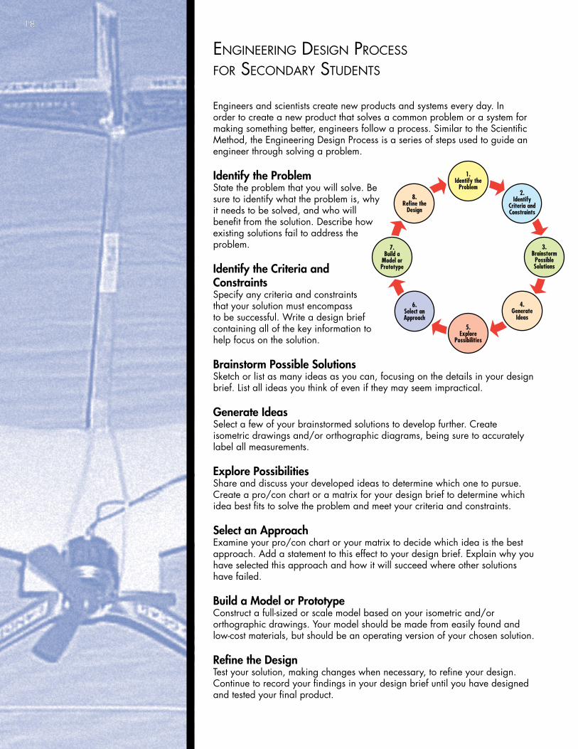
EnginEEring dEsign procEss for sEcondary studEnts
Engineers and scientists create new products and systems every day. In order to create a new product that solves a common problem or a system for making something better, engineers follow a process. Similar to the Scientific Method, the Engineering Design Process is a series of steps used to guide an engineer through solving a problem.
Identify the ProblemState the problem that you will solve. Be sure to identify what the problem is, why it needs to be solved, and who will benefit from the solution. Describe how existing solutions fail to address the problem.
Identify the Criteria and ConstraintsSpecify any criteria and constraints that your solution must encompass to be successful. Write a design brief containing all of the key information to help focus on the solution.
Brainstorm Possible SolutionsSketch or list as many ideas as you can, focusing on the details in your design brief. List all ideas you think of even if they may seem impractical.
Generate IdeasSelect a few of your brainstormed solutions to develop further. Create isometric drawings and/or orthographic diagrams, being sure to accurately label all measurements.
Explore PossibilitiesShare and discuss your developed ideas to determine which one to pursue. Create a pro/con chart or a matrix for your design brief to determine which idea best fits to solve the problem and meet your criteria and constraints.
Select an ApproachExamine your pro/con chart or your matrix to decide which idea is the best approach. Add a statement to this effect to your design brief. Explain why you have selected this approach and how it will succeed where other solutions have failed.
Build a Model or PrototypeConstruct a full-sized or scale model based on your isometric and/or orthographic drawings. Your model should be made from easily found and low-cost materials, but should be an operating version of your chosen solution.
Refine the DesignTest your solution, making changes when necessary, to refine your design. Continue to record your findings in your design brief until you have designed and tested your final product.
1.Identify the
Problem2.
IdentifyCriteria andConstraints
3.Brainstorm
PossibleSolutions
4.Generate
Ideas5.
ExplorePossibilities
6.Select anApproach
7.Build a
Model orPrototype
8.Refine the
Design
18
19
ElEctric cargo airplanE challEngE unit plan
Week 1
Generate student interest in the challenge by having an existing cargo airplane flying on the power pole when students first enter the room. This will also show students that a solution is possible and that, later on, if their airplane won’t fly it is possible to adjust or modify it until it does.
Students can be assigned teams of one or two at this point or at the beginning of week two. Although the challenge problem allows larger teams, when the cargo airplane challenge is done as a classroom activity two students are sufficient.
The first two steps in the engineering design process are to identify the problem and to identify the criteria and constraints.
Identify the Problem Review the challenge guide with the students. The key points in identifying the problem are:• Design and construct an electric powered cargo airplane.• Teams are responsible for building wings, fuselage, landing gear, and cargo.• Airplane will be weighed after flying without cargo and then again after flying with cargo.• Goal is to carry as much cargo as possible.If the class plans on participating in the Cargo Airplane Capstone event, teachers will need to review competition rules and register for the event.
Identify Criteria and Constraints.
The challenge will be judged in four areas—the design and construction of the project, a written report, an oral report, and the performance demonstration. The criteria are:• WRITTEN REPORT Competition value: 20 points • ORAL REPORT Competition value: 20 points • DESIGN AND CONSTRUCTION Competition value: 30 points. • PERFORMANCE DEMONSTRATION Competition value: 30 points
Some of the constraints on this challenge are:• Length, width, and height must all be less than 3 feet.• Every airplane uses the same motor (Kelvin #850647).• Teams may use the propeller provided or substitute their own propeller.• Airplanes will use power supplied by a power pole, limited by the maximum output of the transformer, KELVIN
Digital Power Supply 841051 (rated 0–16 volts at 1.5 amps).• Tethers must be long enough so that the distance from the pylon’s center point to the plane’s centerline is at least
10 feet.• No lighter-than-air devices are permitted.• NO COMMERCIAL KITS are permitted.
The remainder of the week should be spent with students learning the STEM involved in this challenge. The difference between students who design and construct an airplane and students who make something that only looks like an airplane is a thorough understanding of airplane design. Topics that can be covered include: • History of flight• Parts of an airplane• Forces on an airplane (lift, weight, thrust, drag)• Basic airfoils• Angle of attack and stall• Wing geometry (span, chord, area, aspect ratio, taper ratio) for
rectangular, elliptical, and trapezoidal planforms.
Forces on an Airplane
The wing must generate enough Lift (L) to carry the weight (W) of the airplane. The actual force developed by the wing is upward and slightly to the rear, so producing lift induces drag (D). The fuselage, appendages, and other sources also create drag. The total drag must be overcome by the thrust (T) of the propeller.
20 ElEctric cargo airplanE challEngE unit plan
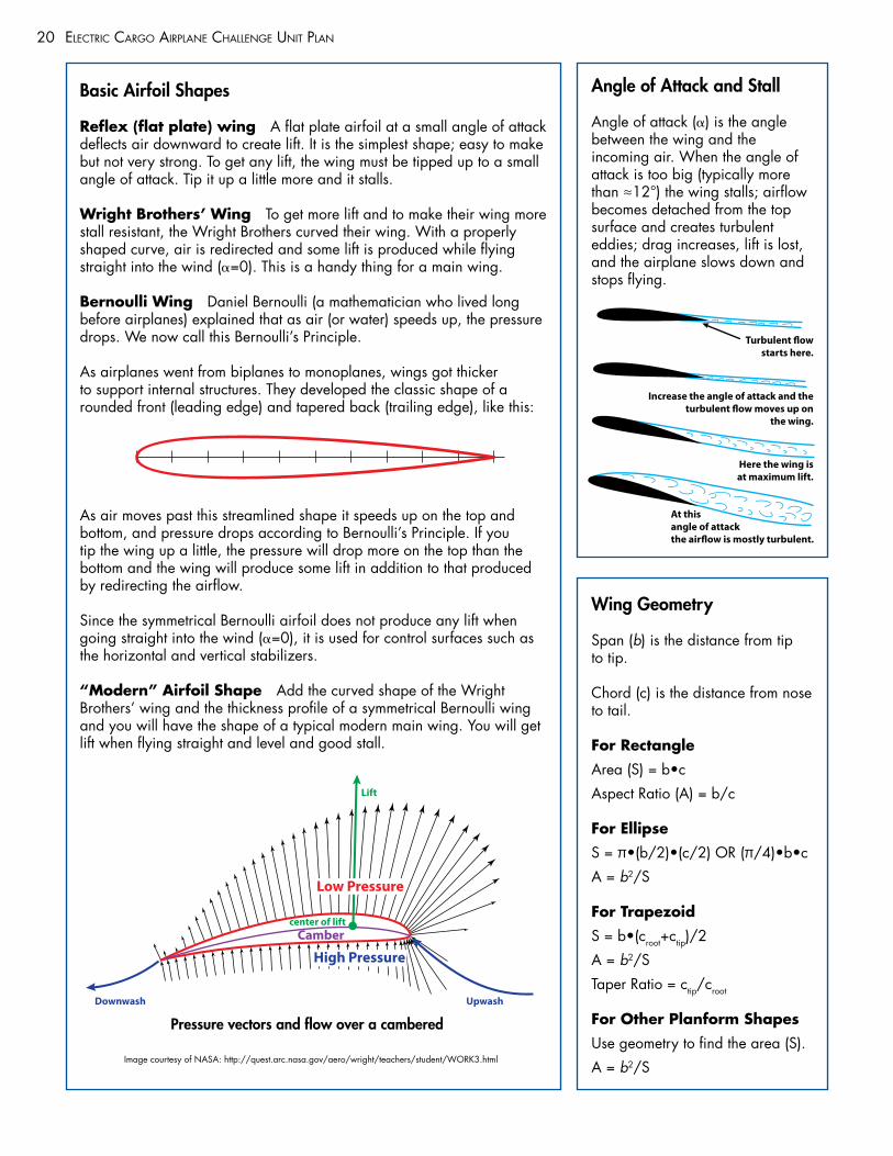
Basic Airfoil Shapes
Reflex (flat plate) wing A flat plate airfoil at a small angle of attack deflects air downward to create lift. It is the simplest shape; easy to make but not very strong. To get any lift, the wing must be tipped up to a small angle of attack. Tip it up a little more and it stalls.
Wright Brothers’ Wing To get more lift and to make their wing more stall resistant, the Wright Brothers curved their wing. With a properly shaped curve, air is redirected and some lift is produced while flying straight into the wind (α=0). This is a handy thing for a main wing.
Bernoulli Wing Daniel Bernoulli (a mathematician who lived long before airplanes) explained that as air (or water) speeds up, the pressure drops. We now call this Bernoulli’s Principle.
As airplanes went from biplanes to monoplanes, wings got thicker to support internal structures. They developed the classic shape of a rounded front (leading edge) and tapered back (trailing edge), like this:
As air moves past this streamlined shape it speeds up on the top and bottom, and pressure drops according to Bernoulli’s Principle. If you tip the wing up a little, the pressure will drop more on the top than the bottom and the wing will produce some lift in addition to that produced by redirecting the airflow.
Since the symmetrical Bernoulli airfoil does not produce any lift when going straight into the wind (α=0), it is used for control surfaces such as the horizontal and vertical stabilizers.
“Modern” Airfoil Shape Add the curved shape of the Wright Brothers’ wing and the thickness profile of a symmetrical Bernoulli wing and you will have the shape of a typical modern main wing. You will get lift when flying straight and level and good stall.
Cambercenter of lift
Lift
UpwashDownwash
High Pressure
Low Pressure
Angle of Attack and Stall
Angle of attack (α) is the angle between the wing and the incoming air. When the angle of attack is too big (typically more than ≈12°) the wing stalls; airflow becomes detached from the top surface and creates turbulent eddies; drag increases, lift is lost, and the airplane slows down and stops flying.
Wing Geometry
Span (b) is the distance from tip to tip.
Chord (c) is the distance from nose to tail.
For Rectangle
Area (S) = b•c
Aspect Ratio (A) = b/c
For Ellipse
S = π•(b/2)•(c/2) OR (π/4)•b•c
A = b2/S
For Trapezoid
S = b•(croot+ctip)/2
A = b2/S
Taper Ratio = ctip/croot
For Other Planform Shapes
Use geometry to find the area (S).
A = b2/SImage courtesy of NASA: http://quest.arc.nasa.gov/aero/wright/teachers/student/WORK3.html
Pressure vectors and flow over a cambered
At thisangle of attackthe airflow is mostly turbulent.
Here the wing isat maximum lift.
Increase the angle of attack and theturbulent flow moves up on
the wing.
Turbulent flowstarts here.
21ElEctric cargo airplanE challEngE unit plan
Week 2
The next steps in the engineering design process are to brainstorm possible solutions, generate ideas, explore possibilities, and select an approach.
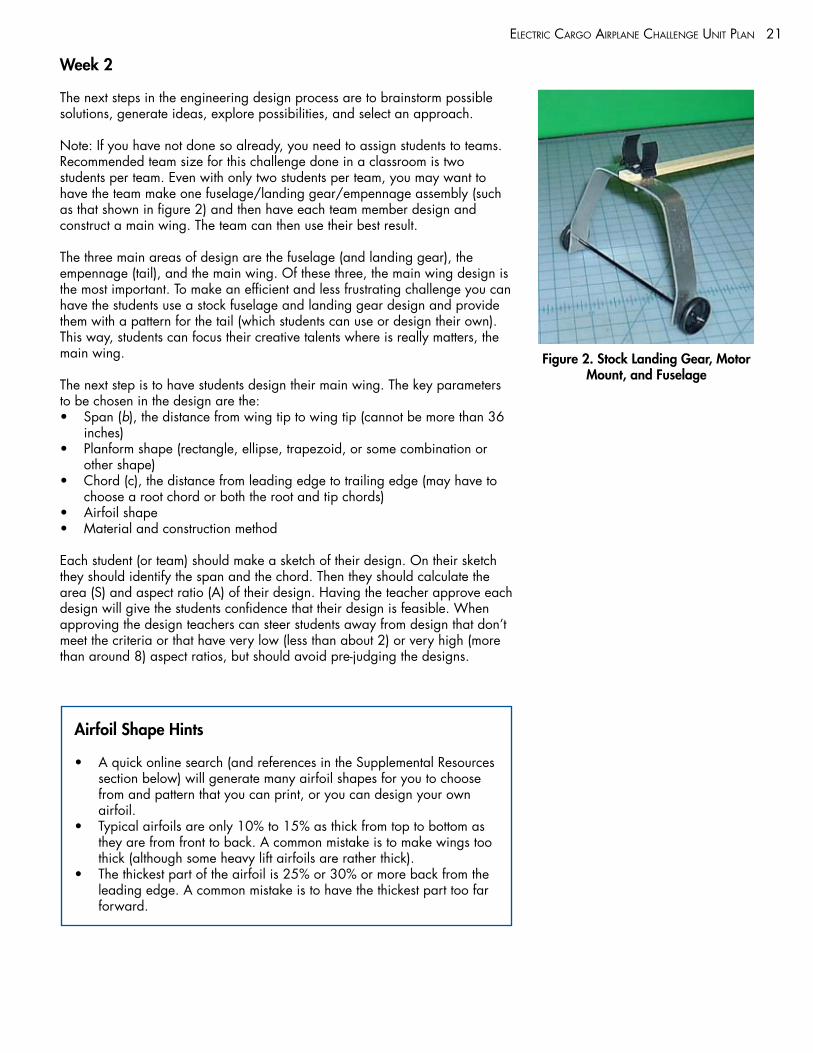
Note: If you have not done so already, you need to assign students to teams. Recommended team size for this challenge done in a classroom is two students per team. Even with only two students per team, you may want to have the team make one fuselage/landing gear/empennage assembly (such as that shown in figure 2) and then have each team member design and construct a main wing. The team can then use their best result.
The three main areas of design are the fuselage (and landing gear), the empennage (tail), and the main wing. Of these three, the main wing design is the most important. To make an efficient and less frustrating challenge you can have the students use a stock fuselage and landing gear design and provide them with a pattern for the tail (which students can use or design their own). This way, students can focus their creative talents where is really matters, the main wing.
The next step is to have students design their main wing. The key parameters to be chosen in the design are the: • Span (b), the distance from wing tip to wing tip (cannot be more than 36
inches)• Planform shape (rectangle, ellipse, trapezoid, or some combination or
other shape)• Chord (c), the distance from leading edge to trailing edge (may have to
choose a root chord or both the root and tip chords)• Airfoil shape• Material and construction method
Each student (or team) should make a sketch of their design. On their sketch they should identify the span and the chord. Then they should calculate the area (S) and aspect ratio (A) of their design. Having the teacher approve each design will give the students confidence that their design is feasible. When approving the design teachers can steer students away from design that don’t meet the criteria or that have very low (less than about 2) or very high (more than around 8) aspect ratios, but should avoid pre-judging the designs.
Figure 2. Stock Landing Gear, Motor Mount, and Fuselage
Airfoil Shape Hints
• A quick online search (and references in the Supplemental Resources section below) will generate many airfoil shapes for you to choose from and pattern that you can print, or you can design your own airfoil.
• Typical airfoils are only 10% to 15% as thick from top to bottom as they are from front to back. A common mistake is to make wings too thick (although some heavy lift airfoils are rather thick).
• The thickest part of the airfoil is 25% or 30% or more back from the leading edge. A common mistake is to have the thickest part too far forward.
22 ElEctric cargo airplanE challEngE unit plan
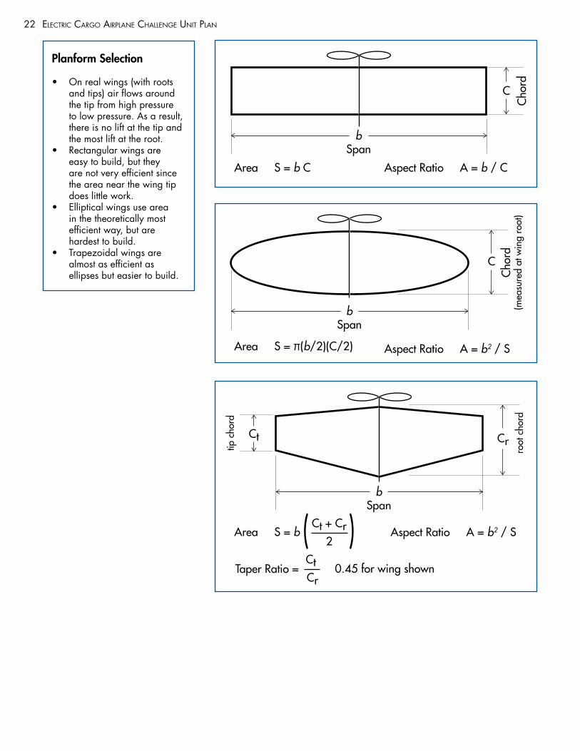
Planform Selection
• On real wings (with roots and tips) air flows around the tip from high pressure to low pressure. As a result, there is no lift at the tip and the most lift at the root.
• Rectangular wings are easy to build, but they are not very efficient since the area near the wing tip does little work.
• Elliptical wings use area in the theoretically most efficient way, but are hardest to build.
• Trapezoidal wings are almost as efficient as ellipses but easier to build.
Area S = b C
C
bSpan
bSpan
Aspect Ratio A = b / C
Area S = π(b/2)(C/2) Aspect Ratio A = b2 / S
Aspect Ratio A = b2 / SArea S = b Ct + Cr
2( )Taper Ratio =
Ct
Cr 0.45 for wing shown
bSpan
C
Cho
rdC
hord
(mea
sure
d at
win
g ro
ot)
Ct Crtip c
hord
root
cho
rd
23ElEctric cargo airplanE challEngE unit plan
Week 3
The next step in the engineering design process is to build a model or prototype.
Students will continue to work in their design teams and will:• Finish their fuselage, landing gear, and empennage assembly if not
already done.• Solder 18-inch leads to the motor (or the teacher can have done this
already).• Attach the propeller to the motor. Students can use the propeller that you
provide them, or can obtain and use their own propeller.• Mount the motor on the fuselage.• Construct the main wing.
*Review safety guidelines for using any materials and tools available in the classroom.
As teams finish their construction they should begin to fly their planes. The goal for the week is to have every team fly empty (without cargo).
An additional STEM topic that can be covered this week is aircraft controls. The two adjustments that are most important for the cargo airplanes are to get the balance correct and to adjust the elevator to produce the maximum lift without stalling.
Since these are light aircraft (without cargo) with large wings, they are hard to fly empty. Since most of the weight of the empty plane is the motor, the wing needs to start out all the way forward. With the elevator too far up or the center of gravity too far back, the plane will rise quickly off of the floor and stall, and may even flip onto its back. With the elevator too far down (small adjustments please) or the center of gravity too far forward (wing too far back), the plane will spin around the pole with its tails higher than its wing and its wheels firmly on the ground.
Help the students balance and adjust their planes to get a good empty flight. Students should weight and record the weight of their plane after it flies successfully.
Aircraft Controls
Rudder controls yaw (right or left)• On trailing edge of vertical
stabilizer• Used sparingly in
coordinated turn
Ailerons control roll (bank)• On wing end trailing edge• Operate opposed• Used for coordinated turn
Flaps add lift for takeoff and landing• On wing root trailing edge• Operate together
Throttle controls thrust• Controls engine speed
(RPM)• Controls rate of climb
Elevator controls pitch (nose up or down)• On trailing edge of
horizontal stabilizer• Operate together• Controls airspeed
24 ElEctric cargo airplanE challEngE unit plan
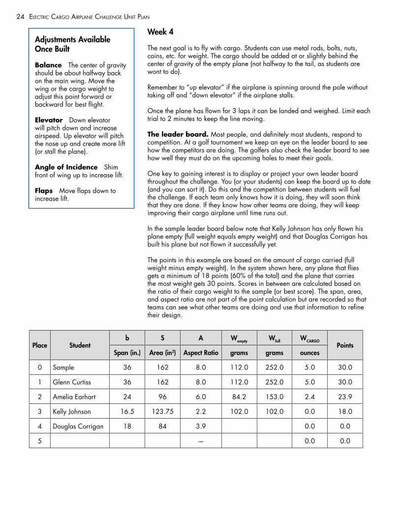
Week 4
The next goal is to fly with cargo. Students can use metal rods, bolts, nuts, coins, etc. for weight. The cargo should be added at or slightly behind the center of gravity of the empty plane (not halfway to the tail, as students are wont to do).
Remember to “up elevator” if the airplane is spinning around the pole without taking off and “down elevator” if the airplane stalls.
Once the plane has flown for 3 laps it can be landed and weighed. Limit each trial to 2 minutes to keep the line moving.
The leader board. Most people, and definitely most students, respond to competition. At a golf tournament we keep an eye on the leader board to see how the competitors are doing. The golfers also check the leader board to see how well they must do on the upcoming holes to meet their goals.
One key to gaining interest is to display or project your own leader board throughout the challenge. You (or your students) can keep the board up to date (and you can sort it). Do this and the competition between students will fuel the challenge. If each team only knows how it is doing, they will soon think that they are done. If they know how other teams are doing, they will keep improving their cargo airplane until time runs out.
In the sample leader board below note that Kelly Johnson has only flown his plane empty (full weight equals empty weight) and that Douglas Corrigan has built his plane but not flown it successfully yet.
The points in this example are based on the amount of cargo carried (full weight minus empty weight). In the system shown here, any plane that flies gets a minimum of 18 points (60% of the total) and the plane that carries the most weight gets 30 points. Scores in between are calculated based on the ratio of their cargo weight to the sample (or best score). The span, area, and aspect ratio are not part of the point calculation but are recorded so that teams can see what other teams are doing and use that information to refine their design.
Adjustments Available Once Built
Balance The center of gravity should be about halfway back on the main wing. Move the wing or the cargo weight to adjust this point forward or backward for best flight.
Elevator Down elevator will pitch down and increase airspeed. Up elevator will pitch the nose up and create more lift (or stall the plane).
Angle of Incidence Shim front of wing up to increase lift.
Flaps Move flaps down to increase lift.
Place Studentb S A Wempty Wfull WCARGO
PointsSpan (in.) Area (in2) Aspect Ratio grams grams ounces
0 Sample 36 162 8.0 112.0 252.0 5.0 30.0
1 Glenn Curtiss 36 162 8.0 112.0 252.0 5.0 30.0
2 Amelia Earhart 24 96 6.0 84.2 153.0 2.4 23.9
3 Kelly Johnson 16.5 123.75 2.2 102.0 102.0 0.0 18.0
4 Douglas Corrigan 18 84 3.9 0.0 0.0
5 — 0.0 0.0
ElEctric cargo airplanE challEngE unit plan
Week 5
The last step in the engineering design process is to refine the design. We might also add communicating your results.
The real challenge starts after the students have first flown with weight (some students might think that they are done at this point). Students can now refine their design by:• Adding cargo weight and attempting to fly with the new cargo• Modifying their wing (e.g., reshape or add flaps)• Designing and constructing an entirely new wing• Modifying the fuselage/landing gear/empennage assembly• Trying a different propeller
As an extension activity you can have students determine the Coefficient of Lift of their airplane as it flies with cargo.
Students will continue to work in their design teams to:• Finalize and submit their written report.• Prepare and present their oral report
For the Teacher
For additional AIAA Educator Academy Curriculums please visit: http://www.AIAASTEMeducation.org
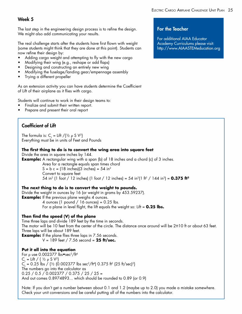
Coefficient of Lift
The formula is: CL = Lift /{½ ρ S V2}Everything must be in units of Feet and Pounds
The first thing to do is to convert the wing area into square feetDivide the area in square inches by 144.Example: A rectangular wing with a span (b) of 18 inches and a chord (c) of 3 inches.
Area for a rectangle equals span times chord S = b c = (18 inches)(3 inches) = 54 in2 Convert to square feet 54 in2 (1 foot / 12 inches) (1 foot / 12 inches) = 54 in2(1 ft2 / 144 in2) = 0.375 ft2
The next thing to do is to convert the weight to pounds.Divide the weight in ounces by 16 (or weight in grams by 453.59237).Example: If the previous plane weighs 4 ounces.
4 ounces (1 pound / 16 ounces) = 0.25 lbs. For a plane in level flight, the lift equals the weight so: Lift = 0.25 lbs.
Then find the speed (V) of the planeTime three laps and divide 189 feet by the time in seconds.The motor will be 10 feet from the center of the circle. The distance once around will be 2π10 ft or about 63 feet. Three laps will be about 189 feet.Example: If the plane flies three laps in 7.56 seconds.
V = 189 feet / 7.56 second = 25 ft/sec.
Put it all into the equationFor ρ use 0.002377 lbs•sec2/ft4CL = Lift / { ½ ρ S V2}CL = 0.25 lbs / {½ (0.002377 lbs sec2/ft4) 0.375 ft2 (25 ft/sec)2}The numbers go into the calculator as 0.25 / 0.5 / 0.002377 / 0.375 / 25 / 25 =And out comes 0.8974893... which should be rounded to 0.89 (or 0.9)
Note: If you don’t get a number between about 0.1 and 1.2 (maybe up to 2.0) you made a mistake somewhere. Check your unit conversions and be careful putting all of the numbers into the calculator.
25
appEndix
26
appEndix
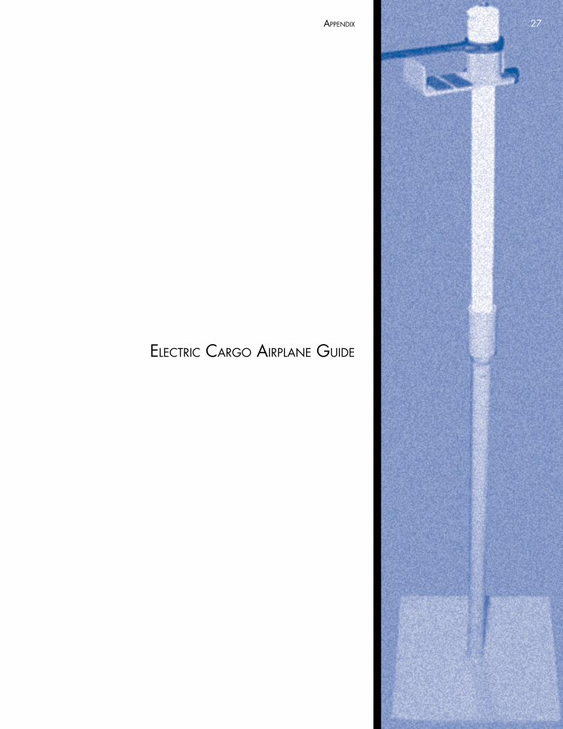
ElEctric cargo airplanE guidE
27
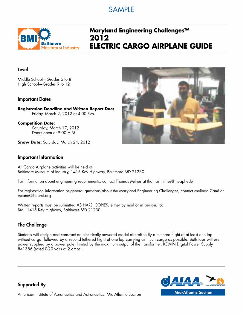
Maryland Engineering ChallengesTM
2012ELECTRIC CARGO AIRPLANE GUIDE
samplE
Level
Middle School—Grades 6 to 8High School—Grades 9 to 12
Important Dates
Registration Deadline and Written Report Due: Friday, March 2, 2012 at 4:00 P.M.
Competition Date: Saturday, March 17, 2012 Doors open at 9:00 A.M.
Snow Date: Saturday, March 24, 2012
Important Information
All Cargo Airplane activities will be held at: Baltimore Museum of Industry, 1415 Key Highway, Baltimore MD 21230
For information about engineering requirements, contact Thomas Milnes at [email protected]
For registration information or general questions about the Maryland Engineering Challenges, contact Melinda Cané at [email protected]
Written reports must be submitted AS HARD COPIES, either by mail or in person, to: BMI, 1415 Key Highway, Baltimore MD 21230
The Challenge
Students will design and construct an electrically-powered model aircraft to fly a tethered flight of at least one lap without cargo, followed by a second tethered flight of one lap carrying as much cargo as possible. Both laps will use power supplied by a power pole, limited by the maximum output of the transformer, KELVIN Digital Power Supply 841386 (rated 0-20 volts at 2 amps).
Supported By
American Institute of Aeronautics and Astronautics: Mid-Atlantic Section
samplE
Engineering Team Requirements
Each team may consist of 1 to 10 students
Design & Construction Standards:
• Teams may request one free supply kit (one motor and one propeller) from the BMI. To request your kit(s), contact Melinda Cané at [email protected]
• Additional kits may be purchased from BMI for $2 each.• Teams must use a KELVIN electric motor, item # 850647, one of which is supplied in each kit. The motor must be
installed in the airplane so as to be visible to the judges on the day of the competition.• Teams may substitute their own propeller for the one in the kit.• Teams are responsible for building wings, fuselage, and cargo.• Cargo may not have lift-increasing or drag-reducing properties for the airplane as a whole.• No lighter-than-air devices are permitted.• Length, width, and height must all be less than 3 feet.• Electrical connection to power pole is via telephone wall jack and wire. Electrical polarity for power pole is black - ,
red +, green –, yellow +• NO COMMERCIAL KITS are permitted.
Performance Guidelines:
• The airplane must fly a successful lap while tethered, first with plane empty, then with cargo.• Power must be supplied by the KELVIN power pole item # 850747 or # 851508 and KELVIN digital power supply
item # 841386 provided by the judges.• No more than two minutes will be allowed for any attempt.
Evaluation Standards:
• A lap will be considered successful when the plane flies at least as high as the pylon pivot point continuously for a complete circle.
• Tethers must be long enough so that the distance from the pylon’s center point to the plane’s centerline is at least 10 feet when the plane is tethered.
Please Note: Judges have full authority to interpret the letter and spirit of the rules.
This challenge involves four main components: the design and construction of the project, a written report, an oral report, and the performance demonstration.
WRITTEN REPORT Competition value: 20 points
ORAL REPORT Competition value: 20 points
DESIGN & CONSTRUCTION Competition value: 30 points
PERFORMANCE DEMONSTRATION Competition value: 30 points
An outline of what is required for each of these components, and general guidance on preparing for the competition, is given in the “High School Information Sheet” which should be read in connection with this document. The Information Sheet also gives detailed requirements for the design report at the high school level.
good luck to your tEam!
appEndix
high school information shEEt
30
Maryland Engineering ChallengesTM
HIGH SCHOOL INFORMATION SHEET
How to Prepare For the Competition• Form a team of interested students or friends.
• Each team must have at least one coach—a teacher or other adult to help and advise—though a single adult may coach more than one team.
• Plan the timing of the project. • Make sure everyone knows the due date for
the written report and recognizes that all major development work should be finished before then.
• Consult library books and other resources.• Test and improve the design continuously.• Keep careful records of meetings and working
drawings and share responsibility for different sections of the final report.
Notes to Adults• The Maryland Engineering Challenge organizers
would like to stress that the majority of the work on all phases of the project is to be done by the students.
• Adult assistance is to be limited to: • Mentoring students• Teaching principles applicable to the project• Assisting in production of the report and
drawings• Overseeing manufacturing of the project• Performing any process that may pose a safety
hazard to students (taking due account of their ages).
• Guidance should be in the form of questions (leading questions, if necessary) to promote creative thinking by the students.
• Consider attending a Coaches’ Workshop to get assistance for your team(s).
Evaluation Criteria
The grading for each section varies for each challenge. The information below gives an indication of what the judges are looking for in each section. For maximum points, all criteria for each section must be fulfilled.
NOTE: the criteria established by any challenge takes precedence over these general guidelines.
Written Report• Content and organization. Reports should contain all
sections described below• Style and presentation (form, format, mechanics, and
visuals)• Timeliness – 1 point will be deducted for each day
the report is late.
Oral Report• Poise of representatives• Knowledge and preparation of representatives• As part of the process in preparing for the
competition, each team must identify one or more representatives. These people will be given 5 to 10 minutes to make a presentation and answer questions, appropriate to the age of the students, on how the team designed their entry and the underlying scientific principles. Supporting materials, such as a display board with photographs of the work in progress, are often helpful here. Consult the individual challenge documents for further details of what will be required.
Design & Construction• Achievement of design specifications• Creativity of structural design• Quality of construction• Finished enhancement
Performance• Achievement of performance goals• Ease of operation• This is the most exciting part of the Engineering
Challenge Program. Each team has the opportunity to demonstrate to the judges (and usually an interested audience) that their hard work resulted in an operational project that really works!
• The judges will examine each entry to make sure it fits the specifications given in the individual challenge document (read this carefully). Points will also be awarded for creativity (any original design features), quality of construction (how well made it is), and appearance (decoration and finish).
samplE
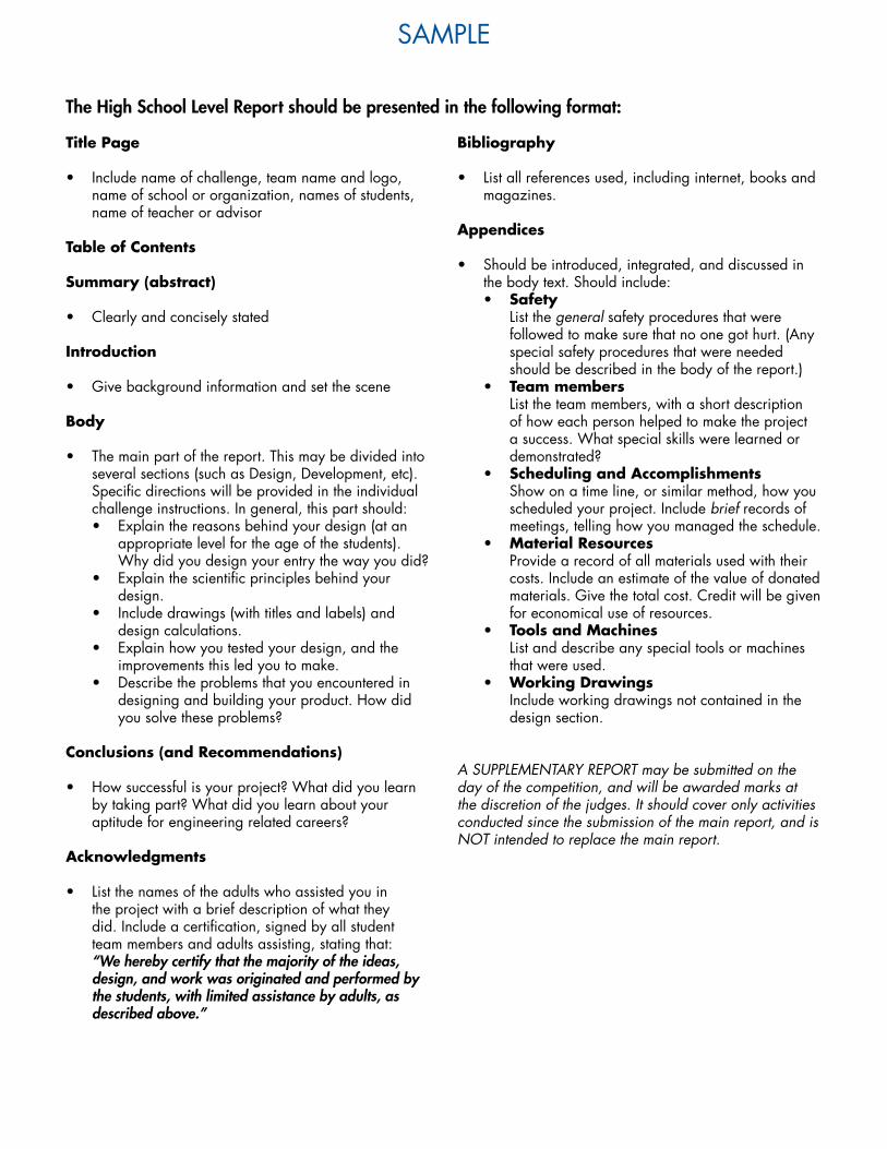
The High School Level Report should be presented in the following format:
Title Page
• Include name of challenge, team name and logo, name of school or organization, names of students, name of teacher or advisor
Table of Contents
Summary (abstract)
• Clearly and concisely stated
Introduction
• Give background information and set the scene
Body
• The main part of the report. This may be divided into several sections (such as Design, Development, etc). Specific directions will be provided in the individual challenge instructions. In general, this part should:• Explain the reasons behind your design (at an
appropriate level for the age of the students). Why did you design your entry the way you did?
• Explain the scientific principles behind your design.
• Include drawings (with titles and labels) and design calculations.
• Explain how you tested your design, and the improvements this led you to make.
• Describe the problems that you encountered in designing and building your product. How did you solve these problems?
Conclusions (and Recommendations)
• How successful is your project? What did you learn by taking part? What did you learn about your aptitude for engineering related careers?
Acknowledgments
• List the names of the adults who assisted you in the project with a brief description of what they did. Include a certification, signed by all student team members and adults assisting, stating that: “We hereby certify that the majority of the ideas, design, and work was originated and performed by the students, with limited assistance by adults, as described above.”
Bibliography
• List all references used, including internet, books and magazines.
Appendices
• Should be introduced, integrated, and discussed in the body text. Should include: • Safety
List the general safety procedures that were followed to make sure that no one got hurt. (Any special safety procedures that were needed should be described in the body of the report.)
• Team members List the team members, with a short description of how each person helped to make the project a success. What special skills were learned or demonstrated?
• Scheduling and Accomplishments Show on a time line, or similar method, how you scheduled your project. Include brief records of meetings, telling how you managed the schedule.
• Material Resources Provide a record of all materials used with their costs. Include an estimate of the value of donated materials. Give the total cost. Credit will be given for economical use of resources.
• Tools and Machines List and describe any special tools or machines that were used.
• Working Drawings Include working drawings not contained in the design section.
A SUPPLEMENTARY REPORT may be submitted on the day of the competition, and will be awarded marks at the discretion of the judges. It should cover only activities conducted since the submission of the main report, and is NOT intended to replace the main report.
samplE
supplEmEntal rEsourcEs
33appEndix
34 appEndix
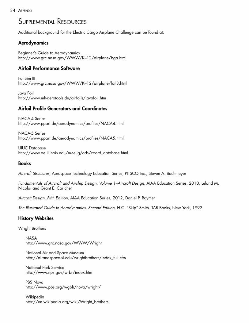
supplEmEntal rEsourcEs
Additional background for the Electric Cargo Airplane Challenge can be found at:
Aerodynamics
Beginner’s Guide to Aerodynamics http://www.grc.nasa.gov/WWW/K–12/airplane/bga.html
Airfoil Performance Software
FoilSim III http://www.grc.nasa.gov/WWW/K–12/airplane/foil3.html
Java Foil http://www.mh-aerotools.de/airfoils/javafoil.htm
Airfoil Profile Generators and Coordinates
NACA-4 Series http://www.ppart.de/aerodynamics/profiles/NACA4.html
NACA-5 Series http://www.ppart.de/aerodynamics/profiles/NACA5.html
UIUC Database http://www.ae.illinois.edu/m-selig/ads/coord_database.html
Books
Aircraft Structures, Aerospace Technology Education Series, PITSCO Inc., Steven A. Bachmeyer
Fundamentals of Aircraft and Airship Design, Volume 1–Aircraft Design, AIAA Education Series, 2010, Leland M. Nicolai and Grant E. Caricher
Aircraft Design, Fifth Edition, AIAA Education Series, 2012, Daniel P. Raymer
The Illustrated Guide to Aerodynamics, Second Edition, H.C. “Skip” Smith. TAB Books, New York, 1992
History Websites
Wright Brothers
NASA http://www.grc.nasa.gov/WWW/Wright
National Air and Space Museum http://airandspace.si.edu/wrightbrothers/index_full.cfm
National Park Service http://www.nps.gov/wrbr/index.htm
PBS Nova http://www.pbs.org/wgbh/nova/wright/
Wikipedia http://en.wikipedia.org/wiki/Wright_brothers