Embed Size (px)
Citation preview

ACI Committee 341-C
State-of-the-Art SummarySeismic Evaluation and
Retrofit Techniques for Concrete
Bridges

Committee 341-CRetrofit of Concrete
Bridges• Sub-committee members:– Dawn Lehman and Sri Sritharan (co-chairs)– Adolfo Matamoros, Anthony Powers, David
Sander (authors)– Ayman Salama, Raj Valluvan, Eric
Williamson
• Additional Contributions:– Photographs: NISEE Image Database – Analysis of SR-99: WashDOT
UW: Blake Inouye, John Stanton, Dawn Lehman

1971 San Fernando1971 San Fernando1971 San Fernando1971 San Fernando
Bridge Damage in Previous Earthquakes

1989 Loma Prieta1989 Loma Prieta1989 Loma Prieta1989 Loma Prieta
Bridge Damage in Previous Earthquakes
1994 Northridge1994 Northridge1994 Northridge1994 Northridge
Bridge Damage in Previous Earthquakes
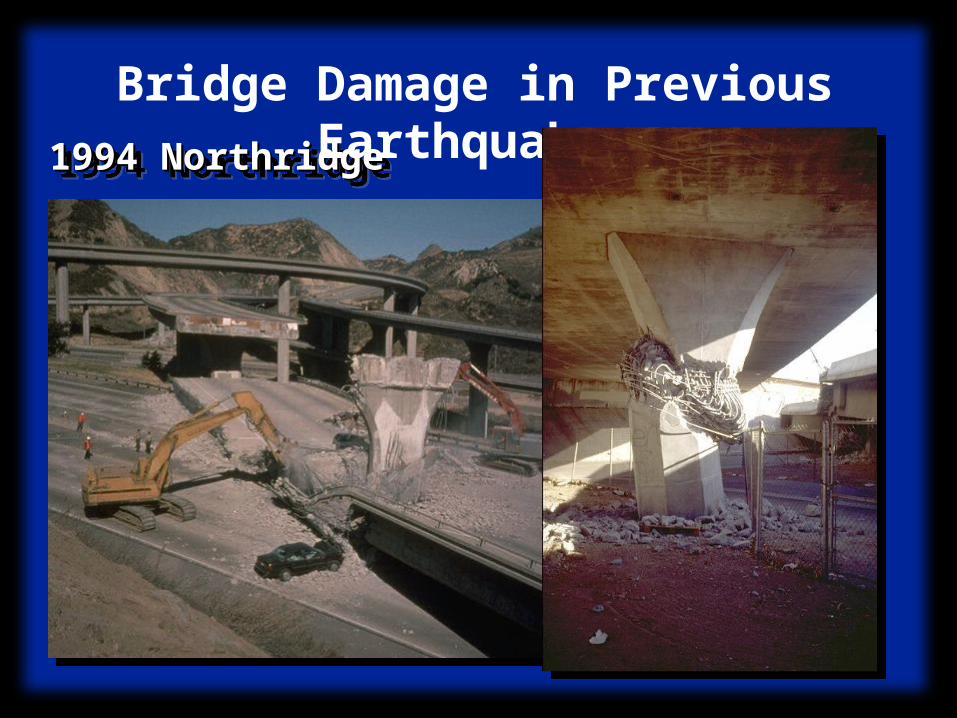
1995 Kobe1995 Kobe1995 Kobe1995 Kobe
Bridge Damage in Previous Earthquakes

Report Objectives
• Describe key aspects of seismic retrofit program– General understanding of each phase– Conceptual design and analysis methods
• Emphasize design for structural stability• Rich resource of appropriate references

Resource EvaluationMulti-Phase Program
IMPLEMENTATION
Member ResponseGlobal Response
SELECTION AND DESIGN OF RETROFIT MEASURES
SEISMIC EVALUATIONOF EXISTING
SYSTEM
System CapacitySeismic DemandDemand/Capacity Ratio
Phases of Retrofit Program
SEISMIC VULNERABILITY
EVALUATIONSeismic Hazard
Structural Vulnerabilities
Socio-Economic Consequences

Phases of Retrofit Program:Seismic Vulnerability
Evaluation• Local Soil Conditions• Soil Response and Failure
SourceSource
PathPath
SiteSite
Evaluation of Site-Specific Hazard

Phases of Retrofit Program:Seismic Vulnerability
Evaluation• Geometry• Date of Design and Construction
Evaluation of Structural Vulnerability

Phases of Retrofit Program:Seismic Vulnerability
EvaluationEvaluation of Socio-Economic Consequences• Casualties• Lifeline Interruption• Economic Impact

Phases of Retrofit Program:Seismic Demand/Capacity
Evaluation• Determine as-built conditions• Existing material properties• Estimate capacity of components
Evaluation of Seismic Capacity
(Priestley et al., 1994)

Phases of Retrofit Program:Seismic Demand/Capacity
Evaluation• Established Analysis Methods
• Linear or Nonlinear• Multi-Spectra or Time-History
Evaluation of Seismic Demand

Period
Acce
lera
tion
T
Phases of Retrofit Program:Seismic Demand/Capacity
Evaluation
Determine Demand/Capacity Ratios• Global Displacement• Local Deformations and Forces

Phases of Retrofit Program:Seismic Retrofit Measures
• Based on Demand/Capacity Evaluation• Select at Member and/or System Level• Address Global Response

Phases of Retrofit Program:Implementation• Multi-Phase Retrofit Programs• Depends on State and DOT
Figure 1.2 Typical Cable Restrainer SystemCourtesy of the University of Washington
Figure 1.2 Typical Cable Restrainer SystemCourtesy of the University of Washington
Initial Retrofit Measures
Cable Restrainer
More Costly Measures:
Beam and Column Retrofit

Sri SritharanTony Powers
SELECTION AND DESIGN OF RETROFIT MEASURES
SEISMIC EVALUATIONOF EXISTING
SYSTEM
Adolfo Matamoros
Presentation of ReportSEISMIC
VULNERABILITYEVALUATION
David Sanders
INTRODUCTIONCONCLUSIONS
EDITINGDawn Lehman
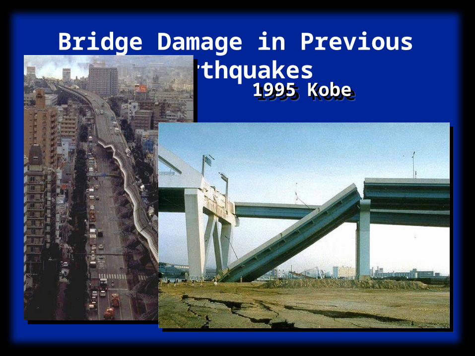
Seismic Vulnerability Evaluation
• Bridge Geometry• Structural Redundancy• Expansion Joints• Age of Design ~ Vulnerable
Elements• Structural Condition• Condition of Supporting Soil

Seismic Vulnerability Evaluation
Bridge Geometry• Bent Configurations• Degree of Skew or Curvature• Flared Columns • Short Seat Widths• Multi-Level Systems• Multiple
Superstructure Types
Seismic Vulnerability Evaluation
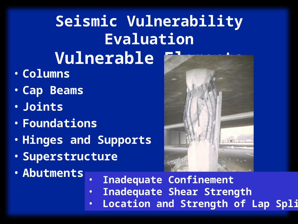
Vulnerable Elements• Columns• Cap Beams• Joints• Foundations• Hinges and Supports• Superstructure• Abutments• Inadequate Confinement
• Inadequate Shear Strength• Location and Strength of Lap Splices

Seismic Vulnerability Evaluation
Vulnerable Elements• Columns• Cap Beams• Joints• Foundations• Hinges and Supports• Superstructure• Abutments
• Reduced Flexural Strength(Insufficient Bar Anchorage)
• Inadequate Shear Strength
• Inadequate Strength in Torsion
Seismic Vulnerability Evaluation
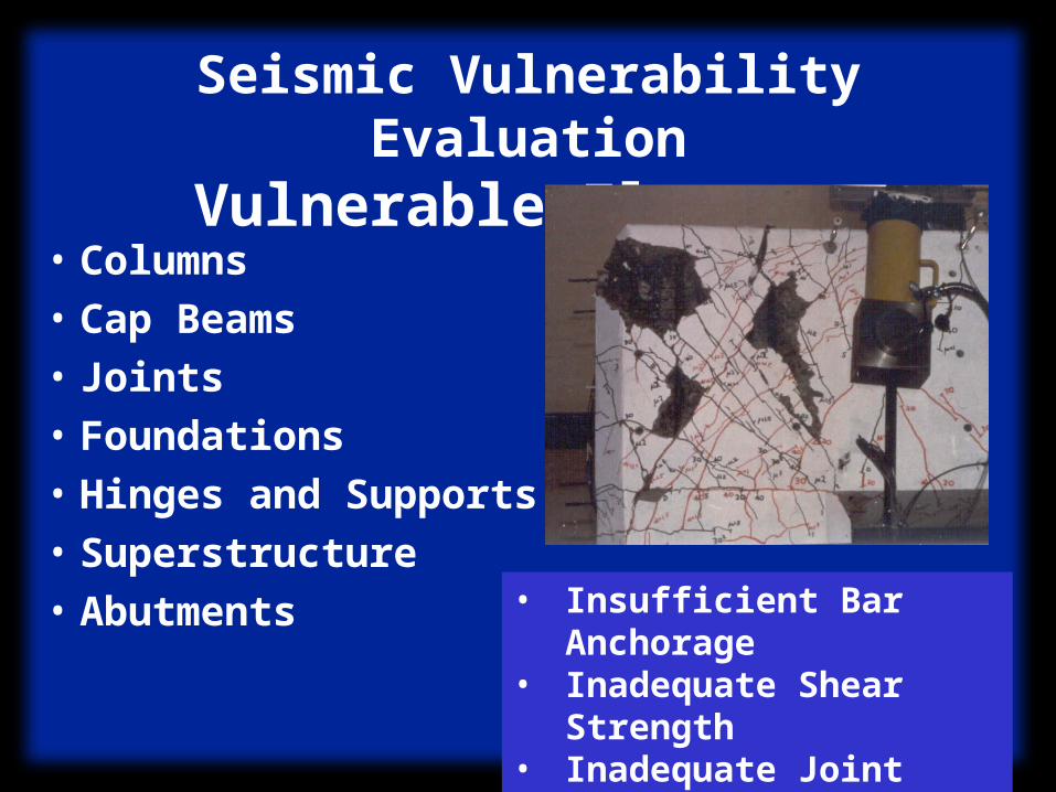
Vulnerable Elements• Columns• Cap Beams• Joints• Foundations• Hinges and Supports• Superstructure• Abutments
• Insufficient Bar Anchorage
• Inadequate Shear Strength
• Inadequate Joint Steel

Seismic Vulnerability Evaluation
Vulnerable Elements• Columns• Cap Beams• Joints• Foundations• Hinges and Supports• Superstructure• Abutments • Insufficient Flexural
Strength• Inadequate Shear
Strength• Inadequate
Anchorage
Seismic Vulnerability Evaluation
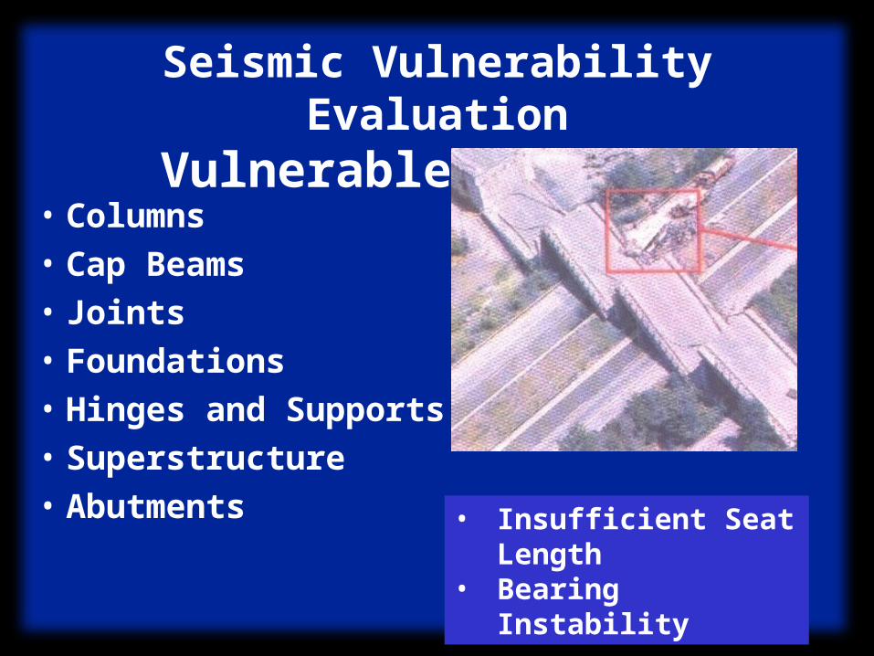
Vulnerable Elements• Columns• Cap Beams• Joints• Foundations• Hinges and Supports• Superstructure• Abutments • Insufficient Seat
Length• Bearing
Instability
Seismic Vulnerability Evaluation
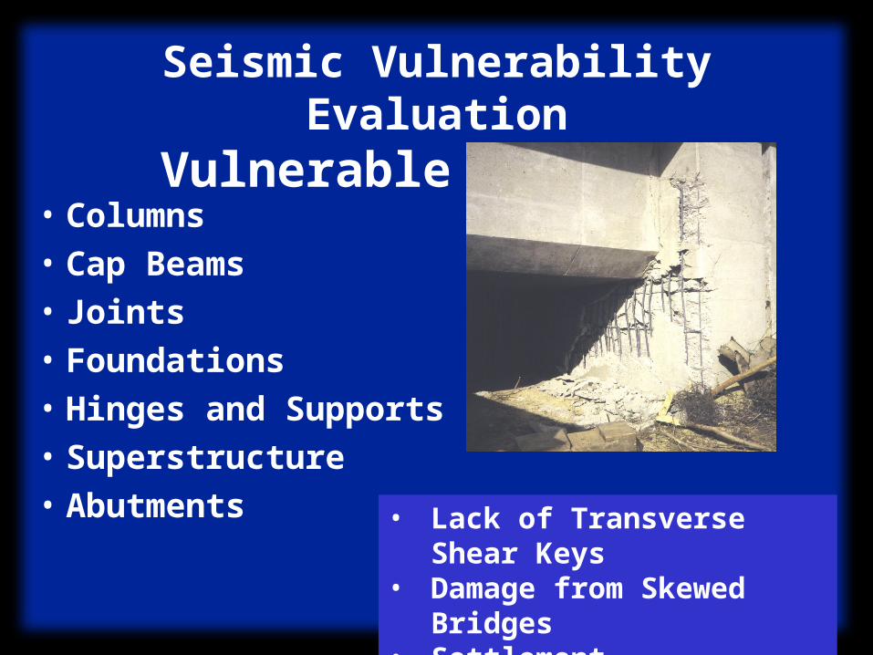
Vulnerable Elements• Columns• Cap Beams• Joints• Foundations• Hinges and Supports• Superstructure• Abutments • Lack of Transverse
Shear Keys• Damage from Skewed
Bridges• Settlement

Seismic Evaluation
• Seismic Demand• Seismic Capacity• Demand/Capacity Ratios

Seismic Evaluation:Seismic Demand
• Determine Appropriate Analysis Method– Linear– Nonlinear
• Develop Model• Evaluate Demands for Design
Earthquakes

Seismic Demand Evaluation:Appropriate Analysis
Method• Linear– Single-Mode Response Spectrum
•“Simple” System•Regular Mass and Stiffness
– Multi-Mode Response Spectra•More Complex System• Irregular Mass, Stiffness Geometry
– Time History•Complex System•Soil Springs/Dampers

Seismic Demand Evaluation:Appropriate Analysis
Method• Nonlinear Analysis Methods
– Limit or Pushover Analysis• Demands on System (Target Displacement)• Paired with a Dynamic Analysis
– Stand Alone Frame Analysis• Provides Information on Nonlinear
Behavior• Neglects Frame and Abutment Interaction
– Time History Analysis

Example of:Appropriate Analysis
Method• SR-99 Bridge• Partial Retrofit• Different
SuperstructureSystems
• Retrofit OutriggerJoints and Beams?

Example of:Appropriate Analysis
Method• Time-History Analysis
• Gap Elements
• Soil Springs
AbutmentAbutment NorthNorth + + Off-rampOff-ramp SteelSteel SouthSouthNorth North SteelSteel
Off-rampOff-ramp
AbutmentAbutment
Steel & South Steel & South Concrete StructuresConcrete Structures

Example of:Appropriate Analysis
MethodModeling Issues
– Material Strengths– Effective Stiffness Values– Stiffness of Jacketed Columns– Model of Superstructure– Stiffness of Adjacent Structures– Soil Springs and Dampers
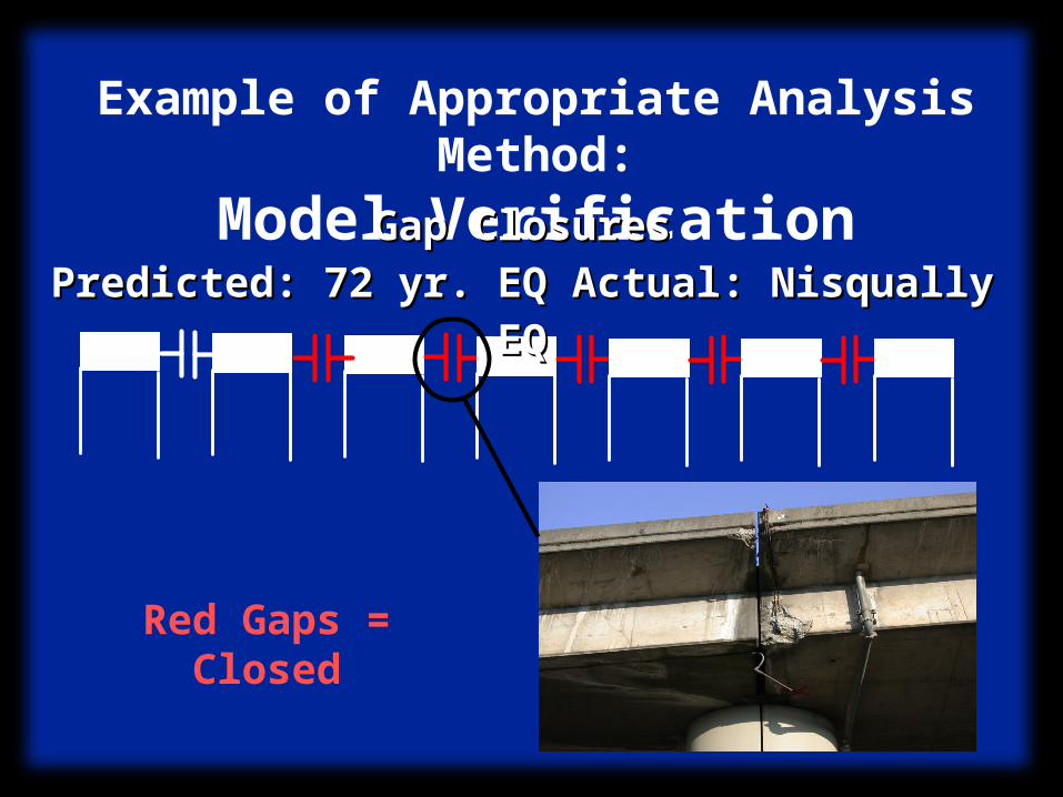
Example of Appropriate Analysis Method:
Model Verification
Red Gaps = Closed
Gap ClosuresGap Closures
Predicted: 72 yr. EQ Actual: Nisqually EQPredicted: 72 yr. EQ Actual: Nisqually EQ

Example of:Appropriate Analysis
Method Analysis Results:
• Drift Demands in Outrigger Joints
• ID Yielding Columns
From Capacity Evaluation:
• Joint Shear Stress Demands
• Beam Torsion Demands
• Beam Shear Demands
Seismic Evaluation:Seismic Capacity
• Determine Expected Material Strengths– Overstrength in Concrete: Aging– Overstrength in Steel: Strain-
Hardening, Material
• Calculate Element Capacities– Calculate Flexural Capacities– Calculate Shear Strength– Calculate Anchorage or
Development Strength

Seismic Capacity/Demand Evaluation
1. Calculate D/C Ratios for All Elements
2. Determine Critical Failure Modes/Elements
3. Determine Appropriate Retrofit Measures

Example of:Demand/Capacity Evaluation
• Critical Elements– Beam in Torsion– Exterior
Anchorage in Joint
• Retrofit Measure– Steel Jacketing
Beams & Joints

Sri SritharanTony Powers
SELECTION AND DESIGN OF RETROFIT MEASURES
SEISMIC EVALUATIONOF EXISTING
SYSTEM
Adolfo Matamoros
Presentation of Report
SEISMIC VULNERABILITY
EVALUATIONDavid Sanders

ACI Subcommittee 341–C STATE OF THE ART SUMMARY ON SEISMIC RETROFIT TECHNIQUES
FOR CONCRETE BRIDGES

Retrofit design philosophyRetrofit design philosophy
Avoid excessive damage to members and prevent
structural collapse of the bridge

Objective
• Satisfy strength and displacement demands expected under the design-level earthquakes.– Ensure a desirable yield mechanism– Limit inelastic actions to preselected locations– Column ends are typically selected in bridges– Avoid non-ductile response modes (e.g.,
shear and bond failure; inelastic response of non-ductile members)

Procedure
• Provide sufficient ductility capacity to the potential plastic hinge regions in columns
• Strengthen other members using capacity design principles using the column overstrength moments.
• Add new elements• Reduce seismic demands to avoid inelastic
response in capacity-protected members

Procedure (Cont..)
• Complete retrofit design at member level
• Analyze the retrofitted structure to ensure adequate response of the system.
• If necessary, redesign retrofit measures or introduce a new retrofit scheme

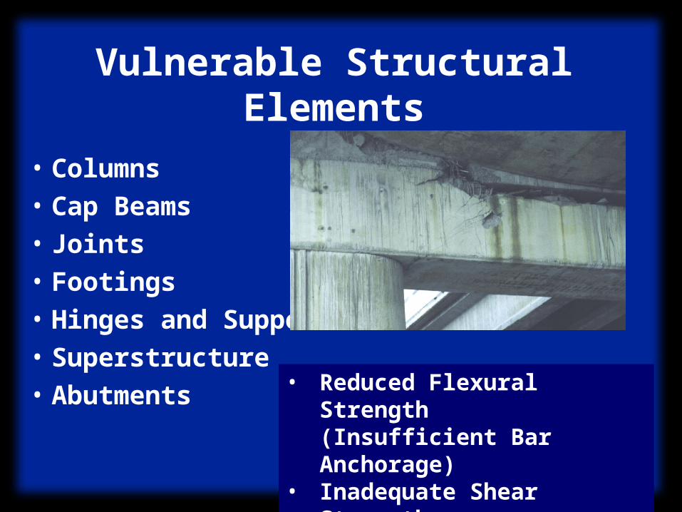
• Columns
• Cap Beams
• Joints
• Footings
• Hinges and Supports
• Superstructure
• Abutments
Vulnerable Structural Elements
• Inadequate Confinement• Inadequate Shear Strength• Location and Strength of Lap Splices

• Provide uniform pressure• Steel, concrete and advanced composites• Use wraps or jackets• Required over 1.5 to 2 times the length of
the plastic hinge region• Circular or oval shaped sections• Leave a gap between column and wrap• Fill gap with grout or concrete• Leave a gap between the column and joint
Confinement retrofit

(Courtesy of University of California, San Diego)
Confinement retrofit – Circular column
(Courtesy of Jacobs Civil Inc.)

(Courtesy of University of California, San Diego)
Rectangular column

(Courtesy of Jacobs Civil Inc.)
US40/I64 Double deck seismic retrofit in St. Louis

Active prestressed wire wraps and welded wire fabric
(Courtesy of Jacobs Civil Inc.)
Prefabricated composite jacketing of column
(Courtesy of University of Southern California)

Improved Confinement Detail
• Section with curvature ductility of 20• 10% – 75% increase in the effective
elastic stiffness• The new column stiffness should be
included in the system level analysis of the retrofitted bridge

Non-Prismatic Columns
(Courtesy of University of Nevada, Reno)
U-shaped GFRP straps
FRP straps
Half shell steel jackets

(Courtesy of University of Nevada, Reno)
Flared Columns Retrofitted with U-shaped GFRP Straps

Construction at US 395/I 80 Interchange, Reno (Courtesy of University of Nevada, Reno)
Retrofitted Bent
Multi-Column Bents – Transverse Direction

Column Lap Splice Retrofit
• Control dilatation strains
• Provide sufficient confinement
• Confinement retrofit required for the inelastic response may be sufficient
• Rectangular sections are not effective– unless spliced bars are welded for continuity

Column Retrofit to improve shear capacity
• Estimate demands– assume full development of column hinge– Include material over-strength
• Most techniques used for confinement retrofit are appropriate
• Retrofit is typically required along the full column height

(Courtesy of FHWA)
CFRP(Courtesy of University of California, San Diego)
Steel Jacket
Vulnerable Structural Elements
• Columns
• Cap Beams
• Joints
• Footings
• Hinges and Supports
• Superstructure
• Abutments• Reduced Flexural
Strength(Insufficient Bar Anchorage)
• Inadequate Shear Strength
• Inadequate Strength in Torsion

• Post-tensioning cap beam is an effective retrofit measure – may require an increase in dimensions– may require addition of end blocks– will improve joint performance– will enhance torsional resistance
• Concrete bolsters and new reinforcement• Steel jacket retrofit• FRP wraps
Cap Beam Retrofit Measures

Cap Beam Retrofit – Prestressing
(Courtesy of Jacobs Civil Inc.)(Courtesy of University of California, San Diego)

Concrete bolster
(Courtesy of University of California, Berkeley)
Adding Concrete Bolster

Reducing Seismic Demand
(Courtesy of University of California, San Diego)

Vulnerable Structural Elements
• Columns
• Cap Beams
• Joints
• Footings
• Hinges and Supports
• Superstructure
• Abutments• Insufficient Bar
Anchorage• Inadequate Shear
Strength• Inadequate Joint
Steel

• External prestressing• Complete replacement of the joint region
– increase in dimensions– Increase in column bar embedment length– new joint shear reinforcement
• Jacketing of the joint using concrete, steel or composite materials
• Reduce demand using a link beam
Joint Retrofit Measures

Joint Retrofit
(Courtesy of University of Utah)
(Courtesy of University of California, San Diego)

Complete Joint Replacement
(Courtesy of University of California, San Diego)