Embed Size (px)
Citation preview

University of Nebraska - LincolnDigitalCommons@University of Nebraska - LincolnFaculty Publications from the Department ofElectrical and Computer Engineering Electrical & Computer Engineering, Department of
2009
Achievable Rates and Resource AllocationStrategies for Imperfectly Known Fading RelayChannelsJunwei ZhangUniversity of Nebraska-Lincoln
M. Cenk GursoyUniversity of Nebraska-Lincoln, [email protected]
Follow this and additional works at: http://digitalcommons.unl.edu/electricalengineeringfacpub
Part of the Computer Engineering Commons, and the Electrical and Computer EngineeringCommons
This Article is brought to you for free and open access by the Electrical & Computer Engineering, Department of at DigitalCommons@University ofNebraska - Lincoln. It has been accepted for inclusion in Faculty Publications from the Department of Electrical and Computer Engineering by anauthorized administrator of DigitalCommons@University of Nebraska - Lincoln.
Zhang, Junwei and Cenk Gursoy, M., "Achievable Rates and Resource Allocation Strategies for Imperfectly Known Fading RelayChannels" (2009). Faculty Publications from the Department of Electrical and Computer Engineering. 360.http://digitalcommons.unl.edu/electricalengineeringfacpub/360
Hindawi Publishing CorporationEURASIP Journal on Wireless Communications and NetworkingVolume 2009, Article ID 458236, 16 pagesdoi:10.1155/2009/458236
Research Article
Achievable Rates and Resource Allocation Strategies forImperfectly Known Fading Relay Channels
Junwei Zhang andMustafa Cenk Gursoy
Department of Electrical Engineering, University of Nebraska-Lincoln, Lincoln, NE 68588, USA
Correspondence should be addressed to Mustafa Cenk Gursoy, [email protected]
Received 26 February 2009; Accepted 19 October 2009
Recommended by Michael Gastpar
Achievable rates and resource allocation strategies for imperfectly known fading relay channels are studied. It is assumed thatcommunication starts with the network training phase in which the receivers estimate the fading coefficients. Achievable rateexpressions for amplify-and-forward and decode-and-forward relaying schemes with different degrees of cooperation are obtained.We identify efficient strategies in three resource allocation problems: (1) power allocation between data and training symbols, (2)time/bandwidth allocation to the relay, and (3) power allocation between the source and relay in the presence of total powerconstraints. It is noted that unless the source-relay channel quality is high, cooperation is not beneficial and noncooperative directtransmission should be preferred at high signal-to-noise ratio (SNR) values when amplify-and-forward or decode-and-forwardwith repetition coding is employed as the cooperation strategy. On the other hand, relaying is shown to generally improve theperformance at low SNRs. Additionally, transmission schemes in which the relay and source transmit in nonoverlapping intervalsare seen to perform better in the low-SNR regime. Finally, it is noted that care should be exercised when operating at very low SNRlevels, as energy efficiency significantly degrades below a certain SNR threshold value.
Copyright © 2009 J. Zhang and M. C. Gursoy. This is an open access article distributed under the Creative Commons AttributionLicense, which permits unrestricted use, distribution, and reproduction in any medium, provided the original work is properlycited.
1. Introduction
In wireless communications, deterioration in performanceis experienced due to various impediments such as interfer-ence, fluctuations in power due to reflections and attenua-tion, and randomly-varying channel conditions caused bymobility and changing environment. Recently, cooperativewireless communication has attracted much interest as atechnique that can mitigate these degradations and providehigher rates or improve the reliability through diversitygains. The relay channel was first introduced by van derMeulen in [1], and initial research was primarily conductedto understand the rates achieved in relay channels [2, 3].More recently, diversity gains of cooperative transmissiontechniques have been studied in [4–7]. In [6], severalcooperative protocols have been proposed, with amplify-and-forward (AF) and decode-and-forward (DF) being thetwo basic relaying schemes. The performance of theseprotocols are characterized in terms of outage events andoutage probabilities. In [8], three different time-division
AF and DF cooperative protocols with different degreesof broadcasting and receive collision are studied. Resourceallocation for relay channel and networks has been addressedin several studies (see, e.g., [9–14]). In [9], upper andlower bounds on the outage and ergodic capacities of relaychannels are obtained under the assumption that the channelside information (CSI) is available at both the transmitterand receiver. Power allocation strategies are explored in thepresence of a total power constraint on the source and relay.In [10], under again the assumption of the availability of CSIat the receiver and transmitter, optimal dynamic resourceallocation methods in relay channels are identified undertotal average power constraints and delay limitations byconsidering delay-limited capacities and outage probabilitiesas performance metrics. In [11], resource allocation schemesin relay channels are studied in the low-power regime whenonly the receiver has perfect CSI. Liang et al. in [12] inves-tigated resource allocation strategies under separate powerconstraints at the source and relay nodes and showed thatthe optimal strategies differ depending on the channel statics
2 EURASIP Journal on Wireless Communications and Networking
and the values of the power constraints. Recently, the impactof channel state information (CSI) and power allocation onrates of transmission over fading relay channels are studiedin [14] by Ng and Goldsmith. The authors analyzed the casesof full CSI and receiver only CSI, considered the optimumor equal power allocation between the source and relaynodes, and identified the best strategies in different cases. Ingeneral, the area has seen an explosive growth in the numberof studies (see additionally, e.g., [15–17], and referencestherein). An excellent review of cooperative strategies fromboth rate and diversity improvement perspectives is providedin [18] in which the impacts of cooperative schemes ondevice architecture and higher-layer wireless networkingprotocols are also addressed. Recently, a special issue hasbeen dedicated to models, theory, and codes for relaying andcooperation in communication networks in [19].
As noted above, studies on relaying and cooperationare numerous. However, most work has assumed that thechannel conditions are perfectly known at the receiver and/ortransmitter sides. Especially in mobile applications, thisassumption is unwarranted as randomly varying channelconditions can be learned by the receivers only imperfectly.Moreover, the performance analysis of cooperative schemesin such scenarios is especially interesting and called forbecause relaying introduces additional channels and henceincreases the uncertainty in the model if the channelsare known only imperfectly. Recently, Wang et al. in [20]considered pilot-assisted transmission over wireless sensoryrelay networks and analyzed scaling laws achieved by theamplify-and-forward scheme in the asymptotic regimes oflarge nodes, large block length, and small signal-to-noiseratio (SNR) values. In this study, the channel conditionsare being learned only by the relay nodes. In [21, 22],estimation of the overall source-relay-destination channelis addressed for amplify-and-forward relay channels. In[21], Gao et al. considered both the least squares (LSs)and minimum-mean-square error (MMSE) estimators andprovided optimization formulations and guidelines for thedesign of training sequences and linear precoding matrices.In [22], under the assumption of fixed power allocationbetween data transmission and training, Patel and Stuberanalyzed the performance of linear MMSE estimation inrelay channels. In [21, 22], the training design is studied inan estimation-theoretic framework, and mean-square errorsand bit error rates, rather than the achievable rates, areconsidered as performance metrics. To the best of our knowl-edge, performance analysis and resource allocation strategieshave still not been sufficiently addressed for imperfectly-known relay channels in an information-theoretic contextby considering rate expressions. We note that Avestimehrand Tse in [23] studied the outage capacity of slow fadingrelay channels. They showed that Bursty Amplify-Forwardstrategy achieves the outage capacity in the low-SNR and lowoutage probability regime. Interestingly, they further provedthat the optimality of Bursty AF is preserved even if thereceivers do not have prior knowledge of the channels.
In this paper, we study the imperfectly-known fadingrelay channels. We assume that transmission takes place intwo phases: network training phase and data transmission
Relay
Source Destination
yr xr
hsrhrd
xshsd
yd,r
yd
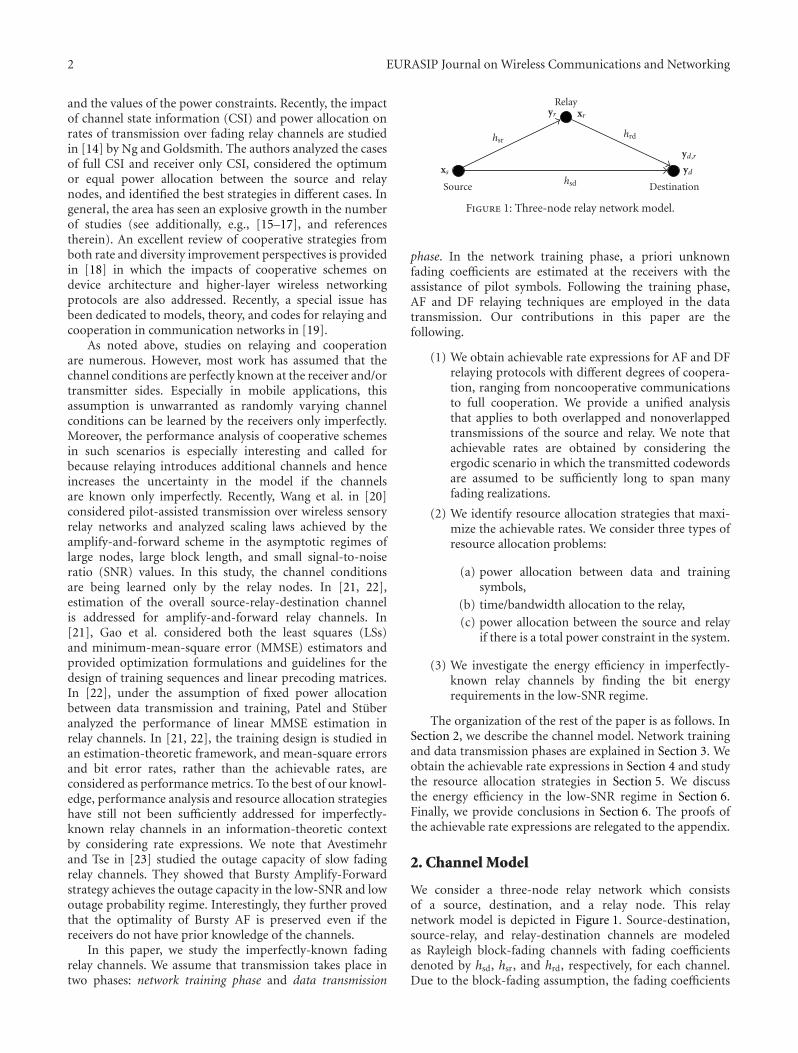
Figure 1: Three-node relay network model.
phase. In the network training phase, a priori unknownfading coefficients are estimated at the receivers with theassistance of pilot symbols. Following the training phase,AF and DF relaying techniques are employed in the datatransmission. Our contributions in this paper are thefollowing.
(1) We obtain achievable rate expressions for AF and DFrelaying protocols with different degrees of coopera-tion, ranging from noncooperative communicationsto full cooperation. We provide a unified analysisthat applies to both overlapped and nonoverlappedtransmissions of the source and relay. We note thatachievable rates are obtained by considering theergodic scenario in which the transmitted codewordsare assumed to be sufficiently long to span manyfading realizations.
(2) We identify resource allocation strategies that maxi-mize the achievable rates. We consider three types ofresource allocation problems:
(a) power allocation between data and trainingsymbols,
(b) time/bandwidth allocation to the relay,
(c) power allocation between the source and relayif there is a total power constraint in the system.
(3) We investigate the energy efficiency in imperfectly-known relay channels by finding the bit energyrequirements in the low-SNR regime.
The organization of the rest of the paper is as follows. InSection 2, we describe the channel model. Network trainingand data transmission phases are explained in Section 3. Weobtain the achievable rate expressions in Section 4 and studythe resource allocation strategies in Section 5. We discussthe energy efficiency in the low-SNR regime in Section 6.Finally, we provide conclusions in Section 6. The proofs ofthe achievable rate expressions are relegated to the appendix.
2. Channel Model
We consider a three-node relay network which consistsof a source, destination, and a relay node. This relaynetwork model is depicted in Figure 1. Source-destination,source-relay, and relay-destination channels are modeledas Rayleigh block-fading channels with fading coefficientsdenoted by hsd, hsr, and hrd, respectively, for each channel.Due to the block-fading assumption, the fading coefficients
EURASIP Journal on Wireless Communications and Networking 3
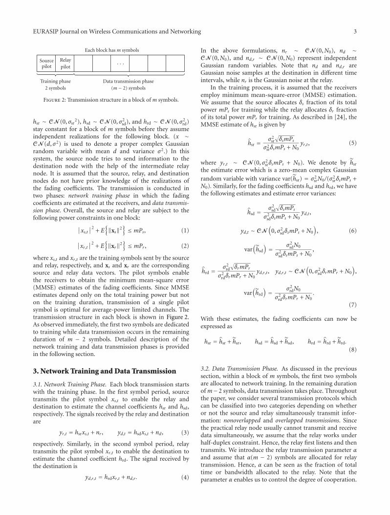
Sourcepilot
Relaypilot
Training phase2 symbols
Each block has m symbols
· · ·
Data transmission phase(m− 2) symbols
Figure 2: Transmission structure in a block of m symbols.
hsr ∼ CN (0, σsr2), hsd ∼ CN (0, σ2
sd), and hrd ∼ CN (0, σ2rd)
stay constant for a block of m symbols before they assumeindependent realizations for the following block. (x ∼CN (d, σ2) is used to denote a proper complex Gaussianrandom variable with mean d and variance σ2.) In thissystem, the source node tries to send information to thedestination node with the help of the intermediate relaynode. It is assumed that the source, relay, and destinationnodes do not have prior knowledge of the realizations ofthe fading coefficients. The transmission is conducted intwo phases: network training phase in which the fadingcoefficients are estimated at the receivers, and data transmis-sion phase. Overall, the source and relay are subject to thefollowing power constraints in one block:
∣∣xs,t
∣∣2 + E
{
‖xs‖2}
≤ mPs, (1)
∣∣xr,t
∣∣2 + E
{
‖xr‖2}
≤ mPr , (2)
where xs,t and xr,t are the training symbols sent by the sourceand relay, respectively, and xs and xr are the correspondingsource and relay data vectors. The pilot symbols enablethe receivers to obtain the minimum mean-square error(MMSE) estimates of the fading coefficients. Since MMSEestimates depend only on the total training power but noton the training duration, transmission of a single pilotsymbol is optimal for average-power limited channels. Thetransmission structure in each block is shown in Figure 2.As observed immediately, the first two symbols are dedicatedto training while data transmission occurs in the remainingduration of m − 2 symbols. Detailed description of thenetwork training and data transmission phases is providedin the following section.
3. Network Training and Data Transmission
3.1. Network Training Phase. Each block transmission startswith the training phase. In the first symbol period, sourcetransmits the pilot symbol xs,t to enable the relay anddestination to estimate the channel coefficients hsr and hsd,respectively. The signals received by the relay and destinationare
yr,t = hsrxs,t + nr , yd,t = hsdxs,t + nd, (3)
respectively. Similarly, in the second symbol period, relaytransmits the pilot symbol xr,t to enable the destination toestimate the channel coefficient hrd. The signal received bythe destination is
yd,r,t = hrdxr,t + nd,r . (4)
In the above formulations, nr ∼ CN (0,N0), nd ∼CN (0,N0), and nd,r ∼ CN (0,N0) represent independentGaussian random variables. Note that nd and nd,r areGaussian noise samples at the destination in different timeintervals, while nr is the Gaussian noise at the relay.
In the training process, it is assumed that the receiversemploy minimum mean-square-error (MMSE) estimation.We assume that the source allocates δs fraction of its totalpower mPs for training while the relay allocates δr fractionof its total power mPr for training. As described in [24], theMMSE estimate of hsr is given by
hsr = σ2sr
√
δsmPsσ2
srδsmPs + N0yr,t, (5)
where yr,t ∼ CN (0, σ2srδsmPs + N0). We denote by hsr
the estimate error which is a zero-mean complex Gaussian
random variable with variance var(hsr) = σ2srN0/(σ2
srδsmPs +N0). Similarly, for the fading coefficients hsd and hrd, we havethe following estimates and estimate error variances:
hsd =σ2
sd
√
δsmPsσ2
sdδsmPs + N0yd,t,
yd,t ∼ CN(
0, σ2sdδsmPs + N0
)
,
var(
hsd
)
= σ2sdN0
σ2sdδsmPs + N0
,
(6)
hrd =σ2
rd
√
δrmPrσ2
rdδrmPr + N0yd,r,t, yd,r,t ∼ CN
(
0, σ2rdδrmPr + N0
)
,
var(
hrd
)
= σ2rdN0
σ2rdδrmPr + N0
.
(7)
With these estimates, the fading coefficients can now beexpressed as
hsr = hsr + hsr, hsd = hsd + hsd, hrd = hrd + hrd.(8)
3.2. Data Transmission Phase. As discussed in the previoussection, within a block of m symbols, the first two symbolsare allocated to network training. In the remaining durationof m−2 symbols, data transmission takes place. Throughoutthe paper, we consider several transmission protocols whichcan be classified into two categories depending on whetheror not the source and relay simultaneously transmit infor-mation: nonoverlapped and overlapped transmissions. Sincethe practical relay node usually cannot transmit and receivedata simultaneously, we assume that the relay works underhalf-duplex constraint. Hence, the relay first listens and thentransmits. We introduce the relay transmission parameter αand assume that α(m − 2) symbols are allocated for relaytransmission. Hence, α can be seen as the fraction of totaltime or bandwidth allocated to the relay. Note that theparameter α enables us to control the degree of cooperation.
4 EURASIP Journal on Wireless Communications and Networking
In nonoverlapped transmission protocol, source and relaytransmit over nonoverlapping intervals. Therefore, sourcetransmits over a duration of (1 − α)(m − 2) symbols andbecomes silent as the relay transmits. On the other hand,in overlapped transmission protocol, source transmits all thetime and sends m− 2 symbols in each block.
We assume that the source transmits at a per-symbolpower level of Ps1 when the relay is silent, and Ps2 whenthe relay is in transmission. Clearly, in nonoverlapped mode,Ps2 = 0. On the other hand, in overlapped transmission, weassume Ps1 = Ps2. Noting that the total power available afterthe transmission of the pilot symbol is (1 − δs)mPs, we canwrite
(1− α)(m− 2)Ps1 + α(m− 2)Ps2 = (1− δs)mPs. (9)
The above assumptions imply that power for data trans-mission is equally distributed over the symbols duringthe transmission periods. Hence, in nonoverlapped andoverlapped modes, the symbol powers are Ps1 = ((1 −δs)mPs)/((1−α)(m−2)) and Ps1 = Ps2 = ((1−δs)mPs)/(m−2), respectively. Furthermore, we assume that the power ofeach symbol transmitted by the relay node is Pr1, whichsatisfies, similarly as above,
α(m− 2)Pr1 = (1− δr)mPr. (10)
Next, we provide detailed descriptions of nonoverlapped andoverlapped cooperative transmission schemes.
3.2.1. Nonoverlapped Transmission. We first consider the twosimplest cooperative protocols: nonoverlapped AF where therelay amplifies the received signal and forwards it to thedestination, and nonoverlapped DF with repetition codingwhere the relay decodes the message, reencodes it usingthe same codebook as the source, and forwards it. In theseprotocols, since the relay either amplifies the received signalor decodes it but uses the same codebook as the sourcewhen forwarding, source and relay should be allocatedequal time slots in the cooperation phase. Therefore, beforecooperation starts, we initially have direct transmission fromthe source to the destination without any aid from therelay over a duration of (1 − 2α)(m − 2) symbols. In thisphase, source sends the (1 − 2α)(m − 2)-dimensional datavector xs1 and the received signal at the destination is givenby
yd1 = hsdxs1 + nd1. (11)
Subsequently, cooperative transmission starts. At first, thesource transmits the α(m − 2)-dimensional data vectorxs2 which is received at the the relay and the destination,respectively, as
yr = hsrxs2 + nr , yd2 = hsdxs2 + nd2. (12)
In (11) and (12), nd1 and nd2 are independent Gaussian noisevectors composed of independent and identically distributed(i.i.d.), circularly symmetric, zero-mean complex Gaussianrandom variables with variance N0, modeling the additivebackground noise at the transmitter in different transmission
phases. Similarly, nr is a Gaussian noise vector at the relay,whose components are i.i.d. zero-mean Gaussian randomvariables with variance N0. For compact representation, wedenote the overall source data vector by xs = [xTs1 xTs2]T andthe signal received at the destination directly from the sourceby yd = [yTd1 yTd2]T where T denotes the transpose operation.After completing its transmission, the source becomes silent,and the relay transmits an α(m − 2)-dimensional symbolvector xr which is generated from the previously received yr[6, 7]. Now, the destination receives
yd,r = hrdxr + nd,r . (13)
After substituting the estimate expressions in (8) into (11)–(13), we have
yd1 = hsdxs1 + hsdxs1 + nd1,
yr = hsrxs2 + hsrxs2 + nr ,
yd2 = hsdxs2 + hsdxs2 + nd2,
(14)
yd,r = hrdxr + hrdxr + nd,r . (15)
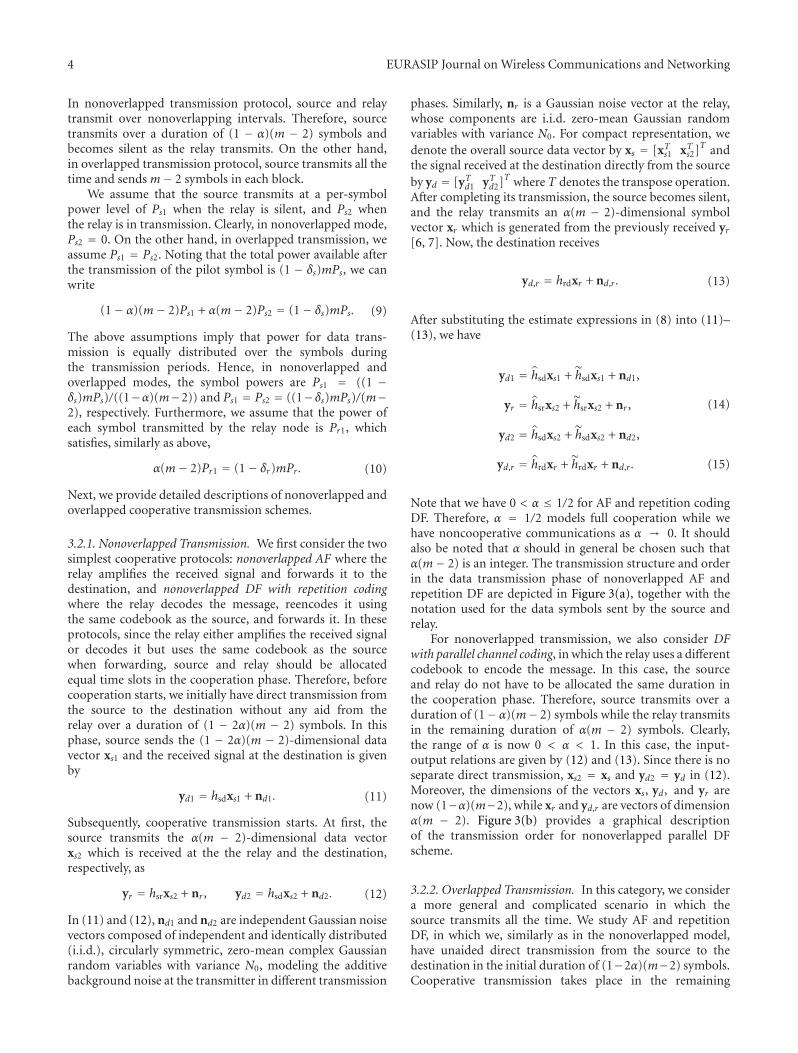
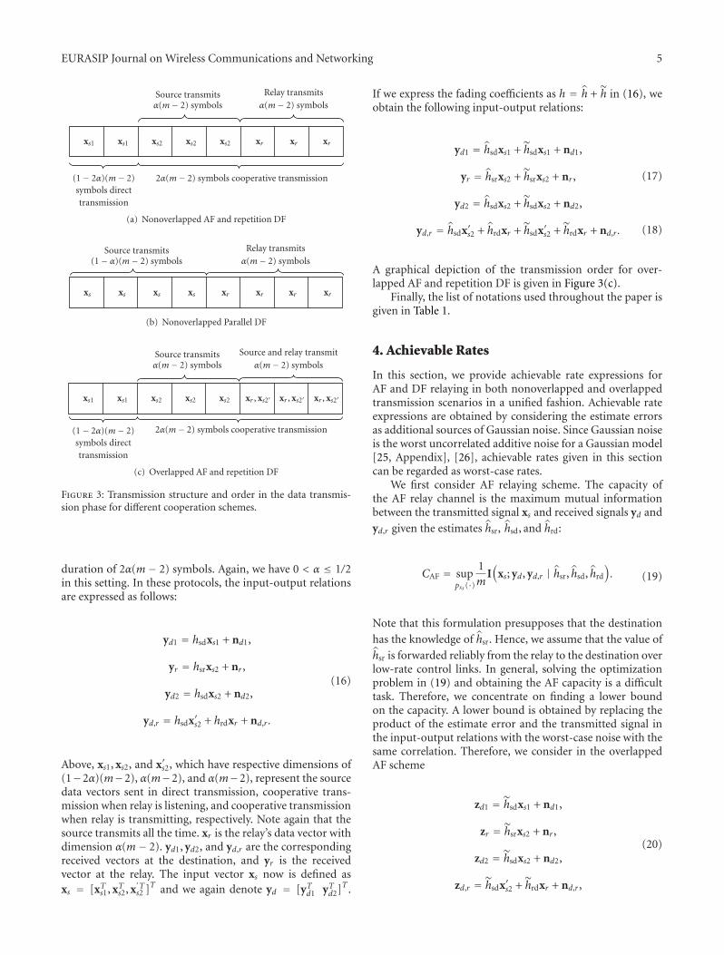
Note that we have 0 < α ≤ 1/2 for AF and repetition codingDF. Therefore, α = 1/2 models full cooperation while wehave noncooperative communications as α → 0. It shouldalso be noted that α should in general be chosen such thatα(m− 2) is an integer. The transmission structure and orderin the data transmission phase of nonoverlapped AF andrepetition DF are depicted in Figure 3(a), together with thenotation used for the data symbols sent by the source andrelay.
For nonoverlapped transmission, we also consider DFwith parallel channel coding, in which the relay uses a differentcodebook to encode the message. In this case, the sourceand relay do not have to be allocated the same duration inthe cooperation phase. Therefore, source transmits over aduration of (1− α)(m− 2) symbols while the relay transmitsin the remaining duration of α(m − 2) symbols. Clearly,the range of α is now 0 < α < 1. In this case, the input-output relations are given by (12) and (13). Since there is noseparate direct transmission, xs2 = xs and yd2 = yd in (12).Moreover, the dimensions of the vectors xs, yd, and yr arenow (1−α)(m−2), while xr and yd,r are vectors of dimensionα(m − 2). Figure 3(b) provides a graphical descriptionof the transmission order for nonoverlapped parallel DFscheme.
3.2.2. Overlapped Transmission. In this category, we considera more general and complicated scenario in which thesource transmits all the time. We study AF and repetitionDF, in which we, similarly as in the nonoverlapped model,have unaided direct transmission from the source to thedestination in the initial duration of (1−2α)(m−2) symbols.Cooperative transmission takes place in the remaining
EURASIP Journal on Wireless Communications and Networking 5
Source transmitsα(m− 2) symbols
Relay transmits
α(m− 2) symbols
xs1 xs1 xs2 xs2 xs2 xr xr xr
(1− 2α)(m− 2)symbols directtransmission
2α(m− 2) symbols cooperative transmission
(a) Nonoverlapped AF and repetition DF
Source transmits(1− α)(m− 2) symbols
Relay transmits
α(m− 2) symbols
xs xs xs xs xr xr xr xr
(b) Nonoverlapped Parallel DF
Source transmitsα(m− 2) symbols
Source and relay transmit
α(m− 2) symbols
xs1 xs1 xs2 xs2 xs2 xr , xs2′ xr , xs2′ xr , xs2′
(1− 2α)(m− 2)symbols directtransmission
2α(m− 2) symbols cooperative transmission
(c) Overlapped AF and repetition DF
Figure 3: Transmission structure and order in the data transmis-sion phase for different cooperation schemes.
duration of 2α(m − 2) symbols. Again, we have 0 < α ≤ 1/2in this setting. In these protocols, the input-output relationsare expressed as follows:
yd1 = hsdxs1 + nd1,
yr = hsrxs2 + nr ,
yd2 = hsdxs2 + nd2,
yd,r = hsdx′s2 + hrdxr + nd,r .
(16)
Above, xs1, xs2, and x′s2, which have respective dimensions of(1−2α)(m−2), α(m−2), and α(m−2), represent the sourcedata vectors sent in direct transmission, cooperative trans-mission when relay is listening, and cooperative transmissionwhen relay is transmitting, respectively. Note again that thesource transmits all the time. xr is the relay’s data vector withdimension α(m− 2). yd1, yd2, and yd,r are the correspondingreceived vectors at the destination, and yr is the receivedvector at the relay. The input vector xs now is defined asxs = [xTs1, xTs2, x
′Ts2 ]T and we again denote yd = [yTd1 yTd2]T .
If we express the fading coefficients as h = h + h in (16), weobtain the following input-output relations:
yd1 = hsdxs1 + hsdxs1 + nd1,
yr = hsrxs2 + hsrxs2 + nr ,
yd2 = hsdxs2 + hsdxs2 + nd2,
(17)
yd,r = hsdx′s2 + hrdxr + hsdx′s2 + hrdxr + nd,r . (18)
A graphical depiction of the transmission order for over-lapped AF and repetition DF is given in Figure 3(c).
Finally, the list of notations used throughout the paper isgiven in Table 1.
4. Achievable Rates
In this section, we provide achievable rate expressions forAF and DF relaying in both nonoverlapped and overlappedtransmission scenarios in a unified fashion. Achievable rateexpressions are obtained by considering the estimate errorsas additional sources of Gaussian noise. Since Gaussian noiseis the worst uncorrelated additive noise for a Gaussian model[25, Appendix], [26], achievable rates given in this sectioncan be regarded as worst-case rates.
We first consider AF relaying scheme. The capacity ofthe AF relay channel is the maximum mutual informationbetween the transmitted signal xs and received signals yd and
yd,r given the estimates hsr, hsd, and hrd:
CAF = suppxs (·)
1mI(
xs; yd, yd,r | hsr, hsd, hrd
)
. (19)
Note that this formulation presupposes that the destination
has the knowledge of hsr. Hence, we assume that the value of
hsr is forwarded reliably from the relay to the destination overlow-rate control links. In general, solving the optimizationproblem in (19) and obtaining the AF capacity is a difficulttask. Therefore, we concentrate on finding a lower boundon the capacity. A lower bound is obtained by replacing theproduct of the estimate error and the transmitted signal inthe input-output relations with the worst-case noise with thesame correlation. Therefore, we consider in the overlappedAF scheme
zd1 = hsdxs1 + nd1,
zr = hsrxs2 + nr ,
zd2 = hsdxs2 + nd2,
zd,r = hsdx′s2 + hrdxr + nd,r ,
(20)

6 EURASIP Journal on Wireless Communications and Networking
Table 1: List of notations.
hsd Source-destination channel fading coefficient
hsr Relay-destination channel fading coefficient
hrd Relay-destination channel fading coefficient
h· Estimate of the fading coefficient h·h· Error in the estimate of the fading coefficient h·σ2 Variance of random variables
N0 Variance of Gaussian random variables due to thermal noise
m Number of symbols in each block
mPs Total average power of the source in each block of m symbols
mPr Total average power of the relay in each block of m symbols
δs Fraction of total power allocated to training by the source
δr Fraction of total power allocated to training by the relay
xs,t Pilot symbol sent by the source
xr,t Pilot symbol sent by the relay
nd Additive Gaussian noise at the destination in the interval in which the source pilot symbol is sent
nr Additive Gaussian noise at the relay in the interval in which the source pilot symbol is sent
nd,r Additive Gaussian noise at the destination in the interval in which the relay pilot symbol is sent
yd,t Received signal at the destination in the interval in which the source pilot symbol is sent
yd,t Received signal at the relay in the interval in which the source pilot symbol is sent
yd,r,t Received signal at the destination in the interval in which the relay pilot symbol is sent
Ps1 Power of each source symbol sent in the interval in which the relay is not transmitting
Ps2 Power of each source symbol sent in the interval in which the relay is transmitting
Pr1 Power of each relay symbol
α Fraction of time/bandwidth allocated to the relay
xs1 (1− 2α)(m− 2)-dimensional data vector sent by the source in the noncooperative transmission mode
xs2Data vector sent by the source when the relay is listening. The dimension is α(m− 2) for AF and repetition DF, and(1− α)(m− 2) for parallel DF
x′s2 α(m− 2)-dimensional data vector sent by the source when the relay is transmitting
xr α(m− 2)-dimensional data vector sent by the relay
nd1 (1− 2α)(m− 2)-dimensional noise vector at the destination in the noncooperative transmission mode
nd2Noise vector at the destination in the interval when the relay is listening. The dimension is α(m− 2) for AF and repetition DF,and (1− α)(m− 2) for parallel DF
nd,r α(m− 2)-dimensional noise vector at the destination in the interval when the relay is transmitting
nr Noise vector at the relay. The dimension is α(m− 2) for AF and repetition DF, and (1− α)(m− 2) for parallel DF
yd1 (1− 2α)(m− 2)-dimensional received vector at the destination in the noncooperative transmission mode
yd2Received vector at the destination in the interval when the relay is listening. The dimension is α(m− 2) for AF and repetitionDF, and (1− α)(m− 2) for parallel DF
yd,r α(m− 2)-dimensional received vector at the destination in the interval when the relay is transmitting
yr Received vector at the relay. The dimension is α(m− 2) for AF and repetition DF, and (1− α)(m− 2) for parallel DF
as noise vectors with covariance matrices
E{
zd1z†d1
}
= σ2zd1I = σ2
hsdE{
xs1x†s1
}
+ N0I,
E{
zrz†r}
= σ2zr I = σ2
hsrE{
xs2x†s2
}
+ N0I,(21)
E{
zd2z†d2
}
= σ2zd2I = σ2
hsdE{
xs2x†s2
}
+ N0I,
E{
zd,rz†d,r
}
= σ2zd,rI = σ2
hsdE{
x′s2x′†s2
}
+ σ2hrdE{
xrx†r}
+ N0I.
(22)
Above, x† denotes the conjugate transpose of the vector x.Note that the expressions for the nonoverlapped AF scheme
can be obtained as a special case of (20)–(22) by settingx′s2 = 0.
An achievable rate expression RAF is obtained by solvingthe following optimization problem which requires findingthe worst-case noise:
CAF � RAF
= infpzd1
(·),pzr (·),pzd2(·),pzd,r
(·)
× suppxs (·)
1mI(
xs; yd, yd,r | hsr, hsd, hrd
)
.
(23)
EURASIP Journal on Wireless Communications and Networking 7
The following results provide a general formula for RAF,which applies to both nonoverlapped and overlapped trans-mission scenarios.
Theorem 1. An achievable rate for AF transmission scheme isgiven by
RAF
= 1mEwsd,wrd,wsr
×
⎧
⎪⎨
⎪⎩
(1− 2α)(m− 2) log
⎛
⎜⎝1 +
Ps1∣∣∣hsd
∣∣∣
2
σ2zd1
⎞
⎟⎠ + (m− 2)
× α log
⎛
⎜⎝1 +
Ps1∣∣∣hsd
∣∣∣
2
σ2zd2
+ f
⎛
⎜⎝
Ps1∣∣∣hsr
∣∣∣
2
σ2zr
,Pr1
∣∣∣hrd
∣∣∣
2
σ2zd,r
⎞
⎟⎠
+ q
⎛
⎜⎝
Ps1∣∣∣hsd
∣∣∣
2
σ2zd2
,Ps2
∣∣∣hsd
∣∣∣
2
σ2zd,r
,
Ps1∣∣∣hsr
∣∣∣
2
σ2zr
,Pr1
∣∣∣hrd
∣∣∣
2
σ2zd,r
⎞
⎟⎠
⎞
⎟⎠
⎫
⎪⎬
⎪⎭
,
(24)
where f (·) and q(·) are defined as f (x, y) = xy/(1 + x + y)and q(a, b, c,d) = ((1 + a)b(1 + c))/(1 + c + d). Furthermore,
Ps1∣∣∣hsd
∣∣∣
2
σ2zd1
=Ps1
∣∣∣hsd
∣∣∣
2
σ2zd2
,
= Ps1δsmPsσ4sd
Ps1σ2sdN0 +
(
σ2sdδsmPs + N0
)
N0
|wsd|2,
(25)
Ps1∣∣∣hsr
∣∣∣
2
σ2zr
= Ps1δsmPsσ4sr
Ps1σ2srN0 +
(
σ2srδsmPs + N0
)
N0|wsr|2, (26)
Pr1
∣∣∣h2
rd
∣∣∣
σ2zd,r
=Pr1δrmPrσ
4rd
(
σ2sdδsmPs + N0
)
|wrd|2
X, (27)
Ps2∣∣∣h2
sd
∣∣∣
σ2zd,r
=Ps2δsmPsσ
4sd
(
σ2rdδrmPr + N0
)
|wsd|2
X, (28)
where X denotes Ps2σ2sdN0(σ2
rdδrmPr + N0) + Pr1σ2rdN0
× (σ2sdδsmPs + N0) + N0(σ2
sdδsmPs + N0)(σ2rdδrmPr + N0). In
the above equations and henceforth, wsr ∼ CN (0, 1), wsd ∼CN (0, 1), and wrd ∼ CN (0, 1) denote independent, standardGaussian random variables. The above formulation applies toboth overlapped and nonoverlapped cases. Recalling (9), if oneassumes in (24)–(28) that
Ps1 = (1− δs)mPs(m− 2)(1− α)
, Ps2 = 0, (29)
one obtains the achievable rate expression for the nonover-lapped AF scheme. Note that if Ps2 = 0, the functionq(·, ·, ·, ·) = 0 in (24). For overlapped AF, one has
Ps1 = Ps2 = (1− δs)mPsm− 2
. (30)
Moreover, one knows from (10) that
Pr1 = (1− δr)mPr(m− 2)α
. (31)
Proof. See Appendix A.
Next, we consider DF relaying scheme. In DF, thereare two different coding approaches [7], namely, repetitioncoding and parallel channel coding. We first consider repeti-tion channel coding scheme. The following result providesachievable rate expressions for both nonoverlapped andoverlapped transmission scenarios.
Theorem 2. An achievable rate expression for DF withrepetition channel coding transmission scheme is given by
RDFr = (1− 2α)(m− 2)m
Ewsd
⎧
⎪⎨
⎪⎩
log
⎛
⎜⎝1 +
Ps1∣∣∣hsd
∣∣∣
2
σ2zd1
⎞
⎟⎠
⎫
⎪⎬
⎪⎭
+(m− 2)α
mmin{I1, I2},
(32)
where
I1 = Ewsr
⎧
⎪⎨
⎪⎩
log
⎛
⎜⎝1 +
Ps1∣∣∣hsr
∣∣∣
2
σ2zr
⎞
⎟⎠
⎫
⎪⎬
⎪⎭
, (33)
I2 = Ewsd,wrd
×
⎧
⎪⎨
⎪⎩
log
⎛
⎜⎝1 +
Ps1∣∣∣hsd
∣∣∣
2
σ2zd2
+Pr1
∣∣∣hrd
∣∣∣
2
σ2zd,r
+Ps2
∣∣∣hsd
∣∣∣
2
σ2zd,r
+Ps1
∣∣∣hsd
∣∣∣
2
σ2zd2
Ps2∣∣∣hsd
∣∣∣
2
σ2zd,r
⎞
⎟⎠
⎫
⎪⎬
⎪⎭
.
(34)
(Ps1|hsd|2)/(σ2
zd1),(Ps1|hsd|
2)/(σ2
zd2), (Ps1|hsr|
2)/(σ2
zr ), (Ps2|hsd|2)/
(σ2zd,r
), (Pr1
∣∣∣hrd
∣∣∣
2)/(σ2
zd,r) have the same expressions as in (25)–
(28). Ps1,Ps2, and Pr1 are given in (29)–(31).
Proof. See Appendix B.
Finally, we consider DF with parallel channel coding andassume that nonoverlapped transmission scheme is adopted.From [13, Equation ( 6)], we note that an achievable rateexpression is given by
min{
(1− α)I(
xs; yr | hsr
)
,
(1− α)I(
xs; yd | hsd
)
+ αI(
xr ; yd,r | hrd
)}
.(35)
8 EURASIP Journal on Wireless Communications and Networking
151050
σrd
Pr = 0.1Pr = 1Pr = 5
Pr = 20Pr = 200
0
0.2
0.25
0.3
0.35
0.4
0.45
0.5
δ r
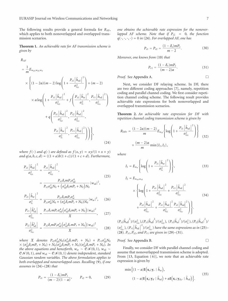
Figure 4: δr versus σrd for different values of Pr when m = 50.
Note that we do not have separate direct transmission inthis relaying scheme. Using similar methods as in the proofsof Theorems 1 and 2, we obtain the following result. Theproof is omitted to avoid repetition.
Theorem 3. An achievable rate of nonoverlapped DF withparallel channel coding scheme is given by
RDFp = min
⎧
⎪⎨
⎪⎩
(1− α)(m− 2)m
Ewsr
⎧
⎪⎨
⎪⎩
log
⎛
⎜⎝1 +
Ps1∣∣∣hsr
∣∣∣
2
σ2zr
⎞
⎟⎠
⎫
⎪⎬
⎪⎭
,
(1− α)(m− 2)m
Ewsd
⎧
⎪⎨
⎪⎩
log
⎛
⎜⎝1 +
Ps1∣∣∣hsd
∣∣∣
2
σ2zd2
⎞
⎟⎠
⎫
⎪⎬
⎪⎭
+α(m− 2)
mEwrd
⎧
⎪⎨
⎪⎩
log
⎛
⎜⎝1 +
Pr1
∣∣∣hrd
∣∣∣
2
σ2zd,r
⎞
⎟⎠
⎫
⎪⎬
⎪⎭
⎫
⎪⎬
⎪⎭
,
(36)
where (Ps1∣∣∣hsd
∣∣∣
2)/(σ2
zd2), (Ps1
∣∣∣hsr
∣∣∣
2)/(σ2
zr ), and (Pr1
∣∣∣hrd
∣∣∣
2)/
(σ2zd,r
) are given in (25)–(27) with Ps1 and Pr1 defined in (29)
and (31).
5. Resource Allocation Strategies
Having obtained achievable rate expressions in Section 4,we now identify resource allocation strategies that maximizethese rates. We consider three resource allocation problems:(1) power allocation between training and data symbols,(2) time/bandwidth allocation to the relay, and (3) powerallocation between the source and relay under a total powerconstraint.
We first study how much power should be allocatedfor channel training. In nonoverlapped AF, it can be seen
00.2
0.40.6
0.81
δr00.2
0.40.6
0.810
1
2
3
4
Ach
ieva
ble
rate
s(b
its/
sym
bol)
δs
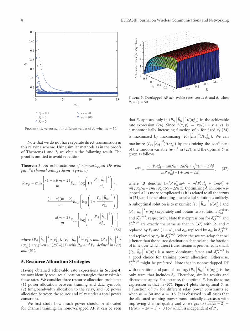
Figure 5: Overlapped AF achievable rates versus δs and δr whenPs = Pr = 50.
that δr appears only in (Pr1
∣∣∣hrd
∣∣∣
2)/(σ2
zd,r) in the achievable
rate expression (24). Since f (x, y) = xy/(1 + x + y) isa monotonically increasing function of y for fixed x, (24)
is maximized by maximizing (Pr1
∣∣∣hrd
∣∣∣
2)/(σ2
zd,r). We can
maximize (Pr1
∣∣∣hrd
∣∣∣
2)/(σ2
zd,r) by maximizing the coefficient
of the random variable |wrd|2 in (27), and the optimal δr isgiven as follows:
δoptr =
−mPrσ2rd − αmN0 + 2αN0 +
√
α(m− 2)P
mPrσ2rd(−1 + αm− 2α)
, (37)
where P denotes (m2Prσ2rdαN0 + m2P2
r σ4rd + αmN2
0 +mPrσ
2rdN0−2mPrσ
2rdαN0−2N0α). Optimizing δs in nonover-
lapped AF is more complicated as it is related to all the termsin (24), and hence obtaining an analytical solution is unlikely.
A suboptimal solution is to maximize (Ps1∣∣∣hsd
∣∣∣
2)/(σ2
zd1) and
(Ps1∣∣∣hsr
∣∣∣
2)/(σ2
zr ) separately and obtain two solutions δsubopts,1
and δsubopts,2 , respectively. Note that expressions for δ
subopts,1 and
δsubopts,2 are exactly the same as that in (37) with Pr and α
replaced by Ps and (1 − α), and σrd replaced by σsd in δsubopts,1
and replaced by σsr in δsubopts,2 . When the source-relay channel
is better than the source-destination channel and the fractionof time over which direct transmission is performed is small,
(Ps1∣∣∣hsr
∣∣∣
2)/(σ2
zr ) is a more dominant factor and δsubopts,2 is
a good choice for training power allocation. Otherwise,
δsubopts,1 might be preferred. Note that in nonoverlapped DF
with repetition and parallel coding, (Pr1
∣∣∣hrd
∣∣∣
2)/(σ2
zd,r) is the
only term that includes δr . Therefore, similar results anddiscussions apply. For instance, the optimal δr has the sameexpression as that in (37). Figure 4 plots the optimal δr asa function of σrd for different relay power constraints Prwhen m = 50 and α = 0.5. It is observed in all cases thatthe allocated training power monotonically decreases withimproving channel quality and converges to (
√
α(m− 2) −1)/(αm− 2α− 1) ≈ 0.169 which is independent of Pr .
EURASIP Journal on Wireless Communications and Networking 9
00.2
0.40.6
0.81
δr0
0.5
1
δs
0
0.1
0.2
0.3
0.4
Ach
ieva
ble
rate
s(b
its/
sym
bol)
Figure 6: Overlapped AF achievable rates versus δs and δr whenPs = Pr = 0.5
In overlapped transmission schemes, both δs and δrappear in more than one term in the achievable rate expres-sions. Therefore, we resort to numerical results to identify theoptimal values. Figures 5 and 6 plot the achievable rates as afunction of δs and δr for overlapped AF. In both figures, wehave assumed that σsd = 1, σsr = 2, σrd = 1,m = 50, andN0 = 1, α = 0.5. While Figure 5 considers high SNRs(Ps = 50 and Pr = 50), we assume that Ps = 0.5 andPr = 0.5 in Figure 6. In Figure 5, we observe that increasingδs will increase achievable rate until δs ≈ 0.1. Further increasein δs decreases the achievable rates. On the other hand,rates always increase with increasing δr , leaving less and lesspower for data transmission by the relay. This indicates thatcooperation is not beneficial in terms of achievable ratesand direct transmission should be preferred. On the otherhand, in the low-power regime considered in Figure 6, theoptimal values of δs and δr are approximately 0.18 and 0.32,respectively. Hence, the relay in this case helps to improve therates.
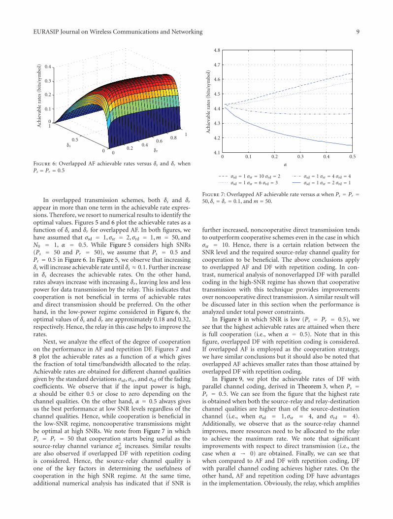
Next, we analyze the effect of the degree of cooperationon the performance in AF and repetition DF. Figures 7 and8 plot the achievable rates as a function of α which givesthe fraction of total time/bandwidth allocated to the relay.Achievable rates are obtained for different channel qualitiesgiven by the standard deviations σsd, σsr, and σrd of the fadingcoefficients. We observe that if the input power is high,α should be either 0.5 or close to zero depending on thechannel qualities. On the other hand, α = 0.5 always givesus the best performance at low SNR levels regardless of thechannel qualities. Hence, while cooperation is beneficial inthe low-SNR regime, noncooperative transmissions mightbe optimal at high SNRs. We note from Figure 7 in whichPs = Pr = 50 that cooperation starts being useful as thesource-relay channel variance σ2
sr increases. Similar resultsare also observed if overlapped DF with repetition codingis considered. Hence, the source-relay channel quality isone of the key factors in determining the usefulness ofcooperation in the high SNR regime. At the same time,additional numerical analysis has indicated that if SNR is
0.50.40.30.20.10
α
σsd = 1 σsr = 10 σrd = 2σsd = 1 σsr = 6 σrd = 3
σsd = 1 σsr = 4 σrd = 4σsd = 1 σsr = 2 σrd = 1
4.1
4.2
4.3
4.4
4.5
4.6
4.7
4.8
Ach
ieva
ble
rate
s(b
its/
sym
bol)
Figure 7: Overlapped AF achievable rate versus α when Ps = Pr =50, δs = δr = 0.1, and m = 50.
further increased, noncooperative direct transmission tendsto outperform cooperative schemes even in the case in whichσsr = 10. Hence, there is a certain relation between theSNR level and the required source-relay channel quality forcooperation to be beneficial. The above conclusions applyto overlapped AF and DF with repetition coding. In con-trast, numerical analysis of nonoverlapped DF with parallelcoding in the high-SNR regime has shown that cooperativetransmission with this technique provides improvementsover noncooperative direct transmission. A similar result willbe discussed later in this section when the performance isanalyzed under total power constraints.
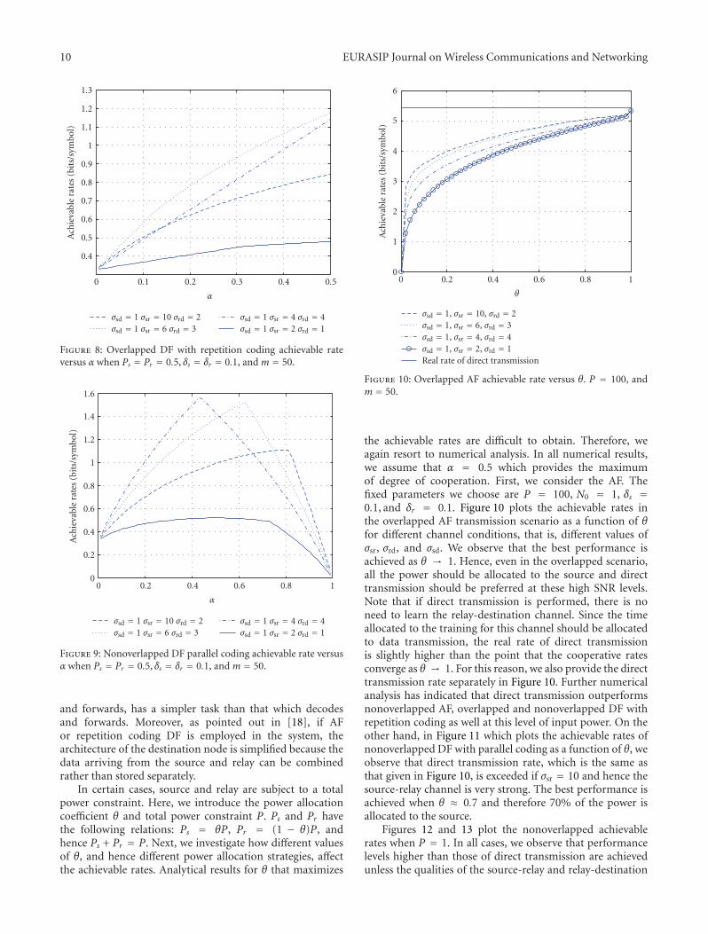
In Figure 8 in which SNR is low (Ps = Pr = 0.5), wesee that the highest achievable rates are attained when thereis full cooperation (i.e., when α = 0.5). Note that in thisfigure, overlapped DF with repetition coding is considered.If overlapped AF is employed as the cooperation strategy,we have similar conclusions but it should also be noted thatoverlapped AF achieves smaller rates than those attained byoverlapped DF with repetition coding.
In Figure 9, we plot the achievable rates of DF withparallel channel coding, derived in Theorem 3, when Ps =Pr = 0.5. We can see from the figure that the highest rateis obtained when both the source-relay and relay-destinationchannel qualities are higher than of the source-destinationchannel (i.e., when σsd = 1, σsr = 4, and σrd = 4).Additionally, we observe that as the source-relay channelimproves, more resources need to be allocated to the relayto achieve the maximum rate. We note that significantimprovements with respect to direct transmission (i.e., thecase when α → 0) are obtained. Finally, we can see thatwhen compared to AF and DF with repetition coding, DFwith parallel channel coding achieves higher rates. On theother hand, AF and repetition coding DF have advantagesin the implementation. Obviously, the relay, which amplifies
10 EURASIP Journal on Wireless Communications and Networking
0.50.40.30.20.10
α
σsd = 1 σsr = 10 σrd = 2σsd = 1 σsr = 6 σrd = 3
σsd = 1 σsr = 4 σrd = 4σsd = 1 σsr = 2 σrd = 1
0.4
0.5
0.6
0.7
0.8
0.9
1
1.1
1.2
1.3
Ach
ieva
ble
rate
s(b
its/
sym
bol)
Figure 8: Overlapped DF with repetition coding achievable rateversus α when Ps = Pr = 0.5, δs = δr = 0.1, and m = 50.
10.80.60.40.20
α
σsd = 1 σsr = 10 σrd = 2σsd = 1 σsr = 6 σrd = 3
σsd = 1 σsr = 4 σrd = 4σsd = 1 σsr = 2 σrd = 1
0
0.2
0.4
0.6
0.8
1
1.2
1.4
1.6
Ach
ieva
ble
rate
s(b
its/
sym
bol)
Figure 9: Nonoverlapped DF parallel coding achievable rate versusα when Ps = Pr = 0.5, δs = δr = 0.1, and m = 50.
and forwards, has a simpler task than that which decodesand forwards. Moreover, as pointed out in [18], if AFor repetition coding DF is employed in the system, thearchitecture of the destination node is simplified because thedata arriving from the source and relay can be combinedrather than stored separately.
In certain cases, source and relay are subject to a totalpower constraint. Here, we introduce the power allocationcoefficient θ and total power constraint P. Ps and Pr havethe following relations: Ps = θP, Pr = (1 − θ)P, andhence Ps + Pr = P. Next, we investigate how different valuesof θ, and hence different power allocation strategies, affectthe achievable rates. Analytical results for θ that maximizes
10.80.60.40.20
θ
σsd = 1, σsr = 10, σrd = 2σsd = 1, σsr = 6, σrd = 3σsd = 1, σsr = 4, σrd = 4σsd = 1, σsr = 2, σrd = 1Real rate of direct transmission
0
1
2
3
4
5
6
Ach
ieva
ble
rate
s(b
its/
sym
bol)
Figure 10: Overlapped AF achievable rate versus θ. P = 100, andm = 50.
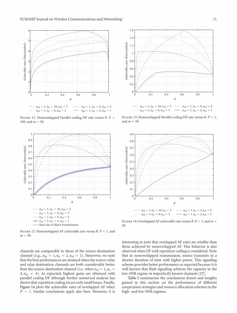
the achievable rates are difficult to obtain. Therefore, weagain resort to numerical analysis. In all numerical results,we assume that α = 0.5 which provides the maximumof degree of cooperation. First, we consider the AF. Thefixed parameters we choose are P = 100, N0 = 1, δs =0.1, and δr = 0.1. Figure 10 plots the achievable rates inthe overlapped AF transmission scenario as a function of θfor different channel conditions, that is, different values ofσsr, σrd, and σsd. We observe that the best performance isachieved as θ → 1. Hence, even in the overlapped scenario,all the power should be allocated to the source and directtransmission should be preferred at these high SNR levels.Note that if direct transmission is performed, there is noneed to learn the relay-destination channel. Since the timeallocated to the training for this channel should be allocatedto data transmission, the real rate of direct transmissionis slightly higher than the point that the cooperative ratesconverge as θ → 1. For this reason, we also provide the directtransmission rate separately in Figure 10. Further numericalanalysis has indicated that direct transmission outperformsnonoverlapped AF, overlapped and nonoverlapped DF withrepetition coding as well at this level of input power. On theother hand, in Figure 11 which plots the achievable rates ofnonoverlapped DF with parallel coding as a function of θ, weobserve that direct transmission rate, which is the same asthat given in Figure 10, is exceeded if σsr = 10 and hence thesource-relay channel is very strong. The best performance isachieved when θ ≈ 0.7 and therefore 70% of the power isallocated to the source.
Figures 12 and 13 plot the nonoverlapped achievablerates when P = 1. In all cases, we observe that performancelevels higher than those of direct transmission are achievedunless the qualities of the source-relay and relay-destination
EURASIP Journal on Wireless Communications and Networking 11
10.80.60.40.20
θ
σsd = 1, σsr = 10, σrd = 2σsd = 1, σsr = 6, σrd = 3
σsd = 1, σsr = 4, σrd = 4σsd = 1, σsr = 2, σrd = 1
0
1
2
3
4
5
6
Ach
ieva
ble
rate
s(b
its/
sym
bol)
Figure 11: Nonoverlapped Parallel coding DF rate versus θ. P =100, and m = 50.
10.80.60.40.20
θ
σsd = 1, σsr = 10, σrd = 2σsd = 1, σsr = 6, σrd = 3σsd = 1, σsr = 4, σrd = 4σsd = 1, σsr = 2, σrd = 1Real rate of direct transmission
0
0.1
0.2
0.3
0.4
0.5
0.6
0.7
0.8
0.9
1
Ach
ieva
ble
rate
s(b
its/
sym
bol)
Figure 12: Nonoverlapped AF achievable rate versus θ. P = 1, andm = 50.
channels are comparable to those of the source-destinationchannel (e.g., σsd = 1, σsr = 2, σrd = 1). Moreover, we notethat the best performances are attained when the source-relayand relay-destination channels are both considerably betterthan the source-destination channel (i.e., when σsd = 1, σsr =4, σrd = 4). As expected, highest gains are obtained withparallel coding DF although further numerical analysis hasshown that repetition coding incurs only small losses. Finally,Figure 14 plots the achievable rates of overlapped AF whenP = 1. Similar conclusions apply also here. However, it is
10.80.60.40.20
θ
σsd = 1, σsr = 10, σrd = 2σsd = 1, σsr = 6, σrd = 3
σsd = 1, σsr = 4, σrd = 4σsd = 1, σsr = 2, σrd = 1
0
0.2
0.4
0.6
0.8
1
1.2
1.4
1.6
Ach
ieva
ble
rate
s(b
its/
sym
bol)
Figure 13: Nonoverlapped Parallel coding DF rate versus θ. P = 1,and m = 50.
10.80.60.40.20
θ
σsd = 1 σsr = 10 σrd = 2σsd = 1 σsr = 6 σrd = 3
σsd = 1 σsr = 4 σrd = 4σsd = 1 σsr = 2 σrd = 1
0
0.1
0.2
0.3
0.4
0.5
0.6
0.7
0.8
0.9
Ach
ieva
ble
rate
s(b
its/
sym
bol)
Figure 14: Overlapped AF achievable rate versus θ. P = 1, and m =50.
interesting to note that overlapped AF rates are smaller thanthose achieved by nonoverlapped AF. This behavior is alsoobserved when DF with repetition coding is considered. Notethat in nonoverlapped transmission, source transmits in ashorter duration of time with higher power. This signalingscheme provides better performance as expected because it iswell known that flash signaling achieves the capacity in thelow-SNR regime in imperfectly known channels [27].
Table 2 summarizes the conclusions drawn and insightsgained in this section on the performance of differentcooperation strategies and resource allocation schemes in thehigh- and low-SNR regimes.
12 EURASIP Journal on Wireless Communications and Networking
Table 2
High-SNR Regime
(i) Cooperation employing overlapped AF or DF with repetition coding is beneficial only if the source-relaychannel quality is high enough. If this is not the case or SNR is very high, noncooperative direct transmissionshould be employed.
(ii) Cooperation using nonoverlapped DF with parallel coding provides improvements over the performance ofnoncooperative direct transmission and achieves higher rates than those attained by overlapped AF and DF withrepetition coding.
(iii) If the system is operating under total power constraints, all the power should be allocated to the source andhence direct transmission should be preferred over overlapped and nonoverlapped AF and overlapped andnonoverlapped DF with repetition coding.
(iv) Under total power constraints, only nonoverlapped DF with parallel coding outperforms noncooperativedirect transmission when the source-relay channel is strong.
Low-SNR Regime
(i) Cooperation is generally beneficial.
(ii) The strengths of both the source-relay and relay-destination channels are important factors.
(iii) Nonoverlapped DF with parallel coding achieves the highest performance levels. In general, nonoverlappedtransmission methods should be preferred. Also, DF provides higher gains over AF.
(iv) Under total power constraints, highest gains over noncooperative direct transmission are attained whenboth the source-relay and relay-destination channels are considerably stronger than the source-destinationchannel.
(v) Under total power constraints, noncooperative direct transmission should be preferred if the qualities ofboth the source-relay and relay-destination channels are comparable to that of the source-destination channel.
6. Energy Efficiency
Our analysis has shown that cooperative relaying is generallybeneficial in the low-power regime, resulting in higherachievable rates when compared to direct transmission. Inthis section, we provide an energy efficiency perspective andremark that care should be exercised when operating atvery low SNR values. The least amount of energy requiredto send one information bit reliably is given by Eb/N0 =SNR/(C(SNR)) where C(SNR) is the channel capacity inbits/symbol. (Note that Eb/N0 is the bit energy normalizedby the noise power spectral level N0.) In our setting, thecapacity will be replaced by the achievable rate expressionsand hence the resulting bit energy, denoted by E(b,U)/N0,provides the least amount of normalized bit energy valuesin the worst-case scenario and also serves as an upper boundon the achievable bit energy levels in the channel.
We note that in finding the bit energy values, we assumethat SNR = P/N0 where P = Pr + Ps is the total power. Thenext result provides the asymptotic behavior of the bit energyas SNR decreases to zero.
Theorem 4. The normalized bit energy in all relaying schemesgrows without bound as the signal-to-noise ratio decreases tozero, that is,
Eb,U
N0
∣∣∣∣R=0
= limSNR→ 0
SNRR(SNR)
= 1R(0)
= ∞. (38)
Proof. R(0) is the derivative of R with respect to SNR as SNR→ 0. The key point to prove this theorem is to show thatwhen SNR → 0, the mutual information decreases as SNR2,and hence R(0) = 0. This can be easily shown because when
P → 0, in all the terms, (Ps1∣∣∣hsd
∣∣∣
2)/(σ2
zd1), (Ps1
∣∣∣hsd
∣∣∣
2)/(σ2
zd2),
(Ps1∣∣∣hsr
∣∣∣
2)/(σ2
zr ), (Ps2∣∣∣hsd
∣∣∣
2)/(σ2
zd,r), and (Pr1
∣∣∣hrd
∣∣∣
2)/(σ2
zd,r)
in Theorems 1–3, the denominator goes to a constant while
10.80.60.40.20
SNR
m = 20m = 50
m = 100m = 10000
−5
0
5
10
15
Eb/N
0(d
B)
Figure 15: Nonoverlapped AF Eb,U/N0 versus SNR
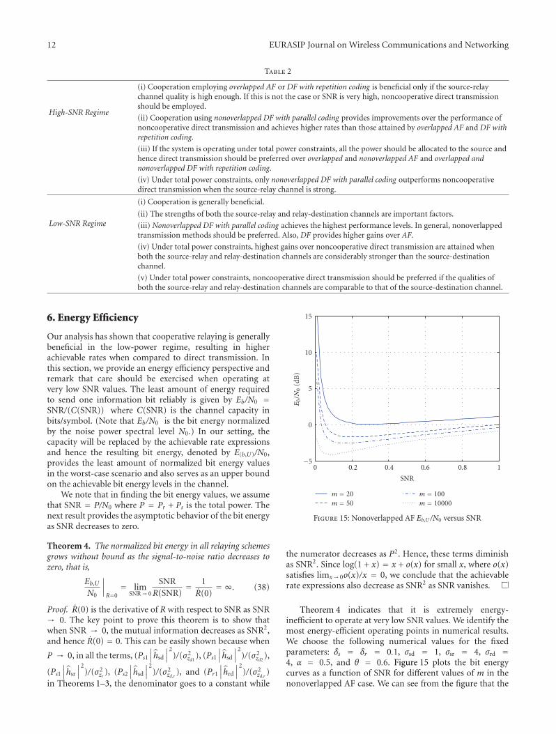
the numerator decreases as P2. Hence, these terms diminishas SNR2. Since log(1 + x) = x + o(x) for small x, where o(x)satisfies limx→ 0o(x)/x = 0, we conclude that the achievablerate expressions also decrease as SNR2 as SNR vanishes.
Theorem 4 indicates that it is extremely energy-inefficient to operate at very low SNR values. We identify themost energy-efficient operating points in numerical results.We choose the following numerical values for the fixedparameters: δs = δr = 0.1, σsd = 1, σsr = 4, σrd =4, α = 0.5, and θ = 0.6. Figure 15 plots the bit energycurves as a function of SNR for different values of m in thenonoverlapped AF case. We can see from the figure that the
EURASIP Journal on Wireless Communications and Networking 13
100908070605040
m
Overlapped AFNon-overlapped AFNon-overlapped DF P
Non-overlappd DF ROverlapped DF
−7
−6
−5
−4
−3
−2
−1
0
Min
imu
mEb/N
0(d
B)
Figure 16: Eb,U/N0 versus m for different transmission scheme
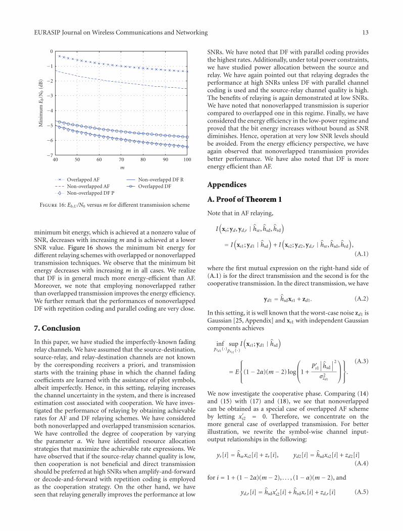
minimum bit energy, which is achieved at a nonzero value ofSNR, decreases with increasing m and is achieved at a lowerSNR value. Figure 16 shows the minimum bit energy fordifferent relaying schemes with overlapped or nonoverlappedtransmission techniques. We observe that the minimum bitenergy decreases with increasing m in all cases. We realizethat DF is in general much more energy-efficient than AF.Moreover, we note that employing nonoverlapped ratherthan overlapped transmission improves the energy efficiency.We further remark that the performances of nonoverlappedDF with repetition coding and parallel coding are very close.
7. Conclusion
In this paper, we have studied the imperfectly-known fadingrelay channels. We have assumed that the source-destination,source-relay, and relay-destination channels are not knownby the corresponding receivers a priori, and transmissionstarts with the training phase in which the channel fadingcoefficients are learned with the assistance of pilot symbols,albeit imperfectly. Hence, in this setting, relaying increasesthe channel uncertainty in the system, and there is increasedestimation cost associated with cooperation. We have inves-tigated the performance of relaying by obtaining achievablerates for AF and DF relaying schemes. We have consideredboth nonoverlapped and overlapped transmission scenarios.We have controlled the degree of cooperation by varyingthe parameter α. We have identified resource allocationstrategies that maximize the achievable rate expressions. Wehave observed that if the source-relay channel quality is low,then cooperation is not beneficial and direct transmissionshould be preferred at high SNRs when amplify-and-forwardor decode-and-forward with repetition coding is employedas the cooperation strategy. On the other hand, we haveseen that relaying generally improves the performance at low
SNRs. We have noted that DF with parallel coding providesthe highest rates. Additionally, under total power constraints,we have studied power allocation between the source andrelay. We have again pointed out that relaying degrades theperformance at high SNRs unless DF with parallel channelcoding is used and the source-relay channel quality is high.The benefits of relaying is again demonstrated at low SNRs.We have noted that nonoverlapped transmission is superiorcompared to overlapped one in this regime. Finally, we haveconsidered the energy efficiency in the low-power regime andproved that the bit energy increases without bound as SNRdiminishes. Hence, operation at very low SNR levels shouldbe avoided. From the energy efficiency perspective, we haveagain observed that nonoverlapped transmission providesbetter performance. We have also noted that DF is moreenergy efficient than AF.
Appendices
A. Proof of Theorem 1
Note that in AF relaying,
I(
xs; yd, yd,r | hsr, hsd, hrd
)
= I(
xs1; yd1 | hsd
)
+ I(
xs2; yd2, yd,r | hsr, hsd, hrd
)
,
(A.1)
where the first mutual expression on the right-hand side of(A.1) is for the direct transmission and the second is for thecooperative transmission. In the direct transmission, we have
yd1 = hsdxs1 + zd1. (A.2)
In this setting, it is well known that the worst-case noise zd1 isGaussian [25, Appendix] and xs1 with independent Gaussiancomponents achieves
infpzd1
(·)suppxs1 (·)
I(
xs1; yd1 | hsd
)
= E
⎧
⎪⎨
⎪⎩
(1− 2α)(m− 2) log
⎛
⎜⎝1 +
P′s1∣∣∣hsd
∣∣∣
2
σ2zd1
⎞
⎟⎠
⎫
⎪⎬
⎪⎭
.
(A.3)
We now investigate the cooperative phase. Comparing (14)and (15) with (17) and (18), we see that nonoverlappedcan be obtained as a special case of overlapped AF schemeby letting x′s2 = 0. Therefore, we concentrate on themore general case of overlapped transmission. For betterillustration, we rewrite the symbol-wise channel input-output relationships in the following:
yr[i] = hsrxs2[i] + zr[i], yd2[i] = hsdxs2[i] + zd2[i](A.4)
for i = 1 + (1− 2α)(m− 2), . . . , (1− α)(m− 2), and
yd,r[i] = hsdx′s2[i] + hrdxr[i] + zd,r[i] (A.5)
14 EURASIP Journal on Wireless Communications and Networking
for i = (1−α)(m−2)+1, . . . ,m−2. In AF, the signals receivedand transmitted by the relay have the following relation:
xr[i] = βyr[i− α(m− 2)],
where β �
√√√√√√
E{
|xr|2}
∣∣∣hsr
∣∣∣
2E{
|xs2|2}
+ E{
|zr|2} .
(A.6)
Now, we can write the channel in the vector form
⎛
⎝yd2[i]
yd,r[i + α(m− 2)]
⎞
⎠
︸ ︷︷ ︸
yd[i]
=⎛
⎝hsd 0
hrdβhsr hsd
⎞
⎠
︸ ︷︷ ︸
A
⎛
⎝xs[i]
xs[i + α(m− 2)]
⎞
⎠
︸ ︷︷ ︸
xs[i]
+
⎛
⎝
0 1 0
hrdβ 0 1
⎞
⎠
︸ ︷︷ ︸
B
⎛
⎜⎜⎝
zr[i]
zd2[i]
zd,r[i + α(m− 2)]
⎞
⎟⎟⎠
︸ ︷︷ ︸
z[i]
(A.7)
where i = 1 + (1 − 2α)(m − 2), ..., (1 − α)(m − 2) and β √
(E{|xr|2})/(∣∣∣hsr
∣∣∣
2E{|xs|2} + E{|zr|2}). Note that we have
defined xs = [xTs1, xTs2, x′Ts2 ]T , and the expression in (A.7) uses
the property that xs2( j) = xs( j+(1−2α)(m−2)) and x′s2( j) =xs( j + (1 − α)(m − 2)) for j = 1, . . . ,α(m − 2). The input-output mutual information in the cooperative phase can nowbe expressed as
I(
xs2, x′s2; yd2, yd,r | hsr, hsd, hrd
)
=(1−α)(m−2)
∑
i=1+(1−2α)(m−2)
I(
xs[i]; yd[i] | hsr, hsd, hrd
)
= α(m− 2)I(
xs; yd | hsrhsd, hrd
)
,
(A.8)
where in (A.8) we removed the dependence on i withoutloss of generality. Note that xs and yd are defined in (A.7).Now, we can calculate the worst-case capacity by proving thatGaussian distribution for zr , zd2, and zd,r provides the worstcase. We employ techniques similar to that in [25, Appendix].Any set of particular distributions for zr , zd2, and zd,r yieldsan upper bound on the worst case. Let us choose zr , zd2, andzd,r to be zero mean complex Gaussian distributed. Then asin [6, Appendix II],
infpzr (·),pzd2
(·),pzd,r(·)
suppxs2 (·),px′s2 (·)
I(
xs; yd | hsr, hsd, hrd
)
≤ E log det(
I +(
AE{
xsx†s}
A†)(
BE{
zz†}
B†)−1
)
,
(A.9)
where the expectation is with respect to the fading esti-mates. To obtain a lower bound, we compute the mutualinformation for the channel in (A.7) assuming that xs is
a zero-mean complex Gaussian with variance E{xsx†s }, butthe distributions of noise components zr , zd2, and zd,r arearbitrary. In this case, we have
I(
xs; yd; | hsr, hsd, hrd
)
= h(
xs | hsr, hsd, hrd
)
− h(
xs | yd, hsr, hsd, hrd
)
� logπeE{
xsx†s}
− logπe var(
xs | yd, hsr, hsd, hrd
)
,
(A.10)
where the inequality is due to the fact that Gaussiandistribution provides the largest entropy and hence [28,Chapter 9]
h(
xs | yd, hsr, hsd, hrd
)
≤ logπe var(
xs | yd, hsr, hsd, hrd
)
.
(A.11)
Above, h() denotes the differential entropy functional. From[25, Lemma 1, Appendix], we know that
var(
xs | yd, hsr, hsd, hrd
)
� E{(
xs − xs)(
xs − xs)† | hsr, hsd, hrd
} (A.12)
for ant estimate xs given yd, hsr, hsd, and hrd. If we substitutethe linear minimum mean-square-error (LMMSE) estimatexs = RXyR
−1y yd, where Rxy and Ry are cross-covariance and
covariance matrices respectively, into (A.10) and (A.12), weobtain
I(
xs; yd | hsr, hsd, hrd
)
≥ E log det(
I +(
E{
|xs|2}
AA†)(
BE{
zz†}
B†)−1
)
.
(A.13)
(Here, we use the property that det(I + AB) = det(I +BA).) Since the lower bound (A.13) applies for any noisedistribution, we can easily see that
infpzr (·),pzd2
(·),pzd,r(·)
suppxs2 (·),px′s2 (·)
I(
xs; yd | hsr, hsd, hrd
)
� E log det(
I +(
AE{
xsx†s}
A†)(
BE{
zz†}
B†)−1
)
.
(A.14)
From (A.9) and (A.14), we conclude that
infpzr (·),pzd2 (·),pzd,r (·)
suppxs2 (·),px′s2 (·)
I(
xs; yd | hsr, hsd, hrd
)
= Elogdet(
I +(
AE{
xsx†s}
A†)(
BE{
zz†}
B†)−1
)(A.15)
= E log
⎧
⎪⎨
⎪⎩
1 +Ps1
∣∣∣hsd
∣∣∣
2
σ2zd2
+ f
⎛
⎜⎝
Ps1∣∣∣hsr
∣∣∣
2
σ2zr
,Pr1
∣∣∣hrd
∣∣∣
2
σ2zd,r
⎞
⎟⎠
+q
⎛
⎜⎝
Ps1∣∣∣hsd
∣∣∣
2
σ2zd2
,Ps2
∣∣∣hsd
∣∣∣
2
σ2zd,r
,Ps1
∣∣∣hsr
∣∣∣
2
σ2zr
,Pr1
∣∣∣hrd
∣∣∣
2
σ2zd,r
⎞
⎟⎠
⎫
⎪⎬
⎪⎭
.
(A.16)
EURASIP Journal on Wireless Communications and Networking 15
In obtaining (A.16), we have used the fact that E{xsx†s } =(Ps1 0
0 Ps2
)
. Note also that in (A.16), Ps1,Ps2, and Pr1 are the
powers of source and relay symbols and are given in (29)–(31). Moreover, σ2
zd2, σ2
zr , and σ2zd,r
are the variances of thenoise components defined in (20). Now, combining (23),(A.1), (A.3), and (A.16), we obtain the achievable rateexpression in (24). Note that (25)–(28) are obtained by usingthe expressions for the channel estimates in (5)–(7) and noisevariances in (21) and (22).
B. Proof of Theorem 2
For DF with repetition coding in overlapped transmission,an achievable rate expression is
I(
xs1; yd1 | hsd
)
+ min{
I(
xs2; yr | hsr
)
, I(
xs2, x′s2; yd, yd,r | hsd, hrd
)}
.
(B.1)
Note that the first and second mutual information expres-sions in (B.1) are for the direct transmission between thesource and destination, and direct transmission betweenthe source and relay, respectively. Therefore, as in theproof of Theorem 1, the worst-case achievable rates can beimmediately seen to be equal to the first term on the right-hand side of (32) and I1, respectively.
In repetition coding, after successfully decoding thesource information, the relay transmits the same codewordas the source. As a result, the input-output relation in thecooperative phase can be expressed as
⎛
⎝yd2[i]
yd,r[i + α(m− 2)]
⎞
⎠
︸ ︷︷ ︸
yd[i]
=⎛
⎝hsd 0
hrdβ hsd
⎞
⎠
︸ ︷︷ ︸
A
⎛
⎝xs[i]
xs[i + α(m− 2)]
⎞
⎠
︸ ︷︷ ︸
xs[i]
+
⎛
⎝zd2[i]
zd,r[i + α(m− 2)]
⎞
⎠
︸ ︷︷ ︸
z[i]
,
(B.2)
where β ≤√
(E{|xr|2})/(E{|xs|2}). From (B.2), it is clear that
the knowledge of hsr is not required at the destination. Wecan easily see that (B.2) is a simpler expression than (A.7)in the AF case; therefore we can adopt the same methods asemployed in the proof of Theorem 1 to show that Gaussiannoise is the worst noise and I2 is the worst-case rate.
Acknowledgments
This work was supported in part by the NSF CAREER GrantCCF-0546384. The material in this paper was presented inpart at the 45th Annual Allerton Conference on Commu-nication, Control and Computing in September 2007 andin part at the 9th IEEE Workshop on Signal ProcessingAdvances for Wireless Communications (SPAWC) in July2008.
References
[1] E. C. van der Meulen, “Three-terminal communication chan-nels,” Advances in Applied Probability, vol. 3, no. 1, pp. 120–154, 1971.
[2] T. M. Cover and A. A. El Gamal, “Capacity theorems for therelay channel,” IEEE Transactions on Information Theory, vol.25, no. 5, pp. 572–584, 1979.
[3] A. A. El Gamal and M. Aref, “The capacity of the semide-terministic relay channel,” IEEE Transactions on InformationTheory, vol. 28, no. 3, p. 536, 1982.
[4] A. Sendonaris, E. Erkip, and B. Aazhang, “User cooperationdiversity—part I: system description,” IEEE Transactions onCommunications, vol. 51, no. 11, pp. 1927–1938, 2003.
[5] A. Sendonaris, E. Erkip, and B. Aazhang, “User cooperationdiversity—part II: implementation aspects and performanceanalysis,” IEEE Transactions on Communications, vol. 51, no.11, pp. 1939–1948, 2003.
[6] J. N. Laneman, D. N. C. Tse, and G. W. Wornell, “Cooperativediversity in wireless networks: efficient protocols and outagebehavior,” IEEE Transactions on Information Theory, vol. 50,no. 12, pp. 3062–3080, 2004.
[7] J. N. Laneman, “Cooperative diversity: models, algorithms,and architectures,” in Cooperation in Wireless Networks: Prin-ciples and Applications, chapter 1, Springer, Berlin, Germany,2006.
[8] R. U. Nabar, H. Bolcskei, and F. W. Kneubuhler, “Fading relaychannels: performance limits and space-time signal design,”IEEE Journal on Selected Areas in Communications, vol. 22, no.6, pp. 1099–1109, 2004.
[9] A. Host-Madsen and J. Zhang, “Capacity bounds and powerallocation for wireless relay channels,” IEEE Transactions onInformation Theory, vol. 51, no. 6, pp. 2020–2040, 2005.
[10] D. Gunduz and E. Erkip, “Opportunistic cooperation bydynamic resource allocation,” IEEE Transactions on WirelessCommunications, vol. 6, no. 4, pp. 1446–1454, 2007.
[11] Y. Yao, X. Cai, and G. B. Giannakis, “On energy efficiencyand optimum resource allocation of relay transmissionsin the low-power regime,” IEEE Transactions on WirelessCommunications, vol. 4, no. 6, pp. 2917–2927, 2005.
[12] Y. Liang, V. V. Veeravalli, and H. V. Poor, “Resource allocationfor wireless fading relay channels: max-min solution,” IEEETransactions on Information Theory, vol. 53, no. 10, pp. 3432–3453, 2007.
[13] Y. Liang and V. V. Veeravalli, “Gaussian orthogonal relaychannels: optimal resource allocation and capacity,” IEEETransactions on Information Theory, vol. 51, no. 9, pp. 3284–3289, 2005.
[14] C. T. K. Ng and A. Goldsmith, “The impact of CSI andpower allocation on relay channel capacity and cooperationstrategies,” IEEE Transactions onWireless Communications, vol.7, no. 12, pp. 5380–5389, 2008.
[15] A. Host-Madsen, “Capacity bounds for cooperative diversity,”IEEE Transactions on Information Theory, vol. 52, no. 4, pp.1522–1544, 2006.
[16] G. Kramer, M. Gastpar, and P. Gupta, “Cooperative strategiesand capacity theorems for relay networks,” IEEE Transactionson Information Theory, vol. 51, no. 9, pp. 3037–3063, 2005.
[17] P. Mitran, H. Ochiai, and V. Tarokh, “Space-time diversityenhancements using collaborative communications,” IEEETransactions on Information Theory, vol. 51, no. 6, pp. 2041–2057, 2005.
16 EURASIP Journal on Wireless Communications and Networking
[18] G. Kramer, I. Maric, and R. D. Yates, “Cooperative communi-cations,” Foundations and Trends in Networking, vol. 1, no. 3-4,pp. 271–425, 2006.
[19] G. Kramer, R. Berry, A. A. El Gamal, et al., “Introduction tothe special issue on models, theory, and codes for relaying andcooperation in communication networks,” IEEE Transactionson Information Theory, vol. 53, no. 10, pp. 3297–3301, 2007.
[20] B. Wang, J. Zhang, and L. Zheng, “Achievable rates and scalinglaws of power-constrained wireless sensory relay networks,”IEEE Transactions on Information Theory, vol. 52, no. 9, pp.4084–4104, 2006.
[21] F. Gao, T. Cui, and A. Nallanathan, “On channel estimationand optimal training design for amplify and forward relaynetworks,” IEEE Transactions onWireless Communications, vol.7, no. 5, part 2, pp. 1907–1916, 2008.
[22] C. S. Patel and G. L. Stuber, “Channel estimation for amplifyand forward relay based cooperation diversity systems,” IEEETransactions on Wireless Communications, vol. 6, no. 6, pp.2348–2356, 2007.
[23] A. S. Avestimehr and D. N. C. Tse, “Outage capacity ofthe fading relay channel in the low-SNR regime,” IEEETransactions on Information Theory, vol. 53, no. 4, pp. 1401–1415, 2007.
[24] M. C. Gursoy, “An energy efficiency perspective on trainingfor fading channels,” in Proceedings of IEEE InternationalSymposium on Information Theory (ISIT ’07), pp. 1206–1210,Nice, France, June 2007.
[25] B. Hassibi and B. M. Hochwald, “How much training isneeded in multiple-antenna wireless links?” IEEE Transactionson Information Theory, vol. 49, no. 4, pp. 951–963, 2003.
[26] L. Tong, B. M. Sadler, and M. Dong, “Pilot-assisted wirelesstransmissions,” IEEE Signal Processing Magazine, vol. 21, no.6, pp. 12–25, 2004.
[27] S. Verdu, “Spectral efficiency in the wideband regime,” IEEETransactions on Information Theory, vol. 48, no. 6, pp. 1319–1343, 2002.
[28] T. M. Cover and J. A. Thomas, Elements of Information Theory,John Wiley & Sons, New York, NY, USA, 1991.